EP3976338B1 - Vorrichtung zum führen eines folienschlauchs - Google Patents
Vorrichtung zum führen eines folienschlauchs Download PDFInfo
- Publication number
- EP3976338B1 EP3976338B1 EP19729229.5A EP19729229A EP3976338B1 EP 3976338 B1 EP3976338 B1 EP 3976338B1 EP 19729229 A EP19729229 A EP 19729229A EP 3976338 B1 EP3976338 B1 EP 3976338B1
- Authority
- EP
- European Patent Office
- Prior art keywords
- coupling rod
- frame
- coupling
- film
- guide
- Prior art date
- Legal status (The legal status is an assumption and is not a legal conclusion. Google has not performed a legal analysis and makes no representation as to the accuracy of the status listed.)
- Active
Links
Images




Classifications
-
- B—PERFORMING OPERATIONS; TRANSPORTING
- B29—WORKING OF PLASTICS; WORKING OF SUBSTANCES IN A PLASTIC STATE IN GENERAL
- B29C—SHAPING OR JOINING OF PLASTICS; SHAPING OF MATERIAL IN A PLASTIC STATE, NOT OTHERWISE PROVIDED FOR; AFTER-TREATMENT OF THE SHAPED PRODUCTS, e.g. REPAIRING
- B29C48/00—Extrusion moulding, i.e. expressing the moulding material through a die or nozzle which imparts the desired form; Apparatus therefor
- B29C48/25—Component parts, details or accessories; Auxiliary operations
- B29C48/355—Conveyors for extruded articles
-
- B—PERFORMING OPERATIONS; TRANSPORTING
- B29—WORKING OF PLASTICS; WORKING OF SUBSTANCES IN A PLASTIC STATE IN GENERAL
- B29C—SHAPING OR JOINING OF PLASTICS; SHAPING OF MATERIAL IN A PLASTIC STATE, NOT OTHERWISE PROVIDED FOR; AFTER-TREATMENT OF THE SHAPED PRODUCTS, e.g. REPAIRING
- B29C48/00—Extrusion moulding, i.e. expressing the moulding material through a die or nozzle which imparts the desired form; Apparatus therefor
- B29C48/03—Extrusion moulding, i.e. expressing the moulding material through a die or nozzle which imparts the desired form; Apparatus therefor characterised by the shape of the extruded material at extrusion
- B29C48/07—Flat, e.g. panels
- B29C48/08—Flat, e.g. panels flexible, e.g. films
-
- B—PERFORMING OPERATIONS; TRANSPORTING
- B29—WORKING OF PLASTICS; WORKING OF SUBSTANCES IN A PLASTIC STATE IN GENERAL
- B29C—SHAPING OR JOINING OF PLASTICS; SHAPING OF MATERIAL IN A PLASTIC STATE, NOT OTHERWISE PROVIDED FOR; AFTER-TREATMENT OF THE SHAPED PRODUCTS, e.g. REPAIRING
- B29C48/00—Extrusion moulding, i.e. expressing the moulding material through a die or nozzle which imparts the desired form; Apparatus therefor
- B29C48/03—Extrusion moulding, i.e. expressing the moulding material through a die or nozzle which imparts the desired form; Apparatus therefor characterised by the shape of the extruded material at extrusion
- B29C48/09—Articles with cross-sections having partially or fully enclosed cavities, e.g. pipes or channels
- B29C48/10—Articles with cross-sections having partially or fully enclosed cavities, e.g. pipes or channels flexible, e.g. blown foils
-
- B—PERFORMING OPERATIONS; TRANSPORTING
- B29—WORKING OF PLASTICS; WORKING OF SUBSTANCES IN A PLASTIC STATE IN GENERAL
- B29C—SHAPING OR JOINING OF PLASTICS; SHAPING OF MATERIAL IN A PLASTIC STATE, NOT OTHERWISE PROVIDED FOR; AFTER-TREATMENT OF THE SHAPED PRODUCTS, e.g. REPAIRING
- B29C48/00—Extrusion moulding, i.e. expressing the moulding material through a die or nozzle which imparts the desired form; Apparatus therefor
- B29C48/25—Component parts, details or accessories; Auxiliary operations
- B29C48/88—Thermal treatment of the stream of extruded material, e.g. cooling
- B29C48/885—External treatment, e.g. by using air rings for cooling tubular films
-
- B—PERFORMING OPERATIONS; TRANSPORTING
- B29—WORKING OF PLASTICS; WORKING OF SUBSTANCES IN A PLASTIC STATE IN GENERAL
- B29C—SHAPING OR JOINING OF PLASTICS; SHAPING OF MATERIAL IN A PLASTIC STATE, NOT OTHERWISE PROVIDED FOR; AFTER-TREATMENT OF THE SHAPED PRODUCTS, e.g. REPAIRING
- B29C48/00—Extrusion moulding, i.e. expressing the moulding material through a die or nozzle which imparts the desired form; Apparatus therefor
- B29C48/25—Component parts, details or accessories; Auxiliary operations
- B29C48/88—Thermal treatment of the stream of extruded material, e.g. cooling
- B29C48/90—Thermal treatment of the stream of extruded material, e.g. cooling with calibration or sizing, i.e. combined with fixing or setting of the final dimensions of the extruded article
- B29C48/901—Thermal treatment of the stream of extruded material, e.g. cooling with calibration or sizing, i.e. combined with fixing or setting of the final dimensions of the extruded article of hollow bodies
- B29C48/903—Thermal treatment of the stream of extruded material, e.g. cooling with calibration or sizing, i.e. combined with fixing or setting of the final dimensions of the extruded article of hollow bodies externally
-
- B—PERFORMING OPERATIONS; TRANSPORTING
- B29—WORKING OF PLASTICS; WORKING OF SUBSTANCES IN A PLASTIC STATE IN GENERAL
- B29C—SHAPING OR JOINING OF PLASTICS; SHAPING OF MATERIAL IN A PLASTIC STATE, NOT OTHERWISE PROVIDED FOR; AFTER-TREATMENT OF THE SHAPED PRODUCTS, e.g. REPAIRING
- B29C48/00—Extrusion moulding, i.e. expressing the moulding material through a die or nozzle which imparts the desired form; Apparatus therefor
- B29C48/25—Component parts, details or accessories; Auxiliary operations
- B29C48/88—Thermal treatment of the stream of extruded material, e.g. cooling
- B29C48/90—Thermal treatment of the stream of extruded material, e.g. cooling with calibration or sizing, i.e. combined with fixing or setting of the final dimensions of the extruded article
- B29C48/907—Thermal treatment of the stream of extruded material, e.g. cooling with calibration or sizing, i.e. combined with fixing or setting of the final dimensions of the extruded article using adjustable calibrators, e.g. the dimensions of the calibrator being changeable
-
- B—PERFORMING OPERATIONS; TRANSPORTING
- B29—WORKING OF PLASTICS; WORKING OF SUBSTANCES IN A PLASTIC STATE IN GENERAL
- B29C—SHAPING OR JOINING OF PLASTICS; SHAPING OF MATERIAL IN A PLASTIC STATE, NOT OTHERWISE PROVIDED FOR; AFTER-TREATMENT OF THE SHAPED PRODUCTS, e.g. REPAIRING
- B29C55/00—Shaping by stretching, e.g. drawing through a die; Apparatus therefor
- B29C55/28—Shaping by stretching, e.g. drawing through a die; Apparatus therefor of blown tubular films, e.g. by inflation
-
- B—PERFORMING OPERATIONS; TRANSPORTING
- B29—WORKING OF PLASTICS; WORKING OF SUBSTANCES IN A PLASTIC STATE IN GENERAL
- B29C—SHAPING OR JOINING OF PLASTICS; SHAPING OF MATERIAL IN A PLASTIC STATE, NOT OTHERWISE PROVIDED FOR; AFTER-TREATMENT OF THE SHAPED PRODUCTS, e.g. REPAIRING
- B29C48/00—Extrusion moulding, i.e. expressing the moulding material through a die or nozzle which imparts the desired form; Apparatus therefor
- B29C48/001—Combinations of extrusion moulding with other shaping operations
- B29C48/0018—Combinations of extrusion moulding with other shaping operations combined with shaping by orienting, stretching or shrinking, e.g. film blowing
Definitions
- the invention relates to a device for guiding a film tube emerging from a film blowing head and drawn off in a production direction, with a frame through which the film tube can be guided in the production direction, and several adjustment units distributed over the circumference for adjusting film guide elements transversely to the production direction.
- the adjustment units each have a pivot arm which is pivotally attached to the frame, a carrier for at least one of the film guide elements which is pivotally connected to the pivot arm, and a coupling rod which is pivotally connected to the carrier.
- plastic melt is extruded from an extrusion tool with a ring channel nozzle and drawn out.
- the plasticized, plastically formable and expandable hot film tube is blown on the outer and often also the inner circumference with cooling air from a cooling ring or an internal cooling device and cooled.
- the tubular film bubble is guided lengthwise over a device for guiding the film tube (often also referred to as a guide device, calibration device or calibration basket) and a flattening device and is squeezed and drawn off as a flat tube from conveyor rollers in a withdrawal unit.
- a device for guiding the film tube often also referred to as a guide device, calibration device or calibration basket
- a flattening device is squeezed and drawn off as a flat tube from conveyor rollers in a withdrawal unit.
- freezing of the film tube i.e.
- the calibration device has film guide elements distributed over the circumference, which serve to guide the film tube.
- the film guide elements can, for example, have rollers that lie tangentially on the film tube and guide it.
- the film guide elements are Radially adjustable transversely to the production direction of the film tube and thus adaptable to different diameters of the film tube.
- the guide device described therein has a support structure to which several movable arms are pivotally attached.
- the arms carry guide means that are held in contact with the film tube.
- the movable arms consist of an articulated square and each comprise a square body that is pivotally attached to the support structure like a flap, an articulated rod that is rotatably attached to the support structure at one end, and a support element for the guide means that is rotatably attached to the other end of the articulated rod.
- the movable arms are arranged in such a way that the guide means are always held tangentially to the film tube.
- the movable arms, the articulated rods and the support elements are each attached to the support structure and to one another in such a way that they form a trapezoidal arrangement in the manner of a four-link rotary joint mechanism.
- connecting elements that connect the articulated rod to the support element describe a circular arc around the end of the articulated rod that is rotatably attached to the support structure.
- This arrangement holds guide elements in the form of horizontally arranged rotating rollers tangentially to the film tube.
- the positioning of the rollers is only approximately centric to the film bubble.
- contact and non-contact calibration and guide devices are known from the state of the art, the film guide elements of which are adjusted to the respective diameter of the film tube using various adjustment units.
- the film guide elements are divided into calibration segments around the circumference according to the state of the art.
- swivel arm mechanisms with tangential swiveling of the film guide elements and lever or scissor mechanisms with radially centric adjustment of the film guide elements are known for diameter adjustment.
- Scissor mechanisms such as EP 1 714 770 B1 or EP 1 491 319 B1 , allow a radially centric adjustment of the calibration segments.
- the indirect linear adjustment movement is subject to a permanent change in the adjustment speed at a constant drive speed, which leads to an increased control effort, especially in modern systems with automatic control of the diameter adjustment.
- a calibration device with contactless film guide elements shows EP 2 801 467 B1
- the Venturi or Bernoulli effect is used here, whereby an air flow guided at sufficient speed tangentially along a surface of the guide element facing the tubular film exerts a suction and fixing force on a sufficiently close moving element, in this case the tubular film, without any contact occurring. Due to this force, in conjunction with the air cushion as a counterforce, the tubular film assumes a stable distance position from the film guide element.
- the film guide elements with contactless air cushion guidance can be individual elements arranged parallel to one another in the direction of production, or crossed pairs of elements in a V position that are offset in height and arranged parallel to one another in the direction of production.
- All known designs feature mechanical synchronization of the calibration segments arranged around the circumference.
- the designs according to WO 2007/079899 A1 and WO 2016/139573 A1 have in common a direct coupling of the additionally pivotable film guide elements of the respective calibration segments.
- the coupling elements used are telescopic or foldable in one plane and rigid in another plane and ensure a common tangential and centric alignment of the film guide elements to the film tube via the adjustment path.
- the coupling elements have no connection to the outer rigid frame. This design is therefore difficult to control for larger designs and tends to lead to inaccuracy in the positioning of the film guide elements to the film tube and to jamming.
- the object of the present invention is to provide a device for guiding a film tube emerging from a film blowing head and drawn off in a production direction, in which film guide elements are positioned on the film tube as precisely as possible when the diameter of the film tube changes.
- the object is achieved by a device for guiding a film tube emerging from a film blowing head and drawn off in a production direction, with the features of claim 1.
- the diameter-adjustable device for guiding the film tube (calibration and guide device) according to the invention enables a precise, central positioning of the film guide elements on the film tube for each diameter of the film tube with little structural effort. This is particularly achieved by the adjustment mechanism, which is arranged between the coupling rod and the frame and connects the coupling rod to the frame in an articulated manner.
- the adjustment mechanism By arranging the adjustment mechanism between the coupling rod and the frame, the adjustment of the film guide elements relative to the film tube can be specified more precisely than is possible with the state of the art with only a trapezoidal arrangement of the adjustment unit.
- the coupling rod executes translational movements at the end connected to the carrier and at the end connected to the actuating mechanism, which are not congruent or have non-congruent movement vectors.
- the coupling rods can be simple rods with a round, square or rectangular cross-section. They can also be designed in a more complex way to For example, milled parts, turned parts, stamped parts, metal castings, metal pressed parts, injection molded parts, lasered sheet metal parts or sheet metal edge parts.
- the at least one first adjustment unit forms an unevenly geared transmission gear, namely a coupling gear or a cam gear. These two types of gear offer the most options in terms of structures and properties to ensure precise alignment of the film guide elements with respect to the film tube.
- the at least one first adjustment unit can form a six-link coupling gear.
- the complexity of the gear structure is relatively low, allowing for high precision of the movement sequences and adaptability to different conditions.
- the coupling gear can in particular be designed as a Stephenson chain.
- the adjusting mechanism can be coupled to three elements, namely to the pivot arm of the at least one first adjusting unit, to the coupling rod of the at least one first adjusting unit and to the frame.
- the adjustment mechanism can have a coupling element which is connected in an articulated manner on the one hand to the coupling rod of the at least one first adjustment unit and on the other hand to the frame.
- articulated means that the coupling element is connected to the coupling rod and the frame by means of a rotary joint for a pivotable connection, by means of a sliding joint for a displaceable connection or a combination of both.
- the coupling element is pivotally connected to the coupling rod of the at least one first adjustment unit.
- the adjusting mechanism can also have a connecting lever which is pivotally connected on the one hand to the pivot arm of the at least one first adjusting unit and on the other hand to the coupling element of the at least one first adjusting unit.
- the connecting lever can be pivotally connected to the coupling rod instead of to the coupling element.
- the swivel arm comprises all rigidly connected components that are moved or swiveled uniformly, in particular a swivel plate arranged outside a swivel axis about which the swivel arm is pivotably attached to the frame, for connection to a drive.
- the coupling element can be displaceably connected to the coupling rod of the at least one first adjustment unit on the one hand and pivotably connected to the frame on the other hand.
- the adjusting mechanism can comprise a curve guide mechanism with a guide and a driver, wherein the coupling rod is coupled to the frame or the swivel arm via the curve guide mechanism and wherein the driver is guided along the guide in a translationally movable manner.
- the driver can be arranged on one element of the group consisting of the coupling rod and the frame and the guide on the other element of the group consisting of the coupling rod and the frame.
- the driver can be arranged on one element of the group consisting of the coupling rod and the swivel arm and the guide on the other element of the group consisting of the coupling rod and the swivel arm.
- the driver can be connected to the coupling rod and the guide can be arranged on the frame.
- the driver can be firmly connected to the coupling rod or can be designed as a sliding element that is pivotably or rotatably connected to the coupling rod.
- the driver can a simple bolt, a fitting screw or even a rolling element such as a ball bearing or a rotatably mounted sleeve.
- the driver can also be incorporated into the coupling rod in a more complex design.
- the guide can be a curved track, for example as a cam disk or curved groove.
- the guide for example in the form of a cam disc, can be attached directly or indirectly to the rigid frame.
- the cam disc can also be part of the rigid frame, i.e. the track is incorporated directly into the rigid frame.
- the swivel arm also includes a swivel plate located outside the swivel axis to drive the swivel arm. It is conceivable that the track is incorporated directly into the swivel plate and the swivel plate serves as a cam disk.
- the coupling element can be part of a sliding joint that is directly or indirectly attached to the rigid frame so that it can rotate.
- a front end of the coupling rod is directly or indirectly connected to the pivoting supports for the film guide elements and a rear end of the coupling rod is slidably guided on the sliding joint.
- the coupling rod can have a driver that engages in the track of the associated guide or cam disk and is positively guided therein.
- the angle between the swivel arms and the associated coupling rods changes. This causes the driver to move within the track of the cam disc, or, if the arrangement is reversed, the track of the cam disc moves along the driver, so that the exact axial displacement of the coupling rod required for the diameter being approached is generated for an exactly central alignment of the film guide elements to the film tube.
- the distance from the front end of the coupling rod to the rotating sliding joint changes over the adjustment path.
- the front end is the end of the coupling rod connected to the carrier.
- the shape of the track is designed in such a way that the exact right swivel angle for the supports of the film guide elements is set for any diameter of the calibration and guide device.
- the device can further comprise a synchronization mechanism via which the adjustment units are coupled to one another in order to synchronize the adjustment movements.
- the synchronization mechanism can comprise push rods via which the adjustment units are coupled to one another around the circumference of the device.
- At least one second adjustment unit of the plurality of adjustment units has a coupling element which is articulated on the one hand to the coupling rod of the at least one second adjustment unit and on the other hand to the frame. and is otherwise free from a direct coupling with the respective actuating arm.
- the synchronization mechanism can have push rods via which the coupling elements are coupled to one another around the circumference of the device.
- the swivel arms hinged to the rigid frame are coupled to one another in a rotating manner for a synchronous swiveling process.
- the coupled swivel arms are moved by a common drive, which has a linear or rotary actuator.
- the rotating coupling is preferably formed by a simple and robust push rod system.
- other rotating couplings such as a chain or toothed belt drive are also conceivable.
- the rotating coupling system of the swivel arms, together with the drive or the actuator forms a first movable actuating system and implements the diameter adjustment of the calibration and guide device.
- a second movable actuating system is used to swivel the supports for the film guide elements depending on the diameter.
- the supports are attached to the free end of the swivel arms and are mounted so that they can rotate about a swivel axis parallel to the production direction.
- the first and second movable actuating systems are coupled by means of the actuating mechanism on only one of the swivel arms, and the coupling rods are also coupled to one another in a synchronous, rotating manner, for example by means of push rods.
- the coupling rods are also coupled to one another in a synchronous, rotating manner, for example by means of push rods.
- other combinations are also conceivable, for example coupling by means of an actuating mechanism on every second or third of the swivel arms with a synchronous mechanical coupling of the coupling rods in between.
- the drive concept is also reversible in that the linear or rotary actuator is part of the second movable actuating system.
- the actuating speed of the actuator is constant, the resulting adjustment speed of the diameter is not constant. If a constant adjustment speed is desired, for example in systems with automated diameter adjustment of the calibration and guide device in control loops, the actuator adjustment speed must be adjusted over the diameter. can be varied.
- the film guide elements can comprise individual elements arranged parallel and spaced apart in the direction of production, as well as crossed pairs of elements in a V-position that are offset in height and arranged parallel and spaced apart in the direction of production.
- the film guide elements attached to the supports can, for example, be mounted rollers with different heat-insulating or anti-adhesive casings or coatings. It can also be provided that the entire roller casing is made of a heat-insulating material, for example carbon fiber.
- the film guide elements can also be rigid rods with a sliding coating (straight or slightly curved towards the film tube).
- the film guide elements can also be rigid round rods on which several short ring-shaped bodies made of a heat-insulating material are lined up in a rotating manner.
- the film guide elements can be rigid bars (straight or slightly curved towards the film bubble) that form an air cushion that guides the film tube without contact and without direct component contact.
- the carriers each have two, for example elongated, film guide elements, for example in the form of rollers or air beams, which are spaced apart from one another in the direction of production and arranged in a V-shape overlap.
- film guide elements for example in the form of rollers or air beams, which are spaced apart from one another in the direction of production and arranged in a V-shape overlap.
- rollers or similar contacting film guide elements as described above, these are held in contact with the film tube.
- air beams these are held so close to the film tube that they can hold the film tube using the Venturi or Bernoulli effect. Since the two film guide elements arranged in a V-shape relative to one another are moved simultaneously by one of the adjustment units, a particularly precise centric alignment of the film guide elements relative to the film tube is required so that both film guide elements are held evenly in contact with the film tube or close to it.
- the swivel arms can be in a
- the exemplary design can be designed as cut-to-size shaped sheets with stabilizing edges. Depending on the load, a cross-sectional height is selected that decreases towards the front towards the support of the film guide elements.
- cooling gas extraction elements can be installed between, below or above film guide elements, which are arranged on the adjustment units.
- These cooling gas extraction elements are preferably tubular with a round or square cross-section or designed as a sheet metal housing construction and preferably have one or more openings on their inner contour and/or underside for extracting cooling gas which flows from the cooling process in the direction of production along the film tube and is loaded with oily or waxy monomers which outgas from the hot melt.
- the inner contour of the cooling gas extraction elements can be straight or slightly curved towards the tubular film, with the radius of curvature roughly corresponding to the largest radius of the tubular film. This curvature can also be approximated by several straight sections and corresponding bend angles.
- the cooling gas extraction elements are preferably attached to the pivoting support like the film guide elements and are moved together with the film guide elements relative to the tubular film bubble when the diameter of the calibration and guide device is adjusted. This ensures that the cooling gas extraction elements function effectively for all diameters.
- the extracted cooling gas is removed via hoses and pipes via a central extraction fan. Partial or complete extraction of the contaminated cooling gas above the freezing point in the area of the calibration and guide device prevents or reduces contamination of the subsequent system components due to deposits of monomers.
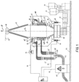
- FIG. 1 a film blowing system for producing the film tube is shown in side view and partly in longitudinal section through a longitudinal axis of a blown film tube.
- Thermoplastic material fed in granulate form via the hoppers 13, 14 is plasticized and homogenized by pressure and additional heating medium in a screw of the extruder 12 and pressed into a blow head 15 with a vertical axis connected to the extruder.
- the blow head 15 has an annular nozzle on its upper side (not shown in detail), from which an expanding, axisymmetric film tube 16 made of initially still plasticized film material emerges.
- the film tube 16' After the film material has solidified, the film tube 16' essentially retains its diameter.
- the film tube 16' is pressed flat in a flattening device 17 and pulled upwards via a pull-off device 18.
- the flattened film tube 16" is then wound onto coils.
- the functional terms "before” and “downstream of” are used in such a way that they mean “below” and "above” in spatial terms.
- a cooling gas ring 19 with several gas supply lines 20 is shown directly above the blowing head 15.
- the cooling gas ring 19 has internal outlet nozzles 21 from which the cooling gas flows out and flows in a ring shape essentially parallel to the wall of the film tube 16, which is under increased internal pressure.
- the cooling gas flow is symbolized by arrows 22.
- the film tube 16 plasticized in this area initially expands in diameter under the aforementioned excess pressure inside until it hardens under the effect of the cooling gas and assumes a constant diameter.
- the point of transition from the plasticized material to the hardened material is called the "freezing point" and is designated by 23.
- the film guide elements 47 with superimposed Contains roller arrangements which are essentially arranged in a ring around the film tube 16'.
- the roller arrangements are generally located on pivoting segments which form individual partial circumferences and by means of which the diameter of the calibration device can be changed. In cross-section, these segments can form a simplified polygonal calibration device.
- the still relatively warm film tube 16' is stabilized in cross-section by the calibration and guide device 24 and centered with respect to the inlet into the flattening device 17.
- the calibration and guide device 24 can be arranged so that it can be adjusted in height relative to the blow head 15 in order to always be able to assume an optimal height position relative to the freezing limit.
- Extraction lines 27 are connected to the gas extraction ring 25 at a distance around the circumference.
- the cooling gas contaminated with outgassing is symbolized by arrows 28.
- an adjustable aperture 29 which seals the film tube 16'.
- the aperture 29 can be adjusted in its opening cross-section via an adjustment device 30 and can therefore be adapted to different diameters of the film tube 16'. Sealing the film tube above the gas extraction ring 25 prevents clean air from being sucked in from an area downstream of the gas extraction ring, so that the extraction of the contaminated cooling gas is optimized with low energy consumption.
- the calibration and guide device 24 there is a further gas extraction ring or a plurality of individual gas extraction funnels or, as shown, gas extraction bars 31, which are connected to a plurality of extraction lines 33 distributed over the circumference.
- at least one gas extraction bar or several gas extraction bars arranged one above the other can be assigned to one of the previously mentioned segments of the calibration device, so that an adaptation of the calibration device to different diameters of the film tube 16' simultaneously allows an adaptation of the additional extraction device to the different diameters.
- the majority of the extraction lines 27 are first merged into a line 27'.
- the majority of the extraction lines 33 are merged into a single line 33'.
- the lines 27' and 33' are then combined into a single gas extraction line 43, with a control flap 34 arranged in the area of a pipe 35.
- a suction fan 44 is connected to the extraction line 43.
- a filter for example an electrostatic filter 45, can be integrated in the extraction line 43 before or after the suction fan 44 if it is impossible for environmental reasons to blow the extraction gases off into the environment outside a production hall.
- a condensate separator can also be provided which separates the harmful outgassing contained in the film tube by means of flow mechanics and/or by cooling the extraction gases.
- a control unit 36 with a processor controls the extraction fan 44 via a control line 37 and another control unit 39 for controlling the adjustment device 30 for the aperture 29 via a control line 38.
- the signals from a cooling gas flow sensor 41 in the cooling air supply lines 20 are transmitted to the control unit 36 via a measuring line 40.
- Signals about the pressure and flow conditions at the electrostatic filter 45 are transmitted to the control unit 36 via a measuring line 42.
- the control unit 36 can also regulate the cooling gas fan (also not shown) using a processor via another control line (not shown here).
- the entire area from the first cooling gas ring 19 to the gas extraction ring 25 is enclosed by a housing 46 so that the cooling gas contaminated with outgassing is kept away from the operating personnel's workplace.
- the lines 27, 33 are sealed and run through the housing.
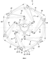
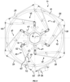
- FIG 2 shows a plan view of a first embodiment of a device for guiding a film tube 16 emerging from a film blowing head and drawn off in a production direction (calibration and guiding device 24).
- the calibration and guiding device 24 has a frame 48 to which the movable elements described below are attached and which is optionally arranged so as to be height-adjustable relative to the blowing head.
- the frame 48 forms a central Passage through which the film tube 16 is guided parallel to the longitudinal axis L or in the direction of production P according to Figure 1 .
- 6 adjustment units 49 are distributed around the circumference. The adjustment units 49 serve to adjust film guide elements 47 in a direction radial to the longitudinal axis L.
- the adjustment units 49 each have a pivot arm 50 which is pivotably attached to the frame 48.
- the pivot arm 50 can pivot about a pivot axis which is arranged parallel to the longitudinal axis L.
- the adjustment units 49 each have a carrier 51, which in the embodiment shown carries two film guide elements 47 in the form of rollers, which are spaced apart from one another in the production direction and arranged in a V-shape overlap.
- the carrier 51 is pivotally connected to the pivot arm 50.
- the carrier 51 is pivotally connected to the pivot arm 50 about a pivot axis, which is arranged parallel to the longitudinal axis L.
- the adjustment units 49 each have a coupling rod 52 which is pivotally connected to the carrier 51.
- the adjustment units 49 each have an adjustment mechanism by means of which the coupling rod 52 is connected in an articulated manner to the frame 48.
- the adjusting mechanism comprises a coupling element 53 and a connecting lever 54.
- the coupling element 53 is connected in an articulated manner to the frame 48, to the coupling rod 52 and to the connecting lever 54.
- the coupling element 53 is pivotally connected to the frame 48, the coupling rod 52 and the connecting lever 54.
- the connecting lever 54 is also pivotally connected to the pivot arm 50.
- the pivot arm 50 is firmly connected to a pivot plate 55, which is arranged on a side of the pivot axis facing away from the carrier 51, about which the pivot arm 50 is pivotally attached to the frame 48.
- the connecting lever 54 is directly connected to the pivot plate 55. pivotally connected.
- the connecting lever 54 is thus pivotally connected to the pivot arm 50 via the pivot plate 55.
- a drive 56 is also attached to the frame 48.
- the drive 56 is designed in the form of a solenoid, with which an actuator 57 in the form of a piston rod can be driven linearly.
- the actuator 57 is pivotally connected to the pivot plate 55 of one of the adjustment units 49.
- a housing of the drive 56 is pivotally connected to the frame 48.
- the drive 56 is thus supported against the frame 48, whereby the pivot arm 50 can be pivoted by adjusting the actuator 57. If the actuator 57 is moved by the Figure 2 shown inserted position into the Figure 3 shown extended position, the swivel arm 50, which is connected to the drive 56, is swiveled inwards so that the film guide elements 47 enclose a smaller diameter and can thus guide a film tube 16 with a smaller diameter.
- the calibration and guide device 24 has a synchronization mechanism to synchronize the movement of all adjustment units 49.
- the synchronization mechanism has push rods 58, which each couple the swivel plate 55 to one another over the circumference of adjacent adjustment units 49.
- the push rods 58 are each pivotally connected to the two swivel plates 55 of adjacent adjustment units 49. The pivoting movement of the adjustment unit 49 that is connected to the drive 56 via the swivel plate 55 is thus transmitted to the other adjustment units 49 that are not directly connected to the drive 56, so that all adjustment units 49 are moved synchronously.
- Figure 4 shows a second embodiment of a calibration and guiding device 24, wherein components that correspond to components of the first embodiment are provided with the same reference numerals and are described there.
- the calibration and guiding device 24 according to the second embodiment has a first adjustment unit 59 and five second adjustment units 60.
- the first adjustment unit 59 is identical in terms of its function and kinematics to the adjustment units of the calibration and guiding device according to the first embodiment.
- the coupling element 53 has a lever arm 61 which relative to a pivot axis between the coupling element 53 and the connecting lever 54 on a side facing away from the coupling rod 52.
- the lever arm 61 is an integral part of the coupling element 53.
- the coupling elements 53 of the second adjustment units 60 are designed in a similar way to the coupling element 53 of the first adjustment unit 59. In contrast to the first adjustment unit 59, the second adjustment units 60 do not have a connecting lever 54.
- a first synchronization mechanism is provided which is identical to the synchronization mechanism of the first embodiment of the calibration and guide device.
- a second synchronization mechanism is provided which has push rods 62 by means of which the coupling elements 53 of two adjustment units 59, 60 adjacent to one another over the circumference are coupled to one another. All adjustment units 59, 60 are coupled to one another in pairs over the circumference, so that the swivel movement of the coupling element 53 of the first adjustment unit 59 is transmitted synchronously to all second adjustment units 60.
- Figure 5 shows a third embodiment of a calibration and guiding device 24, wherein components that correspond to components of the first embodiment are provided with the same reference numerals and are described there.
- the coupling rod 52 of the adjustment units 49 are each pivotally and slidably connected to the frame 48 via the coupling element 53.
- the coupling element 53 is pivotally connected to the frame 48.
- the coupling rod 52 is slidably coupled to the coupling element 53.
- a driver 63 is attached to the coupling rod 52, which is guided along a guide 64 on the frame 48 so that it can move in translation.
- the guide 64 is a groove in a plate 65 which is firmly attached to the frame 48.
- the guide 64 is curved and adapted in such a way that the carrier 51 is always aligned centrally to the longitudinal axis L, regardless of the distance to the longitudinal axis L or to the film tube 16. This ensures a precise central alignment of the film guide elements 47 in the form of the two rollers relative to the film tube 16, so that both rollers are always held in contact with the film tube 16.
- the coupling element 53, the driver 63 and the guide 64 together form the adjusting mechanism via which the coupling rod 52 is connected to the frame 48.
- the driver 63 is located on the coupling rod 52 and the guide 64 on the frame 48. This arrangement can also be provided the other way round, ie the driver 63 can be attached to the frame 48 and the guide 64 on the coupling rod 52.
- Figure 6 shows a partial plan view of the calibration and guiding device of the third embodiment according to Figure 5 in the area of one of the adjustment units 49, with the carrier 51 and the coupling rod 52 of the adjustment unit 49 shown in different swivel positions.
- a swivel position pivoted as far inwards as possible in which a smallest diameter is released for the film tube 16 the components are shown with solid lines.
- the components are shown with dash-dotted lines.
- the carrier 51 forms a central axis M in a plane transverse to the longitudinal axis L, which runs through the central axis of the tubular film or through the longitudinal axis L or intersects it, regardless of the pivot position of the adjustment unit 49.
- the central axis M is arranged such that it has a pivot axis about which the carrier 51 is pivotally connected to the pivot arm 50, and a further pivot axis about which the coupling rod 52 is pivotally connected to the carrier 51.
- the driver 63 is guided within the guide 64. In the maximum inward pivot position, the driver is provided with the reference number 63 and in the maximum outward pivot position it is provided with the reference number 63'.
- the distance between the coupling element 53 and the driver 63 which changes over the swivel position, can be seen. This is due to the fact that when the swivel arm 50 is swiveled from the maximum inward swivel position to the maximum outward swivel position, the coupling rod 52 is pushed outwards by the coupling element 53. Therefore, the distance between the coupling element 53 and the driver 63 is smaller in the maximum inward swivel position than in the maximum outward swivel position of the swivel arm 50.
- the driver 63 is located on a side of the coupling element 53 facing away from the carrier 51.
- the driver can also be arranged on the same side of the coupling element 53 as the carrier 51.
- the plate 65 with the guide 64 protrudes inwards from the frame 48, and not, as in the third embodiment according to Figure 5 to the outside. Otherwise, the fourth embodiment according to Figure 7 the third embodiment according to Figure 5 .
- Figure 8 shows a fifth embodiment of a calibration and guiding device 24, wherein components which are identical to components of the third embodiment according to Figure 5 correspond, are provided with the same reference symbols and are described therein.
- the guide 64 or the plate 65 is not attached to the frame 48 but to the swivel arm 50.
- the plate 65 protrudes on the side of the swivel arm 50 that faces the coupling rod 52.
- the driver 63 which is attached to the coupling rod 52, is displaceable along the guide 64.
- the arrangement can be reversed, ie the driver 63 can also be arranged on the swivel arm 50 and the guide 64 or the plate 65 can be connected to the coupling rod 52, as shown in Figure 9 according to a sixth embodiment.
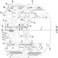
- FIG 10 shows a perspective view according to the first embodiment of the calibration and guide device in the production direction P, obliquely from below.
- a cooling gas extraction element 66 is attached to each carrier 51 of the adjustment units 49.
- the cooling gas extraction elements 66 each have two extraction nozzles 67, 68, which can be connected to extraction lines not shown here.
- the cooling gas extraction elements 66 are designed in the form of sheet metal housing structures, each of which has an opening on its underside for extracting cooling gas. On a side facing the tubular film 16, the cooling gas extraction elements 66 have a curved contour.
- the cooling gas extraction elements 66 are arranged between two lowest pairs of film guide elements 47 in the form of rollers, so that all film guide elements 47 located above them come into contact with the smallest possible proportion of outgassing from the film tube 16.
Landscapes
- Engineering & Computer Science (AREA)
- Mechanical Engineering (AREA)
- Physics & Mathematics (AREA)
- Thermal Sciences (AREA)
- Shaping By String And By Release Of Stress In Plastics And The Like (AREA)
Description
- Die Erfindung betrifft eine Vorrichtung zum Führen eines aus einem Folienblaskopf austretenden, in einer Produktionsrichtung abgezogenen Folienschlauchs, mit einem Rahmen, durch den der Folienschlauch in Produktionsrichtung hindurchführbar ist, und mehreren über den Umfang verteilt angeordnete Verstelleinheiten zum Verstellen von Folienführungselementen quer zur Produktionsrichtung. Die Verstelleinheiten weisen jeweils einen Schwenkarm, der am Rahmen schwenkbar befestigt ist, einen Träger für zumindest eines der Folienführungselemente, der mit dem Schwenkarm schwenkbar verbunden ist, und eine Koppelstange, die mit dem Träger schwenkbar verbunden ist, auf.
- Bei dem Herstellungsverfahren eines Folienschlauchs wird Kunststoffschmelze aus einem Extrusionswerkzeug mit Ringkanaldüse extrudiert und ausgezogen. Der plastifizierte, plastisch formbare und expandierbare heiße Folienschlauch wird unmittelbar nach dem Austritt aus dem Ringkanal am äußeren und häufig auch am inneren Umfang mit Kühlluft aus einem Kühlring bzw. einer Innenkühleinrichtung angeblasen und abgekühlt. Die Schlauchfolienblase wird in Längsrichtung über eine Vorrichtung zum Führen des Folienschlauchs (häufig auch als Führungsvorrichtung, Kalibriervorrichtung oder Kalibrierkorb bezeichnet) und eine Flachlegeeinrichtung geführt und in einer Abzugseinheit als Flachschlauch von Förderwalzen abgequetscht und abgezogen. Das sogenannte Einfrieren des Folienschlauchs, d. h. der Übergang der Kunststoffschmelze des Folienschlauchs von einem plastifiziertem und expandierbaren Zustand zu einem nicht mehr expandierbaren Zustand, erfolgt in der Regel dicht unterhalb der Kalibriervorrichtung. Die Kalibriervorrichtung weist über den Umfang verteilt angeordnete Folienführungselemente auf, die zum Führen des Folienschlauchs dienen. Die Folienführungselemente können beispielsweise Laufrollen aufweisen, die tangential an dem Folienschlauch anliegen und diesen führen. Die Folienführungselemente sind quer zu einer Produktionsrichtung des Folienschlauchs radialverstellbar und somit an unterschiedliche Durchmesser des Folienschlauchs anpassbaren.
- Eine Vorrichtung der eingangs genannten Art ist aus der
EP 1 967 350 A2 bekannt. Die dort beschriebene Führungsvorrichtung weist eine Trägerstruktur auf, an der mehrere bewegliche Arme schwenkbar befestigt sind. Die Arme tragen Führungsmittel, die in Kontakt mit dem Folienschlauch gehalten werden. Die bewegliche Arme bestehen aus einem gelenkigen Viereck und umfassen jeweils einen viereckigen Körper, der klappenähnlich an der Trägerstruktur schwenkbar angebracht ist, eine Gelenkstange, die mit einem Ende an der Trägerstruktur drehbar angebracht ist, und ein Trägerelement für die Führungsmittel, das an dem anderen Ende der Gelenkstange drehbar angebracht ist. Die beweglichen Arme sind derart angeordnet, dass die Führungsmittel immer tangential zum Folienschlauch gehalten werden. Die beweglichen Arme, die Gelenksstangen und die Trägerelemente sind jeweils derart an der Trägerstruktur und untereinander befestigt, dass sie eine trapezförmige Anordnung in der Art eines viergliedrigen Drehgelenkgetriebes bilden. - Verbindungsmittel, die die Gelenkstange mit dem Trägerelement verbinden, beschreiben beim Verstellen einen Kreisbogen um dasjenige Ende der Gelenkstange, das an der Trägerstruktur drehbar angebracht ist. Durch diese Anordnung werden Führungsmittel in Form von horizontal angeordneten drehbaren Laufrollen zwar tangential an den Folienschlauch gehalten. Die Positionierung der Laufrollen ist hierbei jedoch nur annähernd zentrisch zur Folienblase.
- Aus dem Stand der Technik sind ferner grundsätzlich berührende und berührungslose Kalibrier- und Führungsvorrichtungen bekannt, deren Folienführungselemente über verschiedenartige Verstelleinheiten an den jeweiligen Durchmesser des Folienschlauchs angepasst werden. Damit eine stufenlose Durchmesserverstellung möglich ist, sind die Folienführungselemente nach dem Stand der Technik auf dem Umfang in Kalibriersegmente aufgeteilt. Zur Durchmesserverstellung sind im Wesentlichen Schwenkarmmechanismen mit tangentialer Anschwenkung der Folienführungselemente und Hebel- bzw. Scheren-Mechanismen mit radial zentrischer Anstellung der Folienführungselemente bekannt.
- Scherenmechanismen, wie beispielsweise nach
EP 1 714 770 B1 oderEP 1 491 319 B1 , ermöglichen zwar eine radial zentrische Verstellung der Kalibriersegmente. Die indirekte lineare Stellbewegung unterliegt dabei aber bei konstanter Antriebsdrehzahl einer permanenten Änderung der Stellgeschwindigkeit, was speziell bei modernen Anlagen mit automatischer Ansteuerung der Durchmesserverstellung zu einem erhöhten Steuerungsaufwand führt. - Darüber hinaus sind Bauformen bekannt, bei denen Merkmale beider Systeme kombiniert werden, um bei einem Schwenkarmprinzip eine zentrische Anstellung über zusätzlich beischwenkbare Folienführungselemente zu ermöglichen, wie zum Beispiel in
EP 1 967 350 B1 ,EP 1 965 965 B1 ,EP 2 662 197 B1 ,US 3 980 418 A ,WO 2007/079899 A1 undWO 2016/139573 A1 gezeigt. - Eine Kalibriervorrichtung mit berührungslosen Folienführungselementen zeigt
EP 2 801 467 B1 . Dabei wird der Venturi- bzw. Bernoulli-Effekt genutzt, durch den eine mit ausreichender Geschwindigkeit tangential entlang einer der Schlauchfolie zugewandten Fläche des Führungselementes geführte Luftströmung eine ansaugende und fixierende Kraft auf ein ausreichend nah befindliches bewegliches Element, in diesem Fall die Schlauchfolie ausübt, ohne dass es zu einem berührenden Kontakt kommt. Die Schlauchfolie nimmt durch diese Kraft in Verbindung mit dem Luftpolster als Gegenkraft eine stabile Abstandsposition zum Folienführungselement ein. Die Folienführungselemente mit berührungsloser Luftpolsterführung können sowohl in Produktionsrichtung parallel beabstandet angeordnete Einzelelemente sein, als auch höhenversetzt gekreuzte Paare von Elementen in V-Stellung sein, die in Produktionsrichtung parallel beabstandet angeordnet sind. - Alle bekannten Bauformen weisen eine mechanische Synchronisation der am Umfang angeordneten Kalibriersegmente auf. Die Ausführungen nach
WO 2007/079899 A1 undWO 2016/139573 A1 haben eine direkte Kopplung der zusätzlich beischwenkbaren Folienführungselemente der jeweiligen Kalibriersegmente gemeinsam. Die dabei verwendeten Koppelelemente sind in einer Ebene teleskopierbar oder klappbar und in einer anderen Ebene starr und sorgen über den Verstellweg für eine gemeinsame tangentiale und zentrische Ausrichtung der Folienführungselemente zum Folienschlauch. - Die Koppelelemente weisen keine Verbindung zum äußeren starren Rahmen auf. Daher ist diese Ausführungsform bei größeren Bauformen schwierig beherrschbar und neigt zu Ungenauigkeit bei der Positionierung der Folienführungselemente zum Folienschlauch und zum Verkanten.
- Aufgabe der vorliegenden Erfindung ist es, eine Vorrichtung zum Führen eines aus einem Folienblaskopf austretenden, in einer Produktionsrichtung abgezogenen Folienschlauchs bereitzustellen, bei der Folienführungselemente möglichst präzise bei einer Änderung des Durchmessers des Folienschlauchs an diesen positioniert werden.
- Die Aufgabe wird durch eine Vorrichtung zum Führen eines aus einem Folienblaskopf austretenden, in einer Produktionsrichtung abgezogenen Folienschlauchs, mit den Merkmalen des Anspruchs 1 gelöst.
- Die durchmesserverstellbare Vorrichtung zum Führen des Folienschlauchs (Kalibrier- und Führungsvorrichtung) gemäß der Erfindung ermöglicht bei geringem baulichen Aufwand für jeden Durchmesser des Folienschlauchs eine präzise zentrische Anstellung der Folienführungselemente an den Folienschlauch. Hierzu dient insbesondere der Stellmechanismus, der zwischen der Koppelstange und dem Rahmen angeordnet ist und die Koppelstange mit dem Rahmen gelenkig verbindet.
- Durch die Anordnung des Stellmechanismus zwischen der Koppelstange und dem Rahmen lässt sich die Verstellung der Folienführungselemente relativ zum Folienschlauch präziser vorgeben, als dies beim Stand der Technik mit lediglich einer trapezförmige Anordnung der Verstelleinheit möglich ist.
- Die Koppelstange führt hierbei an dem mit dem Träger verbundenen Ende und an dem mit dem Stellmechanismus verbundenen Ende jeweils translatorische Bewegungen aus, die nicht deckungsgleich sind bzw. nicht deckungsgleiche Bewegungsvektoren aufweisen.
- Die Koppelstangen können einfache Stangen mit rundem, quadratischem oder rechteckigem Querschnitt sein. Sie können aber auch komplexer ausgeführt werden zum Beispiel als Frästeile, Drehteile, Stanzteile, Metallgussteile, Metallpressteile, Spritzgussteile, ausgelaserte Blechteile oder Blechkantteile.
- Die zumindest eine erste Verstelleinheit bildet ein ungleichmäßig übersetzendes Übertragungsgetriebe, nämlich ein Koppelgetriebe oder ein Kurvengetriebe. Diese beiden Getriebearten bieten die meisten Möglichkeiten an Strukturen und Eigenschaften, um eine präzise Ausrichtung der Folienführungselemente gegenüber dem Folienschlauch zu gewährleisten.
- In einer beispielhaften Ausgestaltung kann die zumindest eine erste Verstelleinheit ein sechsgliedriges Koppelgetriebe bilden. Hierbei ist die Komplexität des Getriebeaufbaus verhältnismäßig gering wobei eine hohe Präzision der Bewegungsabläufe und Anpassbarkeit an unterschiedliche Rahmenbedingungen ermöglicht wird. Das Koppelgetriebe kann hierbei insbesondere als Stephensonsche Kette ausgebildet sein.
- Der Stellmechanismus kann mit drei Elementen gekoppelt sein, nämlich mit dem Schwenkarm der zumindest einen ersten Verstelleinheit, mit der Koppelstange der zumindest einen ersten Verstelleinheit und mit dem Rahmen.
- Der Stellmechanismus kann ein Koppelelement aufweisen, das einerseits mit der Koppelstange der zumindest einen ersten Verstelleinheit und andererseits mit dem Rahmen jeweils gelenkig verbunden ist. "Gelenkig" bedeutet in diesem Zusammenhang, dass das Koppelelement jeweils mittels eines Drehgelenks für eine schwenkbare Verbindung, mittels eines Schubgelenks für eine verschiebbare Verbindung oder einer Kombination aus beidem mit der Koppelstange und dem Rahmen verbunden ist.
- In einer beispielhaften Ausgestaltung ist das Koppelelement mit der Koppelstange der zumindest einen ersten Verstelleinheit schwenkbar verbunden.
- Der Stellmechanismus kann ferner einen Verbindungshebel aufweisen, der einerseits mit dem Schwenkarm der zumindest einen ersten Verstelleinheit und andererseits mit dem Koppelelement der zumindest einen ersten Verstelleinheit schwenkbar verbunden ist. Alternativ ist es auch möglich, dass der Verbindungshebel anstatt mit dem Koppelelement mit der Koppelstange schwenkbar verbunden ist.
- Der Schwenkarm umfasst hierbei alle starr miteinander verbundenen Bauteile, die gleichförmig bewegt bzw. geschwenkt werden, insbesondere eine außerhalb einer Schwenkachse, um die der Schwenkarm am Rahmen schwenkbar befestigt ist, angeordnete Schwenkplatte zur Verbindung mit einem Antrieb.
- In einer weiteren beispielhaften Ausgestaltung kann das Koppelelement einerseits mit der Koppelstange der zumindest einen ersten Verstelleinheit verschiebbar und andererseits mit dem Rahmen schwenkbar verbunden sein.
- Hierbei kann der Stellmechanismus einen Kurvenführungsmechanismus mit einer Führung und einem Mitnehmer aufweisen, wobei die Koppelstange über den Kurvenführungsmechanismus mit dem Rahmen oder dem Schwenkarm gekoppelt ist und wobei der Mitnehmer entlang der Führung translatorisch bewegbar geführt ist.
- Der Mitnehmer kann an einem Element der Gruppe bestehend aus der Koppelstange und dem Rahmen und die Führung an dem anderen Element der Gruppe bestehend aus der Koppelstange und dem Rahmen angeordnet sein. Alternativ kann auch der Mitnehmer an einem Element der Gruppe bestehend aus der Koppelstange und dem Schwenkarm und die Führung an dem anderen Element der Gruppe bestehend aus der Koppelstange und dem Schwenkarm angeordnet sein.
- In beispielhafter Ausgestaltung kann der Mitnehmer mit der Koppelstange verbunden sein und die Führung am Rahmen angeordnet sein. Der Mitnehmer kann hierbei fest mit der Koppelstange verbunden sein oder als Schiebeelement ausgebildet sein, dass mit der Koppelstange schwenkbar oder drehbar verbunden ist. Der Mitnehmer kann ein einfacher Bolzen, eine Passschraube oder auch ein abrollendes Element wie beispielsweise ein Kugellager oder eine drehbar gelagerte Hülse sein. Natürlich kann der Mitnehmer bei einer komplexeren Ausführung der Koppelstange auch in die Koppelstange eingearbeitet sein.
- Die Führung kann hierbei eine kurvenförmige Laufbahn, zum Beispiel als Kurvenscheibe oder kurvenförmige Nut, ausgebildet sein.
- Die Führung, zum Beispiel in Form einer Kurvenscheibe, kann beispielsweise mittelbar oder unmittelbar am starren Rahmen angebaut sein. Die Kurvenscheibe kann auch Teil des starren Rahmens sein, d.h. die Laufbahn ist direkt in den starren Rahmen eingearbeitet.
- Es kann aber auch vorgesehen sein, dass die Führung bzw. die Kurvenscheibe am jeweiligen Schwenkarm eines der Verstelleinheiten angebaut ist bzw. Teil des Schwenkarm ist, d.h. die Laufbahn ist direkt in den Schwenkarm eingearbeitet.
- Wie bereits oben erläutert, gehört zum Schwenkarm auch eine außerhalb der Schwenkachse liegende Schwenkplatte zum Antreiben des Schwenkarms. Dabei ist es denkbar, dass die Laufbahn direkt in die Schwenkplatte eingearbeitet ist und die Schwenkplatte als Kurvenscheibe dient.
- Das Koppelelement kann Bestandteil eines Schubgelenks sein, das mittelbar oder unmittelbar am starren Rahmen drehbar angebaut ist. Ein vorderes Ende der Koppelstange ist mittelbar oder unmittelbar mit den beischwenkbaren Trägern für die Folienführungselemente verbunden und ein hinteres Ende der Koppelstange ist verschiebbar am Schubgelenk geführt.
- Vor oder hinter dem Schubgelenk kann die Koppelstange einen Mitnehmer aufweisen, der in die Laufbahn der zugehörigen Führung bzw. Kurvenscheibe greift und darin zwangsgeführt wird.
- Die vorgenannten Bauformen können alle auch derart in ihrer Anordnung umgekehrt werden, dass vor oder hinter dem Schubgelenk an der Koppelstange anstelle des Mitnehmers eine Kurvenscheibe angebaut wird. Die Kurvenscheibe kann bei einer komplexeren Ausführung der Koppelstange auch Teil der Koppelstange sein, d.h. die Laufbahn ist direkt in die Koppelstange eingearbeitet.
- Der in die Laufbahn der Kurvenscheibe greifende Mitnehmer ist dann am starren Rahmen oder am jeweiligen Schwenkarm der Verstelleinheit angebaut bzw. eingearbeitet.
- Bei einer Durchmesserverstellung der Kalibrier- und Führungsvorrichtung über die Schwenkarme der Verstelleinheit verändert sich der Winkel zwischen den Schwenkarmen und den zugehörigen Koppelstangen. Dadurch bewegt sich der Mitnehmer innerhalb der Laufbahn der Kurvenscheibe, oder bei umgekehrter Anordnung die Laufbahn der Kurvenscheibe entlang des Mitnehmers, sodass genau die für den angefahrenen Durchmesser notwendige Verschiebung der Koppelstange in Achsrichtung für eine exakt zentrische Ausrichtung der Folienführungselemente zum Folienschlauch erzeugt wird. Dabei verändert sich über den Verstellweg der Abstand vom vorderen Ende der Koppelstange bis zum drehbaren Schubgelenk. Das vordere Ende ist hierbei das mit dem Träger verbundene Ende der Koppelstange.
- Die Form der Laufbahn wird dabei so gestaltet, dass sich für jeden beliebigen Durchmesser der Kalibrier- und Führungsvorrichtung exakt der passende Schwenkwinkel für die Träger der Folienführungselemente einstellt.
- Die Vorrichtung kann ferner einen Synchronisationsmechanismus aufweisen, über den zur Synchronisation der Verstellbewegungen die Verstelleinheiten miteinander gekoppelt sind.
- Hierbei kann der Synchronisationsmechanismus Schubstangen aufweisen, über die die Verstelleinheiten über den Umfang der Vorrichtung umlaufend miteinander gekoppelt sind.
- Es kann vorgesehen sein, dass zumindest eine zweite Verstelleinheit der mehreren Verstelleinheiten ein Koppelelement aufweist, das einerseits mit der Koppelstange der zumindest einen zweiten Verstelleinheit und andererseits mit dem Rahmen gelenkig verbunden ist und im Übrigen frei von einer unmittelbaren Kopplung mit dem jeweiligen Stellarm ist. Hierbei kann der Synchronisationsmechanismus Schubstangen aufweisen, über die die Koppelelemente über den Umfang der Vorrichtung umlaufend miteinander gekoppelt sind.
- In einer Ausführungsform sind die an dem starren Rahmen angelenkten Schwenkarme für einen synchronen Schwenkvorgang miteinander umlaufend gekoppelt. Die gekoppelten Schwenkarme werden von einem gemeinsamen Antrieb bewegt, der einen linear oder rotatorisch wirkenden Stellaktor aufweist. Die umlaufende Kopplung wird vorzugsweise über ein einfaches und robustes Schubstangensystem gebildet. Es sind aber auch andere umlaufende Kopplungen wie beispielsweise ein Ketten- oder Zahnriementrieb denkbar. Das umlaufende Koppelsystem der Schwenkarme bildet zusammen mit dem Antrieb bzw. dem Stellaktor ein erstes bewegliches Stellsystem und realisiert die Durchmesserverstellung der Kalibrier- und Führungsvorrichtung. Ein zweites bewegliches Stellsystem dient zur durchmesserabhängigen Beischwenkung der Träger für die Folienführungselemente. Die Träger sind am freien Ende der Schwenkarme angebaut und um eine Schwenkachse parallel zur Produktionsrichtung drehbar gelagert.
- In einer abgewandelten Form erfolgt die Kopplung des ersten und zweiten beweglichen Stellsystems mittels des Stellmechanismus nur an einem der Schwenkarme und es werden zusätzlich die Koppelstangen untereinander umlaufend, zum Beispiel mittels Schubstangen, mechanisch synchron gekoppelt. Natürlich sind auch andere Kombinationen denkbar, beispielsweise die Kopplung mittels eines Stellmechanismus an jedem zweiten oder dritten der Schwenkarme mit einer synchronen mechanischen Kopplung der dazwischenliegenden Koppelstangen untereinander.
- Bei einer beispielhaften Ausführungsform ist das Antriebskonzept auch dahingehend umkehrbar, dass der linear oder rotatorisch wirkende Stellaktor Teil des zweiten beweglichen Stellsystems ist. Dabei ist aber bei konstanter Stellgeschwindigkeit des Stellaktors die sich ergebende Verstellgeschwindigkeit des Durchmessers nicht konstant. Ist eine konstante Verstellgeschwindigkeit gewünscht, zum Beispiel bei Anlagen mit in Regelkreisen automatisierter Durchmesserverstellung der Kalibrier- und Führungsvorrichtung, muss die Stellgeschwindigkeit des Aktors über den Durchmesser variiert werden.
- Die Folienführungselemente können sowohl in Produktionsrichtung parallel beabstandet angeordnete Einzelelemente aufweisen, als auch höhenversetzt gekreuzte Paare von Elementen in V-Stellung, die in Produktionsrichtung parallel beabstandet angeordnet sind.
- Die an den Trägern angebauten Folienführungselemente können beispielsweise gelagerte Laufrollen mit unterschiedlichen wärmeisolierenden oder antiadhäsiven Ummantelungen oder Beschichtungen sein. Es kann auch vorgesehen sein, dass der gesamte Laufrollenmantel aus einem wärmeisolierenden Werkstoff besteht, beispielsweise Kohlefaser. Die Folienführungselemente können auch starre Stangen mit einer Gleitbeschichtung sein (gerade oder zum Folienschlauch hin leicht gekrümmt). Die Folienführungselemente können auch starre Rundstangen sein, auf denen mehrere kurze ringförmige Körper aus einem wärmeisolierenden Werkstoff drehbar aufgereiht sind. Für eine berührungslose, absolut markierungsfreie Folienführung können die Folienführungselemente starre Balken sein (gerade oder zur Folienblase hin leicht gekrümmt), die ein Luftpolster bilden, welches den Folienschlauch ohne direkten Bauteilkontakt berührungslos führt.
- In einem Ausführungsbeispiel weisen die Träger jeweils zwei, beispielsweise länglich ausgebildete, Folienführungselemente, zum Beispiel in Form von Laufrollen oder Luftbalken, auf, die in Produktionsrichtung voneinander beabstandet und V-förmig überlappend angeordnet sind. Bei der Verwendung von Laufrollen oder ähnlichen berührenden Folienführungselementen, wie oben beschrieben, werden diese in Anlage zum Folienschlauch gehalten. Bei der Verwendung von Luftbalken werden diese so nah an dem Folienschlauch gehalten, dass diese den Folienschlauch durch den Venturi- bzw. Bernoulli-Effekt halten können. Da die beiden V-förmig zueinander angeordneten Folienführungselemente simultan durch eine der Verstelleinheiten bewegt werden, ist eine besonders präzise zentrische Ausrichtung der Folienführungselemente gegenüber dem Folienschlauch erforderlich, damit beide Folienführungselemente gleichmäßig in Anlage zum Folienschlauch oder nahe zu dieser gehalten sind.
- Bei allen vorher beschriebenen Ausführungsformen können die Schwenkarme in einer beispielhaften Bauform als zugeschnittene Formbleche mit stabilisierenden Aufkantungen ausgeführt sein. Entsprechend der Belastung wird dabei eine nach vorne zum Träger der Folienführungselemente abnehmende Querschnittshöhe gewählt.
- Bei allen vorher beschriebenen Ausführungsformen können zwischen, unterhalb oder oberhalb von Folienführungselementen Kühlgasabsaugelemente angebaut sein, die an den Verstelleinheiten angeordnet sind. Diese Kühlgasabsaugelemente sind vorzugsweise rohrförmig mit rundem oder eckigem Querschnitt oder als Blechgehäusekonstruktion ausgeführt und weisen vorzugsweise an ihrer inneren Kontur und/oder Unterseite eine oder mehrere Öffnungen zum Absaugen von Kühlgas auf, welches aus dem Kühlprozess in Produktionsrichtung entlang des Folienschlauchs strömt und mit öligen oder wachsartigen Monomeren belastet ist, die aus der heißen Schmelze ausgasen.
- Die innere Kontur der Kühlgasabsaugelemente kann gerade oder zur Schlauchfolie hin leicht gekrümmt ausgeführt sein, wobei der Krümmungsradius in etwa dem größten Radius der Schlauchfolie entspricht. Diese Krümmung kann auch durch mehrere Geradenabschnitte und entsprechende Knickwinkel angenähert sein. Die Kühlgasabsaugelemente sind vorzugsweise wie die Folienführungselemente am beischwenkbaren Träger angebaut und werden bei Verstellung des Durchmessers der Kalibrier- und Führungsvorrichtung zusammen mit den Folienführungselementen relativ zur Schlauchfolienblase bewegt. Damit ist für alle Durchmesser eine effektive Funktion der Kühlgasabsaugelemente gegeben.
- Die Wegführung des abgesaugten Kühlgases erfolgt über Schlauch- und Rohrleitungen über ein zentrales Absauggebläse. Ein partielles oder vollständiges Absaugen des belasteten Kühlgases oberhalb der Einfriergrenze im Bereich der Kalibrier- und Führungsvorrichtung verhindert bzw. reduziert eine Verschmutzung der nachfolgenden Anlagenkomponenten durch Ablagerung von Monomeren.
- Um auch die Kalibriervorrichtung selbst sauber zu halten, werden die Kühlgasabsaugelemente sinnvollerweise im unteren Bereich der Kalibrier- und Führungsvorrichtung angeordnet. Entsprechende Vorrichtungen zur Absaugung von Kühlgas sind nach dem Stand der Technik bekannt (beispielsweise nach
EP 1 491 319 B1 ). Ausführungsbeispiele von Vorrichtungen zum Führen eines aus einem Folienblaskopf austretenden, in einer Produktionsrichtung abgezogenen Folienschlauchs werden im Folgenden anhand der Figuren näher erläutert. Hierin zeigen: - Figur 1
- eine Gesamtansicht einer Folienblasanlage,
- Figur 2
- eine Draufsicht einer erste Ausführungsform einer Kalibrier- und Führungsvorrichtung,
- Figur 3
- eine Draufsicht der Kalibrier- und Führungsvorrichtung gemäß
Figur 2 , wobei der Folienschlauch einen gegenüber der Darstellung gemäßFigur 2 kleineren Durchmesser aufweist, - Figur 4
- eine Draufsicht einer zweiten Ausführungsform einer Kalibrier- und Führungsvorrichtung,
- Figur 5
- eine Draufsicht einer dritten Ausführungsform einer Kalibrier- und Führungsvorrichtung,
- Figur 6
- eine Teildraufsicht der Kalibrier- und Führungsvorrichtung gemäß
Figur 5 im Bereich einer der Verstelleinheiten, wobei der Träger und die Koppelstange der Verstelleinheit in verschiedenen Schwenkpositionen dargestellt sind, - Figur 7
- eine Draufsicht einer vierten Ausführungsform einer Kalibrier- und Führungsvorrichtung,
- Figur 8
- eine Draufsicht einer fünften Ausführungsform einer Kalibrier- und Führungsvorrichtung,
- Figur 9
- eine Draufsicht einer sechsten Ausführungsform einer Kalibrier- und Führungsvorrichtung, und
- Figur 10
- eine perspektivische Darstellung der Kalibrier- und Führungsvorrichtung gemäß der ersten Ausführungsform in Produktionsrichtung schräg von unten.
- In
Figur 1 ist in Seitenansicht und teilweise im Längsschnitt durch eine Längsachse eines Blasfolienschlauches eine Folienblasanlage zur Herstellung des Folienschlauchs gezeigt. Auf einem Maschinenfundament 11 steht ein Extruder 12, an dem zwei Aufgabetrichter 13, 14 für thermoplastisches Kunststoffmaterial zu erkennen sind. In Granulatform über die Trichter 13, 14 aufgegebenes thermoplastisches Kunststoffmaterial wird durch Druck und zusätzliche Heizmittel in einer Schnecke des Extruders 12 plastifiziert und homogenisiert und in einen sich an den Extruder anschließenden Blaskopf 15 mit vertikaler Achse gedrückt. Der Blaskopf 15 hat auf einer Oberseite eine nicht im Einzelnen gezeigt Ringdüse, aus der ein sich erweiternder achssymmetrischer Folienschlauch 16 aus zunächst noch plastifiziertem Folienmaterial austritt. Nach Erstarrung des Folienmaterial behält der Folienschlauch 16' seinen Durchmesser im Wesentlichen bei. Der Folienschlauch 16' wird in einer Flachlegevorrichtung 17 flach gedrückt und über ein Abziehwerk 18 nach oben abgezogen. Der flachgedrückte Folienschlauch 16" wird anschließend auf Coils aufgewickelt. In Richtung vom Blaskopf 15 zum Abziehwerk 18 werden die funktionellen Begriffe "vor" und "stromab von" derart verwendet, dass sie in räumlicher Beziehung "unter" und "oberhalb von" bedeuten. - Unmittelbar über dem Blaskopf 15 ist ein Kühlgasring 19 mit mehreren Gaszuleitungen 20 gezeigt. Der Kühlgasring 19 hat innenliegende Austrittsdüsen 21, aus denen das Kühlgas ausströmt und den Folienschlauch 16, der unter erhöhtem Innendruck steht, ringförmig im Wesentlichen wandparallel anströmt. Die Kühlgasströmung ist mit Pfeilen 22 symbolisiert. Der in diesem Bereich plastifizierte Folienschlauch 16 erweitert sich zunächst im Durchmesser unter dem genannten Überdruck im Inneren, bis er unter der Wirkung des Kühlgases erhärtet und konstanten Durchmesser annimmt. Der Ort des Übergangs vom plastifizierten Material zum erhärteten Material wird "Einfriergrenze" genannt und ist mit 23 bezeichnet.
- Oberhalb, d. h. in Abzugsrichtung stromab von der Einfriergrenze 23, befindet sich eine Kalibrier- und Führungsvorrichtung 24, die Folienführungselemente 47 mit übereinanderliegenden Laufrollenanordnungen enthält, die sich im Wesentlichen ringförmig um den Folienschlauch 16' legen. Um eine Anpassung an Folienschläuche unterschiedlichen Durchmessers zu ermöglichen, befinden sich hierbei die Laufrollenanordnungen in der Regel auf einzelnen Teilumfänge bildenden schwenkbaren Segmenten, mittels derer der Durchmesser der Kalibriervorrichtung verändert werden kann. Im Querschnitt können diese Segmente vereinfacht eine polygonförmige Kalibriervorrichtung bilden. Der noch relativ warme Folienschlauch 16' wird durch die Kalibrier- und Führungsvorrichtung 24 im Querschnitt stabilisiert und bezüglich des Einlaufs in die Flachlegeeinrichtung 17 zentriert. Die Kalibrier- und Führungsvorrichtung 24 kann relativ zum Blaskopf 15 höhenverstellbar angeordnet sein, um stets eine optimale Höhenposition relativ zur Einfriergrenze einnehmen zu können.
- Stromab von der Kalibrier- und Führungsvorrichtung 24 befindet sich ein Gasabsaugring 25 mit innenliegenden ringförmigen Ansaugöffnungen 26, der das mit Ausgasungen aus dem Folienschlauch belastete Kühlgas absaugen kann. An den Gasabsaugring 25 sind umfangsverteilt Absaugleitungen 27 angeschlossen. Das mit Ausgasungen belastete Kühlgas ist durch Pfeile 28 symbolisiert. Unmittelbar stromab vom Gasabsaugring 25 und mechanisch mit diesem verbunden liegt eine verstellbare Blende 29, die den Folienschlauch 16' abdichtend umschließt. Die Blende 29 ist über eine Verstellvorrichtung 30 im Öffnungsquerschnitt verstellbar und damit an verschiedene Durchmesser des Folienschlauchs 16' anpassbar. Durch das Abdichten des Folienschlauches oberhalb des Gasabsaugrings 25 wird verhindert, dass Reinluft aus einem Bereich stromab vom Gasabsaugring angesaugt wird, so dass die Absaugung des belasteten Kühlgases bei geringem Energieeinsatz optimiert ist.
- Im Bereich der Kalibrier- und Führungsvorrichtung 24 befindet sich alternativ oder zusätzlich radial außerhalb der Kalibrier- und Führungsvorrichtung ein weiterer Gasabsaugring oder eine Mehrzahl von einzelnen Gasabsaugtrichtern oder, wie beispielsweise gezeigt, Gasabsaugbalken 31, die mit einer Mehrzahl von über dem Umfang verteilten Absaugleitungen 33 verbunden sind. Hierbei kann zumindest ein Gasabsaugbalken oder mehrere übereinander angeordnete Gasabsaugbalken einem der zuvor genannten Segmente der Kalibriervorrichtung zugeordnet sein, so dass mit einer Anpassung der Kalibriervorrichtung an unterschiedliche Durchmesser des Folienschlauches 16' zugleich eine Anpassung der zusätzlichen Absaugvorrichtung an die unterschiedlichen Durchmesser erfolgen kann. Die Mehrzahl der Absaugleitungen 27 wird zunächst zu einer Leitung 27' zusammengeführt. Ebenso wird die Mehrzahl der Absaugleitungen 33 zu einer einzigen Leitung 33' zusammengeführt. Die Leitungen 27' und 33' werden dann zu einer einzigen Gasabsaugleitung 43 vereint, wobei eine Regelklappe 34 im Bereich eines Rohres 35 angeordnet ist. Bei Ausführungen ohne den oberen Gasabsaugring 25 entfällt die Zusammenführung und die Regelklappe 34, und die Leitung 33' geht unmittelbar in die Gasabsaugleitung 43 über. An die Absaugleitung 43 schließt sich ein Sauggebläse 44 an. In der Absaugleitung 43 kann vor oder nach dem Sauggebläse 44 ein Filter, beispielsweise ein Elektrofilter 45 integriert sein, wenn es aus Umweltschutzgründen unmöglich ist, die Absauggase in die Umgebung außerhalb einer Produktionshalle abzublasen. Anstelle des Elektrofilters 45 kann auch ein Kondensatabscheider vorgesehen sein, der strömungsmechanisch und/oder durch Abkühlung der Absauggase die darin enthaltenen belastenden Ausgasungen des Folienschlauchs abscheidet.
- Ein Steuergerät 36 mit Prozessor steuert über eine Steuerleitung 37 das Absauggebläse 44 sowie über eine Steuerleitung 38 ein weiteres Steuergerät 39 zur Ansteuerung der Verstellvorrichtung 30 für die Blende 29. Über eine Messleitung 40 werden die Signale eines Kühlgasmengenstromsensors 41 in den Kühlluftzuführungsleitungen 20 an das Steuergerät 36 übermittelt. Über eine Messleitung 42 werden Signale über die Druck- bzw. Mengenstromverhältnisse am Elektrofilter 45 zum Steuergerät 36 übermittelt. Das Steuergerät 36 kann über eine weitere Steuerleitung, die hier nicht dargestellt ist, auch das ebenfalls nicht dargestellte Kühlgasgebläse prozessorgesteuert regeln. Der gesamte Bereich vom ersten Kühlgasring 19 bis zum Gasabsaugring 25 ist von einer Einhausung 46 eingeschlossen, so dass das mit Ausgasungen belastete Kühlgas vom Arbeitsplatz des Bedienpersonals ferngehalten wird. Die Leitungen 27, 33 sind abgedichtet durch die Einhausung hindurchgeführt.
-
Figur 2 zeigt eine Draufsicht auf eine erste Ausführungsform einer Vorrichtung zum Führen eines aus einem Folienblaskopf austretenden, in einer Produktionsrichtung abgezogenen Folienschlauchs 16 (Kalibrier- und Führungsvorrichtung 24). Die Kalibrier- und Führungsvorrichtung 24 weist einen Rahmen 48 auf, an dem die nachfolgend beschriebenen beweglichen Elemente befestigt sind und der gegebenenfalls relativ zum Blaskopf höhenverstellbar angeordnet ist. Der Rahmen 48 bildet einen zentralen Durchgang, durch den der Folienschlauch 16 parallel zur Längsachse L bzw. in Richtung der Produktionsrichtung P gemäßFigur 1 hindurchgeführt ist. Über den Umfang sind 6 Verstelleinheiten 49 verteilt angeordnet. Die Verstelleinheiten 49 dienen zum Verstellen von Folienführungselementen 47 in einer Richtung radial zur Längsachse L. - Die Verstelleinheiten 49 weisen jeweils einen Schwenkarm 50 auf, der am Rahmen 48 schwenkbar befestigt ist. Der Schwenkarm 50 ist hierbei um eine Schwenkachse schwenkbar, die parallel zur Längsachse L angeordnet ist.
- Ferner weisen die Verstelleinheiten 49 jeweils einen Träger 51 auf, der in dem gezeigten Ausführungsbeispiel zwei Folienführungselemente 47 in Form von Laufrollen trägt, die in Produktionsrichtung voneinander beabstandet und V-förmig überlappend angeordnet sind. Der Träger 51 ist schwenkbar mit dem Schwenkarm 50 verbunden. Der Träger 51 ist hierbei um eine Schwenkachse schwenkbar mit dem Schwenkarm 50 verbunden, die parallel zur Längsachse L angeordnet ist.
- Ferner weisen die Verstelleinheiten 49 jeweils eine Koppelstange 52 auf, die mit dem Träger 51 schwenkbar verbunden ist.
- Letztendlich weisen die Verstelleinheiten 49 jeweils einen Stellmechanismus auf, mittels dessen die Koppelstange 52 gelenkig mit dem Rahmen 48 verbunden ist. In der in
Figur 2 dargestellten Ausführungsform umfasst der Stellmechanismus ein Koppelelement 53 sowie einen Verbindungshebel 54. Das Koppelelement 53 ist mit dem Rahmen 48, mit der Koppelstange 52 und mit dem Verbindungshebel 54 gelenkig verbunden. In dem gezeigten Ausführungsbeispiel ist das Koppelelement 53 jeweils schwenkbar mit dem Rahmen 48, der Koppelstange 52 und dem Verbindungshebel 54 verbunden. - Der Verbindungshebel 54 ist zudem mit dem Schwenkarm 50 schwenkbar verbunden. In dem gezeigten Ausführungsbeispiel ist der Schwenkarm 50 fest mit einer Schwenkplatte 55 verbunden, welche auf einer vom Träger 51 abgewandten Seite der Schwenkachse, um die der Schwenkarm 50 am Rahmen 48 schwenkbar befestigt ist, angeordnet ist. Der Verbindungshebel 54 ist mit der Schwenkplatte 55 unmittelbar schwenkbar verbunden. Der Verbindungshebel 54 ist somit über die Schwenkplatte 55 mit dem Schwenkarm 50 schwenkbar verbunden.
- An dem Rahmen 48 ist zudem ein Antrieb 56 befestigt. Der Antrieb 56 ist in Form eines Solenoids ausgebildet, mit dem ein Aktor 57 in Form einer Kolbenstange linear antreibbar ist. Hierbei ist der Aktor 57 mit der Schwenkplatte 55 einer der Verstelleinheiten 49 schwenkbar verbunden. Ferner ist ein Gehäuse des Antriebs 56 mit dem Rahmen 48 schwenkbar verbunden. Der Antrieb 56 stützt sich somit gegen den Rahmen 48 ab, wobei durch Verstellen des Aktors 57 der Schwenkarm 50 verschwenkt werden kann. Wird der Aktor 57 von der in
Figur 2 dargestellten eingeschobenen Position in die inFigur 3 dargestellte ausgeschobene Position überführt, wird der Schwenkarm 50, der mit dem Antrieb 56 verbunden ist, nach innen geschwenkt, sodass die Folienführungselemente 47 einen geringeren Durchmesser umschließen und somit einen Folienschlauch 16 mit kleinerem Durchmesser führen können. - Die Kalibrier- und Führungsvorrichtung 24 weist einen Synchronisationsmechanismus auf, um die Bewegung aller Verstelleinheiten 49 zu synchronisieren. Der Synchronisationsmechanismus weist Schubstangen 58 auf, die jeweils die Schwenkplatte 55 über den Umfang benachbarter Verstelleinheiten 49 miteinander koppeln. Hierzu sind die Schubstangen 58 jeweils mit den beiden Schwenkplatte 55 benachbarter Verstelleinheiten 49 schwenkbar verbunden. Somit wird die Schwenkbewegung derjenigen Verstelleinheit 49, die mit dem Antrieb 56 über die Schwenkplatte 55 verbunden ist, auf die übrigen Verstelleinheiten 49, die nicht unmittelbar mit dem Antrieb 56 verbunden sind, übertragen, sodass alle Verstelleinheiten 49 synchron bewegt werden.
-
Figur 4 zeigt eine zweite Ausführungsform einer Kalibrier- und Führungsvorrichtung 24, wobei Bauteile, die mit Bauteilen der ersten Ausführungsform übereinstimmen, mit denselben Bezugszeichen versehen sind und dort beschrieben sind. - Die Kalibrier- und Führungsvorrichtung 24 gemäß der zweiten Ausführungsform weist eine erste Verstelleinheit 59 und fünf zweite Verstelleinheiten 60 auf. Die erste Verstelleinheit 59 ist hinsichtlich ihrer Funktion und Kinematik identisch zu den Verstelleinheiten der Kalibrier- und Führungsvorrichtung gemäß der ersten Ausführungsform. Im Unterschied hierzu weist das Koppelelement 53 einen Hebelarm 61 auf, der sich bezogen auf eine Schwenkachse zwischen dem Koppelelement 53 und dem Verbindungshebel 54 auf einer von der Koppelstange 52 abgewandten Seite befindet. Der Hebelarm 61 ist hierbei integraler Bestandteil des Koppelelements 53.
- Die Koppelelemente 53 der zweiten Verstelleinheiten 60 sind vergleichbar zu dem Koppelelement 53 der ersten Verstelleinheit 59 ausgebildet. Im Unterschied zu der ersten Verstelleinheit 59 weisen die zweiten Verstelleinheiten 60 keinen Verbindungshebel 54 auf.
- Zur Synchronisierung der Bewegung der Schwenkarme 50 ist ein erster Synchronisationsmechanismus vorgesehen, der identisch zu dem Synchronisationsmechanismus der ersten Ausführungsform der Kalibrier- und Führungsvorrichtung ist. Darüber hinaus ist ein zweiter Synchronisationsmechanismus vorgesehen, der Schubstangen 62 aufweist, mittels derer die Koppelelemente 53 zweier über den Umfang benachbarter Verstelleinheiten 59, 60 miteinander gekoppelt werden. Alle Verstelleinheiten 59, 60 sind paarweise über den Umfang miteinander gekoppelt, sodass die Schwenkbewegung des Koppelelement 53 der ersten Verstelleinheit 59 auf alle zweiten Verstelleinheiten 60 synchron übertragen wird.
-
Figur 5 zeigt eine dritte Ausführungsform einer Kalibrier- und Führungsvorrichtung 24, wobei Bauteile, die mit Bauteilen der ersten Ausführungsform übereinstimmen, mit denselben Bezugszeichen versehen sind und dort beschrieben sind. - Im Unterschied zur ersten Ausführungsform sind die Koppelstange 52 der Verstelleinheiten 49 jeweils über das Koppelelement 53 drehgelenkig und verschiebbar mit dem Rahmen 48 verbunden. Das Koppelelement 53 ist drehbar mit dem Rahmen 48 verbunden. Die Koppelstange 52 ist verschiebbar mit dem Koppelelement 53 gekoppelt.
- Darüber hinaus ist jeweils an der Koppelstange 52 ein Mitnehmer 63 befestigt, der entlang einer Führung 64 am Rahmen 48 translatorisch bewegbar geführt ist. Die Führung 64 ist in dem gezeigten Ausführungsbeispiel eine Nut in einer Platte 65, die fest am Rahmen 48 befestigt ist. Es sind jedoch auch andere Führungssysteme denkbar. Die Führung 64 ist kurvenförmig gestaltet und derart angepasst, dass der Träger 51 stets zentrisch zur Längsachse L ausgerichtet ist, unabhängig vom Abstand zur Längsachse L bzw. zum Folienschlauch 16. Hierdurch wird eine präzise zentrische Ausrichtung der Folienführungselemente 47 in Form der beiden Laufrollen relativ zum Folienschlauch 16 gewährleistet, damit stets beide Laufrollen in Anlage zum Folienschlauch 16 gehalten sind.
- Das Koppelelement 53, der Mitnehmer 63 und die Führung 64 bilden zusammen den Stellmechanismus, über den die Koppelstange 52 mit dem Rahmen 48 verbunden ist.
- In der in
Figur 5 gezeigten dritten Ausführungsform befindet sich der Mitnehmer 63 an der Koppelstange 52 und die Führung 64 am Rahmen 48. Diese Anordnung kann auch umgekehrt vorgesehen sein, d. h. der Mitnehmer 63 kann an dem Rahmen 48 befestigt sein und die Führung 64 an der Koppelstange 52. -
Figur 6 zeigt eine Teildraufsicht der Kalibrier- und Führungsvorrichtung der dritten Ausführungsform gemäßFigur 5 im Bereich einer der Verstelleinheiten 49, wobei der Träger 51 und die Koppelstange 52 der Verstelleinheit 49 in verschiedenen Schwenkpositionen dargestellt ist. In einer maximal nach innen geschwenkten Schwenkposition, in der ein kleinster Durchmesser für den Folienschlauch 16 freigegeben wird, sind die Bauteile mit durchgezogenen Linien dargestellt. In von der maximal nach innen geschwenkten Schwenkpositionen abweichenden Schwenkpositionen sind die Bauteile mit strichpunktierten Linien dargestellt. - Der Träger 51 bildet in einer Ebene quer zur Längsachse L eine Mittelachse M, die unabhängig von der Schwenkposition der Verstelleinheit 49 durch die Mittelachse der Schlauchfolie bzw. durch die Längsachse L verläuft bzw. diese schneidet. In dem gezeigten Ausführungsbeispiel ist die Mittelachse M derart angeordnet, dass sie eine Schwenkachse, um die der Träger 51 schwenkbar mit dem Schwenkarm 50 verbunden ist, und eine weitere Schwenkachse, um die die Koppelstange 52 schwenkbar mit dem Träger 51 verbunden ist, verläuft. In
Figur 6 ist erkennbar, dass unabhängig von der Schwenkposition die Mittelachse M, M' stets durch die Längsachse L verläuft, wobei in der maximal nach außen geschwenkten Schwenkposition der Träger mit dem Bezugszeichen 51' und die Mittelachse mit dem Bezugszeichen M' versehen ist. - Darüber hinaus ist zu erkennen, wie der Mitnehmer 63 innerhalb der Führung 64 geführt ist. In der maximal nach innen geschwenkten Schwenkposition ist der Mitnehmer mit dem Bezugszeichen 63 und in der maximal nach außen geschwenkten Schwenkposition mit dem Bezugszeichen 63' versehen.
- Ferner ist der sich über die Schwenkposition verändernde Abstand zwischen dem Koppelelement 53 und die Mitnehmer 63 erkennbar. Dies ist darauf zurückzuführen, dass beim Schwenken des Schwenkarms 50 aus der maximal nach innen geschwenkten Schwenkposition in die maximal nach außen geschwenkten Schwenkposition die Koppelstange 52 nach außen durch das Koppelelement 53 geschoben wird. Daher ist der Abstand zwischen dem Koppelelement 53 und dem Mitnehmer 63 in der maximal nach innen geschwenkten Schwenkposition geringer als in der maximal nach außen geschwenkten Schwenkposition des Schwenkarms 50.
- Bei der dritten Ausführungsform befindet sich der Mitnehmer 63 auf einer vom Träger 51 abgewandten Seite des Koppelelements 53. Wie bei der in
Figur 7 gezeigten vierten Ausführungsform kann der Mitnehmer jedoch auch auf derselben Seite des Koppelelements 53 angeordnet sein, wie der Träger 51. Darüber hinaus ragt die Platte 65 mit der Führung 64 vom Rahmen 48 nach innen vor, und nicht, wie bei der dritten Ausführungsform gemäßFigur 5 nach außen. Im Übrigen entspricht die vierte Ausführungsform gemäßFigur 7 der dritten Ausführungsform gemäßFigur 5 . -
Figur 8 zeigt eine fünfte Ausführungsform einer Kalibrier- und Führungsvorrichtung 24, wobei Bauteile, die mit Bauteilen der dritten Ausführungsform gemäßFigur 5 übereinstimmen, mit denselben Bezugszeichen versehen sind und dort beschrieben sind. - Im Unterschied zu der dritten Ausführungsform ist die Führung 64 bzw. die Platte 65 nicht am Rahmen 48 sondern am Schwenkarm 50 befestigt. Die Platte 65 steht auf der Seite des Schwenkarms 50 vor, die der Koppelstange 52 zugewandt ist. Der Mitnehmer 63, der an der Koppelstange 52 befestigt ist, ist entlang der Führung 64 verschiebbar. Auch hier kann die Anordnung umgekehrt vorgesehen sein, d. h. der Mitnehmer 63 kann auch an dem Schwenkarm 50 angeordnet sein und die Führung 64 bzw. die Platte 65 mit der Koppelstange 52 verbunden sein, wie dies in
Figur 9 gemäß einer sechsten Ausführungsform gezeigt ist. -
Figur 10 zeigt eine perspektivische Darstellung gemäß der ersten Ausführungsform der Kalibrier- und Führungsvorrichtung in Produktionsrichtung P schräg von unten. Hierbei ist an jedem Träger 51 der Verstelleinheiten 49 ein Kühlgasabsaugelement 66 befestigt. Die Kühlgasabsaugelemente 66 weisen jeweils zwei Absaugstutzen 67, 68 auf, die mit hier nicht dargestellten Absaugleitungen verbunden werden können. In dem gezeigten Ausführungsbeispiel sind die Kühlgasabsaugelemente 66 in Form von Blechgehäuse-Konstruktionen ausgebildet, die jeweils an ihrer Unterseite eine Öffnung zum Absaugen von Kühlgas aufweisen. An einer zur Schlauchfolie 16 weisenden Seite weisen die Kühlgasabsaugelemente 66 eine gekrümmte Kontur auf. - Die Kühlgasabsaugelemente 66 sind zwischen zwei untersten Paaren von Folienführungselementen 47 in Form von Laufrollen angeordnet, sodass alle darüber liegenden Folienführungselemente 47 mit möglichst geringen Anteilen an Ausgasungen aus dem Folienschlauch 16 in Berührung kommen.
-
- 11
- Fundament
- 12
- Extruder
- 13
- Aufgabetrichter
- 14
- Aufgabetrichter
- 15
- Düsenkopf
- 16
- Folienschlauch
- 17
- Flachliegevorrichtung
- 18
- Abziehwerk
- 19
- Kühlgasring
- 20
- Kühlgaszuführung
- 21
- Kühlgasringdüse
- 22
- Kühlgas (Pfeil)
- 23
- Einfriergrenze
- 24
- Kalibrier- und Führungsvorrichtung
- 25
- Absaugring
- 26
- Absaugringdüse
- 27
- Gasabführung
- 28
- Abgas (Pfeil)
- 29
- Blende
- 30
- Verstellvorrichtung
- 31
- Gasabsaugbalken
- 32
- Absaugschlitz
- 33
- Gasabführung
- 34
- Regelklappe
- 35
- Rohr
- 36
- Steuergerät
- 37
- Steuerleitung
- 38
- Steuerleitung
- 39
- Steuergerät
- 40
- Messleitung
- 41
- Messfühler
- 42
- Messleitung
- 43
- Absaugleitung
- 44
- Sauggebläse
- 45
- Elektrofilter
- 46
- Einhausung
- 47
- Folienführungselemente
- 48
- Rahmen
- 49
- Verstelleinheit
- 50
- Schwenkarm
- 51
- Träger
- 52
- Koppelstange
- 53
- Koppelelement
- 54
- Verbindungshebel
- 55
- Schwenkplatte
- 56
- Antrieb
- 57
- Aktor
- 58
- Schubstange
- 59
- erste Verstelleinheit
- 60
- zweite Verstelleinheit
- 61
- Hebelarm
- 62
- Schubstange
- 63
- Mitnehmer
- 64
- Führung
- 65
- Platte
- 66
- Kühlgasabsaugelement
- 67
- Absaugstutzen
- 68
- Absaugstutzen
- L
- Längsachse
- M
- Mittelachse
- P
- Produktionsrichtung
Claims (15)
- Vorrichtung zum Führen eines aus einem Folienblaskopf austretenden, in einer Produktionsrichtung abgezogenen Folienschlauchs, miteinem Rahmen (48), durch den der Folienschlauch (16) in Produktionsrichtung (P) hindurchführbar ist, undmehreren über den Umfang verteilt angeordnete Verstelleinheiten (49, 59, 60) zum Verstellen von Folienführungselementen (47) quer zur Produktionsrichtung (P), wobei die Verstelleinheiten (49, 59, 60) jeweils Folgendes aufweisen: einen Schwenkarm (50), der am Rahmen (48) schwenkbar befestigt ist, einen Träger (51) für zumindest eines der Folienführungselemente (47), wobei der Träger (51) mit dem Schwenkarm (50) schwenkbar verbunden ist, und eine Koppelstange (52), die mit dem Träger (51) schwenkbar verbunden ist,dadurch gekennzeichnet,dass zumindest eine erste Verstelleinheit (49, 59) der mehreren Verstelleinheiten einen Stellmechanismus (53, 54, 63, 64, 65) aufweist, mittels dessen die Koppelstange (52) der zumindest einen ersten Verstelleinheit (49, 59) gelenkig mit dem Rahmen (48) verbunden ist, unddass die zumindest eine erste Verstelleinheit (49, 59) ein Koppelgetriebe oder ein Kurvengetriebe bildet.
- Vorrichtung nach Anspruch 1,
dadurch gekennzeichnet,
dass der Stellmechanismus (53, 54, 63, 64, 65) mit dem Schwenkarm (50) der zumindest einen ersten Verstelleinheit (49, 59), mit der Koppelstange (52) der zumindest einen ersten Verstelleinheit (49, 59) und mit dem Rahmen (48) gelenkig gekoppelt ist. - Vorrichtung nach Anspruch 1 oder 2,
dadurch gekennzeichnet,
dass der Stellmechanismus ein Koppelelement (53) aufweist, das einerseits mit der Koppelstange (52) der zumindest einen ersten Verstelleinheit (49, 59) und andererseits mit dem Rahmen (48) jeweils gelenkig verbunden ist. - Vorrichtung nach Anspruch 3,
dadurch gekennzeichnet,
dass das Koppelelement (53) mit der Koppelstange (52) der zumindest einen ersten Verstelleinheit (49, 59) schwenkbar verbunden ist. - Vorrichtung nach Anspruch 3 oder 4,
dadurch gekennzeichnet,
dass der Stellmechanismus einen Verbindungshebel (54) aufweist, der einerseits mit dem Schwenkarm (50) und andererseits mit dem Koppelelement (53) der zumindest einen ersten Verstelleinheit (49, 59) schwenkbar verbunden ist. - Vorrichtung nach Anspruch 3,
dadurch gekennzeichnet,
dass das Koppelelement (53) einerseits mit der Koppelstange (52) der zumindest einen ersten Verstelleinheit (49) verschiebbar und andererseits mit dem Rahmen (48) schwenkbar verbunden ist. - Vorrichtung nach Anspruch 6,
dadurch gekennzeichnet,
dass der Stellmechanismus einen Kurvenführungsmechanismus mit einer Führung (64) und einem Mitnehmer (63) aufweist, wobei die Koppelstange (52) über den Kurvenführungsmechanismus mit dem Rahmen (48) oder dem Schwenkarm (50) gekoppelt ist und wobei der Mitnehmer (63) entlang der Führung (64) translatorisch bewegbar geführt ist. - Vorrichtung nach Anspruch 7,
dadurch gekennzeichnet,
dass der Mitnehmer (63) an einem Element der Gruppe bestehend aus der Koppelstange (52) und dem Rahmen (48) und die Führung (64) an dem anderen Element der Gruppe bestehend aus der Koppelstange (52) und dem Rahmen (48) angeordnet ist. - Vorrichtung nach Anspruch 7,
dadurch gekennzeichnet,
dass der Mitnehmer (63) an einem Element der Gruppe bestehend aus der Koppelstange (52) und dem Schwenkarm (50) und die Führung (64) an dem anderen Element der Gruppe bestehend aus der Koppelstange (52) und dem Schwenkarm (50) angeordnet ist. - Vorrichtung nach einem der Ansprüche 1 bis 9,
dadurch gekennzeichnet,
dass die Vorrichtung ferner einen Synchronisationsmechanismus aufweist, über den zur Synchronisation der Verstellbewegungen die Verstelleinheiten (49, 59, 60) miteinander gekoppelt sind. - Vorrichtung nach Anspruch 10,
dadurch gekennzeichnet,
dass der Synchronisationsmechanismus Schubstangen (58, 62) aufweist, über die die Verstelleinheiten (49, 59, 60) über den Umfang der Vorrichtung umlaufend miteinander gekoppelt sind. - Vorrichtung nach Anspruch 10 oder 11,
dadurch gekennzeichnet,
dass zumindest eine zweite Verstelleinheit (60) der mehreren Verstelleinheiten (49, 59, 60) ein Koppelelement (53) aufweist, das einerseits mit der Koppelstange (52) der zumindest einen zweiten Verstelleinheit (60) und andererseits mit dem Rahmen (48) gelenkig verbunden ist und im Übrigen frei von einer unmittelbaren Kopplung mit dem jeweiligen Schwenkarm (50) ist, und dass der Synchronisationsmechanismus Schubstangen (62) aufweist, über die die Koppelelemente (53) der ersten Verstelleinheiten (59) und der zweiten Verstelleinheiten (60) über den Umfang der Vorrichtung umlaufend miteinander gekoppelt sind. - Vorrichtung nach einem der Ansprüche 1 bis 12,
dadurch gekennzeichnet,
dass die Träger (51) jeweils zwei Folienführungselemente (47) aufweisen, die in Produktionsrichtung voneinander beabstandet und V-förmig überlappend angeordnet sind. - Vorrichtung nach einem der Ansprüche 1 bis 13,
dadurch gekennzeichnet,
dass die Vorrichtung ferner Kühlgasabsaugelemente (66) aufweist, die an den Verstelleinheiten (49, 50, 60) angeordnet sind. - Vorrichtung nach Anspruch 14,
dadurch gekennzeichnet,
dass die Kühlgasabsaugelemente (66) in Produktionsrichtung (P) vor oder zwischen den Folienführungselementen (47) angeordnet sind.
Applications Claiming Priority (1)
| Application Number | Priority Date | Filing Date | Title |
|---|---|---|---|
| PCT/EP2019/064386 WO2020244737A1 (de) | 2019-06-03 | 2019-06-03 | Vorrichtung zum führen eines folienschlauchs |
Publications (2)
| Publication Number | Publication Date |
|---|---|
| EP3976338A1 EP3976338A1 (de) | 2022-04-06 |
| EP3976338B1 true EP3976338B1 (de) | 2024-09-25 |
Family
ID=66793976
Family Applications (1)
| Application Number | Title | Priority Date | Filing Date |
|---|---|---|---|
| EP19729229.5A Active EP3976338B1 (de) | 2019-06-03 | 2019-06-03 | Vorrichtung zum führen eines folienschlauchs |
Country Status (6)
| Country | Link |
|---|---|
| US (1) | US11975471B2 (de) |
| EP (1) | EP3976338B1 (de) |
| CN (1) | CN114206581B (de) |
| CA (1) | CA3142375C (de) |
| ES (1) | ES2996223T3 (de) |
| WO (1) | WO2020244737A1 (de) |
Families Citing this family (4)
| Publication number | Priority date | Publication date | Assignee | Title |
|---|---|---|---|---|
| JP2024093219A (ja) * | 2022-12-27 | 2024-07-09 | 住友重機械工業株式会社 | インフレーション成形装置 |
| EP4442427A1 (de) * | 2023-04-03 | 2024-10-09 | Kdesign GmbH | Folienblasanlage und verfahren zum regeln einer folienblasanlage |
| EP4725679A1 (de) | 2024-10-14 | 2026-04-15 | Kdesign GmbH | Temperiervorrichtung und folienblasanlage mit einer temperiervorrichtung |
| CN120003007B (zh) * | 2025-04-16 | 2025-07-18 | 四川益涵新材料科技有限公司 | 一种pe膜生产厚度均匀控制装置 |
Family Cites Families (25)
| Publication number | Priority date | Publication date | Assignee | Title |
|---|---|---|---|---|
| DE2207315A1 (de) * | 1972-02-17 | 1973-08-23 | Bodenseewerk Perkin Elmer Co | Peakdetektor |
| DE2357138C3 (de) * | 1973-11-15 | 1978-08-03 | Windmoeller & Hoelscher, 4540 Lengerich | Nachkühlvorrichtung für Blasfolien aus thermoplastischen Kunststoffen |
| US3980418A (en) * | 1975-09-05 | 1976-09-14 | Gloucester Engineering Co. Inc. | Guide assembly for air-expanded thermoplastic tubes |
| US4388061A (en) * | 1981-07-17 | 1983-06-14 | Macro Engineering Company Ltd. | Guide assembly for cylindrical plastic tubes |
| JPS5961916U (ja) * | 1982-10-18 | 1984-04-23 | 田口 武男 | 可変型バブル振れ止め装置 |
| DE3828259C1 (en) * | 1988-08-19 | 1990-03-08 | Windmoeller & Hoelscher, 4540 Lengerich, De | Calibrating device for supporting an extruded film tube |
| DE3835248A1 (de) * | 1988-10-15 | 1990-04-19 | Horn Heinz Dr Ing E H | Reckvorrichtung |
| US5441395A (en) * | 1994-06-22 | 1995-08-15 | Planeta; Mirek | Tubular plastic film extrusion apparatus with improved adjustable sizing cage |
| US6196827B1 (en) * | 1998-12-09 | 2001-03-06 | Pearl Technologies, Inc. | Swing arm stabilizing cage |
| ITMI20010897A1 (it) * | 2001-04-30 | 2002-10-30 | Odino Pontarolo | Rulli di guida per calibratori di estrusione di film plastici |
| DK1386719T3 (da) * | 2002-08-01 | 2008-10-20 | Reifenhaeuser Gmbh & Co Kg | Anordning til fremstilling af plastfolier |
| US6875002B2 (en) * | 2002-11-18 | 2005-04-05 | Pearl Technologies, Inc. | Oscillating guide cage |
| EP1491319B1 (de) | 2003-06-24 | 2008-01-02 | K Design GmbH | Verfahren und Vorrichtung zur Blasfolienherstellung |
| US7878227B2 (en) * | 2005-04-13 | 2011-02-01 | Peerless Chain Company | Debarking chain with passing links |
| ES2347570T3 (es) | 2005-04-22 | 2010-11-02 | Kdesign Gmbh | Cesta de calibrado para un tubo laminar. |
| US8210837B2 (en) | 2005-12-21 | 2012-07-03 | Windmoeller & Hoelscher Kg | Sizing cage adjustment |
| ITMI20070449A1 (it) * | 2007-03-06 | 2008-09-07 | Sanplast Di Santoro Raimondo | Dispositivo di guida per film plastici tubolari estrusi |
| DE102012103095B4 (de) * | 2012-04-11 | 2017-11-23 | Windmöller & Hölscher Kg | Führungsvorrichtung für die Führung einer Blasfolie |
| ITMI20120767A1 (it) | 2012-05-07 | 2013-11-08 | Sanplast Di Santoro Raimondo | Dispositivo di guida per film plastici tubolari estrusi integrante un sistema mobile di filtrazione fumi |
| EP2801467B1 (de) | 2013-05-08 | 2018-10-10 | Kdesign GmbH | Kalibriervorrichtung zum Kalibrieren eines extrudierten Folienschlauchs |
| EP3265289B1 (de) * | 2015-03-02 | 2019-05-08 | Syncro S.r.l. | Kalibrierkorb zur herstellung von blasfolien |
| WO2016193400A1 (de) * | 2015-06-03 | 2016-12-08 | Windmöller & Hölscher Kg | Führungseinrichtung und verfahren zum führen einer kunststofffolie sowie blasfolienanlage |
| US11077599B2 (en) * | 2015-06-08 | 2021-08-03 | Windmöller & Hölscher Kg | Calibrating device and method for calibrating a film tube |
| CN205310794U (zh) * | 2015-12-23 | 2016-06-15 | 瑞安市奥翔包装机械有限公司 | 双机头吹膜机的膜架机构 |
| CN108906496B (zh) * | 2018-09-11 | 2020-07-17 | 乐清市天美贸易有限公司 | 一种热固性塑料板胶接用涂胶装置及塑料板涂胶方法 |
-
2019
- 2019-06-03 EP EP19729229.5A patent/EP3976338B1/de active Active
- 2019-06-03 WO PCT/EP2019/064386 patent/WO2020244737A1/de not_active Ceased
- 2019-06-03 CN CN201980097189.1A patent/CN114206581B/zh active Active
- 2019-06-03 CA CA3142375A patent/CA3142375C/en active Active
- 2019-06-03 US US17/596,057 patent/US11975471B2/en active Active
- 2019-06-03 ES ES19729229T patent/ES2996223T3/es active Active
Also Published As
| Publication number | Publication date |
|---|---|
| WO2020244737A1 (de) | 2020-12-10 |
| CN114206581A (zh) | 2022-03-18 |
| US11975471B2 (en) | 2024-05-07 |
| CA3142375C (en) | 2023-10-03 |
| CA3142375A1 (en) | 2020-12-10 |
| US20220297368A1 (en) | 2022-09-22 |
| CN114206581B (zh) | 2024-03-01 |
| BR112021023586A2 (pt) | 2022-02-15 |
| EP3976338A1 (de) | 2022-04-06 |
| ES2996223T3 (en) | 2025-02-12 |
Similar Documents
| Publication | Publication Date | Title |
|---|---|---|
| EP1982819B1 (de) | Verfahren und Vorrichtung zur Kühlung eines Folienschlauches bei der Blasfolienherstellung | |
| EP2801467B1 (de) | Kalibriervorrichtung zum Kalibrieren eines extrudierten Folienschlauchs | |
| EP2604411B1 (de) | Vorrichtung zum Transportieren von Kunststoffvorformlingen | |
| EP2404735B1 (de) | Verfahren und Vorrichtung zum Anfahren einer Rohrextrusionslinie | |
| WO2020244737A1 (de) | Vorrichtung zum führen eines folienschlauchs | |
| EP3302927B1 (de) | Führungseinrichtung und verfahren zum führen einer kunststofffolie | |
| DE102016119872A1 (de) | Verfahren und Vorrichtung zur Regelung der Formstabilität eines Folienschlauchs bei dessen Herstellung mittels einer Blasfolienextrusionsanlage | |
| EP3093259A2 (de) | Pneumatisches verstellsystem | |
| DE4414977A1 (de) | Vorrichtung zur Herstellung von Rohren aus thermoplastischem Kunststoff mit Querprofilierung | |
| EP3231585A1 (de) | Vorichtung zum ultraschallschweissen | |
| WO2015107093A1 (de) | Verfahren und vorrichtung zum stützen eines kunststoffprofils | |
| EP3057765B1 (de) | Blasfolienanlage zum betreiben einer blasfolienanlage | |
| DE2903847C2 (de) | ||
| DE102018121387A1 (de) | Extrusionsvorrichtung mit innenliegender Kühlung | |
| EP2705941A1 (de) | Verfahren zur Herstellung blasgeformter Kunststoffhohlkörper und Mehrfachextrusionskopf zur Durchführung des Verfahrens | |
| DE102011002313A9 (de) | Extrusionswerkzeug zur Herstellung von flächigen Vorformlingen aus einer Kunststoffschmelze | |
| EP1923199B1 (de) | Vorrichtung zum Extrudieren von Hohlsträngen | |
| DE102007050938A1 (de) | Stufenlos einstellbare Kalibrierhülse für extrudierte Kunststoffrohre | |
| DE10230241B4 (de) | Verfahren und Vorrichtung zum maschinellen Einsetzen von Ventilkeilen in Federteller von Ventilen | |
| EP3956084B1 (de) | Setzkopf, blechpresse oder setzgerät mit diesem setzkopf sowie ein fügeverfahren eines fügeelements mit dem setzkopf | |
| AT526877A1 (de) | Extrusionskopf zur additiven Fertigung | |
| DE10150085B4 (de) | Vorrichtung zum Formen von Gewinden oder dergleichen Einformungen an Öffnungen von Behältern aus thermoplastischem Kunststoff | |
| EP2639042B1 (de) | Blasformsystem | |
| EP2626188A1 (de) | Verstellbare Kalibrierung | |
| EP4725679A1 (de) | Temperiervorrichtung und folienblasanlage mit einer temperiervorrichtung |
Legal Events
| Date | Code | Title | Description |
|---|---|---|---|
| STAA | Information on the status of an ep patent application or granted ep patent |
Free format text: STATUS: UNKNOWN |
|
| STAA | Information on the status of an ep patent application or granted ep patent |
Free format text: STATUS: THE INTERNATIONAL PUBLICATION HAS BEEN MADE |
|
| PUAI | Public reference made under article 153(3) epc to a published international application that has entered the european phase |
Free format text: ORIGINAL CODE: 0009012 |
|
| STAA | Information on the status of an ep patent application or granted ep patent |
Free format text: STATUS: REQUEST FOR EXAMINATION WAS MADE |
|
| 17P | Request for examination filed |
Effective date: 20211201 |
|
| AK | Designated contracting states |
Kind code of ref document: A1 Designated state(s): AL AT BE BG CH CY CZ DE DK EE ES FI FR GB GR HR HU IE IS IT LI LT LU LV MC MK MT NL NO PL PT RO RS SE SI SK SM TR |
|
| DAV | Request for validation of the european patent (deleted) | ||
| DAX | Request for extension of the european patent (deleted) | ||
| REG | Reference to a national code |
Ref country code: DE Ipc: B29C0048900000 Ref legal event code: R079 Ref document number: 502019012191 Country of ref document: DE Free format text: PREVIOUS MAIN CLASS: B29C0048000000 |
|
| GRAP | Despatch of communication of intention to grant a patent |
Free format text: ORIGINAL CODE: EPIDOSNIGR1 |
|
| STAA | Information on the status of an ep patent application or granted ep patent |
Free format text: STATUS: GRANT OF PATENT IS INTENDED |
|
| RIC1 | Information provided on ipc code assigned before grant |
Ipc: B29C 55/28 20060101ALI20240531BHEP Ipc: B29C 48/10 20190101ALI20240531BHEP Ipc: B29C 48/90 20190101AFI20240531BHEP |
|
| INTG | Intention to grant announced |
Effective date: 20240618 |
|
| GRAS | Grant fee paid |
Free format text: ORIGINAL CODE: EPIDOSNIGR3 |
|
| GRAA | (expected) grant |
Free format text: ORIGINAL CODE: 0009210 |
|
| STAA | Information on the status of an ep patent application or granted ep patent |
Free format text: STATUS: THE PATENT HAS BEEN GRANTED |
|
| AK | Designated contracting states |
Kind code of ref document: B1 Designated state(s): AL AT BE BG CH CY CZ DE DK EE ES FI FR GB GR HR HU IE IS IT LI LT LU LV MC MK MT NL NO PL PT RO RS SE SI SK SM TR |
|
| REG | Reference to a national code |
Ref country code: GB Ref legal event code: FG4D Free format text: NOT ENGLISH |
|
| REG | Reference to a national code |
Ref country code: CH Ref legal event code: EP |
|
| REG | Reference to a national code |
Ref country code: DE Ref legal event code: R096 Ref document number: 502019012191 Country of ref document: DE |
|
| REG | Reference to a national code |
Ref country code: IE Ref legal event code: FG4D Free format text: LANGUAGE OF EP DOCUMENT: GERMAN |
|
| REG | Reference to a national code |
Ref country code: LT Ref legal event code: MG9D |
|
| PG25 | Lapsed in a contracting state [announced via postgrant information from national office to epo] |
Ref country code: NO Free format text: LAPSE BECAUSE OF FAILURE TO SUBMIT A TRANSLATION OF THE DESCRIPTION OR TO PAY THE FEE WITHIN THE PRESCRIBED TIME-LIMIT Effective date: 20241225 |
|
| REG | Reference to a national code |
Ref country code: DE Ref legal event code: R082 Ref document number: 502019012191 Country of ref document: DE Representative=s name: NEUMANN MUELLER OBERWALLENEY PATENTANWAELTE PA, DE |
|
| PG25 | Lapsed in a contracting state [announced via postgrant information from national office to epo] |
Ref country code: GR Free format text: LAPSE BECAUSE OF FAILURE TO SUBMIT A TRANSLATION OF THE DESCRIPTION OR TO PAY THE FEE WITHIN THE PRESCRIBED TIME-LIMIT Effective date: 20241226 Ref country code: FI Free format text: LAPSE BECAUSE OF FAILURE TO SUBMIT A TRANSLATION OF THE DESCRIPTION OR TO PAY THE FEE WITHIN THE PRESCRIBED TIME-LIMIT Effective date: 20240925 |
|
| PG25 | Lapsed in a contracting state [announced via postgrant information from national office to epo] |
Ref country code: BG Free format text: LAPSE BECAUSE OF FAILURE TO SUBMIT A TRANSLATION OF THE DESCRIPTION OR TO PAY THE FEE WITHIN THE PRESCRIBED TIME-LIMIT Effective date: 20240925 |
|
| PG25 | Lapsed in a contracting state [announced via postgrant information from national office to epo] |
Ref country code: LV Free format text: LAPSE BECAUSE OF FAILURE TO SUBMIT A TRANSLATION OF THE DESCRIPTION OR TO PAY THE FEE WITHIN THE PRESCRIBED TIME-LIMIT Effective date: 20240925 |
|
| PG25 | Lapsed in a contracting state [announced via postgrant information from national office to epo] |
Ref country code: RS Free format text: LAPSE BECAUSE OF FAILURE TO SUBMIT A TRANSLATION OF THE DESCRIPTION OR TO PAY THE FEE WITHIN THE PRESCRIBED TIME-LIMIT Effective date: 20241225 |
|
| REG | Reference to a national code |
Ref country code: NL Ref legal event code: MP Effective date: 20240925 |
|
| PG25 | Lapsed in a contracting state [announced via postgrant information from national office to epo] |
Ref country code: RS Free format text: LAPSE BECAUSE OF FAILURE TO SUBMIT A TRANSLATION OF THE DESCRIPTION OR TO PAY THE FEE WITHIN THE PRESCRIBED TIME-LIMIT Effective date: 20241225 Ref country code: NO Free format text: LAPSE BECAUSE OF FAILURE TO SUBMIT A TRANSLATION OF THE DESCRIPTION OR TO PAY THE FEE WITHIN THE PRESCRIBED TIME-LIMIT Effective date: 20241225 Ref country code: LV Free format text: LAPSE BECAUSE OF FAILURE TO SUBMIT A TRANSLATION OF THE DESCRIPTION OR TO PAY THE FEE WITHIN THE PRESCRIBED TIME-LIMIT Effective date: 20240925 Ref country code: GR Free format text: LAPSE BECAUSE OF FAILURE TO SUBMIT A TRANSLATION OF THE DESCRIPTION OR TO PAY THE FEE WITHIN THE PRESCRIBED TIME-LIMIT Effective date: 20241226 Ref country code: FI Free format text: LAPSE BECAUSE OF FAILURE TO SUBMIT A TRANSLATION OF THE DESCRIPTION OR TO PAY THE FEE WITHIN THE PRESCRIBED TIME-LIMIT Effective date: 20240925 Ref country code: BG Free format text: LAPSE BECAUSE OF FAILURE TO SUBMIT A TRANSLATION OF THE DESCRIPTION OR TO PAY THE FEE WITHIN THE PRESCRIBED TIME-LIMIT Effective date: 20240925 |
|
| REG | Reference to a national code |
Ref country code: ES Ref legal event code: FG2A Ref document number: 2996223 Country of ref document: ES Kind code of ref document: T3 Effective date: 20250212 |
|
| PG25 | Lapsed in a contracting state [announced via postgrant information from national office to epo] |
Ref country code: NL Free format text: LAPSE BECAUSE OF FAILURE TO SUBMIT A TRANSLATION OF THE DESCRIPTION OR TO PAY THE FEE WITHIN THE PRESCRIBED TIME-LIMIT Effective date: 20240925 |
|
| PG25 | Lapsed in a contracting state [announced via postgrant information from national office to epo] |
Ref country code: PT Free format text: LAPSE BECAUSE OF FAILURE TO SUBMIT A TRANSLATION OF THE DESCRIPTION OR TO PAY THE FEE WITHIN THE PRESCRIBED TIME-LIMIT Effective date: 20250127 Ref country code: IS Free format text: LAPSE BECAUSE OF FAILURE TO SUBMIT A TRANSLATION OF THE DESCRIPTION OR TO PAY THE FEE WITHIN THE PRESCRIBED TIME-LIMIT Effective date: 20250125 |
|
| PG25 | Lapsed in a contracting state [announced via postgrant information from national office to epo] |
Ref country code: RO Free format text: LAPSE BECAUSE OF FAILURE TO SUBMIT A TRANSLATION OF THE DESCRIPTION OR TO PAY THE FEE WITHIN THE PRESCRIBED TIME-LIMIT Effective date: 20240925 Ref country code: SM Free format text: LAPSE BECAUSE OF FAILURE TO SUBMIT A TRANSLATION OF THE DESCRIPTION OR TO PAY THE FEE WITHIN THE PRESCRIBED TIME-LIMIT Effective date: 20240925 |
|
| PG25 | Lapsed in a contracting state [announced via postgrant information from national office to epo] |
Ref country code: EE Free format text: LAPSE BECAUSE OF FAILURE TO SUBMIT A TRANSLATION OF THE DESCRIPTION OR TO PAY THE FEE WITHIN THE PRESCRIBED TIME-LIMIT Effective date: 20240925 |
|
| PG25 | Lapsed in a contracting state [announced via postgrant information from national office to epo] |
Ref country code: PL Free format text: LAPSE BECAUSE OF FAILURE TO SUBMIT A TRANSLATION OF THE DESCRIPTION OR TO PAY THE FEE WITHIN THE PRESCRIBED TIME-LIMIT Effective date: 20240925 |
|
| PG25 | Lapsed in a contracting state [announced via postgrant information from national office to epo] |
Ref country code: SK Free format text: LAPSE BECAUSE OF FAILURE TO SUBMIT A TRANSLATION OF THE DESCRIPTION OR TO PAY THE FEE WITHIN THE PRESCRIBED TIME-LIMIT Effective date: 20240925 |
|
| REG | Reference to a national code |
Ref country code: DE Ref legal event code: R097 Ref document number: 502019012191 Country of ref document: DE |
|
| PG25 | Lapsed in a contracting state [announced via postgrant information from national office to epo] |
Ref country code: DK Free format text: LAPSE BECAUSE OF FAILURE TO SUBMIT A TRANSLATION OF THE DESCRIPTION OR TO PAY THE FEE WITHIN THE PRESCRIBED TIME-LIMIT Effective date: 20240925 |
|
| PLBE | No opposition filed within time limit |
Free format text: ORIGINAL CODE: 0009261 |
|
| STAA | Information on the status of an ep patent application or granted ep patent |
Free format text: STATUS: NO OPPOSITION FILED WITHIN TIME LIMIT |
|
| 26N | No opposition filed |
Effective date: 20250626 |
|
| PG25 | Lapsed in a contracting state [announced via postgrant information from national office to epo] |
Ref country code: SE Free format text: LAPSE BECAUSE OF FAILURE TO SUBMIT A TRANSLATION OF THE DESCRIPTION OR TO PAY THE FEE WITHIN THE PRESCRIBED TIME-LIMIT Effective date: 20240925 |
|
| PGFP | Annual fee paid to national office [announced via postgrant information from national office to epo] |
Ref country code: ES Payment date: 20250718 Year of fee payment: 7 |
|
| PGFP | Annual fee paid to national office [announced via postgrant information from national office to epo] |
Ref country code: IT Payment date: 20250630 Year of fee payment: 7 |
|
| PG25 | Lapsed in a contracting state [announced via postgrant information from national office to epo] |
Ref country code: HR Free format text: LAPSE BECAUSE OF FAILURE TO SUBMIT A TRANSLATION OF THE DESCRIPTION OR TO PAY THE FEE WITHIN THE PRESCRIBED TIME-LIMIT Effective date: 20240925 |
|
| REG | Reference to a national code |
Ref country code: CH Ref legal event code: H13 Free format text: ST27 STATUS EVENT CODE: U-0-0-H10-H13 (AS PROVIDED BY THE NATIONAL OFFICE) Effective date: 20260127 |
|
| PG25 | Lapsed in a contracting state [announced via postgrant information from national office to epo] |
Ref country code: MC Free format text: LAPSE BECAUSE OF FAILURE TO SUBMIT A TRANSLATION OF THE DESCRIPTION OR TO PAY THE FEE WITHIN THE PRESCRIBED TIME-LIMIT Effective date: 20240925 |
|
| PG25 | Lapsed in a contracting state [announced via postgrant information from national office to epo] |
Ref country code: LU Free format text: LAPSE BECAUSE OF NON-PAYMENT OF DUE FEES Effective date: 20250603 |
|
| REG | Reference to a national code |
Ref country code: BE Ref legal event code: MM Effective date: 20250630 |
|
| PG25 | Lapsed in a contracting state [announced via postgrant information from national office to epo] |
Ref country code: IE Free format text: LAPSE BECAUSE OF NON-PAYMENT OF DUE FEES Effective date: 20250603 |
|
| PG25 | Lapsed in a contracting state [announced via postgrant information from national office to epo] |
Ref country code: BE Free format text: LAPSE BECAUSE OF NON-PAYMENT OF DUE FEES Effective date: 20250630 |
|
| PG25 | Lapsed in a contracting state [announced via postgrant information from national office to epo] |
Ref country code: CH Free format text: LAPSE BECAUSE OF NON-PAYMENT OF DUE FEES Effective date: 20250630 |
|
| PG25 | Lapsed in a contracting state [announced via postgrant information from national office to epo] |
Ref country code: LT Free format text: LAPSE BECAUSE OF FAILURE TO SUBMIT A TRANSLATION OF THE DESCRIPTION OR TO PAY THE FEE WITHIN THE PRESCRIBED TIME-LIMIT Effective date: 20240925 |
|
| PGFP | Annual fee paid to national office [announced via postgrant information from national office to epo] |
Ref country code: GB Payment date: 20260623 Year of fee payment: 8 |
|
| PGFP | Annual fee paid to national office [announced via postgrant information from national office to epo] |
Ref country code: DE Payment date: 20260623 Year of fee payment: 8 |
|
| PGFP | Annual fee paid to national office [announced via postgrant information from national office to epo] |
Ref country code: CZ Payment date: 20260521 Year of fee payment: 8 Ref country code: TR Payment date: 20260601 Year of fee payment: 8 |
|
| PGFP | Annual fee paid to national office [announced via postgrant information from national office to epo] |
Ref country code: FR Payment date: 20260622 Year of fee payment: 8 |
|
| PG25 | Lapsed in a contracting state [announced via postgrant information from national office to epo] |
Ref country code: AT Free format text: LAPSE BECAUSE OF NON-PAYMENT OF DUE FEES Effective date: 20250603 Ref country code: CY Free format text: LAPSE BECAUSE OF FAILURE TO SUBMIT A TRANSLATION OF THE DESCRIPTION OR TO PAY THE FEE WITHIN THE PRESCRIBED TIME-LIMIT Effective date: 20240925 |