EP3975813B1 - A cleaner head for a vacuum cleaner - Google Patents
A cleaner head for a vacuum cleaner Download PDFInfo
- Publication number
- EP3975813B1 EP3975813B1 EP20721706.8A EP20721706A EP3975813B1 EP 3975813 B1 EP3975813 B1 EP 3975813B1 EP 20721706 A EP20721706 A EP 20721706A EP 3975813 B1 EP3975813 B1 EP 3975813B1
- Authority
- EP
- European Patent Office
- Prior art keywords
- agitator
- cleaner head
- air outlet
- cleaner
- suction cavity
- Prior art date
- Legal status (The legal status is an assumption and is not a legal conclusion. Google has not performed a legal analysis and makes no representation as to the accuracy of the status listed.)
- Active
Links
Images


Classifications
-
- A—HUMAN NECESSITIES
- A46—BRUSHWARE
- A46B—BRUSHES
- A46B13/00—Brushes with driven brush bodies or carriers
- A46B13/001—Cylindrical or annular brush bodies
- A46B13/006—Cylindrical or annular brush bodies formed by winding a strip tuft in a helix about the body
-
- A—HUMAN NECESSITIES
- A47—FURNITURE; DOMESTIC ARTICLES OR APPLIANCES; COFFEE MILLS; SPICE MILLS; SUCTION CLEANERS IN GENERAL
- A47L—DOMESTIC WASHING OR CLEANING; SUCTION CLEANERS IN GENERAL
- A47L9/00—Details or accessories of suction cleaners, e.g. mechanical means for controlling the suction or for effecting pulsating action; Storing devices specially adapted to suction cleaners or parts thereof; Carrying-vehicles specially adapted for suction cleaners
- A47L9/02—Nozzles
- A47L9/04—Nozzles with driven brushes or agitators
- A47L9/0405—Driving means for the brushes or agitators
- A47L9/0411—Driving means for the brushes or agitators driven by electric motor
-
- A—HUMAN NECESSITIES
- A47—FURNITURE; DOMESTIC ARTICLES OR APPLIANCES; COFFEE MILLS; SPICE MILLS; SUCTION CLEANERS IN GENERAL
- A47L—DOMESTIC WASHING OR CLEANING; SUCTION CLEANERS IN GENERAL
- A47L9/00—Details or accessories of suction cleaners, e.g. mechanical means for controlling the suction or for effecting pulsating action; Storing devices specially adapted to suction cleaners or parts thereof; Carrying-vehicles specially adapted for suction cleaners
- A47L9/02—Nozzles
- A47L9/04—Nozzles with driven brushes or agitators
- A47L9/0427—Gearing or transmission means therefor
- A47L9/0444—Gearing or transmission means therefor for conveying motion by endless flexible members, e.g. belts
-
- A—HUMAN NECESSITIES
- A47—FURNITURE; DOMESTIC ARTICLES OR APPLIANCES; COFFEE MILLS; SPICE MILLS; SUCTION CLEANERS IN GENERAL
- A47L—DOMESTIC WASHING OR CLEANING; SUCTION CLEANERS IN GENERAL
- A47L9/00—Details or accessories of suction cleaners, e.g. mechanical means for controlling the suction or for effecting pulsating action; Storing devices specially adapted to suction cleaners or parts thereof; Carrying-vehicles specially adapted for suction cleaners
- A47L9/02—Nozzles
- A47L9/04—Nozzles with driven brushes or agitators
- A47L9/0455—Bearing means therefor
-
- A—HUMAN NECESSITIES
- A47—FURNITURE; DOMESTIC ARTICLES OR APPLIANCES; COFFEE MILLS; SPICE MILLS; SUCTION CLEANERS IN GENERAL
- A47L—DOMESTIC WASHING OR CLEANING; SUCTION CLEANERS IN GENERAL
- A47L9/00—Details or accessories of suction cleaners, e.g. mechanical means for controlling the suction or for effecting pulsating action; Storing devices specially adapted to suction cleaners or parts thereof; Carrying-vehicles specially adapted for suction cleaners
- A47L9/02—Nozzles
- A47L9/04—Nozzles with driven brushes or agitators
- A47L9/0461—Dust-loosening tools, e.g. agitators, brushes
- A47L9/0466—Rotating tools
- A47L9/0477—Rolls
-
- A—HUMAN NECESSITIES
- A47—FURNITURE; DOMESTIC ARTICLES OR APPLIANCES; COFFEE MILLS; SPICE MILLS; SUCTION CLEANERS IN GENERAL
- A47L—DOMESTIC WASHING OR CLEANING; SUCTION CLEANERS IN GENERAL
- A47L9/00—Details or accessories of suction cleaners, e.g. mechanical means for controlling the suction or for effecting pulsating action; Storing devices specially adapted to suction cleaners or parts thereof; Carrying-vehicles specially adapted for suction cleaners
- A47L9/02—Nozzles
- A47L9/06—Nozzles with fixed, e.g. adjustably fixed brushes or the like
- A47L9/0666—Nozzles with fixed, e.g. adjustably fixed brushes or the like with tilting, floating or similarly arranged brushes, combs, lips or pads
Definitions
- the present invention relates to a cleaner head for a vacuum cleaner.
- a vacuum cleaner typically comprises a main body containing dirt and dust separating apparatus, a cleaner head connected to the main body and having an opening, and a motor-driven fan unit for drawing dirt-bearing air through the opening and the cleaner head, and into the main body.
- the opening is directed downwardly to face the floor surface to be cleaned.
- the dirt-bearing air is conveyed to the separating apparatus so that dirt and dust can be separated from the air before the air is expelled to the atmosphere.
- the separating apparatus can include one or more of a filter, a filter bag and a cyclonic arrangement.
- a driven agitator usually in the form of a brush bar, may be rotatably mounted within a suction cavity of the cleaner head.
- the brush bar typically comprises an elongate cylindrical core bearing bristles which extend radially outward from the core.
- the opening is in the form of an aperture, usually an elongate, rectangular aperture, defined by a sole plate located on the base of the cleaner head.
- the brush bar may be mounted within the suction cavity so that the bristles protrude by a small extent through the opening.
- the brush bar is activated mainly when the vacuum cleaner is used to clean carpeted surfaces.
- Rotation of the brush bar may be driven by an electric motor powered by a power supply derived from the main body of the vacuum cleaner, or by a turbine driven by an air flow passing through or into the cleaner head.
- the brush bar may be driven by the motor via a drive belt, or may be driven directly by the motor, so as to rotate within the suction cavity. Rotation of the brush bar causes the bristles to sweep along the surface of the carpet, agitating both the fibres of the carpet and any dust or other detritus located on the surface of the carpet and/or between fibres of the carpet, and resulting in a significant amount of energy being imparted to the dust.
- the rotating bristles sweep dust rearwardly through the opening and into the suction cavity.
- the suction of air causes air to flow underneath the sole plate and around the brush bar to help lift the dirt and dust from the surface of the carpet and then carry it from the opening through the cleaner head towards the separating apparatus.
- GB 513 909A discloses a machine for surfacing floors.
- the machine includes a body and a surfacing drum at one end of the body.
- the surfacing drum is conical in shape so that the machine can work close up to the skirting board.
- GB 364 362A discloses a vacuum cleaner for cleaning carpets.
- the vacuum cleaner has a beating member rotatably mounted within a suction nozzle.
- the beating member is of substantially elliptical cross section and may be twisted.
- the beating member may be provided with bristles having conical bores.
- the suction cavity comprises an air outlet located adjacent the free end of the agitator.
- the agitator may comprise a conical core having helical ridges upstanding from an external conical surface of the core, and a row of bristles located between the helical ridges.
- the row of bristles may comprise a continuous row of bristles, or it may comprise a plurality of discrete bristle tufts.
- the bristles may be mounted on a flexible bristle base which is inserted between the upstanding ridges of the core.
- the bristles may be arranged so as to bend freely, for example, against the upper surfaces of the helical ridges, as debris becomes wrapped around the agitator. This can further encourage the migration of the debris towards the free end of the agitator.
- the cleaner head preferably comprises a bottom surface, or sole plate, in which the opening is formed.
- the longitudinal axis of the agitator is preferably inclined at an acute angle to a plane containing the opening of the cleaner head. In a preferred embodiment the acute angle is 7°, whereas in another embodiment the acute angle is 5°.
- the lowermost portion of the external surface of the core is preferably parallel to the plane containing the opening so that the lowermost portion of the external surface of the core is evenly spaced along its length from this plane.
- the opening is preferably trapezoidal in shape.
- the opening may be defined by a relatively long leading edge, and relatively long trailing edge, and two side edges each extending between the leading edge and the trailing edge.
- the leading edge may be perpendicular to the side edges, or, as in a preferred embodiment, it may be inclined relative to the side edges so that it subtends an acute angle with one side edge and an obtuse angle with the other side edge.
- the suction cavity is preferably defined by a conical housing of the cleaner head.
- the housing may be formed from a plurality of housing sections.
- the housing preferably has substantially the same shape as the agitator.
- a housing section may be pivotable relative to the sole plate as the cleaner head is manoeuvred over a floor surface. This can reduce the risk of the sole plate becoming lifted away from the floor surface as it is manoeuvred over the floor surface, and so reducing the suction of the cleaner head.
- the airflow path is preferably defined, at least in part, by a neck for conveying air from the air outlet to the outlet of the cleaner head.
- the neck preferably comprises a connector for connecting the cleaner head to a vacuum cleaner.
- the airflow path is also preferably defined, at least in part, by a duct for conveying air from the air outlet to an air inlet port formed in the neck.
- the duct, and thus the airflow path preferably extends externally of the housing from the air outlet to the neck.
- the duct is preferably curved, and preferably curves through 90° between the air outlet and the air inlet port.
- the duct may have a constant or a varying radius of curvature along its length.
- the duct is preferably integral with at least part of the neck and/or at least part of the housing.
- the second airflow path is preferably defined, at least in part, by a duct for conveying air from the second air outlet to an air inlet port formed in the neck and from which the second part of the airflow enters the first part of the airflow.
- the air inlet port is located between the first air outlet and the outlet of the cleaner head. The second airflow path thus extends away from the suction cavity in parallel to the portion of the first airflow path located upstream from the air inlet port.
- the cleaner head preferably comprises an agitator engaging member for pressing against the agitator any debris which has become wrapped around the agitator.
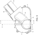
- FIGS 1 to 5 are external views of a first embodiment of a cleaner head 10 for a vacuum cleaner.
- the cleaner head 10 comprises a conical front housing 12, a rear housing 14 connected to the front housing 12, and a sole plate 16 connected to the front housing 12.
- One or more of the rear housing 14 and the sole plate 16 may be integral with the front housing 12, and are preferably formed from plastics material. In use, the sole plate 16 is placed upon the floor surface to be cleaned.
- the front housing 12 defines a conical suction cavity 34 which receives the airflow drawn into the cleaner head 10 through the suction opening 22.
- the suction cavity 34 houses an agitator 36 for agitating the fibres of a carpeted floor surface.
- the agitator 36 is in the form of a brush bar which is rotatable relative to the front housing 12, and suction cavity 34, about an axis which is collinear with the longitudinal axis of the agitator 36.
- the agitator 36 comprises a hollow core 38, which in this embodiment is conical in shape.
- a pair of helical ridges 46, 48 are upstanding from the external surface 40 of the core 38, and extend helically along the external surface 40 of the core 38 from the second end 44 to the first end 42 thereof.
- the ridges 46, 48 extend substantially the entire length of the core 38, and extend about the external surface 40 by around 450°.
- the ridges 46, 48 are preferably integral with the core 38 so that the ridges 46, 48 do not deform excessively upon contact with a floor surface.
- the ridges 46, 48 define a helical channel 50 therebetween which receives a bristle strip 52 (not shown in Figure 4 ).
- the bristle strip 52 comprises a flexible bristle base 54 and a row of bristles 56 woven into the bristle strip 54.
- Such debris is encouraged by the conical shape of the agitator 136 to migrate along the length of the agitator 136 from the second end 144 towards the first end 142. Under the action of the engaging member 196, such debris is pressed around the agitator 136 until it falls from the first end 412 of the agitator 136, whereupon the released debris becomes entrained within the airflow and passes through the duct 192 and into the neck 184 of the cleaner head 10.
- the inclination of the bristles 156 relative to the external surface 140 of the core 138 encourages the wrapped debris to migrate along the agitator 136.
Landscapes
- Engineering & Computer Science (AREA)
- Mechanical Engineering (AREA)
- Nozzles For Electric Vacuum Cleaners (AREA)
Description
- The present invention relates to a cleaner head for a vacuum cleaner.
- A vacuum cleaner typically comprises a main body containing dirt and dust separating apparatus, a cleaner head connected to the main body and having an opening, and a motor-driven fan unit for drawing dirt-bearing air through the opening and the cleaner head, and into the main body. The opening is directed downwardly to face the floor surface to be cleaned. The dirt-bearing air is conveyed to the separating apparatus so that dirt and dust can be separated from the air before the air is expelled to the atmosphere. The separating apparatus can include one or more of a filter, a filter bag and a cyclonic arrangement.
- A driven agitator, usually in the form of a brush bar, may be rotatably mounted within a suction cavity of the cleaner head. The brush bar typically comprises an elongate cylindrical core bearing bristles which extend radially outward from the core. The opening is in the form of an aperture, usually an elongate, rectangular aperture, defined by a sole plate located on the base of the cleaner head. The brush bar may be mounted within the suction cavity so that the bristles protrude by a small extent through the opening.
- The brush bar is activated mainly when the vacuum cleaner is used to clean carpeted surfaces. Rotation of the brush bar may be driven by an electric motor powered by a power supply derived from the main body of the vacuum cleaner, or by a turbine driven by an air flow passing through or into the cleaner head. The brush bar may be driven by the motor via a drive belt, or may be driven directly by the motor, so as to rotate within the suction cavity. Rotation of the brush bar causes the bristles to sweep along the surface of the carpet, agitating both the fibres of the carpet and any dust or other detritus located on the surface of the carpet and/or between fibres of the carpet, and resulting in a significant amount of energy being imparted to the dust. With the brush bar rotating in such a direction that the bristles move from the front edge of the opening towards the rear edge, the rotating bristles sweep dust rearwardly through the opening and into the suction cavity. The suction of air causes air to flow underneath the sole plate and around the brush bar to help lift the dirt and dust from the surface of the carpet and then carry it from the opening through the cleaner head towards the separating apparatus.
- During the passage of agitated dust through the dirty air inlet, long strands of debris, for example hair or thread or the like, may become wrapped around the brush bar or a mounting thereof. This may lead to an increased torque on the brush bar, and a sufficient build-up of strands of debris on the brush bar may lead to failure of the brush bar and a reduced pick-up performance.
-
GB 513 909A -
WO 2017/064462 A1 discloses a cleaner head for a vacuum cleaner including an agitator driven by a turbine assembly. The turbine assembly includes an impeller, a transmission, a shaft connecting the impeller to the transmission and a wall located between the impeller and the transmission, where the wall includes an aperture through which the shaft passes. The shaft has a stepped section and a spring biases a shoulder of the stepped section against the wall to occlude the aperture. This helps to ensure that the transmission and the impeller are effectively sealed from any pressure differentials to reduce the amount of lubricant or grease drawn from the transmission. The turbine assembly further includes an overspeed device with a traveling part having a conical surface. -
GB 364 362A - In a first aspect, the present invention provides a cleaner head for a vacuum cleaner, the cleaner head comprising:
- a suction cavity comprising an opening through which debris enters the cleaner head, and an air outlet; and
- an agitator mounted in the suction cavity in a cantilevered manner for rotation relative thereto, the agitator being conical in shape and having a first, free end and a second end which has a larger diameter than the first end;
- wherein the air outlet is located adjacent the free end of the agitator.
- During the use of the cleaner head, any debris which has become wrapped around the agitator is encouraged by the conical shape of the agitator to migrate along the agitator towards the free end, where it can become released from the agitator. In order to minimise the risk of this released debris becoming re-wrapped around the agitator before it is conveyed away from the agitator within an airflow which is passing through the suction cavity, the suction cavity comprises an air outlet located adjacent the free end of the agitator. An airflow, into which debris which has been released from the agitator generally becomes entrained, passes along an airflow path extending from the air outlet towards an outlet of the cleaner head.
- As used herein, the term "conical shape" includes both conical and frustoconical shapes. The cone angle of a conical shape is the angle subtended between the longitudinal axis of the conical shape and the external conical surface of the conical shape. In one preferred embodiment, the cone angle is 7°, whereas in another preferred embodiment, the cone angle is 5°.
- As used herein the term "debris" refers to strands which have the potential to wrap around the agitator during operation of the cleaner head. For example, debris may be considered to comprise strands having a length which is greater than the maximum circumference of the agitator. Examples of debris include hairs, threads and other relatively long fibres and strands.
- The agitator may comprise a conical core having helical ridges upstanding from an external conical surface of the core, and a row of bristles located between the helical ridges. The row of bristles may comprise a continuous row of bristles, or it may comprise a plurality of discrete bristle tufts. The bristles may be mounted on a flexible bristle base which is inserted between the upstanding ridges of the core. The bristles may be arranged so as to bend freely, for example, against the upper surfaces of the helical ridges, as debris becomes wrapped around the agitator. This can further encourage the migration of the debris towards the free end of the agitator. For example, the bristles may be formed from relatively thin strands of nylon or carbon fibre. As measured in a direction perpendicular to the longitudinal axis of the core, the height of the upstanding ridges is preferably at least 50% of the height of the bristles. This can prevent the debris from sinking between the bristles towards the core of the agitator and so becoming trapped within the row of bristles.
- The cleaner head preferably comprises a bottom surface, or sole plate, in which the opening is formed. The longitudinal axis of the agitator is preferably inclined at an acute angle to a plane containing the opening of the cleaner head. In a preferred embodiment the acute angle is 7°, whereas in another embodiment the acute angle is 5°. In use, the lowermost portion of the external surface of the core is preferably parallel to the plane containing the opening so that the lowermost portion of the external surface of the core is evenly spaced along its length from this plane. The opening is preferably trapezoidal in shape. The opening may be defined by a relatively long leading edge, and relatively long trailing edge, and two side edges each extending between the leading edge and the trailing edge. The leading edge may be perpendicular to the side edges, or, as in a preferred embodiment, it may be inclined relative to the side edges so that it subtends an acute angle with one side edge and an obtuse angle with the other side edge.
- The suction cavity is preferably defined by a conical housing of the cleaner head. The housing may be formed from a plurality of housing sections. The housing preferably has substantially the same shape as the agitator. A housing section may be pivotable relative to the sole plate as the cleaner head is manoeuvred over a floor surface. This can reduce the risk of the sole plate becoming lifted away from the floor surface as it is manoeuvred over the floor surface, and so reducing the suction of the cleaner head.
- As mentioned above, the air outlet is located adjacent the free end of the agitator. In one embodiment, the air outlet is located rearwardly of the agitator so that the air outlet lies directly behind the free end. In another embodiment, the air outlet is positioned such that any plane arranged orthogonal to the longitudinal axis of the agitation which intersects the air outlet does not also intersect the agitator. In other words, the air outlet is positioned so that, in a direction extending along the longitudinal axis of the agitator, the air outlet is spaced from the free end of the agitator. This can improve the capture of debris released from the agitator within the airflow drawn from the suction cavity, The spacing of the air outlet from the agitator along this direction is preferably less than 10mm, more preferably less than 5mm.
- The airflow path is preferably defined, at least in part, by a neck for conveying air from the air outlet to the outlet of the cleaner head. The neck preferably comprises a connector for connecting the cleaner head to a vacuum cleaner. The airflow path is also preferably defined, at least in part, by a duct for conveying air from the air outlet to an air inlet port formed in the neck. The duct, and thus the airflow path, preferably extends externally of the housing from the air outlet to the neck. To minimise turbulence, the duct is preferably curved, and preferably curves through 90° between the air outlet and the air inlet port. The duct may have a constant or a varying radius of curvature along its length. To facilitate manufacture, the duct is preferably integral with at least part of the neck and/or at least part of the housing.
- In one embodiment, the air outlet provides the sole air outlet from the suction cavity. In another embodiment, the suction cavity also comprises an additional air outlet. During the use of this cleaner head, a first part of the airflow passing through the suction cavity leaves the suction cavity through the additional air outlet, and a second part of this airflow leaves the suction cavity through the air outlet located adjacent the free end of the agitator. The first part of the airflow, generally containing dust and other detritus which has been agitated from a floor surface by the agitator, passes along a first airflow path extending from the additional air outlet, hereafter referred to as the first air outlet, to an outlet of the cleaner head. The second part of the airflow, into which debris which has been released from the agitator generally becomes entrained, passes along a second airflow path which preferably extends from the air outlet located adjacent the free end of the agitator, hereafter referred to as the second air outlet, towards the first airflow path so as to merge with the first part of the airflow between the first air outlet and the outlet of the cleaner head.
- The cleaner head may include:
- a suction cavity comprising an opening through which debris enters the cleaner head, and a first air outlet; and
- an agitator mounted in the suction cavity in a cantilevered manner for rotation relative thereto, the agitator being conical in shape and having a first, free end and a second end which has a larger diameter than the first end;
- wherein the suction cavity comprises a second air outlet located adjacent the free end of the agitator, and the cleaner head defines a first airflow path extending downstream of the suction cavity from the first air outlet towards an outlet of the cleaner head, and a second airflow path extending downstream of the suction cavity
- Each of the first air outlet and the second air outlet is preferably located rearwardly of the agitator. As mentioned above, the second air outlet is located adjacent the free end of the agitator, whereas the first air outlet is preferably located midway between the free end and the second end of the agitator. Where the agitator comprises a helical row of bristles, we have found that these locations of the first and second air outlets, and thus the directions in which air passes through the suction cavity, can encourage debris to wrap around the agitator in a direction which is generally orthogonal to the longitudinal axis of the agitator, as opposed to a direction extending generally along or alongside the helical row of bristles. This can promote the migration of debris along the agitator and its subsequent release from the agitator.
- The first air outlet and the second air outlet are preferably spaced in a direction extending parallel to the longitudinal axis of the agitator.
- The first airflow path is preferably defined, at least in part, by a neck for conveying air from the first air outlet to the outlet of the cleaner head. The neck preferably comprises a connector for connecting the cleaner head to a vacuum cleaner. The first part of the airflow and the second part of the airflow preferably merge within the neck.
- As aforementioned, the second airflow path is preferably defined, at least in part, by a duct for conveying air from the second air outlet to an air inlet port formed in the neck and from which the second part of the airflow enters the first part of the airflow. The air inlet port is located between the first air outlet and the outlet of the cleaner head. The second airflow path thus extends away from the suction cavity in parallel to the portion of the first airflow path located upstream from the air inlet port.
- The cleaner head preferably comprises a single conical agitator which has a free end located adjacent to, but spaced from a side wall of the suction cavity, and a second end, located opposite to free end, which has a larger diameter than the free end. The agitator is preferably mounted, at or towards the second end of the agitator, to a drive for driving the rotation of the agitator relative to the suction cavity. The drive preferably comprises a motor located externally of the agitator, and a belt connecting the agitator to the motor. Alternatively, the motor may be located within the agitator. To maximise cleaning performance by preventing released debris from becoming trapped between the free end of the agitator and the side wall of the housing, the spacing between the free end of the agitator and the side wall is preferably in the range from 2 to 20 mm. In one embodiment, where the second air outlet is located directly behind the free end of the agitator, the spacing is in the range from 3 to 5mm, whereas in another embodiment, where the second air outlet is spaced from the free end of the agitator along the longitudinal axis of the agitator, the spacing is in the range from 10 to 20mm.
- As the cleaner head is manoeuvred over a carpeted floor surface, a portion of the carpet can become raised and drawn into the suction cavity through the opening, in view of the relatively low air pressure generated within the suction cavity by the vacuum cleaner. This can cause the raised portion of the carpet to contact the agitator, in particular the bristles and the helical ridges upstanding from the external surface of the core. When debris has become wrapped around the agitator, the action of the carpet pressing upon the agitator can encourage this debris to become more tightly wrapped around the agitator. We have observed that tightly wrapping the debris around the agitator can promote its migration towards the free end of the agitator.
- So as not to be reliant upon the movement of carpet into the suction cavity to urge debris against the agitator, to promote migration of the wrapped debris along the agitator the cleaner head preferably comprises an agitator engaging member for pressing against the agitator any debris which has become wrapped around the agitator.
- The engaging member preferably extends substantially the entire length of the agitator. With rotation of the agitator within the suction cavity, this enables the engaging member to press against substantially the entire length of the row of bristles and the ridges of the core. The engaging member preferably extends in a direction which is inclined at the cone angle to the longitudinal axis of the agitator. This can allow the engaging member to be aligned relative to the agitator so that it lies substantially parallel to a portion, preferably an upper portion of the external surface of the core of the agitator. This can enable the engaging member to apply a substantially uniform force to the agitator along its length. The engaging member may be mounted on any surface of the cleaner head so as to engage the agitator. In one embodiment, the engaging member is mounted on an inner wall of the housing so as to be located within the suction chamber. The engaging member may be located adjacent the suction opening of the cleaner head, or located opposite to the suction opening. The engaging member may extend partially about the longitudinal axis of the agitator.
- As mentioned above, the bristles may be arranged so as to bend freely as debris becomes wrapped around the agitator so as to further encourage the migration of the debris towards the free end of the agitator. These bristles may be mounted on the bristle base so as to extend substantially perpendicular to the bristle base. As debris becomes wrapped around the agitator, the bristles flex towards an upper end of an upstanding ridge of the core, and/or so as to at least partially overlie adjacent bristles.
- As an alternative, the bristles may be inclined relative to the bristle base, and thus relative to the external surface of the core, in a direction extending towards the free end of the core. This can reduce the risk of any wrapped debris becoming lodged between adjacent bristles and not migrating towards the bristle base, and so can further promote the migration of wrapped threads towards the free end of the agitator.
- The row of bristles extends in a row direction, and the bristles are preferably inclined at an acute angle to, and towards, the row direction. The row of bristles may be formed by securing the bristles to the flexible bristle base, and using a hot rolling technique to angle the bristles towards the bristle base. The row of bristles is then inserted between the ridges of the core so that the row of bristles adopts a helical shape which extends towards the free end of the core in a helical direction, and so that the bristles are inclined towards the free end of the core at an acute angle to the helical direction. The acute angle is preferably in the range from 20 to 60°, more preferably in the range from 30 to 50°.
- Features described above in connection with the first aspect of the invention are equally applicable to the second aspect of the invention, and vice versa.
- Preferred features of the invention will now be described, by way of example only, with reference to the accompanying drawings, in which:
-
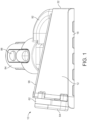
Figure 1 is a front view of a first embodiment of a cleaner head for a vacuum cleaner; -
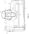
Figure 2 is a top view of the cleaner head ofFigure 1 ; -
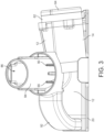
Figure 3 is a rear view of the cleaner head ofFigure 1 ; -
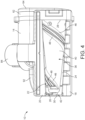
Figure 4 is a bottom view of the cleaner head ofFigure 1 ; -
Figure 5 is a side view of the cleaner head ofFigure 1 ; -
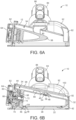
Figure 6(a) is a sectional view taken along line A-A ofFigure 5 , andFigure 6(b) is a sectional view taken along line B-B ofFigure 5 ; -
Figure 7(a) is a front view of the core of an agitator of the cleaner head ofFigure 1 ,Figure 7(b) is an end view of the agitator ofFigure 7(a), Figure 7(c) is a side view of a row of bristles of the agitator, andFigure 7(d) is a sectional view taken along line J-J inFigure 7(a) but with the row of bristles located on the core; -
Figure 8(a) is a front view of the cleaner head ofFigure 1 ,Figure 8(b) is a similar view toFigure 8(a) but with all components removed except an agitator engaging member of the cleaner head, andFigure 8(c) is a sectional view taken along line M-M ofFigure 8(b) ; -
Figure 9 is a front view of a second embodiment of a cleaner head for a vacuum cleaner; -
Figure 10 is a top view of the cleaner head ofFigure 9 ; -
Figure 11 is a side view of the cleaner head ofFigure 9 ; -
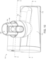
Figure 12 is a bottom view of the cleaner head ofFigure 9 ; -
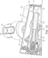
Figure 13 is a sectional view taken along line A-A ofFigure 10 ; -
Figure 14 is a sectional view taken along line D-D ofFigure 10 ; and -
Figure 15 is part of a sectional view taken along line B-B ofFigure 9 . -
Figures 1 to 5 are external views of a first embodiment of acleaner head 10 for a vacuum cleaner. Thecleaner head 10 comprises a conicalfront housing 12, arear housing 14 connected to thefront housing 12, and a sole plate 16 connected to thefront housing 12. One or more of therear housing 14 and the sole plate 16 may be integral with thefront housing 12, and are preferably formed from plastics material. In use, the sole plate 16 is placed upon the floor surface to be cleaned. - With particular reference to
Figure 4 , the sole plate 16 comprises a leadingsection 18 and a trailingsection 20 located on opposite sides of asuction opening 22 through which an airflow is drawn into thecleaner head 10. Thesuction opening 22 is generally trapezoidal in shape, and is delimited by afront working edge 24, arear working edge 26 which is inclined relative to thefront working edge 24, a relatively longfirst side edge 28 and a relatively short,second side edge 30 which is parallel to thefirst side edge 28. The front workingedge 24 is defined by the intersection of the leadingsection 18 of the sole plate 16 with thefront housing 12, and therear working edge 26 is defined by the intersection of the trailingsection 20 of the sole plate 16 with thefront housing 12. The working edges 24, 26 agitate the fibres of a carpeted floor surface as the cleaner head is manoeuvred over such a surface. Thesecond side edge 30 is defined by the bottom end of aside wall 32 of thefront housing 12. - With reference also to
Figures 6(a) and 6(b) , thefront housing 12 defines aconical suction cavity 34 which receives the airflow drawn into thecleaner head 10 through thesuction opening 22. Thesuction cavity 34 houses anagitator 36 for agitating the fibres of a carpeted floor surface. Theagitator 36 is in the form of a brush bar which is rotatable relative to thefront housing 12, andsuction cavity 34, about an axis which is collinear with the longitudinal axis of theagitator 36. As illustrated inFigures 7(a) to 7(d) , theagitator 36 comprises ahollow core 38, which in this embodiment is conical in shape. Thecore 38 is formed from a relatively rigid plastics material, such as acrylonitrile butadiene styrene (ABS). Thecore 38 comprises a conicalexternal surface 40 which extends between a relatively smallfirst end 42 and a relatively largesecond end 44. The cone angle of the core 38, that is, the angle subtended between the longitudinal axis of the core andexternal surface 40 of the core 38, is preferably in the range from 5 to 15°, and in this embodiment is approximately 7°. - A pair of
helical ridges external surface 40 of the core 38, and extend helically along theexternal surface 40 of the core 38 from thesecond end 44 to thefirst end 42 thereof. Theridges external surface 40 by around 450°. Theridges ridges ridges helical channel 50 therebetween which receives a bristle strip 52 (not shown inFigure 4 ). Thebristle strip 52 comprises aflexible bristle base 54 and a row ofbristles 56 woven into thebristle strip 54. Thebristles 56 are formed from nylon, and have sufficient strength to agitate dust and debris located upon a surface to be cleaned in use, whilst still having sufficient flexibility to resiliently deform relative to the bristlebase 54. As illustrated inFigure 7(c) , thebristles 56 are arranged on thebristle base 54 so that thebristles 56 are inclined at an acute angle to the bristlebase 54. The inclination of thebristles 56 may be achieved following their attachment to the bristlebase 54 by subjecting thebristles 56 to a hot rolling process to deform thebristles 56 so that they are inclined towards thebristle base 54. The acute angle is preferably in the range from 20 to 60°, more preferably in the range from 30 to 50°. Thebristle strip 52 is then inserted into, and secured to, thechannel 50 so that the direction of the taper of thebristles 56, as indicated inFigure 7(c) , extends towards thefirst end 42 of thecore 42. Thebristles 56 are thus inclined towards thefirst end 42 of the core 38, but such that the direction of taper extends helically about the core 38 from thesecond end 44 towards thefirst end 42 of thecore 38. - The length of the
bristles 56 is selected so that thebristles 56 protrude outwardly beyond the tips of theridges upstanding ridges bristles 56. - The
agitator 36 is mounted within thesuction cavity 34 in a cantilevered manner so that thefirst end 42 of thecore 38 is spaced from theside wall 32 of thefront housing 12. Thefirst end 42 may thus be referred to as a free end of theagitator 36. The spacing between thefirst end 42 of thecore 38 and theside wall 32 is preferably in the range from 2 to 10 mm, more preferably in the range from 3 to 5 mm. Theagitator 36 is mounted so that the longitudinal axis of the agitator is inclined at an acute angle to a plane containing thesuction opening 22. This acute angle is preferably in the range from 5 to 15°, and in this embodiment is approximately 7°. As illustrated inFigure 6(b) , theagitator 36 is mounted such that the lowermost portion of theexternal surface 40 of thecore 38 is parallel to the plane containing thesuction opening 22. The length of thebristles 56 is selected such that, when not subject to external forces, the lowermost tips of thebristle strip 52 are located in the plane containing thesuction opening 22. - The rotation of the
agitator 36 is driven by a motor (not shown) which is housed inside therear housing 14. The motor is arranged to rotate theagitator 36 in such a direction that thebristles 56 sweep dirt and debris rearwardly, that is, over therear working edge 26, into thesuction cavity 34. The motor drives abelt 60 which extends between thefront housing 12 and therear housing 14 within adrive housing 62 which is closed by acover 64. Thebelt 60 is arranged to drive rotation of abelt drive 66, which is mounted to a cantilever support defined by thedrive housing 62. The cantilever support projects away from thebelt drive 66 and provides a mount onto which theagitator 36 is rotatably mounted viabearings 68 andagitator fixings 70. Adrive dog 72 is connected to thebelt drive 66 so as to project through the cantilever support. Theagitator 36 is connected to thedrive dog 72 via an internal annular collar 74 of thecore 38. - With reference to
Figures 7(a) and 7(b) , thesuction cavity 34 comprises afirst air outlet 80 and asecond air outlet 82 which is spaced from thefirst air outlet 80. Each of theair outlets agitator 36 and is located above the plane containing thesuction opening 22. Thefirst air outlet 80 is larger than thesecond air outlet 82. Thefirst air outlet 80 is located generally midway between thefirst end 42 and thesecond end 44 of thecore 38 of theagitator 36. Thefirst air outlet 80 conveys air into aneck 84 of thecleaner head 10, within which the air is conveyed to anoutlet 86 of thecleaner head 10. Theneck 84 includes aconnector 88 for connecting thecleaner head 10 to a vacuum cleaner, andelectrical connectors 90 for connecting the motor to a power source of the vacuum cleaner. - The
second air outlet 82 is located adjacent to thefirst end 42 of the core 38, and is preferably partially defined by theside wall 32 of thefirst housing 12. Thesecond air outlet 82 conveys air into aduct 92 which extends externally between thefirst housing 12 and theneck 84. Theduct 92 is preferably rigid and is preferably integral with at least part of thefront housing 12 and/or at least part of theneck 84. Theduct 92 conveys air from thesecond air outlet 82 to an air inlet port located within theneck 84, between thefirst air outlet 80 and theoutlet 86 of thecleaner head 10. - With reference to
Figure 6(b) andFigures 8(a) to 8(c) , thecleaner head 10 also includes anagitator engaging member 96 for engaging theagitator 36. The engagingmember 96 is mounted on thefirst housing 12 so as to protrude into thesuction cavity 34 to engage theagitator 36. The engagingmember 96 comprises aflexible strip 98 of resilient material which is gripped by asupport 100 along its length, and which presses against the at least thebristles 56 of theagitator 36. The engagingmember 96 extends substantially the entire length of theagitator 36 so that, with rotation of theagitator 36, the engagingmember 96 presses against substantially the entire row ofbristles 56. As indicated inFigures 8(a) and 8(b) , the engagingmember 96 extends in a direction which is inclined at the cone angle to the longitudinal axis of theagitator 36 so that it lies substantially parallel to an upper portion of theexternal surface 40 of thecore 38 of theagitator 36. Theflexible strip 98 has substantially uniform width. In this embodiment, the width of the strip of resilient material is approximately 5 mm, and is selected so as to protrude sufficiently into thesuction cavity 22 so as to engage at least thebristles 56 of theagitator 36, as shown inFigure 6(b) , but preferably also the tips of theridges core 38. The engagingmember 96 is located opposite to thesuction opening 22, and preferably protrudes into thesuction cavity 22 through a slot formed in thefront housing 12. - In use, an airflow is drawn through the
cleaner head 10 by the motor and fan unit of a vacuum cleaner to which thecleaner head 10 is attached. The airflow enters thesuction cavity 34 through thesuction opening 22. A first part of the airflow leaves thesuction cavity 34 through thefirst air outlet 80 and passes along a first airflow path extending within theneck 84 from thefirst air outlet 80 to theoutlet 86 of thecleaner head 10. A second part of the airflow leaves thesuction cavity 34 through thesecond air outlet 82, and passes along a second airflow path extending within theduct 92 from thesecond air outlet 82 to the air inlet port of theneck 84, and thus towards the first airflow path. - These parts of the airflow thus merge within the
neck 84 of thecleaner head 10 before being emitted from thecleaner head 10 through theoutlet 86. - The
agitator 36 is driven by the motor to rotate within thesuction cavity 34. With thesole plate 22 pressed against a carpeted floor surface, the rotating bristles 56 of theagitator 36 contact, and so transfer energy to, dust particles and debris located on the floor surface, or between the fibres of the floor surface. As theagitator 36 is rotated within thesuction cavity 34 so that thebristles 56 pass from thefront working edge 24 to therear working edge 26, the majority of the energised dust and debris is swept rearwardly through thesuction opening 22. Whilst the majority of the dust and debris will become entrained within the airflow passing through thesuction cavity 34 and pass through thefirst air outlet 80 orsecond air outlet 82, some debris, such as hairs, threads, fibres and the like, can become wrapped around theagitator 36. Such debris is encouraged by the conical shape of theagitator 36 to migrate along the length of theagitator 36 from thesecond end 44 towards thefirst end 42. Under the action of the engagingmember 96, such debris is pressed around theagitator 36 until it falls from thefirst end 42 of theagitator 36, whereupon the released debris becomes entrained within the second part of the airflow and passes through theduct 92 and into theneck 84 of thecleaner head 10. The inclination of thebristles 56 relative to theexternal surface 40 of thecore 38 encourages the wrapped debris to migrate along the agitator, and not become trapped between thebristles 56. The relative heights of thebristles 56 and theridges bristles 56 towards thebristle strip 54 will be blocked from doing so by its engagement with the tips of theridges agitator 36 towards thefirst end 42. -
Figures 9 to 12 are external views of a second embodiment of acleaner head 110 for a vacuum cleaner. Thecleaner head 110 comprises a housing formed from alower housing section 112 and anupper housing section 114 which is moveable relative to, and about, thelower housing section 112. Asole plate 116 is connected to, and is preferably integral with, thelower housing section 112. Similar to the sole plate 16 of the first embodiment, thesole plate 116 comprises a leadingsection 118 and a trailingsection 120 located on opposite sides of asuction opening 122 through which an airflow is drawn into thecleaner head 110. Thesuction opening 122 is generally trapezoidal in shape, and is delimited by afront working edge 124, arear working edge 126 which is inclined relative to thefront working edge 124, a relatively longfirst side edge 128 and a relatively short,second side edge 130 which is generally parallel to thefirst side edge 128. The working edges 124, 126 agitate the fibres of a carpeted floor surface as thecleaner head 110 is manoeuvred over such a surface. - With reference also to
Figures 13 and15 , thelower housing section 112 and theupper housing section 114 define aconical suction cavity 134 which receives the airflow drawn into thecleaner head 110 through thesuction opening 122. Thesuction cavity 134 houses anagitator 136 for agitating the fibres of a carpeted floor surface. Theagitator 136 is in the form of a brush bar which is rotatable relative to thehousing sections suction cavity 134, about an axis which is collinear with the longitudinal axis of theagitator 136. As illustrated inFigure 13 , theagitator 136 comprises ahollow core 138, which in this embodiment is also conical in shape. Thecore 138 is formed from a relatively rigid plastics material, such as ABS. Thecore 138 comprises a conicalexternal surface 140 which extends between a relatively smallfirst end 142 and a relatively largesecond end 144. In this embodiment, the cone angle of thecore 138 is approximately 5°. - In this embodiment, tufts of
bristles 156 are mounted on thecore 138 of theagitator 136. The tufts ofbristles 156 are arranged in a helical row which extends about thecore 138 of theagitator 136. The tufts ofbristles 156 may be individually connected to thecore 138, for example using a stapling technique. Alternatively, the tufts ofbristles 156 may be provided in the form of a bristle strip in which tufts ofbristles 156 are mounted on a bristle base which is inserted into a helical channel extending about thecore 138. Thebristles 156 are formed from nylon, and have sufficient strength to agitate dust and debris located upon a surface to be cleaned in use, whilst still having sufficient flexibility to resiliently deform relative to the bristle base or thecore 138 of theagitator 136. Similar to the first embodiment, thebristles 156 are arranged on thecore 138 so that thebristles 156 are inclined towards thefirst end 142 of thecore 138, but such that the direction of the taper of thebristles 156 extends helically about the core 138 from thesecond end 144 towards thefirst end 142 of thecore 138. - As in the first embodiment, the
agitator 136 is mounted within thesuction cavity 134 in a cantilevered manner so that thefirst end 142 of thecore 138 is spaced from theside wall 158 of thelower housing section 112. In this embodiment, the spacing between thefirst end 142 of thecore 138 and theside wall 158 is preferably in the range from 10 to 20 mm. Theagitator 136 is mounted so that the longitudinal axis of theagitator 136 is inclined at an acute angle to a plane containing thesuction opening 122. This acute angle is preferably in the range from 5 to 15°, and in this embodiment is approximately 5°. As illustrated inFigure 13 , theagitator 136 is mounted such that the lowermost portion of the externalconical surface 140 of thecore 138 is parallel to the plane containing thesuction opening 122. The length of thebristles 156 is selected such that, when not subject to external forces, the lowermost tips of thebristles 156 are located beneath the plane containing thesuction opening 122. - The rotation of the
agitator 136 is driven by amotor 160, illustrated inFigure 14 , which is housed inside theupper housing section 114. The motor is arranged to rotate theagitator 136 in such a direction that thebristles 156 sweep dirt and debris rearwardly, that is, over therear working edge 126, into thesuction cavity 134. The connection of themotor 160 to theagitator 136 is the same as the connection of the motor to theagitator 36 of thecleaner head 10. - In this embodiment, the
suction cavity 134 comprises asingle air outlet 182. Theair outlet 182 is located in a similar position to theair outlet 82 of thecleaner head 10; theair outlet 182 is located rearwardly of theagitator 136 and is located above the plane containing thesuction opening 122. With particular reference toFigure 13 , in this embodiment though theair outlet 182 is spaced from thefree end 142 of theagitator 136 along the longitudinal axis X of theagitator 136. The spacing of theair outlet 182 from thefree end 142 of theagitator 136 along this direction is preferably less than 10mm, more preferably less than 5mm. Theair outlet 182 conveys air into aduct 192 which extends externally between theupper housing section 114 and aneck 184 of thecleaner head 110. Theduct 192 is preferably rigid and is preferably integral with theupper housing section 114 and/or at least part of theneck 184. Theduct 192 conveys air from theair outlet 182 to an air inlet port located within theneck 184 between the housing and theoutlet 186 of thecleaner head 110. As in the first embodiment, theneck 184 includes aconnector 188 for connecting thecleaner head 110 to a vacuum cleaner, andelectrical connectors 190 for connecting themotor 160 to a power source of the vacuum cleaner. - With reference to
Figure 15 , thecleaner head 110 also includes anagitator engaging member 196 for engaging theagitator 136. The engagingmember 196 is mounted on the inner surface of thelower housing section 112 so as to protrude into thesuction cavity 134 to engage theagitator 136. The engagingmember 196 extends substantially the entire length of theagitator 136 so that, with rotation of theagitator 136, the engagingmember 196 presses against substantially the entire row ofbristles 156. In this embodiment, the engagingmember 196 is located adjacent thesuction opening 122 of thecleaner head 110. - In use, an airflow is drawn through the
cleaner head 110 by the motor and fan unit of a vacuum cleaner to which thecleaner head 110 is attached. The airflow enters thesuction cavity 134 through thesuction opening 122. The airflow leaves thesuction cavity 134 through theair outlet 182, and passes along an airflow path extending within theduct 192 from theair outlet 182 to the air inlet port of theneck 184, and then from the air inlet port to theair outlet 186. Theagitator 136 is driven by themotor 160 to rotate within thesuction cavity 134. With thesole plate 122 pressed against a carpeted floor surface, the rotatingbristles 156 of theagitator 136 contact, and so transfer energy to, dust particles and debris located on the floor surface, or between the fibres of the floor surface. As theagitator 136 is rotated within thesuction cavity 134 so that thebristles 156 pass from thefront working edge 124 to therear working edge 126, the majority of the energised dust and debris is swept rearwardly through thesuction opening 122. Whilst the majority of the energised dust and debris becomes entrained within the airflow passing through thesuction cavity 134 and passes through theair outlet 182, some debris, such as hairs, threads, fibres and the like, can become wrapped around theagitator 136. Such debris is encouraged by the conical shape of theagitator 136 to migrate along the length of theagitator 136 from thesecond end 144 towards thefirst end 142. Under the action of the engagingmember 196, such debris is pressed around theagitator 136 until it falls from the first end 412 of theagitator 136, whereupon the released debris becomes entrained within the airflow and passes through theduct 192 and into theneck 184 of thecleaner head 10. As in the first embodiment, the inclination of thebristles 156 relative to theexternal surface 140 of thecore 138 encourages the wrapped debris to migrate along theagitator 136.
Claims (21)
- A cleaner head (10, 110) for a vacuum cleaner, the cleaner head (10, 110) comprising:a suction cavity (34, 134) comprising an opening (22, 122) through which debris enters the cleaner head (10, 110), and an air outlet (82, 182); andan agitator (36, 136) mounted in the suction cavity (34, 134) in a cantilevered manner for rotation relative thereto, the agitator (36, 136) being conical in shape and having a first, free end (42, 142) and a second end (44, 144) which has a larger diameter than the first end (42, 142);characterised in that the air outlet (82, 182) is located adjacent the free end (42, 142) of the agitator (36, 136).
- A cleaner head (10, 110) as claimed in claim 1, wherein the air outlet (82, 182) is located rearwardly of the agitator (36, 136).
- A cleaner head (10, 110) as claimed in claim 1 or claim 2, wherein the air outlet (82, 182) is positioned so that, in a direction extending along the longitudinal axis of the agitator (36, 136), the air outlet (82, 182) is spaced from the free end (42, 142) of the agitator (36, 136).
- A cleaner head (10, 110) as claimed in claim 3, wherein the spacing of the air outlet (82, 182) from the agitator (36, 136) along said direction is less than 10mm.
- A cleaner head (10, 110) as claimed in any preceding claim, comprising a neck (84, 184) which is connectable to a vacuum cleaner, and wherein the neck (84, 184) comprises an outlet (86, 186) of the cleaner head (10, 110).
- A cleaner head (10, 110) as claimed in claim 5, wherein the cleaner head (10, 110) defines an airflow path extending downstream of the suction cavity (34, 134) from the air outlet (82, 182) towards the outlet (86, 186) of the cleaner head (10, 110).
- A cleaner head (10, 110) as claimed in claim 6, wherein the airflow path is defined, at least in part, by a duct (92, 192) for conveying air from the air outlet (82, 182) to an air inlet port formed in the neck (84, 184).
- A cleaner head (10, 110) as claimed in claim 7, wherein the suction cavity (34, 134) is defined by a housing (12, 112) of the cleaner head (10, 110), and wherein the duct (92, 192) extends from the air outlet (82, 182) to the neck (84, 184) externally of the housing (12, 112).
- A cleaner head (10, 110) according to claim 8, wherein the housing (12, 112) is substantially conical in shape.
- A cleaner head (10, 110) as claimed in any of claims 7 to 9, wherein the duct (92, 192) is curved.
- A cleaner head (10, 110) as claimed in claim 10, wherein the duct (92, 192) curves through 90° between the air outlet (82, 182) and the air inlet port.
- A cleaner head (10, 110) as claimed in any of claims 7 to 11, wherein the duct (92, 192) is integral with at least part of the neck (84, 184).
- A cleaner head (10, 110) as claimed in any of claims 7 to 12, wherein the duct (92, 192) is integral with at least part of the housing (12, 112).
- A cleaner head (10) as claimed in any preceding claim, wherein the suction cavity (34) comprises an additional air outlet (80), and the cleaner head defines an additional airflow path extending downstream of the suction cavity (34) from the additional air outlet (80) towards an outlet (86) of the cleaner head.
- A cleaner head (10) as claimed in claim 14, wherein the additional air outlet (80) is located rearwardly of the agitator (36).
- A cleaner head (10) as claimed in claim 14 or claim 15, wherein the additional air outlet (80) is located midway between the free end (42) and the second end (44) of the agitator (36).
- A cleaner head (10) as claimed in any of claims 14 to 16, wherein the air outlets (80, 82) are aligned in a direction extending parallel to the longitudinal axis of the agitator (36).
- A cleaner head (10) as claimed in any of claims 14 to 17 when dependent from claim 6, wherein the airflow path extending from the air outlet (82) intersects the airflow path upstream of the outlet (86) of the cleaner head (10, 110).
- A cleaner head (10, 110) as claimed in any preceding claim, comprising a drive for driving rotation of the agitator (36, 136), and wherein the agitator (36, 136) is connected to the drive at or towards the second end (44, 144) of the agitator (36, 136).
- A cleaner head (10, 110) as claimed in claim 19, wherein the drive comprises a motor (160) located externally of the agitator (36, 136), and a belt (60) connecting the agitator (36, 136) to the motor (160).
- A cleaner head (10, 110) as claimed in any preceding claim, wherein the agitator (36, 136) comprises a conical core (38, 138) having upstanding helical ridges (46, 48), and a row of bristles (56, 156) located between the helical ridges (46, 48).
Applications Claiming Priority (3)
| Application Number | Priority Date | Filing Date | Title |
|---|---|---|---|
| GBGB1907851.8A GB201907851D0 (en) | 2019-06-03 | 2019-06-03 | A cleaner head for a vacuum cleaner |
| GB2002358.6A GB2584521B (en) | 2019-06-03 | 2020-02-20 | A cleaner head for a vacuum cleaner |
| PCT/GB2020/050968 WO2020245561A1 (en) | 2019-06-03 | 2020-04-17 | A cleaner head for a vacuum cleaner |
Publications (2)
| Publication Number | Publication Date |
|---|---|
| EP3975813A1 EP3975813A1 (en) | 2022-04-06 |
| EP3975813B1 true EP3975813B1 (en) | 2024-07-10 |
Family
ID=67385874
Family Applications (1)
| Application Number | Title | Priority Date | Filing Date |
|---|---|---|---|
| EP20721706.8A Active EP3975813B1 (en) | 2019-06-03 | 2020-04-17 | A cleaner head for a vacuum cleaner |
Country Status (8)
| Country | Link |
|---|---|
| US (1) | US12376718B2 (en) |
| EP (1) | EP3975813B1 (en) |
| JP (1) | JP7355855B2 (en) |
| KR (1) | KR102700478B1 (en) |
| CN (1) | CN113905648A (en) |
| GB (2) | GB201907851D0 (en) |
| SG (1) | SG11202111485SA (en) |
| WO (1) | WO2020245561A1 (en) |
Families Citing this family (24)
| Publication number | Priority date | Publication date | Assignee | Title |
|---|---|---|---|---|
| US10820772B2 (en) | 2017-09-15 | 2020-11-03 | Omachron Intellectual Property Inc. | Surface cleaning apparatus |
| JP7499193B2 (en) * | 2021-01-14 | 2024-06-13 | シャープ株式会社 | Vacuum cleaner |
| CN215457628U (en) * | 2021-03-16 | 2022-01-11 | 北京石头世纪科技股份有限公司 | Cleaning tool and cleaning equipment |
| GB2619034B (en) * | 2022-05-24 | 2024-10-30 | Dyson Technology Ltd | Agitator element for a vacuum cleaner |
| GB2620119B (en) * | 2022-06-27 | 2024-09-25 | Dyson Technology Ltd | Vacuum cleaner head having agitator element and rib |
| CN116236087A (en) * | 2022-08-04 | 2023-06-09 | 北京顺造科技有限公司 | Floor brush assemblies and surface cleaning equipment |
| USD1059709S1 (en) * | 2022-08-31 | 2025-01-28 | Dyson Technology Limited | Vacuum cleaner head |
| JP1756694S (en) * | 2022-08-31 | 2024-05-10 | Vacuum cleaner suction port | |
| JP1756693S (en) * | 2022-08-31 | 2024-05-10 | Vacuum cleaner suction port | |
| USD1069299S1 (en) * | 2022-08-31 | 2025-04-01 | Dyson Technology Limited | Vacuum cleaner head |
| USD1069288S1 (en) * | 2022-08-31 | 2025-04-01 | Dyson Technology Limited | Vacuum cleaner head |
| USD1069290S1 (en) * | 2022-08-31 | 2025-04-01 | Dyson Technology Limited | Vacuum cleaner roller |
| USD1069292S1 (en) * | 2022-08-31 | 2025-04-01 | Dyson Technology Limited | Vacuum cleaner roller |
| JP1756695S (en) * | 2022-08-31 | 2024-05-10 | Vacuum cleaner suction port | |
| JP1756691S (en) * | 2022-08-31 | 2024-05-10 | Vacuum cleaner suction port | |
| USD1069293S1 (en) * | 2022-08-31 | 2025-04-01 | Dyson Technology Limited | Vacuum cleaner head |
| USD1069298S1 (en) * | 2022-08-31 | 2025-04-01 | Dyson Technology Limited | Vacuum cleaner head |
| JP1756692S (en) * | 2022-08-31 | 2024-05-10 | Vacuum cleaner suction nozzle | |
| USD1069291S1 (en) * | 2022-08-31 | 2025-04-01 | Dyson Technology Limited | Vacuum cleaner head |
| USD1069287S1 (en) * | 2022-08-31 | 2025-04-01 | Dyson Technology Limited | Vacuum cleaner head |
| USD1069289S1 (en) * | 2022-08-31 | 2025-04-01 | Dyson Technology Limited | Vacuum cleaner roller |
| EP4716491A1 (en) | 2023-05-23 | 2026-04-01 | SharkNinja Operating LLC | Cleaning apparatus |
| USD1105672S1 (en) * | 2023-08-30 | 2025-12-09 | Sharkninja Operating Llc | Vacuum cleaner and vacuum nozzle |
| USD1113019S1 (en) | 2024-05-31 | 2026-02-10 | Sharkninja Operating Llc | Steam cleaner |
Family Cites Families (30)
| Publication number | Priority date | Publication date | Assignee | Title |
|---|---|---|---|---|
| GB364362A (en) * | 1930-04-05 | 1932-01-07 | Wilhelm Mauz | Improvements in vacuum cleaners |
| GB513909A (en) * | 1938-03-21 | 1939-10-25 | Sidney Peter Jackson | Improvements in and relating to machines for surfacing floors and the like |
| US2283428A (en) | 1940-10-10 | 1942-05-19 | Philip B Ellis | Nozzle for vacuum cleaners |
| DE1428388A1 (en) * | 1963-04-30 | 1968-12-12 | Electrostar Gmbh | Cleaning device for shoes, upholstery or the like. |
| US4426751A (en) | 1982-01-21 | 1984-01-24 | Whirlpool Corporation | Vacuum cleaner nozzle with double brush |
| JPH02149239A (en) | 1988-12-01 | 1990-06-07 | Hookii:Kk | Cleaner |
| IT1291839B1 (en) | 1997-04-28 | 1999-01-21 | Renzo Scarselli | A SYSTEM OF BRUSHES FOR A MACHINE FOR CLEANING FLOORS AND/OR RUGS, CARPETS OR SIMILAR AND A BRUSH FOR SUCH SYSTEM |
| JP2823013B2 (en) * | 1997-11-21 | 1998-11-11 | 株式会社日立製作所 | Vacuum cleaner and its suction body |
| JP2001252227A (en) * | 2000-03-09 | 2001-09-18 | Matsushita Electric Ind Co Ltd | Vacuum cleaner suction tool and vacuum cleaner using the same |
| KR100504919B1 (en) | 2003-06-05 | 2005-07-29 | 엘지전자 주식회사 | Suction nozzle structure for cleaner |
| JP2005065821A (en) * | 2003-08-21 | 2005-03-17 | Mitsubishi Electric Corp | Vacuum cleaner and vacuum cleaner inlet |
| KR100556811B1 (en) | 2004-06-12 | 2006-03-10 | 엘지전자 주식회사 | Suction head of vacuum cleaner |
| KR100595558B1 (en) | 2004-06-12 | 2006-07-03 | 엘지전자 주식회사 | Suction head of vacuum cleaner |
| KR100613102B1 (en) | 2004-07-01 | 2006-08-17 | 삼성광주전자 주식회사 | Suction structure assembly and vacuum cleaner with same |
| JP2006026222A (en) * | 2004-07-20 | 2006-02-02 | Toshiba Tec Corp | Rotating cleaner and vacuum cleaner |
| GB2428113B (en) | 2005-07-07 | 2007-06-20 | Visteon Global Tech Inc | Electronic timekeeping apparatus |
| US8621709B2 (en) * | 2006-12-12 | 2014-01-07 | G.B.D. Corp. | Multi-strut cleaning head |
| KR101457162B1 (en) | 2007-11-16 | 2014-11-03 | 삼성전자 주식회사 | Vacuum cleaner |
| CA2658369A1 (en) * | 2009-03-13 | 2010-09-13 | G.B.D. Corp. | Surface cleaning head |
| US8434194B2 (en) | 2009-05-15 | 2013-05-07 | Lg Electronics Inc. | Nozzle for a vacuum cleaner |
| GB2482026B (en) * | 2010-07-16 | 2015-06-17 | Dyson Technology Ltd | A vacuum cleaning appliance |
| JP5923681B2 (en) * | 2011-06-29 | 2016-05-25 | パナソニックIpマネジメント株式会社 | Suction tool for vacuum cleaner and vacuum cleaner using the same |
| JP2013102861A (en) * | 2011-11-11 | 2013-05-30 | Toshiba Corp | Vacuum cleaner and suction port body |
| CN104622388B (en) | 2013-11-12 | 2018-01-30 | 江苏美的清洁电器股份有限公司 | Dust catcher and its scrubbing brush |
| GB2543314B (en) * | 2015-10-14 | 2018-02-21 | Dyson Technology Ltd | Cleaner head for a vacuum cleaner |
| CN205625807U (en) * | 2016-02-25 | 2016-10-12 | 飞利浦(中国)投资有限公司 | Brushes, nozzles for vacuum cleaners and vacuum cleaners |
| CN118806047A (en) * | 2016-09-09 | 2024-10-22 | 尚科宁家运营有限公司 | Hair removal mixer |
| CN208447449U (en) * | 2017-10-24 | 2019-02-01 | 无锡睿米信息技术有限公司 | a ground brush |
| GB2569313B (en) * | 2017-12-12 | 2020-10-28 | Dyson Technology Ltd | A cleaner head for a vacuum cleaner |
| WO2019209879A1 (en) * | 2018-04-23 | 2019-10-31 | Sharkninja Operating Llc | Assisted drive for surface cleaning devices |
-
2019
- 2019-06-03 GB GBGB1907851.8A patent/GB201907851D0/en not_active Ceased
-
2020
- 2020-02-20 GB GB2002358.6A patent/GB2584521B/en active Active
- 2020-04-17 WO PCT/GB2020/050968 patent/WO2020245561A1/en not_active Ceased
- 2020-04-17 CN CN202080040711.5A patent/CN113905648A/en active Pending
- 2020-04-17 US US17/612,997 patent/US12376718B2/en active Active
- 2020-04-17 JP JP2021571809A patent/JP7355855B2/en active Active
- 2020-04-17 EP EP20721706.8A patent/EP3975813B1/en active Active
- 2020-04-17 SG SG11202111485SA patent/SG11202111485SA/en unknown
- 2020-04-17 KR KR1020217043255A patent/KR102700478B1/en active Active
Also Published As
| Publication number | Publication date |
|---|---|
| EP3975813A1 (en) | 2022-04-06 |
| US12376718B2 (en) | 2025-08-05 |
| GB2584521B (en) | 2021-10-06 |
| WO2020245561A1 (en) | 2020-12-10 |
| KR102700478B1 (en) | 2024-08-30 |
| CN113905648A (en) | 2022-01-07 |
| JP2022535082A (en) | 2022-08-04 |
| GB201907851D0 (en) | 2019-07-17 |
| GB202002358D0 (en) | 2020-04-08 |
| GB2584521A (en) | 2020-12-09 |
| SG11202111485SA (en) | 2021-11-29 |
| JP7355855B2 (en) | 2023-10-03 |
| US20220211232A1 (en) | 2022-07-07 |
| KR20220015467A (en) | 2022-02-08 |
Similar Documents
| Publication | Publication Date | Title |
|---|---|---|
| EP3975813B1 (en) | A cleaner head for a vacuum cleaner | |
| EP3975811B1 (en) | A cleaner head for a vacuum cleaner | |
| EP3975812B1 (en) | A cleaner head for a vacuum cleaner | |
| EP2440099B2 (en) | A cleaner head | |
| EP2521475B1 (en) | A cleaner head | |
| EP2440098B1 (en) | A cleaner head | |
| EP2521476B1 (en) | A cleaner head | |
| WO2025233832A1 (en) | Cleaner head | |
| GB2642952A (en) | Cleaner head |
Legal Events
| Date | Code | Title | Description |
|---|---|---|---|
| STAA | Information on the status of an ep patent application or granted ep patent |
Free format text: STATUS: UNKNOWN |
|
| STAA | Information on the status of an ep patent application or granted ep patent |
Free format text: STATUS: THE INTERNATIONAL PUBLICATION HAS BEEN MADE |
|
| PUAI | Public reference made under article 153(3) epc to a published international application that has entered the european phase |
Free format text: ORIGINAL CODE: 0009012 |
|
| STAA | Information on the status of an ep patent application or granted ep patent |
Free format text: STATUS: REQUEST FOR EXAMINATION WAS MADE |
|
| 17P | Request for examination filed |
Effective date: 20211014 |
|
| AK | Designated contracting states |
Kind code of ref document: A1 Designated state(s): AL AT BE BG CH CY CZ DE DK EE ES FI FR GB GR HR HU IE IS IT LI LT LU LV MC MK MT NL NO PL PT RO RS SE SI SK SM TR |
|
| DAV | Request for validation of the european patent (deleted) | ||
| DAX | Request for extension of the european patent (deleted) | ||
| GRAP | Despatch of communication of intention to grant a patent |
Free format text: ORIGINAL CODE: EPIDOSNIGR1 |
|
| STAA | Information on the status of an ep patent application or granted ep patent |
Free format text: STATUS: GRANT OF PATENT IS INTENDED |
|
| INTG | Intention to grant announced |
Effective date: 20240207 |
|
| GRAS | Grant fee paid |
Free format text: ORIGINAL CODE: EPIDOSNIGR3 |
|
| GRAA | (expected) grant |
Free format text: ORIGINAL CODE: 0009210 |
|
| STAA | Information on the status of an ep patent application or granted ep patent |
Free format text: STATUS: THE PATENT HAS BEEN GRANTED |
|
| AK | Designated contracting states |
Kind code of ref document: B1 Designated state(s): AL AT BE BG CH CY CZ DE DK EE ES FI FR GB GR HR HU IE IS IT LI LT LU LV MC MK MT NL NO PL PT RO RS SE SI SK SM TR |
|
| P01 | Opt-out of the competence of the unified patent court (upc) registered |
Free format text: CASE NUMBER: APP_33443/2024 Effective date: 20240605 |
|
| REG | Reference to a national code |
Ref country code: CH Ref legal event code: EP |
|
| REG | Reference to a national code |
Ref country code: DE Ref legal event code: R096 Ref document number: 602020033731 Country of ref document: DE |
|
| REG | Reference to a national code |
Ref country code: LT Ref legal event code: MG9D |
|
| REG | Reference to a national code |
Ref country code: NL Ref legal event code: MP Effective date: 20240710 |
|
| PG25 | Lapsed in a contracting state [announced via postgrant information from national office to epo] |
Ref country code: PT Free format text: LAPSE BECAUSE OF FAILURE TO SUBMIT A TRANSLATION OF THE DESCRIPTION OR TO PAY THE FEE WITHIN THE PRESCRIBED TIME-LIMIT Effective date: 20241111 |
|
| REG | Reference to a national code |
Ref country code: AT Ref legal event code: MK05 Ref document number: 1701245 Country of ref document: AT Kind code of ref document: T Effective date: 20240710 |
|
| PG25 | Lapsed in a contracting state [announced via postgrant information from national office to epo] |
Ref country code: NL Free format text: LAPSE BECAUSE OF FAILURE TO SUBMIT A TRANSLATION OF THE DESCRIPTION OR TO PAY THE FEE WITHIN THE PRESCRIBED TIME-LIMIT Effective date: 20240710 |
|
| PG25 | Lapsed in a contracting state [announced via postgrant information from national office to epo] |
Ref country code: PT Free format text: LAPSE BECAUSE OF FAILURE TO SUBMIT A TRANSLATION OF THE DESCRIPTION OR TO PAY THE FEE WITHIN THE PRESCRIBED TIME-LIMIT Effective date: 20241111 Ref country code: NL Free format text: LAPSE BECAUSE OF FAILURE TO SUBMIT A TRANSLATION OF THE DESCRIPTION OR TO PAY THE FEE WITHIN THE PRESCRIBED TIME-LIMIT Effective date: 20240710 |
|
| PG25 | Lapsed in a contracting state [announced via postgrant information from national office to epo] |
Ref country code: NO Free format text: LAPSE BECAUSE OF FAILURE TO SUBMIT A TRANSLATION OF THE DESCRIPTION OR TO PAY THE FEE WITHIN THE PRESCRIBED TIME-LIMIT Effective date: 20241010 |
|
| PG25 | Lapsed in a contracting state [announced via postgrant information from national office to epo] |
Ref country code: GR Free format text: LAPSE BECAUSE OF FAILURE TO SUBMIT A TRANSLATION OF THE DESCRIPTION OR TO PAY THE FEE WITHIN THE PRESCRIBED TIME-LIMIT Effective date: 20241011 Ref country code: PL Free format text: LAPSE BECAUSE OF FAILURE TO SUBMIT A TRANSLATION OF THE DESCRIPTION OR TO PAY THE FEE WITHIN THE PRESCRIBED TIME-LIMIT Effective date: 20240710 Ref country code: FI Free format text: LAPSE BECAUSE OF FAILURE TO SUBMIT A TRANSLATION OF THE DESCRIPTION OR TO PAY THE FEE WITHIN THE PRESCRIBED TIME-LIMIT Effective date: 20240710 |
|
| PG25 | Lapsed in a contracting state [announced via postgrant information from national office to epo] |
Ref country code: BG Free format text: LAPSE BECAUSE OF FAILURE TO SUBMIT A TRANSLATION OF THE DESCRIPTION OR TO PAY THE FEE WITHIN THE PRESCRIBED TIME-LIMIT Effective date: 20240710 |
|
| PG25 | Lapsed in a contracting state [announced via postgrant information from national office to epo] |
Ref country code: LV Free format text: LAPSE BECAUSE OF FAILURE TO SUBMIT A TRANSLATION OF THE DESCRIPTION OR TO PAY THE FEE WITHIN THE PRESCRIBED TIME-LIMIT Effective date: 20240710 |
|
| PG25 | Lapsed in a contracting state [announced via postgrant information from national office to epo] |
Ref country code: AT Free format text: LAPSE BECAUSE OF FAILURE TO SUBMIT A TRANSLATION OF THE DESCRIPTION OR TO PAY THE FEE WITHIN THE PRESCRIBED TIME-LIMIT Effective date: 20240710 Ref country code: IS Free format text: LAPSE BECAUSE OF FAILURE TO SUBMIT A TRANSLATION OF THE DESCRIPTION OR TO PAY THE FEE WITHIN THE PRESCRIBED TIME-LIMIT Effective date: 20241110 |
|
| PG25 | Lapsed in a contracting state [announced via postgrant information from national office to epo] |
Ref country code: HR Free format text: LAPSE BECAUSE OF FAILURE TO SUBMIT A TRANSLATION OF THE DESCRIPTION OR TO PAY THE FEE WITHIN THE PRESCRIBED TIME-LIMIT Effective date: 20240710 |
|
| PG25 | Lapsed in a contracting state [announced via postgrant information from national office to epo] |
Ref country code: ES Free format text: LAPSE BECAUSE OF FAILURE TO SUBMIT A TRANSLATION OF THE DESCRIPTION OR TO PAY THE FEE WITHIN THE PRESCRIBED TIME-LIMIT Effective date: 20240710 Ref country code: RS Free format text: LAPSE BECAUSE OF FAILURE TO SUBMIT A TRANSLATION OF THE DESCRIPTION OR TO PAY THE FEE WITHIN THE PRESCRIBED TIME-LIMIT Effective date: 20241010 |
|
| PG25 | Lapsed in a contracting state [announced via postgrant information from national office to epo] |
Ref country code: RS Free format text: LAPSE BECAUSE OF FAILURE TO SUBMIT A TRANSLATION OF THE DESCRIPTION OR TO PAY THE FEE WITHIN THE PRESCRIBED TIME-LIMIT Effective date: 20241010 Ref country code: PL Free format text: LAPSE BECAUSE OF FAILURE TO SUBMIT A TRANSLATION OF THE DESCRIPTION OR TO PAY THE FEE WITHIN THE PRESCRIBED TIME-LIMIT Effective date: 20240710 Ref country code: NO Free format text: LAPSE BECAUSE OF FAILURE TO SUBMIT A TRANSLATION OF THE DESCRIPTION OR TO PAY THE FEE WITHIN THE PRESCRIBED TIME-LIMIT Effective date: 20241010 Ref country code: LV Free format text: LAPSE BECAUSE OF FAILURE TO SUBMIT A TRANSLATION OF THE DESCRIPTION OR TO PAY THE FEE WITHIN THE PRESCRIBED TIME-LIMIT Effective date: 20240710 Ref country code: IS Free format text: LAPSE BECAUSE OF FAILURE TO SUBMIT A TRANSLATION OF THE DESCRIPTION OR TO PAY THE FEE WITHIN THE PRESCRIBED TIME-LIMIT Effective date: 20241110 Ref country code: HR Free format text: LAPSE BECAUSE OF FAILURE TO SUBMIT A TRANSLATION OF THE DESCRIPTION OR TO PAY THE FEE WITHIN THE PRESCRIBED TIME-LIMIT Effective date: 20240710 Ref country code: GR Free format text: LAPSE BECAUSE OF FAILURE TO SUBMIT A TRANSLATION OF THE DESCRIPTION OR TO PAY THE FEE WITHIN THE PRESCRIBED TIME-LIMIT Effective date: 20241011 Ref country code: FI Free format text: LAPSE BECAUSE OF FAILURE TO SUBMIT A TRANSLATION OF THE DESCRIPTION OR TO PAY THE FEE WITHIN THE PRESCRIBED TIME-LIMIT Effective date: 20240710 Ref country code: ES Free format text: LAPSE BECAUSE OF FAILURE TO SUBMIT A TRANSLATION OF THE DESCRIPTION OR TO PAY THE FEE WITHIN THE PRESCRIBED TIME-LIMIT Effective date: 20240710 Ref country code: BG Free format text: LAPSE BECAUSE OF FAILURE TO SUBMIT A TRANSLATION OF THE DESCRIPTION OR TO PAY THE FEE WITHIN THE PRESCRIBED TIME-LIMIT Effective date: 20240710 Ref country code: AT Free format text: LAPSE BECAUSE OF FAILURE TO SUBMIT A TRANSLATION OF THE DESCRIPTION OR TO PAY THE FEE WITHIN THE PRESCRIBED TIME-LIMIT Effective date: 20240710 |
|
| REG | Reference to a national code |
Ref country code: DE Ref legal event code: R097 Ref document number: 602020033731 Country of ref document: DE |
|
| PG25 | Lapsed in a contracting state [announced via postgrant information from national office to epo] |
Ref country code: RO Free format text: LAPSE BECAUSE OF FAILURE TO SUBMIT A TRANSLATION OF THE DESCRIPTION OR TO PAY THE FEE WITHIN THE PRESCRIBED TIME-LIMIT Effective date: 20240710 Ref country code: SM Free format text: LAPSE BECAUSE OF FAILURE TO SUBMIT A TRANSLATION OF THE DESCRIPTION OR TO PAY THE FEE WITHIN THE PRESCRIBED TIME-LIMIT Effective date: 20240710 Ref country code: DK Free format text: LAPSE BECAUSE OF FAILURE TO SUBMIT A TRANSLATION OF THE DESCRIPTION OR TO PAY THE FEE WITHIN THE PRESCRIBED TIME-LIMIT Effective date: 20240710 |
|
| PG25 | Lapsed in a contracting state [announced via postgrant information from national office to epo] |
Ref country code: EE Free format text: LAPSE BECAUSE OF FAILURE TO SUBMIT A TRANSLATION OF THE DESCRIPTION OR TO PAY THE FEE WITHIN THE PRESCRIBED TIME-LIMIT Effective date: 20240710 |
|
| PG25 | Lapsed in a contracting state [announced via postgrant information from national office to epo] |
Ref country code: CZ Free format text: LAPSE BECAUSE OF FAILURE TO SUBMIT A TRANSLATION OF THE DESCRIPTION OR TO PAY THE FEE WITHIN THE PRESCRIBED TIME-LIMIT Effective date: 20240710 |
|
| PG25 | Lapsed in a contracting state [announced via postgrant information from national office to epo] |
Ref country code: IT Free format text: LAPSE BECAUSE OF FAILURE TO SUBMIT A TRANSLATION OF THE DESCRIPTION OR TO PAY THE FEE WITHIN THE PRESCRIBED TIME-LIMIT Effective date: 20240710 Ref country code: SK Free format text: LAPSE BECAUSE OF FAILURE TO SUBMIT A TRANSLATION OF THE DESCRIPTION OR TO PAY THE FEE WITHIN THE PRESCRIBED TIME-LIMIT Effective date: 20240710 |
|
| PLBE | No opposition filed within time limit |
Free format text: ORIGINAL CODE: 0009261 |
|
| STAA | Information on the status of an ep patent application or granted ep patent |
Free format text: STATUS: NO OPPOSITION FILED WITHIN TIME LIMIT |
|
| 26N | No opposition filed |
Effective date: 20250411 |
|
| PGFP | Annual fee paid to national office [announced via postgrant information from national office to epo] |
Ref country code: DE Payment date: 20250319 Year of fee payment: 6 |
|
| PG25 | Lapsed in a contracting state [announced via postgrant information from national office to epo] |
Ref country code: SE Free format text: LAPSE BECAUSE OF FAILURE TO SUBMIT A TRANSLATION OF THE DESCRIPTION OR TO PAY THE FEE WITHIN THE PRESCRIBED TIME-LIMIT Effective date: 20240710 |
|
| REG | Reference to a national code |
Ref country code: CH Ref legal event code: H13 Free format text: ST27 STATUS EVENT CODE: U-0-0-H10-H13 (AS PROVIDED BY THE NATIONAL OFFICE) Effective date: 20251125 |
|
| PG25 | Lapsed in a contracting state [announced via postgrant information from national office to epo] |
Ref country code: LU Free format text: LAPSE BECAUSE OF NON-PAYMENT OF DUE FEES Effective date: 20250417 |
|
| PG25 | Lapsed in a contracting state [announced via postgrant information from national office to epo] |
Ref country code: MC Free format text: LAPSE BECAUSE OF FAILURE TO SUBMIT A TRANSLATION OF THE DESCRIPTION OR TO PAY THE FEE WITHIN THE PRESCRIBED TIME-LIMIT Effective date: 20240710 |
|
| REG | Reference to a national code |
Ref country code: BE Ref legal event code: MM Effective date: 20250430 |
|
| PG25 | Lapsed in a contracting state [announced via postgrant information from national office to epo] |
Ref country code: BE Free format text: LAPSE BECAUSE OF NON-PAYMENT OF DUE FEES Effective date: 20250430 |
|
| PG25 | Lapsed in a contracting state [announced via postgrant information from national office to epo] |
Ref country code: CH Free format text: LAPSE BECAUSE OF NON-PAYMENT OF DUE FEES Effective date: 20250430 |
|
| PGFP | Annual fee paid to national office [announced via postgrant information from national office to epo] |
Ref country code: GB Payment date: 20260205 Year of fee payment: 7 |
|
| PG25 | Lapsed in a contracting state [announced via postgrant information from national office to epo] |
Ref country code: IE Free format text: LAPSE BECAUSE OF NON-PAYMENT OF DUE FEES Effective date: 20250417 |
|
| PGFP | Annual fee paid to national office [announced via postgrant information from national office to epo] |
Ref country code: FR Payment date: 20260320 Year of fee payment: 7 |