EP2440099B2 - A cleaner head - Google Patents
A cleaner head Download PDFInfo
- Publication number
- EP2440099B2 EP2440099B2 EP10722178.0A EP10722178A EP2440099B2 EP 2440099 B2 EP2440099 B2 EP 2440099B2 EP 10722178 A EP10722178 A EP 10722178A EP 2440099 B2 EP2440099 B2 EP 2440099B2
- Authority
- EP
- European Patent Office
- Prior art keywords
- bristles
- agitating
- brush bar
- strip
- range
- Prior art date
- Legal status (The legal status is an assumption and is not a legal conclusion. Google has not performed a legal analysis and makes no representation as to the accuracy of the status listed.)
- Active
Links
Images


Classifications
-
- A—HUMAN NECESSITIES
- A47—FURNITURE; DOMESTIC ARTICLES OR APPLIANCES; COFFEE MILLS; SPICE MILLS; SUCTION CLEANERS IN GENERAL
- A47L—DOMESTIC WASHING OR CLEANING; SUCTION CLEANERS IN GENERAL
- A47L9/00—Details or accessories of suction cleaners, e.g. mechanical means for controlling the suction or for effecting pulsating action; Storing devices specially adapted to suction cleaners or parts thereof; Carrying-vehicles specially adapted for suction cleaners
- A47L9/02—Nozzles
- A47L9/04—Nozzles with driven brushes or agitators
- A47L9/0461—Dust-loosening tools, e.g. agitators, brushes
- A47L9/0466—Rotating tools
- A47L9/0477—Rolls
-
- A—HUMAN NECESSITIES
- A47—FURNITURE; DOMESTIC ARTICLES OR APPLIANCES; COFFEE MILLS; SPICE MILLS; SUCTION CLEANERS IN GENERAL
- A47L—DOMESTIC WASHING OR CLEANING; SUCTION CLEANERS IN GENERAL
- A47L9/00—Details or accessories of suction cleaners, e.g. mechanical means for controlling the suction or for effecting pulsating action; Storing devices specially adapted to suction cleaners or parts thereof; Carrying-vehicles specially adapted for suction cleaners
- A47L9/02—Nozzles
- A47L9/04—Nozzles with driven brushes or agitators
Definitions
- the present invention relates to agitating apparatus for a surface treating appliance, and to a cleaner head for a surface treating appliance.
- the present invention relates to a cleaner head for a vacuum cleaning appliance.
- a vacuum cleaner typically comprises a main body containing dirt and dust separating apparatus, a cleaner head connected to the main body and having a suction opening, and a motor-driven fan unit for drawing dirt-bearing air through the suction opening.
- the dirt-bearing air is conveyed to the separating apparatus so that dirt and dust can be separated from the air before the air is expelled to the atmosphere.
- the suction opening is directed downwardly to face the floor surface to be cleaned.
- the separating apparatus can take the form of a filter, a filter bag or, as is known, a cyclonic arrangement.
- the present invention is not concerned with the nature of the separating apparatus and is therefore applicable to vacuum cleaners utilizing any of the above arrangements or another suitable separating apparatus.
- a driven agitator usually in the form of a brush bar, is supported in the cleaner head so as to protrude to a small extent from the suction opening.
- the brush bar is activated mainly when the vacuum cleaner is used to clean carpeted surfaces.
- the brush bar comprises an elongate cylindrical core bearing bristles which extend radially outward from the core.
- the brush bar may be driven by an air turbine or by an electric motor powered by a power supply derived from the main body of the cleaner.
- the brush bar may be driven by the motor via a drive belt, or may be driven directly by the motor, so as to rotate within the suction opening. Rotation of the brush bar causes the bristles to sweep along the surface of the carpet to be cleaned to loosen dirt and dust, and pick up debris.
- the suction of air causes air to flow underneath the sole plate and around the brush bar to help lift the dirt and dust from the surface of the carpet and then carry it from the suction opening through the cleaner head towards the separating apparatus.
- the bristles of the brush bar are usually formed from nylon, and are usually arranged in tufts arranged about the core of the brush bar. While the use of nylon bristles provides an acceptable cleaning performance on carpeted floor surfaces, we have found that the use of nylon bristles generates static electricity when the floor tool is used on some hard floor surfaces, such as laminate, wood and vinyl surfaces, which attracts fine dust and powders, such as talcum powder, on to the floor surface. This can impair the cleaning performance on the cleaner head on such floor surfaces, as the sweeping action of the nylon bristles is insufficient to overcome the force attracting the fine dust to the floor surface.
- the bristle tufts have conventionally been mechanically secured to the brush bar core by individual staples.
- a brush bar normally comprises at least forty bristle tufts
- the use of staples can increase undesirably the cost of manufacture of the brush bar, particularly when it is desired to increase the number of bristle tufts to improve the agitating performance of the brush bar. It is therefore, desirable to provide an alternative, cheaper technique for attaching at least some of the agitating members, such as bristles, to a brush bar or other agitating apparatus.
- WO 2006/080383 describes a cleaner head for a vacuum cleaner, which has a brush bar having a series of grooves. Bristles are mounted on carrier members which are inserted into the grooves.
- US 6,199,244 describes a cleaner head having a brush bar which has tufts of bristles which are electrically connected, and means for charging the tufts of bristles.
- GB 2,150,422 describes a brush bar which has an integral series of beater bars and helically arranged tufts of bristles mounted on the brush bar.
- the present invention provides agitating apparatus for a surface treating appliance, comprising a rotatable body having a plurality of grooves formed therein, an agitating member located within each groove so that at least one side edge of the agitating member protrudes outwardly from the body, and a connecting member located within each groove for connecting the agitating member to the body, characterised in that the rotatable body comprises further surface agitating means having a surface resistivity which is different from the surface resistivity of the agitating members.
- the surface resistivity of the agitating members is preferably in the range from 1x10 -5 to 1x10 12 ⁇ /sq (ohms per square). Values of surface resistivity discussed herein are as measured using the test method ASTM D257.
- the selection of material having a surface resistivity in this range can ensure that any static electricity on the floor surface is effectively discharged by the agitating members upon contact between the agitating members and the floor surface. This enables fine dust and powder which would otherwise be attracted to the floor surface to be dislodged from the floor surface by the agitating members.
- Each agitating member is preferably formed from one of metallic, carbon fibre, carbon composite, conductive acrylic, or other composite material.
- material comprising carbon particles and carbon fibres generally has a surface resistivity in the range from 1x10 3 to 1x10 6 ⁇ /sq, whereas metallic material generally has a much lower surface resistivity, generally lower than 1 ⁇ /sq.
- Other static dissipative materials generally have a surface resistivity in the range from 1x10 5 to 1x10 12 ⁇ /sq.
- Each agitating member is preferably flexible and is preferably in the form of a strip which may comprise a plurality of bristles, filaments or one or more strips of flexible material.
- each row is preferably formed from a single strip of material, or from a plurality of adjoining strips.
- the agitating members comprise a plurality of bristles or filaments, the bristles are arranged within each strip so that tips of the bristles are located along said at least one side edge.
- the bristles are preferably formed from carbon fibre or conductive acrylic fibres, such as Thunderon ® .
- the bristles are preferably arranged in a closely packed formation so that each row of bristles is substantially continuous.
- each strip preferably contains in the range from 20 to 100 bristles per mm length of the strip, and preferably has a thickness in the range from 0.25 to 2 mm.
- the diameter of each bristle is preferably in the range from 5 to 20 ⁇ m.
- each agitating member may be in the form of a brush, with the bristles of each brush extending outwardly from the body, preferably so that the tips of the bristles are evenly spaced from the outer surface of the body.
- the rotatable body has a plurality of grooves formed therein, and the apparatus comprises a plurality of connecting members, each of which is received within a respective groove to connect an agitating member to the body so that at least one side edge of the agitating member protrudes outwardly from the body.
- This can simplify manufacture of the agitating apparatus, and so reduce costs, as only one connecting member is required for, for example, a row of agitators extending along the brush bar.
- the shape of the grooves defines the shape adopted by the portions of the agitating members which protrude outwardly from the body.
- the grooves are preferably curved, more preferably at least partially helical, and so the agitating members adopt a shape which is at least partially helical when they are located within the grooves.
- Each agitating member is sandwiched between the body and a respective connecting member along its length.
- the connecting members preferably have substantially the same shape as the grooves, and preferably have an outer surface which is substantially flush with the outer surface of the body.
- the outer surfaces of the connecting members preferably have substantially the same radius of curvature as the outer surface of the body.
- the connecting members may be connected to the body by one of a variety of different techniques, for example by using screws, interference fits or an adhesive.
- Each agitating member may be located within its respective groove so that only one of the side edges protrudes outwardly from the body, or so that both of the opposing side edges of the agitating member protrude outwardly from the body. This can enable, for example, the number of times that the agitating member engages a floor surface with each revolution of the body to be increased without having to increase the number of agitating members.
- the angle between the side edges of the agitating members, when connected to the body is preferably less than 180°, and is preferably in the range from 45 to 135°.
- the rotatable body comprises further surface agitating means.
- the agitating apparatus thus comprises two different surface agitating means.
- the further surface agitating means are preferably located between the grooves of the body.
- the agitating members protrude radially outwardly from the body beyond the further surface agitating mean, for example by a distance in the range from 0.5 to 5 mm, more preferably by a distance in the range from 1 to 3 mm.
- the relatively short, further surface agitating means may be configured to agitate dirt and dust from a carpeted floor surface, whereas the agitating members may be configured to sweep dirt and dust from a hard floor surface.
- the further surface agitating means is thus preferably relatively stiff in comparison to the agitating members.
- bristles or filaments of the further surface agitating means may have a greater diameter than bristles or filaments of the agitating members.
- one or more strips of material forming the further surface agitating means may have a greater thickness than strips of material forming the agitating members.
- the further surface agitating means may be formed from electrically insulating, plastics material, such as nylon, and so may have a surface resistivity which is different to that of the agitating members.
- the surface resistivity of the further surface agitating means is preferably in the range from 1x10 12 to 1x10 16 ⁇ /sq.
- the further surface agitating means is preferably arranged in a plurality of rows along the body, with these rows being preferably discontinuous.
- the further surface agitating means comprises a plurality of bristles these bristles are preferably arranged in one or more rows of clusters or tufts of bristles connected to and spaced along the body.
- the further surface agitating means may be located within, or otherwise in contact with, the agitating members.
- each of the agitating means may comprises a plurality of bristles or filaments, with the bristles or filaments of the further surface agitating means being located adjacent, or amongst, bristles or filaments of the agitating members.
- the agitating apparatus is preferably in the form of a rotatable brush bar.
- the present invention provides a cleaner head for a surface treating appliance, the cleaner head comprising a housing and apparatus as aforementioned.
- the cleaner head preferably comprises a sole plate having a suction opening through which dirt-bearing air enters the cleaner head, and through which the agitating members protrude as the body is rotated during use of the cleaner head, and a plurality of support members, preferably in the form of rolling elements, such as wheels or rollers, rotatably mounted on the sole plate, for supporting the cleaner head on a surface to be cleaned.
- the present invention provides a surface treating appliance comprising a cleaner head or agitating apparatus as aforementioned.
- surface treating appliance is intended to have a broad meaning, and includes a wide range of machines having a main body and a head for traversing over a surface to clean or treat the surface in some manner. It includes, inter alia, machines which simply agitate the surface, such as carpet sweepers, machines which only apply suction to the surface, such as vacuum cleaners (dry, wet and wet/dry), so as to draw material from the surface, and machines which apply material to the surface, such as polishing/waxing machines, pressure washing machines and shampooing machines.
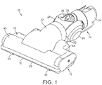
- a floor tool 10 comprises a cleaner head 12 rotatably attached to a coupling 14.
- the free end of the coupling 14 is attachable to a wand, hose or other such duct of a cleaning appliance (not shown).
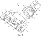
- the cleaner head 12 comprises a housing 16 and a lower plate, or sole plate 18, comprising a suction opening 20 through which a dirt-bearing fluid flow enters the cleaner head 12.
- the housing 16 defines a suction passage extending from the suction opening 20 to an outlet duct 22 located at the rear of the housing 16.
- the housing 16 preferably comprises a front bumper 23.
- the sole plate 18 comprises a plurality of support members 24 in the form of rolling elements mounted within recessed portions of the sole plate 18 for supporting the cleaner head 12 on a floor surface.
- the support members 24 are preferably arranged to support the sole plate 18 above the floor surface when the cleaner head 12 is located on a hard floor surface 66, and, when the cleaner head 12 is located on a carpeted floor surface 64, to sink into the pile of the carpet to enable the bottom surface of the sole plate 18 to engage the fibres of the carpet.
- the sole plate 18 is preferably pivotable relative to the housing 16 to allow the sole plate 18 to ride smoothly over the carpeted floor surface 64 during cleaning.
- the coupling 14 comprises a conduit 26 supported by a pair of wheels 28, 30.
- the conduit 26 comprises a forward portion 32 connected to the outlet duct 22, a rearward portion 34 pivotably connected to the forward portion 32 and connectable to a wand, hose or other such duct of a cleaning appliance which comprises dirt and dust separating apparatus and a motor-driven fan unit for drawing dirt-bearing air through the suction opening 20 from the floor surface.
- a flexible hose 36 is held within and extends between the forward and the rearward portions 32, 34 of the conduit 26.
- the cleaner head 12 comprises agitating apparatus for agitating dirt and dust located on the floor surface.
- the agitating apparatus comprises a rotatable brush bar 40 which is mounted within a brush bar chamber 42 of the housing 16.
- the brush bar chamber 42 is partially defined by a generally semi-cylindrical portion 43 of the housing 16, which is preferably formed from transparent material.
- the brush bar 40 is driven by a motor (not shown) located in a motor housing 44 of the housing 16.
- the motor is electrically connected to a terminal located in the rearward portion 34 of the conduit 26 for connection with a conformingly profiled terminal located in a duct of the cleaning appliance to enable electrical power to be supplied to the motor.
- the brush bar 40 is connected to the motor by a drive mechanism located, at least in part, within a drive mechanism housing 46 so that the drive mechanism is isolated from the air passing through the suction passage.
- One end of the brush bar 40 is connected to the drive mechanism to enable the brush bar 40 to be driven by the motor, whereas the other end of the brush bar 40 is rotatably supported by an end cap 48 mounted on a side wall of the brush bar chamber 42.
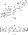
- the brush bar 40 is illustrated in more detail in Figures 4 to 6 .
- the brush bar 40 comprises an elongate body 50 bearing two different types of agitating means for agitating dirt and dust from the floor surface as the brush bar 40 is rotated by the motor.
- Each of the different types of agitating means protrudes from the suction opening 20 in the sole plate 18 as the brush bar 40 is rotated by the motor.
- a spindle 51 is mounted on one end of the body 50, with the spindle 51 being in turn connected to the end cap 48.
- a first agitating means mounted on the body 50 of the brush bar 40 comprises relatively short, preferably relatively stiff, bristles 52. These bristles 52 are preferably formed from nylon. In this embodiment the relatively short bristles 52 are arranged in two angularly spaced, helical rows extending along the body 50. Within each row, the relatively short bristles 52 are arranged in a series of clusters or tufts 53 regularly spaced along the row. Each tuft 53 preferably comprises around 100 to 150 bristles, with each tuft 53 having a diameter in the range from 2 to 4 mm. The diameter of each bristle 52 is preferably in the range from 100 to 200 ⁇ m. The length of the relatively short bristles 52 is chosen so that, when the floor tool 50 is assembled, the tips of these bristles 52 do not protrude beneath a plane extending between the lowermost extremities of the support members 24 during rotation of the brush bar 40.
- a second agitating means mounted on the body 50 of the brush bar 40 comprises relatively long, preferably relatively soft, bristles 54.
- the relatively long bristles 54 protrude radially outwardly from the body 50 beyond the relatively short bristles 52.
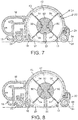
- the relatively short bristles 52 sweep a cylindrical volume having a diameter D1
- the relatively long bristles 54 sweep a cylindrical volume having a diameter D2 which is greater than D1.
- the difference between D1 and D2 is preferably in the range from 1 to 10 mm, more preferably in the range from 2 to 6 mm.
- the length of the relatively long bristles 54 is chosen so that the relatively long bristles 54 protrude beyond the plane extending between the lowermost extremities of the support members 24 during rotation of the brush bar 40.
- the relatively long bristles 54 are formed from material having a lower surface resistivity than the material from which the relatively short bristles 52 are formed.
- the surface resistivity of the relatively long bristles 54 is preferably in the range from 1x10 -5 to 1x10 12 ⁇ /sq.
- the surface resistivity of the relatively short bristles 52 is preferably higher than 1x10 12 ⁇ /sq.
- the relatively long bristles 54 may be formed from electrically conductive material.
- the bristles may be formed from metallic, graphite, conductive acrylic or other composite material, but in this example the relatively long bristles 54 comprise carbon fibre bristles.
- the diameter of each bristle 54 is preferably in the range from 5 to 20 ⁇ m.
- the body 50 comprises a plurality of angularly spaced, continuous rows of the relatively long bristles 54, which preferably also extend helically along the body 50.
- the body 50 comprises four continuous rows of the relatively long bristles 54, with each row being angularly spaced from a row of tufts 53 formed from the relatively short bristles 52.
- Each row of the relatively long bristles 54 preferably contains in the range from 20 to 100 bristles per mm length, and has a thickness in the range from 0.25 to 2 mm.
- adjacent rows of the relatively long bristles 54 are formed from a single strip 56 of bristles.
- Each strip 56 is preferably formed by attaching an elongate, generally rectangular flexible carrier member to a row of bristles so that each row of bristles 54 protrudes outwardly from a respective long side edge of the carrier member.
- the carrier member may be attached to the row of bristles by stitching or by using an adhesive.
- Each strip 56 is then located within a respective helical groove 58 formed in the body 50 so that the ends of the bristles protrude outwardly from the body 50.
- the strips 56 are connected to the body 50 by helical connectors 60 which are mounted on the strips 56 and connected to the body 50 using screws 62 into apertures formed in the connectors 60.
- the screws 62 may be pushed through the carrier member, or inserted through apertures formed in the carrier member.
- An adhesive tape may be applied to at least one side of each carrier member to allow the strips 56 to be aligned within the grooves 58 so that the ends of the bristles protrude from the body 50 by a regular amount along the length of the body 50.
- the sole plate 18 becomes spaced from the hard floor surface 66.
- the tips of the relatively short bristles 52 do not protrude beneath the plane extending between the lowermost extremities of the support members 24, these bristles do not come into contact with the hard floor surface 66, thereby preventing scratching or other marking of the hard floor surface 66 by these bristles.
- the relatively long bristles 54 protrude beyond this plane, these bristles engage, and are swept across, the hard floor surface 66 with rotation of the brush bar 40.
- any static electricity residing on the hard floor surface 66 is discharged upon contact with the relatively long bristles 54, thereby enabling fine dust and powder which would otherwise be attracted to the hard floor surface 66 to be dislodged from the floor surface by these bristles and entrained within the air flow.
- the cleaner head 12 includes a brush bar 40 that is driven by a motor.
- the cleaner head 12 may include alternative means for agitating or otherwise working a surface to be cleaned.
- the brush bar 40 may be driven by an air turbine rather than a motor.
- the relatively short bristles 52 may be formed from similar material as the relatively long bristles 54 in order to discharge any static material residing on a carpeted floor surface, and so may also have a surface resistivity in the range from 1x10 -5 to 1x10 12 ⁇ /sq.
- each strip 56 may be modified so that the bristles protrude from only one of the relatively long side edges of the carrier member.
- each strip 56 may be in the form of a brush, with bristles extending outwardly from only one side of the brush.
- a modified version of the brush bar 40', in which each strip 56 has been modified as discussed above, is illustrated in Figure 9 .
- This modification of the strips 56 results in the bristles 54 protruding outwardly from one side only of each connecting member 60. Consequently, this brush bar 40' contains only two continuous rows of relatively long bristles 54, with the rows of tufts 53 and the rows of relatively long bristles 54 being alternately arranged about the body 50 of the brush bar 40'.
- the relatively long bristles 54 protrude radially outwardly from the body 50 beyond the relatively short bristles 52.
- the different types of bristles 52, 54 need not be spaced apart.
- the brush bar 40 may comprise a plurality of rows, clumps or tufts of bristles, with each row, clump or tuft comprising both types of bristles.
- relatively short bristles 52 may be dispersed within each row of relatively long bristles 54.
- relatively long bristles 54 may be dispersed within each tuft 53 of relatively short bristles 52.
- the agitating means may take forms other than bristles, such as flexible or rigid strips of material mounted on the body 50, or filaments sewn into a backing material connected to the body 50.
- the relatively short bristles 52 may be dispensed with so that the brush bar 40 comprises only electrically conductive agitating members. Consequently, the brush bar 40 may comprise solely the continuous rows of surface agitating members defined by the relatively long bristles 54 illustrated in Figures 2 to 8 . Alternatively, the brush bar 40 may comprise a different arrangement of surface agitating members for discharging static electricity residing on a floor surface.
- a brush bar 80 for use in the floor tool 10 comprises a rotatable body 82 having an outer surface comprising an electrically conductive pile 84.
- the pile 84 is similar to the raised or fluffy surface of a carpet, rug or cloth, and comprises filaments woven on to a fabric carrier member 86 attached to the body 82, for example using an adhesive.
- the length of the filaments of the pile 84 is preferably in the range from 4 to 15 mm, and the filaments have a diameter which is preferably in the range from 5 to 20 ⁇ m.
- filaments are preferably formed from carbon fibres, but alternatively they may be formed from metallic material, conductive acrylic material or other composite material. Consequently, the surface resistivity of the filaments of the pile 84 is preferably in the range from 1x10 -5 to 1x10 12 ⁇ /sq.
- the fabric carrier member 86 may be in the form of a strip wound on to the body 82 so that the pile 84 is substantially continuous, substantially covering the outer surface of the body 82. Alternatively, the carrier member 86 may be in the form of a cylindrical sleeve into which the body 82 is inserted.
- clumps of relatively stiff bristles may be dispersed within the pile 84.
- a strip of the pile 84 may be wound around one or more helical rows of relatively stiff bristles previously attached to the body 82. These bristles may be similar to the relatively short bristles 52 of the brush bar 40, and so may be arranged so as to not protrude radially outwardly beyond the filaments of the pile 84.
Description
- The present invention relates to agitating apparatus for a surface treating appliance, and to a cleaner head for a surface treating appliance. In its preferred embodiment, the present invention relates to a cleaner head for a vacuum cleaning appliance.
- A vacuum cleaner typically comprises a main body containing dirt and dust separating apparatus, a cleaner head connected to the main body and having a suction opening, and a motor-driven fan unit for drawing dirt-bearing air through the suction opening. The dirt-bearing air is conveyed to the separating apparatus so that dirt and dust can be separated from the air before the air is expelled to the atmosphere.
- The suction opening is directed downwardly to face the floor surface to be cleaned. The separating apparatus can take the form of a filter, a filter bag or, as is known, a cyclonic arrangement. The present invention is not concerned with the nature of the separating apparatus and is therefore applicable to vacuum cleaners utilizing any of the above arrangements or another suitable separating apparatus.
- A driven agitator, usually in the form of a brush bar, is supported in the cleaner head so as to protrude to a small extent from the suction opening. The brush bar is activated mainly when the vacuum cleaner is used to clean carpeted surfaces. The brush bar comprises an elongate cylindrical core bearing bristles which extend radially outward from the core. The brush bar may be driven by an air turbine or by an electric motor powered by a power supply derived from the main body of the cleaner. The brush bar may be driven by the motor via a drive belt, or may be driven directly by the motor, so as to rotate within the suction opening. Rotation of the brush bar causes the bristles to sweep along the surface of the carpet to be cleaned to loosen dirt and dust, and pick up debris. The suction of air causes air to flow underneath the sole plate and around the brush bar to help lift the dirt and dust from the surface of the carpet and then carry it from the suction opening through the cleaner head towards the separating apparatus.
- The bristles of the brush bar are usually formed from nylon, and are usually arranged in tufts arranged about the core of the brush bar. While the use of nylon bristles provides an acceptable cleaning performance on carpeted floor surfaces, we have found that the use of nylon bristles generates static electricity when the floor tool is used on some hard floor surfaces, such as laminate, wood and vinyl surfaces, which attracts fine dust and powders, such as talcum powder, on to the floor surface. This can impair the cleaning performance on the cleaner head on such floor surfaces, as the sweeping action of the nylon bristles is insufficient to overcome the force attracting the fine dust to the floor surface.
- The bristle tufts have conventionally been mechanically secured to the brush bar core by individual staples. As a brush bar normally comprises at least forty bristle tufts, the use of staples can increase undesirably the cost of manufacture of the brush bar, particularly when it is desired to increase the number of bristle tufts to improve the agitating performance of the brush bar. It is therefore, desirable to provide an alternative, cheaper technique for attaching at least some of the agitating members, such as bristles, to a brush bar or other agitating apparatus.
-
WO 2006/080383 describes a cleaner head for a vacuum cleaner, which has a brush bar having a series of grooves. Bristles are mounted on carrier members which are inserted into the grooves.US 6,199,244 describes a cleaner head having a brush bar which has tufts of bristles which are electrically connected, and means for charging the tufts of bristles.GB 2,150,422 - In a first aspect, the present invention provides agitating apparatus for a surface treating appliance, comprising a rotatable body having a plurality of grooves formed therein, an agitating member located within each groove so that at least one side edge of the agitating member protrudes outwardly from the body, and a connecting member located within each groove for connecting the agitating member to the body, characterised in that the rotatable body comprises further surface agitating means having a surface resistivity which is different from the surface resistivity of the agitating members.
- The surface resistivity of the agitating members is preferably in the range from 1x10⁻⁵ to 1x10¹² Ω/sq (ohms per square). Values of surface resistivity discussed herein are as measured using the test method ASTM D257. The selection of material having a surface resistivity in this range can ensure that any static electricity on the floor surface is effectively discharged by the agitating members upon contact between the agitating members and the floor surface. This enables fine dust and powder which would otherwise be attracted to the floor surface to be dislodged from the floor surface by the agitating members.
- Each agitating member is preferably formed from one of metallic, carbon fibre, carbon composite, conductive acrylic, or other composite material. For example, material comprising carbon particles and carbon fibres generally has a surface resistivity in the range from 1x10³ to 1x10⁶ Ω/sq, whereas metallic material generally has a much lower surface resistivity, generally lower than 1 Ω/sq. Other static dissipative materials generally have a surface resistivity in the range from 1x10⁵ to 1x10¹² Ω/sq.
- Each agitating member is preferably flexible and is preferably in the form of a strip which may comprise a plurality of bristles, filaments or one or more strips of flexible material. Where the agitating members comprise at least one strip of material, each row is preferably formed from a single strip of material, or from a plurality of adjoining strips. Where the agitating members comprise a plurality of bristles or filaments, the bristles are arranged within each strip so that tips of the bristles are located along said at least one side edge. The bristles are preferably formed from carbon fibre or conductive acrylic fibres, such as Thunderon®. The bristles are preferably arranged in a closely packed formation so that each row of bristles is substantially continuous. For example, each strip preferably contains in the range from 20 to 100 bristles per mm length of the strip, and preferably has a thickness in the range from 0.25 to 2 mm. The diameter of each bristle is preferably in the range from 5 to 20 µm.
- The bristles may be connected, for example by stitching or using an adhesive, to an elongate carrier member so that individual or clumps of bristles do not come loose from the strip. For example, each agitating member may be in the form of a brush, with the bristles of each brush extending outwardly from the body, preferably so that the tips of the bristles are evenly spaced from the outer surface of the body.
- As mentioned above, the rotatable body has a plurality of grooves formed therein, and the apparatus comprises a plurality of connecting members, each of which is received within a respective groove to connect an agitating member to the body so that at least one side edge of the agitating member protrudes outwardly from the body. This can simplify manufacture of the agitating apparatus, and so reduce costs, as only one connecting member is required for, for example, a row of agitators extending along the brush bar. When the agitating members are formed from flexible material, the shape of the grooves defines the shape adopted by the portions of the agitating members which protrude outwardly from the body. For example, the grooves are preferably curved, more preferably at least partially helical, and so the agitating members adopt a shape which is at least partially helical when they are located within the grooves.
- Each agitating member is sandwiched between the body and a respective connecting member along its length. When the agitating members are formed from strips of bristles or filaments, this can prevent individual or clumps of bristles from being pulled out of the body. The connecting members preferably have substantially the same shape as the grooves, and preferably have an outer surface which is substantially flush with the outer surface of the body. For example, if the body is in the form of a cylinder then the outer surfaces of the connecting members preferably have substantially the same radius of curvature as the outer surface of the body. The connecting members may be connected to the body by one of a variety of different techniques, for example by using screws, interference fits or an adhesive.
- Each agitating member may be located within its respective groove so that only one of the side edges protrudes outwardly from the body, or so that both of the opposing side edges of the agitating member protrude outwardly from the body. This can enable, for example, the number of times that the agitating member engages a floor surface with each revolution of the body to be increased without having to increase the number of agitating members. In this latter case, the angle between the side edges of the agitating members, when connected to the body, is preferably less than 180°, and is preferably in the range from 45 to 135°.
- The rotatable body comprises further surface agitating means. The agitating apparatus thus comprises two different surface agitating means. The further surface agitating means are preferably located between the grooves of the body. Preferably, the agitating members protrude radially outwardly from the body beyond the further surface agitating mean, for example by a distance in the range from 0.5 to 5 mm, more preferably by a distance in the range from 1 to 3 mm.
- The relatively short, further surface agitating means may be configured to agitate dirt and dust from a carpeted floor surface, whereas the agitating members may be configured to sweep dirt and dust from a hard floor surface. The further surface agitating means is thus preferably relatively stiff in comparison to the agitating members. For example, bristles or filaments of the further surface agitating means may have a greater diameter than bristles or filaments of the agitating members. Alternatively, one or more strips of material forming the further surface agitating means may have a greater thickness than strips of material forming the agitating members.
- The further surface agitating means may be formed from electrically insulating, plastics material, such as nylon, and so may have a surface resistivity which is different to that of the agitating members. The surface resistivity of the further surface agitating means is preferably in the range from 1x10¹² to 1x10¹⁶ Ω/sq.
- The further surface agitating means is preferably arranged in a plurality of rows along the body, with these rows being preferably discontinuous. For example, where the further surface agitating means comprises a plurality of bristles these bristles are preferably arranged in one or more rows of clusters or tufts of bristles connected to and spaced along the body. However, the further surface agitating means may be located within, or otherwise in contact with, the agitating members. For example, each of the agitating means may comprises a plurality of bristles or filaments, with the bristles or filaments of the further surface agitating means being located adjacent, or amongst, bristles or filaments of the agitating members.
- The agitating apparatus is preferably in the form of a rotatable brush bar.
- In a second aspect, the present invention provides a cleaner head for a surface treating appliance, the cleaner head comprising a housing and apparatus as aforementioned. The cleaner head preferably comprises a sole plate having a suction opening through which dirt-bearing air enters the cleaner head, and through which the agitating members protrude as the body is rotated during use of the cleaner head, and a plurality of support members, preferably in the form of rolling elements, such as wheels or rollers, rotatably mounted on the sole plate, for supporting the cleaner head on a surface to be cleaned.
- In a third aspect, the present invention provides a surface treating appliance comprising a cleaner head or agitating apparatus as aforementioned.
- The term "surface treating appliance" is intended to have a broad meaning, and includes a wide range of machines having a main body and a head for travailing over a surface to clean or treat the surface in some manner. It includes, inter alia, machines which simply agitate the surface, such as carpet sweepers, machines which only apply suction to the surface, such as vacuum cleaners (dry, wet and wet/dry), so as to draw material from the surface, and machines which apply material to the surface, such as polishing/waxing machines, pressure washing machines and shampooing machines.
- Features described above in connection with the first aspect of the invention are equally applicable to any of the second to third aspects of the invention, and vice versa.
- An embodiment of the present invention will now be described, by way of example only, with reference to the accompanying drawings, in which:
-
Figure 1 is a front perspective view, from above of a floor tool; -
Figure 2 is a front perspective view, from below, of the floor tool ofFigure 1 ; -
Figure 3 is a bottom view of the floor tool ofFigure 1 ; -
Figure 4 is an exploded view of the brush bar of the floor tool ofFigure 1 ; -
Figure 5 is a perspective view of the brush bar ofFigure 4 ; -
Figure 6 is a top view of the brush bar ofFigure 4 ; -
Figure 7 is a section taken along line A-A illustrated inFigure 3 when the floor tool is located on a carpeted floor surface; -
Figure 8 is a section taken along line A-A illustrated inFigure 3 when the floor tool is located on a hard floor surface; -
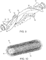
Figure 9 is a perspective view of a modified version of the brush bar ofFigure 4 ; and -
Figure 10 , which is not part of the present invention, is a perspective view of an alternative brush bar. - With reference first to
Figures 1 to 3 , afloor tool 10 comprises acleaner head 12 rotatably attached to acoupling 14. The free end of thecoupling 14 is attachable to a wand, hose or other such duct of a cleaning appliance (not shown). Thecleaner head 12 comprises ahousing 16 and a lower plate, orsole plate 18, comprising asuction opening 20 through which a dirt-bearing fluid flow enters thecleaner head 12. Thehousing 16 defines a suction passage extending from thesuction opening 20 to anoutlet duct 22 located at the rear of thehousing 16. Thehousing 16 preferably comprises afront bumper 23. Thesole plate 18 comprises a plurality ofsupport members 24 in the form of rolling elements mounted within recessed portions of thesole plate 18 for supporting thecleaner head 12 on a floor surface. With reference toFigures 7 and 8 , thesupport members 24 are preferably arranged to support thesole plate 18 above the floor surface when thecleaner head 12 is located on ahard floor surface 66, and, when thecleaner head 12 is located on acarpeted floor surface 64, to sink into the pile of the carpet to enable the bottom surface of thesole plate 18 to engage the fibres of the carpet. Thesole plate 18 is preferably pivotable relative to thehousing 16 to allow thesole plate 18 to ride smoothly over the carpetedfloor surface 64 during cleaning. - The
coupling 14 comprises aconduit 26 supported by a pair ofwheels conduit 26 comprises aforward portion 32 connected to theoutlet duct 22, arearward portion 34 pivotably connected to theforward portion 32 and connectable to a wand, hose or other such duct of a cleaning appliance which comprises dirt and dust separating apparatus and a motor-driven fan unit for drawing dirt-bearing air through the suction opening 20 from the floor surface. Aflexible hose 36 is held within and extends between the forward and therearward portions conduit 26. - The
cleaner head 12 comprises agitating apparatus for agitating dirt and dust located on the floor surface. In this example the agitating apparatus comprises arotatable brush bar 40 which is mounted within abrush bar chamber 42 of thehousing 16. Thebrush bar chamber 42 is partially defined by a generallysemi-cylindrical portion 43 of thehousing 16, which is preferably formed from transparent material. Thebrush bar 40 is driven by a motor (not shown) located in amotor housing 44 of thehousing 16. The motor is electrically connected to a terminal located in therearward portion 34 of theconduit 26 for connection with a conformingly profiled terminal located in a duct of the cleaning appliance to enable electrical power to be supplied to the motor. - The
brush bar 40 is connected to the motor by a drive mechanism located, at least in part, within adrive mechanism housing 46 so that the drive mechanism is isolated from the air passing through the suction passage. One end of thebrush bar 40 is connected to the drive mechanism to enable thebrush bar 40 to be driven by the motor, whereas the other end of thebrush bar 40 is rotatably supported by anend cap 48 mounted on a side wall of thebrush bar chamber 42. - The
brush bar 40 is illustrated in more detail inFigures 4 to 6 . Thebrush bar 40 comprises anelongate body 50 bearing two different types of agitating means for agitating dirt and dust from the floor surface as thebrush bar 40 is rotated by the motor. Each of the different types of agitating means protrudes from thesuction opening 20 in thesole plate 18 as thebrush bar 40 is rotated by the motor. Aspindle 51 is mounted on one end of thebody 50, with thespindle 51 being in turn connected to theend cap 48. - A first agitating means mounted on the
body 50 of thebrush bar 40 comprises relatively short, preferably relatively stiff, bristles 52. These bristles 52 are preferably formed from nylon. In this embodiment the relatively short bristles 52 are arranged in two angularly spaced, helical rows extending along thebody 50. Within each row, the relatively short bristles 52 are arranged in a series of clusters ortufts 53 regularly spaced along the row. Eachtuft 53 preferably comprises around 100 to 150 bristles, with eachtuft 53 having a diameter in the range from 2 to 4 mm. The diameter of each bristle 52 is preferably in the range from 100 to 200 µm. The length of the relatively short bristles 52 is chosen so that, when thefloor tool 50 is assembled, the tips of thesebristles 52 do not protrude beneath a plane extending between the lowermost extremities of thesupport members 24 during rotation of thebrush bar 40. - A second agitating means mounted on the
body 50 of thebrush bar 40 comprises relatively long, preferably relatively soft, bristles 54. As illustrated inFigure 7 , the relatively long bristles 54 protrude radially outwardly from thebody 50 beyond the relatively short bristles 52. During rotation of thebody 50, the relatively short bristles 52 sweep a cylindrical volume having a diameter D1, whereas the relatively long bristles 54 sweep a cylindrical volume having a diameter D2 which is greater than D1. The difference between D1 and D2 is preferably in the range from 1 to 10 mm, more preferably in the range from 2 to 6 mm. In contrast to the relatively short bristles 52, the length of the relatively long bristles 54 is chosen so that the relatively long bristles 54 protrude beyond the plane extending between the lowermost extremities of thesupport members 24 during rotation of thebrush bar 40. - The relatively long bristles 54 are formed from material having a lower surface resistivity than the material from which the relatively short bristles 52 are formed. The surface resistivity of the relatively long bristles 54 is preferably in the range from 1x10⁻⁵ to 1x10¹² Ω/sq. In comparison, the surface resistivity of the relatively short bristles 52 is preferably higher than 1x10¹² Ω/sq. The relatively long bristles 54 may be formed from electrically conductive material. The bristles may be formed from metallic, graphite, conductive acrylic or other composite material, but in this example the relatively long bristles 54 comprise carbon fibre bristles. The diameter of each bristle 54 is preferably in the range from 5 to 20 µm.
- The
body 50 comprises a plurality of angularly spaced, continuous rows of the relatively long bristles 54, which preferably also extend helically along thebody 50. In this embodiment thebody 50 comprises four continuous rows of the relatively long bristles 54, with each row being angularly spaced from a row oftufts 53 formed from the relatively short bristles 52. Each row of the relatively long bristles 54 preferably contains in the range from 20 to 100 bristles per mm length, and has a thickness in the range from 0.25 to 2 mm. - With particular reference to
Figure 4 , in this embodiment adjacent rows of the relatively long bristles 54 are formed from asingle strip 56 of bristles. Eachstrip 56 is preferably formed by attaching an elongate, generally rectangular flexible carrier member to a row of bristles so that each row ofbristles 54 protrudes outwardly from a respective long side edge of the carrier member. The carrier member may be attached to the row of bristles by stitching or by using an adhesive. Eachstrip 56 is then located within a respectivehelical groove 58 formed in thebody 50 so that the ends of the bristles protrude outwardly from thebody 50. Thestrips 56 are connected to thebody 50 byhelical connectors 60 which are mounted on thestrips 56 and connected to thebody 50 usingscrews 62 into apertures formed in theconnectors 60. Thescrews 62 may be pushed through the carrier member, or inserted through apertures formed in the carrier member. An adhesive tape may be applied to at least one side of each carrier member to allow thestrips 56 to be aligned within thegrooves 58 so that the ends of the bristles protrude from thebody 50 by a regular amount along the length of thebody 50. - With reference to
Figure 7 , when thecleaner head 12 is located on acarpeted floor surface 64 thesupport members 24 sink into the pile of the carpet so that the bottom surface of thesole plate 18 engages the fibres of the carpet. As both the relatively short bristles 52 and the relatively long bristles 54 protrude from thesuction opening 20 as thebrush bar 40 rotates, both the different types of bristles are able to agitate dirt and dust from the floor surface. When an air flow is generated through the suction passage of thecleaner head 12, this dirt and dust becomes entrained within the air flow and is conveyed through thefloor tool 10 to the cleaning appliance. - When the
cleaner head 12 is moved from the carpetedfloor surface 64 on to ahard floor surface 66, as illustrated inFigure 8 , thesole plate 18 becomes spaced from thehard floor surface 66. As the tips of the relatively short bristles 52 do not protrude beneath the plane extending between the lowermost extremities of thesupport members 24, these bristles do not come into contact with thehard floor surface 66, thereby preventing scratching or other marking of thehard floor surface 66 by these bristles. However, as the relatively long bristles 54 protrude beyond this plane, these bristles engage, and are swept across, the hard floor surface 66 with rotation of thebrush bar 40. Due to the relatively low surface resistivity of the relatively long bristles 54, any static electricity residing on thehard floor surface 66 is discharged upon contact with the relatively long bristles 54, thereby enabling fine dust and powder which would otherwise be attracted to the hard floor surface 66 to be dislodged from the floor surface by these bristles and entrained within the air flow. - The invention is not limited to the detailed description given above. Variations will be apparent to the person skilled in the art.
- For example, in the embodiment described above, the
cleaner head 12 includes abrush bar 40 that is driven by a motor. However, thecleaner head 12 may include alternative means for agitating or otherwise working a surface to be cleaned. By way of example, thebrush bar 40 may be driven by an air turbine rather than a motor. - The relatively short bristles 52 may be formed from similar material as the relatively long bristles 54 in order to discharge any static material residing on a carpeted floor surface, and so may also have a surface resistivity in the range from 1x10⁻⁵ to 1x10¹² Ω/sq.
- Each
strip 56 may be modified so that the bristles protrude from only one of the relatively long side edges of the carrier member. Thus, eachstrip 56 may be in the form of a brush, with bristles extending outwardly from only one side of the brush. A modified version of the brush bar 40', in which eachstrip 56 has been modified as discussed above, is illustrated inFigure 9 . This modification of thestrips 56 results in thebristles 54 protruding outwardly from one side only of each connectingmember 60. Consequently, this brush bar 40' contains only two continuous rows of relatively long bristles 54, with the rows oftufts 53 and the rows of relatively long bristles 54 being alternately arranged about thebody 50 of the brush bar 40'. As with thebrush bar 40, the relatively long bristles 54 protrude radially outwardly from thebody 50 beyond the relatively short bristles 52. - The different types of
bristles brush bar 40 may comprise a plurality of rows, clumps or tufts of bristles, with each row, clump or tuft comprising both types of bristles. For example, relatively short bristles 52 may be dispersed within each row of relatively long bristles 54. Alternatively, relatively long bristles 54 may be dispersed within eachtuft 53 of relatively short bristles 52. - The agitating means may take forms other than bristles, such as flexible or rigid strips of material mounted on the
body 50, or filaments sewn into a backing material connected to thebody 50. - In the event that the
floor tool 10 is not to be used on a carpeted surface, the relatively short bristles 52 may be dispensed with so that thebrush bar 40 comprises only electrically conductive agitating members. Consequently, thebrush bar 40 may comprise solely the continuous rows of surface agitating members defined by the relatively long bristles 54 illustrated inFigures 2 to 8 . Alternatively, thebrush bar 40 may comprise a different arrangement of surface agitating members for discharging static electricity residing on a floor surface. - For example, with reference to
Figure 10 , which is not part of the present invention, abrush bar 80 for use in thefloor tool 10 comprises arotatable body 82 having an outer surface comprising an electricallyconductive pile 84. In this example, thepile 84 is similar to the raised or fluffy surface of a carpet, rug or cloth, and comprises filaments woven on to a fabric carrier member 86 attached to thebody 82, for example using an adhesive. The length of the filaments of thepile 84 is preferably in the range from 4 to 15 mm, and the filaments have a diameter which is preferably in the range from 5 to 20 µm. - These filaments are preferably formed from carbon fibres, but alternatively they may be formed from metallic material, conductive acrylic material or other composite material. Consequently, the surface resistivity of the filaments of the
pile 84 is preferably in the range from 1x10⁻⁵ to 1x10¹² Ω/sq. The fabric carrier member 86 may be in the form of a strip wound on to thebody 82 so that thepile 84 is substantially continuous, substantially covering the outer surface of thebody 82. Alternatively, the carrier member 86 may be in the form of a cylindrical sleeve into which thebody 82 is inserted. - If so desired, clumps of relatively stiff bristles may be dispersed within the
pile 84. Alternatively, a strip of thepile 84 may be wound around one or more helical rows of relatively stiff bristles previously attached to thebody 82. These bristles may be similar to the relatively short bristles 52 of thebrush bar 40, and so may be arranged so as to not protrude radially outwardly beyond the filaments of thepile 84.
Claims (17)
- Agitating apparatus for a surface treating appliance, comprising a rotatable body (50) having a plurality of grooves (58) formed therein, an agitating member (56) located within each groove (58) so that at least one side edge of the agitating member (56) protrudes outwardly from the body (50), and a connecting member (60) located within each groove (58) for connecting the agitating member (56) to the body (50), the rotatable body (50) comprising further surface agitating means (52) having a surface resistivity which is different from the surface resistivity of the agitating members (56), characterised in that each agitating member (56) is sandwiched between the body (50) and a respective connecting member (60) along the length thereof.
- Apparatus as claimed in claim 1, wherein the surface resistivity of each agitating member (56) is in the range from 1x10⁻⁵ to 1x10¹² Ω/sq.
- Apparatus as claimed in claim 1 or claim 2, wherein each agitating member (56) is formed from one of metallic, carbon fibre, conductive acrylic and composite material.
- Apparatus as claimed in any of the preceding claims, wherein each groove (58) is at least partially helical.
- Apparatus as claimed in any of the preceding claims, wherein the outer surface of the connecting member (60) is substantially flush with the outer surface of the body (50).
- Apparatus as claimed in any of the preceding claims, wherein each agitating member (56) is located within its respective groove (58) so that opposing side edges of the agitating member (56) protrude outwardly from the body (50).
- Apparatus as claimed in any of the preceding claims, wherein each agitating member (56) is flexible.
- Apparatus as claimed in any of the preceding claims, wherein each agitating member (56) is in the form of a strip.
- Apparatus as claimed in claim 8, wherein each strip (56) is formed from a plurality of bristles (54).
- Apparatus as claimed in claim 9, wherein each strip (56) contains in the range from 20 to 100 bristles per mm length of the strip.
- Apparatus as claimed in claim 9 or claim 10, wherein the bristles (54) have a diameter in the range from 5 to 20 µm.
- Apparatus as claimed in any of claims 8 to 11, wherein each strip (56) has a thickness in the range from 0.25 to 2 mm.
- Apparatus as claimed in any preceding claim, wherein the further surface agitating means (52) are located between the grooves (58) of the body (50).
- Apparatus as claimed in any preceding claim, wherein the further surface agitating means (52) is arranged in a plurality of rows along the body (50).
- Apparatus as claimed in claim 14, wherein the rows of further surface agitating means (52) are discontinuous.
- Apparatus as claimed in any preceding claim, wherein the stiffness of the further surface agitating means (52) is different from the stiffness of the agitating members (56).
- Apparatus as claimed in any preceding claim, wherein the further surface agitating means (52) comprises one of a plurality of bristles, a plurality of filaments, and at least one strip of material.
Applications Claiming Priority (2)
| Application Number | Priority Date | Filing Date | Title |
|---|---|---|---|
| GB0909898A GB2470919A (en) | 2009-06-09 | 2009-06-09 | Agitating means for a cleaning head |
| PCT/GB2010/050853 WO2010142970A1 (en) | 2009-06-09 | 2010-05-25 | A cleaner head |
Publications (3)
| Publication Number | Publication Date |
|---|---|
| EP2440099A1 EP2440099A1 (en) | 2012-04-18 |
| EP2440099B1 EP2440099B1 (en) | 2016-04-27 |
| EP2440099B2 true EP2440099B2 (en) | 2019-09-11 |
Family
ID=40937113
Family Applications (1)
| Application Number | Title | Priority Date | Filing Date |
|---|---|---|---|
| EP10722178.0A Active EP2440099B2 (en) | 2009-06-09 | 2010-05-25 | A cleaner head |
Country Status (8)
| Country | Link |
|---|---|
| US (1) | US8316503B2 (en) |
| EP (1) | EP2440099B2 (en) |
| JP (1) | JP5465611B2 (en) |
| KR (1) | KR101358773B1 (en) |
| CN (1) | CN101919670B (en) |
| AU (1) | AU2010258413B2 (en) |
| GB (1) | GB2470919A (en) |
| WO (1) | WO2010142970A1 (en) |
Families Citing this family (65)
| Publication number | Priority date | Publication date | Assignee | Title |
|---|---|---|---|---|
| CA2599303A1 (en) | 2007-08-29 | 2009-02-28 | Gbd Corp. | Surface cleaning apparatus |
| US20210401246A1 (en) | 2016-04-11 | 2021-12-30 | Omachron Intellectual Property Inc. | Surface cleaning apparatus |
| US10165912B2 (en) | 2006-12-15 | 2019-01-01 | Omachron Intellectual Property Inc. | Surface cleaning apparatus |
| US9192269B2 (en) | 2006-12-15 | 2015-11-24 | Omachron Intellectual Property Inc. | Surface cleaning apparatus |
| US11857142B2 (en) | 2006-12-15 | 2024-01-02 | Omachron Intellectual Property Inc. | Surface cleaning apparatus having an energy storage member and a charger for an energy storage member |
| US9888817B2 (en) | 2014-12-17 | 2018-02-13 | Omachron Intellectual Property Inc. | Surface cleaning apparatus |
| US9265395B2 (en) | 2010-03-12 | 2016-02-23 | Omachron Intellectual Property Inc. | Surface cleaning apparatus |
| US10722086B2 (en) | 2017-07-06 | 2020-07-28 | Omachron Intellectual Property Inc. | Handheld surface cleaning apparatus |
| US9433332B2 (en) | 2013-02-27 | 2016-09-06 | Omachron Intellectual Property Inc. | Surface cleaning apparatus |
| GB2470917A (en) * | 2009-06-09 | 2010-12-15 | Dyson Technology Ltd | Agitating means for cleaning head |
| GB2470920A (en) * | 2009-06-09 | 2010-12-15 | Dyson Technology Ltd | Agitating menas for a cleaning head |
| GB2470918A (en) * | 2009-06-09 | 2010-12-15 | Dyson Technology Ltd | Agitating means for a cleaning head |
| GB2476810B (en) | 2010-01-08 | 2014-01-08 | Dyson Technology Ltd | Cleaner head for a vacuum cleaner |
| US11471020B2 (en) | 2011-04-29 | 2022-10-18 | Irobot Corporation | Robotic vacuum cleaning system |
| US9220386B2 (en) | 2011-04-29 | 2015-12-29 | Irobot Corporation | Robotic vacuum |
| US8904595B2 (en) | 2011-12-13 | 2014-12-09 | Electrolux Home Care Products, Inc. | Vacuum cleaner floor seal |
| US9320401B2 (en) | 2013-02-27 | 2016-04-26 | Omachron Intellectual Property Inc. | Surface cleaning apparatus |
| US9591958B2 (en) | 2013-02-27 | 2017-03-14 | Omachron Intellectual Property Inc. | Surface cleaning apparatus |
| US9027198B2 (en) | 2013-02-27 | 2015-05-12 | G.B.D. Corp. | Surface cleaning apparatus |
| US9326654B2 (en) | 2013-03-15 | 2016-05-03 | Irobot Corporation | Roller brush for surface cleaning robots |
| GB201313707D0 (en) | 2013-07-31 | 2013-09-11 | Dyson Technology Ltd | Cleaner head for a vacuum cleaner |
| KR101556177B1 (en) | 2014-05-07 | 2015-09-30 | 엘지전자 주식회사 | Vacuum cleaner |
| US9420925B2 (en) | 2014-07-18 | 2016-08-23 | Omachron Intellectual Property Inc. | Portable surface cleaning apparatus |
| US9585530B2 (en) | 2014-07-18 | 2017-03-07 | Omachron Intellectual Property Inc. | Portable surface cleaning apparatus |
| US9314139B2 (en) | 2014-07-18 | 2016-04-19 | Omachron Intellectual Property Inc. | Portable surface cleaning apparatus |
| US9451853B2 (en) | 2014-07-18 | 2016-09-27 | Omachron Intellectual Property Inc. | Portable surface cleaning apparatus |
| US10251519B2 (en) | 2014-12-17 | 2019-04-09 | Omachron Intellectual Property Inc. | Surface cleaning apparatus |
| US11950745B2 (en) | 2014-12-17 | 2024-04-09 | Omachron Intellectual Property Inc. | Surface cleaning apparatus |
| US10136778B2 (en) | 2014-12-17 | 2018-11-27 | Omachron Intellectual Property Inc. | Surface cleaning apparatus |
| US11607095B2 (en) * | 2015-01-30 | 2023-03-21 | Sharkninja Operating Llc | Removable rotatable driven agitator for surface cleaning head |
| US9456723B2 (en) | 2015-01-30 | 2016-10-04 | Sharkninja Operating Llc | Surface cleaning head including openable agitator chamber and a removable rotatable agitator |
| US9955832B2 (en) | 2015-01-30 | 2018-05-01 | Sharkninja Operating Llc | Surface cleaning head with removable non-driven agitator having cleaning pad |
| US9655486B2 (en) | 2015-01-30 | 2017-05-23 | Sharkninja Operating Llc | Surface cleaning head including removable rotatable driven agitator |
| USD781013S1 (en) | 2015-05-18 | 2017-03-07 | Sharkninja Operating Llc | Vacuum cleaner head cover |
| USD789006S1 (en) | 2015-05-15 | 2017-06-06 | Sharkninja Operating Llc | Vacuum cleaner |
| US10076183B2 (en) | 2015-08-14 | 2018-09-18 | Sharkninja Operating Llc | Surface cleaning head |
| US10702108B2 (en) | 2015-09-28 | 2020-07-07 | Sharkninja Operating Llc | Surface cleaning head for vacuum cleaner |
| KR102115326B1 (en) | 2015-10-21 | 2020-05-27 | 샤크닌자 오퍼레이팅 엘엘씨 | Surface cleaning head |
| US11647881B2 (en) | 2015-10-21 | 2023-05-16 | Sharkninja Operating Llc | Cleaning apparatus with combing unit for removing debris from cleaning roller |
| USD837469S1 (en) | 2016-07-22 | 2019-01-01 | Sharkninja Operating Llc | Vacuum cleaner |
| US10512384B2 (en) | 2016-12-15 | 2019-12-24 | Irobot Corporation | Cleaning roller for cleaning robots |
| US10925454B2 (en) * | 2017-04-20 | 2021-02-23 | Lg Electronics Inc. | Vacuum cleaner |
| US11202542B2 (en) | 2017-05-25 | 2021-12-21 | Sharkninja Operating Llc | Robotic cleaner with dual cleaning rollers |
| CN110708993A (en) | 2017-06-06 | 2020-01-17 | 阿尔弗雷德·卡赫欧洲两合公司 | Floor nozzle device, cleaning roller for cleaning a textile surface and suction machine |
| US10842330B2 (en) | 2017-07-06 | 2020-11-24 | Omachron Intellectual Property Inc. | Handheld surface cleaning apparatus |
| US10750913B2 (en) | 2017-07-06 | 2020-08-25 | Omachron Intellectual Property Inc. | Handheld surface cleaning apparatus |
| US11730327B2 (en) | 2020-03-18 | 2023-08-22 | Omachron Intellectual Property Inc. | Surface cleaning apparatus with removable air treatment assembly |
| US10537216B2 (en) | 2017-07-06 | 2020-01-21 | Omachron Intellectual Property Inc. | Handheld surface cleaning apparatus |
| US10631693B2 (en) | 2017-07-06 | 2020-04-28 | Omachron Intellectual Property Inc. | Handheld surface cleaning apparatus |
| US11766156B2 (en) | 2020-03-18 | 2023-09-26 | Omachron Intellectual Property Inc. | Surface cleaning apparatus with removable air treatment member assembly |
| US11666193B2 (en) | 2020-03-18 | 2023-06-06 | Omachron Intellectual Property Inc. | Surface cleaning apparatus with removable air treatment member assembly |
| US10506904B2 (en) | 2017-07-06 | 2019-12-17 | Omachron Intellectual Property Inc. | Handheld surface cleaning apparatus |
| US10702113B2 (en) | 2017-07-06 | 2020-07-07 | Omachron Intellectual Property Inc. | Handheld surface cleaning apparatus |
| US11445878B2 (en) | 2020-03-18 | 2022-09-20 | Omachron Intellectual Property Inc. | Surface cleaning apparatus with removable air treatment member assembly |
| US10595624B2 (en) | 2017-07-25 | 2020-03-24 | Irobot Corporation | Cleaning roller for cleaning robots |
| US10517455B2 (en) * | 2017-10-26 | 2019-12-31 | Irobot Corporation | Electrostatic discharge systems for autonomous mobile robots |
| EP3517014B1 (en) * | 2018-01-25 | 2021-01-06 | Carl Freudenberg KG | Rotatable cleaning roller and sweeping device with such a roller |
| US11006799B2 (en) | 2018-08-13 | 2021-05-18 | Omachron Intellectual Property Inc. | Cyclonic air treatment member and surface cleaning apparatus including the same |
| US11192122B2 (en) | 2018-08-13 | 2021-12-07 | Omachron Intellectual Property Inc. | Cyclonic air treatment member and surface cleaning apparatus including the same |
| US11013384B2 (en) | 2018-08-13 | 2021-05-25 | Omachron Intellectual Property Inc. | Cyclonic air treatment member and surface cleaning apparatus including the same |
| US11291345B2 (en) | 2018-08-27 | 2022-04-05 | Techtronic Floor Care Technology Limited | Floor cleaner |
| KR20230051612A (en) | 2018-10-19 | 2023-04-18 | 샤크닌자 오퍼레이팅 엘엘씨 | Agitator for a surface treatment apparatus and a surface treatment apparatus having the same |
| US11109727B2 (en) | 2019-02-28 | 2021-09-07 | Irobot Corporation | Cleaning rollers for cleaning robots |
| GB2606154B (en) * | 2021-04-26 | 2023-12-27 | Dyson Technology Ltd | Brushbar for a vacuum cleaner |
| KR20230041377A (en) * | 2021-09-17 | 2023-03-24 | 삼성전자주식회사 | Drum module for cleaner and cleaner including same |
Citations (2)
| Publication number | Priority date | Publication date | Assignee | Title |
|---|---|---|---|---|
| GB1360309A (en) † | 1971-03-29 | 1974-07-17 | Nat Union Electric Corp | Brush roll assemblies in or for cleaning devices |
| JPH0610577A (en) † | 1992-06-25 | 1994-01-18 | Yoshikazu Yamamoto | Retractable shutter |
Family Cites Families (62)
| Publication number | Priority date | Publication date | Assignee | Title |
|---|---|---|---|---|
| US2281863A (en) * | 1939-07-10 | 1942-05-05 | Hoover Co | Suction cleaner |
| US2426315A (en) | 1943-09-25 | 1947-08-26 | Us Rubber Co | Static free brush |
| US2459007A (en) | 1945-04-09 | 1949-01-11 | Westinghouse Electric Corp | Brush roll for suction cleaners |
| US2659921A (en) | 1947-11-01 | 1953-11-24 | Eureka Williams Corp | Rotary brush for suction cleaners |
| US2578549A (en) * | 1948-07-26 | 1951-12-11 | Robert O Hooban | Power-driven clothes-cleaning brush |
| GB734360A (en) | 1951-12-10 | 1955-07-27 | Wessel Hans | Vacuum cleaning device for cattle, horses and other animals |
| US3186019A (en) | 1961-05-19 | 1965-06-01 | Hattori Ryosuke | Circular brush |
| US3614801A (en) * | 1970-04-22 | 1971-10-26 | Tennant Co | Rotary tubular brush |
| US3815170A (en) | 1972-06-30 | 1974-06-11 | Nat Union Electric Corp | Cleaning nozzle attachment for a suction cleaner |
| JPS5523469Y2 (en) * | 1975-06-20 | 1980-06-04 | ||
| US4186030A (en) | 1976-11-04 | 1980-01-29 | Armstrong John L | Carpet cleaning |
| US4197610A (en) | 1977-10-17 | 1980-04-15 | California Institute Of Technology | Cleaning devices |
| GB2150422B (en) * | 1980-11-28 | 1985-12-04 | Hoover Ltd | Suction cleaner agitators |
| GB2090124B (en) | 1980-12-30 | 1984-07-18 | Livingstone Simon Howard | Method and apparatus for cleaning carpets |
| DE3205199A1 (en) * | 1982-02-13 | 1983-08-25 | Düpro AG, 8590 Romanshorn | Roller-type brush for a cleaning device and a method of manufacturing such a brush |
| US4435073A (en) | 1982-08-16 | 1984-03-06 | Xerox Corporation | Toner removal apparatus |
| GB2135869A (en) | 1982-12-10 | 1984-09-12 | Hukuba Kogyo Kk | Rotary cleaning member |
| DE3418224A1 (en) | 1983-05-16 | 1984-11-22 | Dresser Industries, Inc., Dallas, Tex. | Antistatic brush and method of manufacturing the latter |
| US4706320A (en) * | 1985-12-04 | 1987-11-17 | Xerox Corporation | Electrostatic charging and cleaning brushes |
| DE3879867T2 (en) * | 1987-10-23 | 1993-10-14 | Matsushita Electric Ind Co Ltd | Vacuum cleaner mouthpiece. |
| US4835807A (en) | 1988-01-28 | 1989-06-06 | Xerox Corporation | Cleaning brush |
| US5150499A (en) | 1990-11-16 | 1992-09-29 | Shop Vac Corporation | Static electric discharge for dust collector |
| US5187526A (en) | 1991-09-23 | 1993-02-16 | Eastman Kodak Company | Method and apparatus of forming a toner image on a receiving sheet using an intermediate image member |
| JPH05317226A (en) * | 1991-12-02 | 1993-12-03 | Hookii:Kk | Rotary brush |
| JP3198150B2 (en) | 1992-03-26 | 2001-08-13 | 株式会社国盛化学 | Method of manufacturing rotary brush in vacuum cleaner |
| JPH06105771A (en) | 1992-09-25 | 1994-04-19 | Hitachi Ltd | Suction mouth of vacuum cleaner |
| DE4306734A1 (en) | 1993-03-04 | 1994-09-08 | Heidelberger Druckmasch Ag | Brush in rotary printing machines |
| JP3295744B2 (en) * | 1993-06-14 | 2002-06-24 | 株式会社コーワ | Suction nozzle for vacuum cleaner |
| JP3256791B2 (en) * | 1993-06-28 | 2002-02-12 | 株式会社コーワ | Suction nozzle for vacuum cleaner |
| US5452490A (en) * | 1993-07-02 | 1995-09-26 | Royal Appliance Mfg. Co. | Brushroll with dual row of bristles |
| JP3446307B2 (en) | 1994-06-06 | 2003-09-16 | 松下電器産業株式会社 | Floor nozzle rotating brush |
| DE19522981A1 (en) | 1995-06-28 | 1997-01-02 | Fedag Romanshorn Fa | Electric vacuum cleaner suction tool |
| DE19547311A1 (en) | 1995-12-18 | 1997-06-19 | Wessel Werk Gmbh | Vacuum cleaner nozzle discharges carpet or floor |
| US5689791A (en) | 1996-07-01 | 1997-11-18 | Xerox Corporation | Electrically conductive fibers |
| GB9725777D0 (en) | 1997-12-04 | 1998-02-04 | Notetry Ltd | A cleaner head and brush bar therefor |
| JPH11216088A (en) | 1998-02-02 | 1999-08-10 | Sharp Corp | Vacuum cleaner suction body and manufacture of rotary cleaning member of the same |
| US5905932A (en) | 1998-04-04 | 1999-05-18 | Eastman Kodak Company | Method and apparatus for the removal of toner and magnetic carrier particles from a surface |
| JP4099872B2 (en) | 1998-08-26 | 2008-06-11 | 松下電器産業株式会社 | Vacuum cleaner suction tool and vacuum cleaner |
| DE19846103A1 (en) | 1998-10-07 | 2000-04-20 | Vorwerk Co Interholding | vacuum cleaner |
| JP2000217753A (en) * | 1999-02-02 | 2000-08-08 | Sharp Corp | Sucking port body for electric vacuum cleaner |
| US6267660B1 (en) | 1999-02-02 | 2001-07-31 | Poul Erik Jespersen | Rotatable grinding or polishing tool, an apparatus with such a tool and a method for grinding or polishing |
| US6539575B1 (en) * | 1999-07-02 | 2003-04-01 | Oreck Holdings, Llc | Agitator for a cleaning machine with material cutting channel |
| JP2002136457A (en) * | 2000-10-31 | 2002-05-14 | Matsushita Electric Ind Co Ltd | Vacuum cleaner of exhaust circulation type |
| JP2003052584A (en) | 2001-08-10 | 2003-02-25 | Tsuchiya Tsco Co Ltd | Rotating brush for vacuum cleaner |
| JP4226272B2 (en) * | 2002-05-22 | 2009-02-18 | 日立アプライアンス株式会社 | Vacuum cleaner and its mouthpiece |
| WO2004047605A1 (en) * | 2002-11-22 | 2004-06-10 | Toshiba Tec Kabushiki Kaisha | Rotary cleaning-body, and method of producing suction inlet body and the rotary cleaning-body |
| JP2004267452A (en) | 2003-03-07 | 2004-09-30 | Sharp Corp | Dust collecting container and vacuum cleaner provided therewith |
| US20050039282A1 (en) | 2003-08-22 | 2005-02-24 | Oreck Holdings, Llc | Vacuum cleaner brushroll |
| JP2005066034A (en) | 2003-08-25 | 2005-03-17 | Toshiba Tec Corp | Rotating cleaning body and suction port body of vacuum cleaner |
| JP2005168796A (en) | 2003-12-11 | 2005-06-30 | Matsushita Electric Ind Co Ltd | Floor nozzle for vacuum cleaner |
| US7081043B2 (en) | 2004-01-14 | 2006-07-25 | 3M Innovative Properties Company | Molded abrasive brush and methods of using for manufacture of printed circuit boards |
| JP4563706B2 (en) | 2004-02-23 | 2010-10-13 | 株式会社コーワ | Rotating rotor of floor nozzle for vacuum cleaner |
| GB2422093B (en) | 2005-01-18 | 2008-04-09 | Dyson Technology Ltd | Cleaner head for a cleaning appliance |
| WO2006080383A1 (en) | 2005-01-31 | 2006-08-03 | Toshiba Tec Kabushiki Kaisha | Electric cleaner and suction mouth body |
| AU2006223465A1 (en) | 2005-03-11 | 2006-09-21 | Tennant Company | Hard and soft floor cleaning tool and machine |
| AU2006201894B2 (en) | 2005-05-05 | 2010-09-16 | Bissell Inc. | Vacuum accessory tool |
| JP2007313037A (en) * | 2006-05-26 | 2007-12-06 | Kowa Co Ltd | Washing brush for car washer and car washer |
| WO2008098855A1 (en) * | 2007-02-16 | 2008-08-21 | BSH Bosch und Siemens Hausgeräte GmbH | Brush head of a cleaning device and cleaning device having such a brush head |
| CN102046060A (en) | 2008-06-10 | 2011-05-04 | 阿尔弗雷德·凯驰两合公司 | Cleaning roller for a floor cleaning machine |
| GB2470920A (en) | 2009-06-09 | 2010-12-15 | Dyson Technology Ltd | Agitating menas for a cleaning head |
| GB2470917A (en) | 2009-06-09 | 2010-12-15 | Dyson Technology Ltd | Agitating means for cleaning head |
| GB2470918A (en) | 2009-06-09 | 2010-12-15 | Dyson Technology Ltd | Agitating means for a cleaning head |
-
2009
- 2009-06-09 GB GB0909898A patent/GB2470919A/en not_active Withdrawn
-
2010
- 2010-05-25 EP EP10722178.0A patent/EP2440099B2/en active Active
- 2010-05-25 WO PCT/GB2010/050853 patent/WO2010142970A1/en active Application Filing
- 2010-05-25 KR KR1020117030039A patent/KR101358773B1/en active IP Right Grant
- 2010-05-25 AU AU2010258413A patent/AU2010258413B2/en not_active Ceased
- 2010-06-01 US US12/791,640 patent/US8316503B2/en active Active
- 2010-06-09 JP JP2010132237A patent/JP5465611B2/en active Active
- 2010-06-09 CN CN201010201083.2A patent/CN101919670B/en active Active
Patent Citations (2)
| Publication number | Priority date | Publication date | Assignee | Title |
|---|---|---|---|---|
| GB1360309A (en) † | 1971-03-29 | 1974-07-17 | Nat Union Electric Corp | Brush roll assemblies in or for cleaning devices |
| JPH0610577A (en) † | 1992-06-25 | 1994-01-18 | Yoshikazu Yamamoto | Retractable shutter |
Non-Patent Citations (1)
| Title |
|---|
| PATRICK S.G.: "Practical Guide to Polyvinyl Chloride", 2005, RAPRA TECHNOLOGY LIMITED, Shawbury, UK, ISBN: 1-85957-511-01 † |
Also Published As
| Publication number | Publication date |
|---|---|
| JP2010284528A (en) | 2010-12-24 |
| US8316503B2 (en) | 2012-11-27 |
| EP2440099A1 (en) | 2012-04-18 |
| US20100306956A1 (en) | 2010-12-09 |
| EP2440099B1 (en) | 2016-04-27 |
| JP5465611B2 (en) | 2014-04-09 |
| GB2470919A (en) | 2010-12-15 |
| KR101358773B1 (en) | 2014-02-06 |
| KR20120025525A (en) | 2012-03-15 |
| CN101919670B (en) | 2016-05-25 |
| WO2010142970A1 (en) | 2010-12-16 |
| AU2010258413A1 (en) | 2012-01-19 |
| AU2010258413B2 (en) | 2013-06-20 |
| CN101919670A (en) | 2010-12-22 |
| GB0909898D0 (en) | 2009-07-22 |
Similar Documents
| Publication | Publication Date | Title |
|---|---|---|
| EP2440099B1 (en) | A cleaner head | |
| EP2440103B1 (en) | A cleaner head | |
| EP2440098B1 (en) | A cleaner head | |
| US8782851B2 (en) | Cleaner head | |
| US8671514B2 (en) | Cleaner head | |
| WO2012175932A1 (en) | A surface treating appliance | |
| GB2499542A (en) | A surface treating appliance | |
| AU2010258411B2 (en) | A cleaner head |
Legal Events
| Date | Code | Title | Description |
|---|---|---|---|
| PUAI | Public reference made under article 153(3) epc to a published international application that has entered the european phase |
Free format text: ORIGINAL CODE: 0009012 |
|
| 17P | Request for examination filed |
Effective date: 20111115 |
|
| AK | Designated contracting states |
Kind code of ref document: A1 Designated state(s): AL AT BE BG CH CY CZ DE DK EE ES FI FR GB GR HR HU IE IS IT LI LT LU LV MC MK MT NL NO PL PT RO SE SI SK SM TR |
|
| DAX | Request for extension of the european patent (deleted) | ||
| GRAP | Despatch of communication of intention to grant a patent |
Free format text: ORIGINAL CODE: EPIDOSNIGR1 |
|
| INTG | Intention to grant announced |
Effective date: 20151201 |
|
| GRAS | Grant fee paid |
Free format text: ORIGINAL CODE: EPIDOSNIGR3 |
|
| GRAA | (expected) grant |
Free format text: ORIGINAL CODE: 0009210 |
|
| AK | Designated contracting states |
Kind code of ref document: B1 Designated state(s): AL AT BE BG CH CY CZ DE DK EE ES FI FR GB GR HR HU IE IS IT LI LT LU LV MC MK MT NL NO PL PT RO SE SI SK SM TR |
|
| REG | Reference to a national code |
Ref country code: GB Ref legal event code: FG4D |
|
| REG | Reference to a national code |
Ref country code: CH Ref legal event code: EP |
|
| REG | Reference to a national code |
Ref country code: AT Ref legal event code: REF Ref document number: 793795 Country of ref document: AT Kind code of ref document: T Effective date: 20160515 |
|
| REG | Reference to a national code |
Ref country code: IE Ref legal event code: FG4D |
|
| REG | Reference to a national code |
Ref country code: DE Ref legal event code: R096 Ref document number: 602010032820 Country of ref document: DE |
|
| REG | Reference to a national code |
Ref country code: LT Ref legal event code: MG4D |
|
| PG25 | Lapsed in a contracting state [announced via postgrant information from national office to epo] |
Ref country code: BE Free format text: LAPSE BECAUSE OF NON-PAYMENT OF DUE FEES Effective date: 20160531 |
|
| REG | Reference to a national code |
Ref country code: NL Ref legal event code: MP Effective date: 20160427 |
|
| REG | Reference to a national code |
Ref country code: AT Ref legal event code: MK05 Ref document number: 793795 Country of ref document: AT Kind code of ref document: T Effective date: 20160427 |
|
| PG25 | Lapsed in a contracting state [announced via postgrant information from national office to epo] |
Ref country code: NL Free format text: LAPSE BECAUSE OF FAILURE TO SUBMIT A TRANSLATION OF THE DESCRIPTION OR TO PAY THE FEE WITHIN THE PRESCRIBED TIME-LIMIT Effective date: 20160427 |
|
| PG25 | Lapsed in a contracting state [announced via postgrant information from national office to epo] |
Ref country code: LT Free format text: LAPSE BECAUSE OF FAILURE TO SUBMIT A TRANSLATION OF THE DESCRIPTION OR TO PAY THE FEE WITHIN THE PRESCRIBED TIME-LIMIT Effective date: 20160427 Ref country code: FI Free format text: LAPSE BECAUSE OF FAILURE TO SUBMIT A TRANSLATION OF THE DESCRIPTION OR TO PAY THE FEE WITHIN THE PRESCRIBED TIME-LIMIT Effective date: 20160427 Ref country code: NO Free format text: LAPSE BECAUSE OF FAILURE TO SUBMIT A TRANSLATION OF THE DESCRIPTION OR TO PAY THE FEE WITHIN THE PRESCRIBED TIME-LIMIT Effective date: 20160727 Ref country code: PL Free format text: LAPSE BECAUSE OF FAILURE TO SUBMIT A TRANSLATION OF THE DESCRIPTION OR TO PAY THE FEE WITHIN THE PRESCRIBED TIME-LIMIT Effective date: 20160427 |
|
| PG25 | Lapsed in a contracting state [announced via postgrant information from national office to epo] |
Ref country code: GR Free format text: LAPSE BECAUSE OF FAILURE TO SUBMIT A TRANSLATION OF THE DESCRIPTION OR TO PAY THE FEE WITHIN THE PRESCRIBED TIME-LIMIT Effective date: 20160728 Ref country code: SE Free format text: LAPSE BECAUSE OF FAILURE TO SUBMIT A TRANSLATION OF THE DESCRIPTION OR TO PAY THE FEE WITHIN THE PRESCRIBED TIME-LIMIT Effective date: 20160427 Ref country code: PT Free format text: LAPSE BECAUSE OF FAILURE TO SUBMIT A TRANSLATION OF THE DESCRIPTION OR TO PAY THE FEE WITHIN THE PRESCRIBED TIME-LIMIT Effective date: 20160829 Ref country code: ES Free format text: LAPSE BECAUSE OF FAILURE TO SUBMIT A TRANSLATION OF THE DESCRIPTION OR TO PAY THE FEE WITHIN THE PRESCRIBED TIME-LIMIT Effective date: 20160427 Ref country code: HR Free format text: LAPSE BECAUSE OF FAILURE TO SUBMIT A TRANSLATION OF THE DESCRIPTION OR TO PAY THE FEE WITHIN THE PRESCRIBED TIME-LIMIT Effective date: 20160427 Ref country code: LV Free format text: LAPSE BECAUSE OF FAILURE TO SUBMIT A TRANSLATION OF THE DESCRIPTION OR TO PAY THE FEE WITHIN THE PRESCRIBED TIME-LIMIT Effective date: 20160427 Ref country code: AT Free format text: LAPSE BECAUSE OF FAILURE TO SUBMIT A TRANSLATION OF THE DESCRIPTION OR TO PAY THE FEE WITHIN THE PRESCRIBED TIME-LIMIT Effective date: 20160427 |
|
| PG25 | Lapsed in a contracting state [announced via postgrant information from national office to epo] |
Ref country code: BE Free format text: LAPSE BECAUSE OF FAILURE TO SUBMIT A TRANSLATION OF THE DESCRIPTION OR TO PAY THE FEE WITHIN THE PRESCRIBED TIME-LIMIT Effective date: 20160427 Ref country code: IT Free format text: LAPSE BECAUSE OF FAILURE TO SUBMIT A TRANSLATION OF THE DESCRIPTION OR TO PAY THE FEE WITHIN THE PRESCRIBED TIME-LIMIT Effective date: 20160427 |
|
| REG | Reference to a national code |
Ref country code: CH Ref legal event code: PL |
|
| REG | Reference to a national code |
Ref country code: DE Ref legal event code: R026 Ref document number: 602010032820 Country of ref document: DE |
|
| PLBI | Opposition filed |
Free format text: ORIGINAL CODE: 0009260 |
|
| PG25 | Lapsed in a contracting state [announced via postgrant information from national office to epo] |
Ref country code: CH Free format text: LAPSE BECAUSE OF NON-PAYMENT OF DUE FEES Effective date: 20160531 Ref country code: MC Free format text: LAPSE BECAUSE OF FAILURE TO SUBMIT A TRANSLATION OF THE DESCRIPTION OR TO PAY THE FEE WITHIN THE PRESCRIBED TIME-LIMIT Effective date: 20160427 Ref country code: LI Free format text: LAPSE BECAUSE OF NON-PAYMENT OF DUE FEES Effective date: 20160531 Ref country code: RO Free format text: LAPSE BECAUSE OF FAILURE TO SUBMIT A TRANSLATION OF THE DESCRIPTION OR TO PAY THE FEE WITHIN THE PRESCRIBED TIME-LIMIT Effective date: 20160427 Ref country code: SK Free format text: LAPSE BECAUSE OF FAILURE TO SUBMIT A TRANSLATION OF THE DESCRIPTION OR TO PAY THE FEE WITHIN THE PRESCRIBED TIME-LIMIT Effective date: 20160427 Ref country code: DK Free format text: LAPSE BECAUSE OF FAILURE TO SUBMIT A TRANSLATION OF THE DESCRIPTION OR TO PAY THE FEE WITHIN THE PRESCRIBED TIME-LIMIT Effective date: 20160427 Ref country code: EE Free format text: LAPSE BECAUSE OF FAILURE TO SUBMIT A TRANSLATION OF THE DESCRIPTION OR TO PAY THE FEE WITHIN THE PRESCRIBED TIME-LIMIT Effective date: 20160427 Ref country code: CZ Free format text: LAPSE BECAUSE OF FAILURE TO SUBMIT A TRANSLATION OF THE DESCRIPTION OR TO PAY THE FEE WITHIN THE PRESCRIBED TIME-LIMIT Effective date: 20160427 |
|
| REG | Reference to a national code |
Ref country code: IE Ref legal event code: MM4A |
|
| PG25 | Lapsed in a contracting state [announced via postgrant information from national office to epo] |
Ref country code: SM Free format text: LAPSE BECAUSE OF FAILURE TO SUBMIT A TRANSLATION OF THE DESCRIPTION OR TO PAY THE FEE WITHIN THE PRESCRIBED TIME-LIMIT Effective date: 20160427 |
|
| 26 | Opposition filed |
Opponent name: STANLEY BLACK & DECKER INC. Effective date: 20170123 |
|
| PLAX | Notice of opposition and request to file observation + time limit sent |
Free format text: ORIGINAL CODE: EPIDOSNOBS2 |
|
| REG | Reference to a national code |
Ref country code: FR Ref legal event code: ST Effective date: 20170228 |
|
| PG25 | Lapsed in a contracting state [announced via postgrant information from national office to epo] |
Ref country code: FR Free format text: LAPSE BECAUSE OF NON-PAYMENT OF DUE FEES Effective date: 20160627 |
|
| PG25 | Lapsed in a contracting state [announced via postgrant information from national office to epo] |
Ref country code: IE Free format text: LAPSE BECAUSE OF NON-PAYMENT OF DUE FEES Effective date: 20160525 Ref country code: SI Free format text: LAPSE BECAUSE OF FAILURE TO SUBMIT A TRANSLATION OF THE DESCRIPTION OR TO PAY THE FEE WITHIN THE PRESCRIBED TIME-LIMIT Effective date: 20160427 |
|
| PLBB | Reply of patent proprietor to notice(s) of opposition received |
Free format text: ORIGINAL CODE: EPIDOSNOBS3 |
|
| PG25 | Lapsed in a contracting state [announced via postgrant information from national office to epo] |
Ref country code: CY Free format text: LAPSE BECAUSE OF FAILURE TO SUBMIT A TRANSLATION OF THE DESCRIPTION OR TO PAY THE FEE WITHIN THE PRESCRIBED TIME-LIMIT Effective date: 20160427 Ref country code: HU Free format text: LAPSE BECAUSE OF FAILURE TO SUBMIT A TRANSLATION OF THE DESCRIPTION OR TO PAY THE FEE WITHIN THE PRESCRIBED TIME-LIMIT; INVALID AB INITIO Effective date: 20100525 |
|
| PG25 | Lapsed in a contracting state [announced via postgrant information from national office to epo] |
Ref country code: MT Free format text: LAPSE BECAUSE OF NON-PAYMENT OF DUE FEES Effective date: 20160531 Ref country code: TR Free format text: LAPSE BECAUSE OF FAILURE TO SUBMIT A TRANSLATION OF THE DESCRIPTION OR TO PAY THE FEE WITHIN THE PRESCRIBED TIME-LIMIT Effective date: 20160427 Ref country code: LU Free format text: LAPSE BECAUSE OF NON-PAYMENT OF DUE FEES Effective date: 20160525 Ref country code: MK Free format text: LAPSE BECAUSE OF FAILURE TO SUBMIT A TRANSLATION OF THE DESCRIPTION OR TO PAY THE FEE WITHIN THE PRESCRIBED TIME-LIMIT Effective date: 20160427 Ref country code: IS Free format text: LAPSE BECAUSE OF FAILURE TO SUBMIT A TRANSLATION OF THE DESCRIPTION OR TO PAY THE FEE WITHIN THE PRESCRIBED TIME-LIMIT Effective date: 20160427 |
|
| PG25 | Lapsed in a contracting state [announced via postgrant information from national office to epo] |
Ref country code: BG Free format text: LAPSE BECAUSE OF FAILURE TO SUBMIT A TRANSLATION OF THE DESCRIPTION OR TO PAY THE FEE WITHIN THE PRESCRIBED TIME-LIMIT Effective date: 20160427 |
|
| PG25 | Lapsed in a contracting state [announced via postgrant information from national office to epo] |
Ref country code: AL Free format text: LAPSE BECAUSE OF FAILURE TO SUBMIT A TRANSLATION OF THE DESCRIPTION OR TO PAY THE FEE WITHIN THE PRESCRIBED TIME-LIMIT Effective date: 20160427 |
|
| PUAH | Patent maintained in amended form |
Free format text: ORIGINAL CODE: 0009272 |
|
| STAA | Information on the status of an ep patent application or granted ep patent |
Free format text: STATUS: PATENT MAINTAINED AS AMENDED |
|
| 27A | Patent maintained in amended form |
Effective date: 20190911 |
|
| AK | Designated contracting states |
Kind code of ref document: B2 Designated state(s): AL AT BE BG CH CY CZ DE DK EE ES FI FR GB GR HR HU IE IS IT LI LT LU LV MC MK MT NL NO PL PT RO SE SI SK SM TR |
|
| REG | Reference to a national code |
Ref country code: DE Ref legal event code: R102 Ref document number: 602010032820 Country of ref document: DE |
|
| PGFP | Annual fee paid to national office [announced via postgrant information from national office to epo] |
Ref country code: GB Payment date: 20230306 Year of fee payment: 14 |
|
| P01 | Opt-out of the competence of the unified patent court (upc) registered |
Effective date: 20230421 |
|
| PGFP | Annual fee paid to national office [announced via postgrant information from national office to epo] |
Ref country code: DE Payment date: 20230419 Year of fee payment: 14 |