EP3975813B1 - Ein staubsaugerkopf für einen staubsauger - Google Patents
Ein staubsaugerkopf für einen staubsauger Download PDFInfo
- Publication number
- EP3975813B1 EP3975813B1 EP20721706.8A EP20721706A EP3975813B1 EP 3975813 B1 EP3975813 B1 EP 3975813B1 EP 20721706 A EP20721706 A EP 20721706A EP 3975813 B1 EP3975813 B1 EP 3975813B1
- Authority
- EP
- European Patent Office
- Prior art keywords
- agitator
- cleaner head
- air outlet
- cleaner
- suction cavity
- Prior art date
- Legal status (The legal status is an assumption and is not a legal conclusion. Google has not performed a legal analysis and makes no representation as to the accuracy of the status listed.)
- Active
Links
Images


Classifications
-
- A—HUMAN NECESSITIES
- A46—BRUSHWARE
- A46B—BRUSHES
- A46B13/00—Brushes with driven brush bodies or carriers
- A46B13/001—Cylindrical or annular brush bodies
- A46B13/006—Cylindrical or annular brush bodies formed by winding a strip tuft in a helix about the body
-
- A—HUMAN NECESSITIES
- A47—FURNITURE; DOMESTIC ARTICLES OR APPLIANCES; COFFEE MILLS; SPICE MILLS; SUCTION CLEANERS IN GENERAL
- A47L—DOMESTIC WASHING OR CLEANING; SUCTION CLEANERS IN GENERAL
- A47L9/00—Details or accessories of suction cleaners, e.g. mechanical means for controlling the suction or for effecting pulsating action; Storing devices specially adapted to suction cleaners or parts thereof; Carrying-vehicles specially adapted for suction cleaners
- A47L9/02—Nozzles
- A47L9/04—Nozzles with driven brushes or agitators
- A47L9/0405—Driving means for the brushes or agitators
- A47L9/0411—Driving means for the brushes or agitators driven by electric motor
-
- A—HUMAN NECESSITIES
- A47—FURNITURE; DOMESTIC ARTICLES OR APPLIANCES; COFFEE MILLS; SPICE MILLS; SUCTION CLEANERS IN GENERAL
- A47L—DOMESTIC WASHING OR CLEANING; SUCTION CLEANERS IN GENERAL
- A47L9/00—Details or accessories of suction cleaners, e.g. mechanical means for controlling the suction or for effecting pulsating action; Storing devices specially adapted to suction cleaners or parts thereof; Carrying-vehicles specially adapted for suction cleaners
- A47L9/02—Nozzles
- A47L9/04—Nozzles with driven brushes or agitators
- A47L9/0427—Gearing or transmission means therefor
- A47L9/0444—Gearing or transmission means therefor for conveying motion by endless flexible members, e.g. belts
-
- A—HUMAN NECESSITIES
- A47—FURNITURE; DOMESTIC ARTICLES OR APPLIANCES; COFFEE MILLS; SPICE MILLS; SUCTION CLEANERS IN GENERAL
- A47L—DOMESTIC WASHING OR CLEANING; SUCTION CLEANERS IN GENERAL
- A47L9/00—Details or accessories of suction cleaners, e.g. mechanical means for controlling the suction or for effecting pulsating action; Storing devices specially adapted to suction cleaners or parts thereof; Carrying-vehicles specially adapted for suction cleaners
- A47L9/02—Nozzles
- A47L9/04—Nozzles with driven brushes or agitators
- A47L9/0455—Bearing means therefor
-
- A—HUMAN NECESSITIES
- A47—FURNITURE; DOMESTIC ARTICLES OR APPLIANCES; COFFEE MILLS; SPICE MILLS; SUCTION CLEANERS IN GENERAL
- A47L—DOMESTIC WASHING OR CLEANING; SUCTION CLEANERS IN GENERAL
- A47L9/00—Details or accessories of suction cleaners, e.g. mechanical means for controlling the suction or for effecting pulsating action; Storing devices specially adapted to suction cleaners or parts thereof; Carrying-vehicles specially adapted for suction cleaners
- A47L9/02—Nozzles
- A47L9/04—Nozzles with driven brushes or agitators
- A47L9/0461—Dust-loosening tools, e.g. agitators, brushes
- A47L9/0466—Rotating tools
- A47L9/0477—Rolls
-
- A—HUMAN NECESSITIES
- A47—FURNITURE; DOMESTIC ARTICLES OR APPLIANCES; COFFEE MILLS; SPICE MILLS; SUCTION CLEANERS IN GENERAL
- A47L—DOMESTIC WASHING OR CLEANING; SUCTION CLEANERS IN GENERAL
- A47L9/00—Details or accessories of suction cleaners, e.g. mechanical means for controlling the suction or for effecting pulsating action; Storing devices specially adapted to suction cleaners or parts thereof; Carrying-vehicles specially adapted for suction cleaners
- A47L9/02—Nozzles
- A47L9/06—Nozzles with fixed, e.g. adjustably fixed brushes or the like
- A47L9/0666—Nozzles with fixed, e.g. adjustably fixed brushes or the like with tilting, floating or similarly arranged brushes, combs, lips or pads
Definitions
- the present invention relates to a cleaner head for a vacuum cleaner.
- a vacuum cleaner typically comprises a main body containing dirt and dust separating apparatus, a cleaner head connected to the main body and having an opening, and a motor-driven fan unit for drawing dirt-bearing air through the opening and the cleaner head, and into the main body.
- the opening is directed downwardly to face the floor surface to be cleaned.
- the dirt-bearing air is conveyed to the separating apparatus so that dirt and dust can be separated from the air before the air is expelled to the atmosphere.
- the separating apparatus can include one or more of a filter, a filter bag and a cyclonic arrangement.
- a driven agitator usually in the form of a brush bar, may be rotatably mounted within a suction cavity of the cleaner head.
- the brush bar typically comprises an elongate cylindrical core bearing bristles which extend radially outward from the core.
- the opening is in the form of an aperture, usually an elongate, rectangular aperture, defined by a sole plate located on the base of the cleaner head.
- the brush bar may be mounted within the suction cavity so that the bristles protrude by a small extent through the opening.
- the brush bar is activated mainly when the vacuum cleaner is used to clean carpeted surfaces.
- Rotation of the brush bar may be driven by an electric motor powered by a power supply derived from the main body of the vacuum cleaner, or by a turbine driven by an air flow passing through or into the cleaner head.
- the brush bar may be driven by the motor via a drive belt, or may be driven directly by the motor, so as to rotate within the suction cavity. Rotation of the brush bar causes the bristles to sweep along the surface of the carpet, agitating both the fibres of the carpet and any dust or other detritus located on the surface of the carpet and/or between fibres of the carpet, and resulting in a significant amount of energy being imparted to the dust.
- the rotating bristles sweep dust rearwardly through the opening and into the suction cavity.
- the suction of air causes air to flow underneath the sole plate and around the brush bar to help lift the dirt and dust from the surface of the carpet and then carry it from the opening through the cleaner head towards the separating apparatus.
- GB 513 909A discloses a machine for surfacing floors.
- the machine includes a body and a surfacing drum at one end of the body.
- the surfacing drum is conical in shape so that the machine can work close up to the skirting board.
- GB 364 362A discloses a vacuum cleaner for cleaning carpets.
- the vacuum cleaner has a beating member rotatably mounted within a suction nozzle.
- the beating member is of substantially elliptical cross section and may be twisted.
- the beating member may be provided with bristles having conical bores.
- the suction cavity comprises an air outlet located adjacent the free end of the agitator.
- the agitator may comprise a conical core having helical ridges upstanding from an external conical surface of the core, and a row of bristles located between the helical ridges.
- the row of bristles may comprise a continuous row of bristles, or it may comprise a plurality of discrete bristle tufts.
- the bristles may be mounted on a flexible bristle base which is inserted between the upstanding ridges of the core.
- the bristles may be arranged so as to bend freely, for example, against the upper surfaces of the helical ridges, as debris becomes wrapped around the agitator. This can further encourage the migration of the debris towards the free end of the agitator.
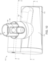
- the cleaner head preferably comprises a bottom surface, or sole plate, in which the opening is formed.
- the longitudinal axis of the agitator is preferably inclined at an acute angle to a plane containing the opening of the cleaner head. In a preferred embodiment the acute angle is 7°, whereas in another embodiment the acute angle is 5°.
- the lowermost portion of the external surface of the core is preferably parallel to the plane containing the opening so that the lowermost portion of the external surface of the core is evenly spaced along its length from this plane.
- the opening is preferably trapezoidal in shape.
- the opening may be defined by a relatively long leading edge, and relatively long trailing edge, and two side edges each extending between the leading edge and the trailing edge.
- the leading edge may be perpendicular to the side edges, or, as in a preferred embodiment, it may be inclined relative to the side edges so that it subtends an acute angle with one side edge and an obtuse angle with the other side edge.
- the suction cavity is preferably defined by a conical housing of the cleaner head.
- the housing may be formed from a plurality of housing sections.
- the housing preferably has substantially the same shape as the agitator.
- a housing section may be pivotable relative to the sole plate as the cleaner head is manoeuvred over a floor surface. This can reduce the risk of the sole plate becoming lifted away from the floor surface as it is manoeuvred over the floor surface, and so reducing the suction of the cleaner head.
- the airflow path is preferably defined, at least in part, by a neck for conveying air from the air outlet to the outlet of the cleaner head.
- the neck preferably comprises a connector for connecting the cleaner head to a vacuum cleaner.
- the airflow path is also preferably defined, at least in part, by a duct for conveying air from the air outlet to an air inlet port formed in the neck.
- the duct, and thus the airflow path preferably extends externally of the housing from the air outlet to the neck.
- the duct is preferably curved, and preferably curves through 90° between the air outlet and the air inlet port.
- the duct may have a constant or a varying radius of curvature along its length.
- the duct is preferably integral with at least part of the neck and/or at least part of the housing.
- the second airflow path is preferably defined, at least in part, by a duct for conveying air from the second air outlet to an air inlet port formed in the neck and from which the second part of the airflow enters the first part of the airflow.
- the air inlet port is located between the first air outlet and the outlet of the cleaner head. The second airflow path thus extends away from the suction cavity in parallel to the portion of the first airflow path located upstream from the air inlet port.
- the cleaner head preferably comprises an agitator engaging member for pressing against the agitator any debris which has become wrapped around the agitator.
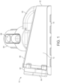
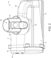
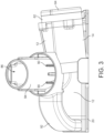
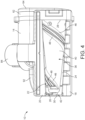
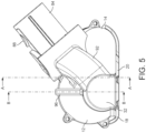
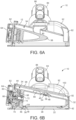
- FIGS 1 to 5 are external views of a first embodiment of a cleaner head 10 for a vacuum cleaner.
- the cleaner head 10 comprises a conical front housing 12, a rear housing 14 connected to the front housing 12, and a sole plate 16 connected to the front housing 12.
- One or more of the rear housing 14 and the sole plate 16 may be integral with the front housing 12, and are preferably formed from plastics material. In use, the sole plate 16 is placed upon the floor surface to be cleaned.
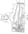
- the front housing 12 defines a conical suction cavity 34 which receives the airflow drawn into the cleaner head 10 through the suction opening 22.
- the suction cavity 34 houses an agitator 36 for agitating the fibres of a carpeted floor surface.
- the agitator 36 is in the form of a brush bar which is rotatable relative to the front housing 12, and suction cavity 34, about an axis which is collinear with the longitudinal axis of the agitator 36.
- the agitator 36 comprises a hollow core 38, which in this embodiment is conical in shape.
- a pair of helical ridges 46, 48 are upstanding from the external surface 40 of the core 38, and extend helically along the external surface 40 of the core 38 from the second end 44 to the first end 42 thereof.
- the ridges 46, 48 extend substantially the entire length of the core 38, and extend about the external surface 40 by around 450°.
- the ridges 46, 48 are preferably integral with the core 38 so that the ridges 46, 48 do not deform excessively upon contact with a floor surface.
- the ridges 46, 48 define a helical channel 50 therebetween which receives a bristle strip 52 (not shown in Figure 4 ).
- the bristle strip 52 comprises a flexible bristle base 54 and a row of bristles 56 woven into the bristle strip 54.
- Such debris is encouraged by the conical shape of the agitator 136 to migrate along the length of the agitator 136 from the second end 144 towards the first end 142. Under the action of the engaging member 196, such debris is pressed around the agitator 136 until it falls from the first end 412 of the agitator 136, whereupon the released debris becomes entrained within the airflow and passes through the duct 192 and into the neck 184 of the cleaner head 10.
- the inclination of the bristles 156 relative to the external surface 140 of the core 138 encourages the wrapped debris to migrate along the agitator 136.
Landscapes
- Engineering & Computer Science (AREA)
- Mechanical Engineering (AREA)
- Nozzles For Electric Vacuum Cleaners (AREA)
Claims (21)
- Reinigungskopf (10, 110) für einen Staubsauger, wobei der Reinigungskopf (10, 110) Folgendes umfasst:einen Ansaughohlraum (34, 134), umfassend eine Öffnung (22, 122), durch welche Schmutz in den Reinigungskopf (10, 110) eintritt, und einen Luftauslass (82, 182); undein Rührwerk (36, 136), das zur Drehung in Bezug dazu auskragend an dem Ansaughohlraum (34, 134) montiert ist, wobei das Rührwerk (36, 136) konisch geformt ist und ein erstes, freies Ende (42, 142) und ein zweites Ende (44, 144), das einen größeren Durchmesser als das erste Ende (42, 142) aufweist, aufweist;dadurch gekennzeichnet, dass der Luftauslass (82, 182) an das freie Ende (42, 142) des Rührwerks (36, 136) angrenzend angeordnet ist.
- Reinigungskopf (10, 110) nach Anspruch 1, wobei der Luftauslass (82, 182) hinter dem Rührwerk (36, 136) angeordnet ist.
- Reinigungskopf (10, 110) nach Anspruch 1 oder Anspruch 2, wobei der Luftauslass (82, 182) derart positioniert ist, dass der Luftauslass (82, 182) in eine Richtung, die sich entlang der Längsachse des Rührwerks (36, 136) erstreckt, vom freien Ende (42, 142) des Rührwerks (36, 136) beabstandet ist.
- Reinigungskopf (10, 110) nach Anspruch 3, wobei der Abstand des Luftauslasses (82, 182) vom Rührwerk (36, 136) entlang der Richtung weniger als 10 mm beträgt.
- Reinigungskopf (10, 110) nach einem der vorstehenden Ansprüche, umfassend einen Hals (84, 184), der mit einem Staubsauger verbindbar ist, und wobei der Hals (84, 184) einen Auslass (86, 186) des Reinigungskopfes (10, 110) umfasst.
- Reinigungskopf (10, 110) nach Anspruch 5, wobei der Reinigungskopf (10, 110) einen Luftströmungsweg definiert, der sich dem Ansaughohlraum (34, 134) nachgelagert vom Luftauslass (82, 182) zum Auslass (86, 186) des Reinigungskopfes (10, 110) erstreckt.
- Reinigungskopf (10, 110) nach Anspruch 6, wobei der Luftströmungsweg zumindest teilweise durch einen Kanal (92, 192) zum Befördern von Luft vom Luftauslass (82, 182) zu einem im Hals (84, 184) ausgebildeten Lufteinlassanschluss definiert ist.
- Reinigungskopf (10, 110) nach Anspruch 7, wobei der Ansaughohlraum (34, 134) durch ein Gehäuse (12, 112) des Reinigungskopfes (10, 110) definiert ist und wobei sich der Kanal (92, 192) außerhalb des Gehäuses (12, 112) vom Luftauslass (82, 182) zum Hals (84, 184) erstreckt.
- Reinigungskopf (10, 110) nach Anspruch 8, wobei das Gehäuse (12, 112) im Wesentlichen konisch geformt ist.
- Reinigungskopf (10, 110) nach einem der Ansprüche 7 bis 9, wobei der Kanal (92, 192) gekrümmt ist.
- Reinigungskopf (10, 110) nach Anspruch 10, wobei der Kanal (92, 192) zwischen dem Luftauslass (82, 182) und dem Lufteinlassanschluss über 90° gekrümmt ist.
- Reinigungskopf (10, 110) nach einem der Ansprüche 7 bis 11, wobei der Kanal (92, 192) zumindest in einen Teil des Halses (84, 184) integriert ist.
- Reinigungskopf (10, 110) nach einem der Ansprüche 7 bis 12, wobei der Kanal (92, 192) zumindest in einen Teil des Gehäuses (12, 112) integriert ist.
- Reinigungskopf (10) nach einem der vorstehenden Ansprüche, wobei der Ansaughohlraum (34) einen zusätzlichen Luftauslass (80) umfasst und der Reinigungskopf einen zusätzlichen Luftströmungsweg definiert, der sich dem Ansaughohlraum (34) nachgelagert vom zusätzlichen Luftauslass (80) zu einem Auslass (86) des Reinigungskopfes erstreckt.
- Reinigungskopf (10) nach Anspruch 14, wobei der zusätzliche Luftauslass (80) hinter dem Rührwerk (36) angeordnet ist.
- Reinigungskopf (10) nach Anspruch 14 oder Anspruch 15, wobei der zusätzliche Luftauslass (80) mittig zwischen dem freien Ende (42) und dem zweiten Ende (44) des Rührwerks (36) angeordnet ist.
- Reinigungskopf (10) nach einem der Ansprüche 14 bis 16, wobei die Luftauslässe (80, 82) in eine Richtung ausgerichtet sind, die sich parallel zur Längsachse des Rührwerks (36) erstreckt.
- Reinigungskopf (10) nach einem der Ansprüche 14 bis 17, wenn abhängig von Anspruch 6, wobei der sich vom Luftauslass (82) erstreckende Luftströmungsweg den dem Auslass (86) des Reinigungskopfes (10, 110) vorgelagerten Luftströmungsweg schneidet.
- Reinigungskopf (10, 110) nach einem der vorstehenden Ansprüche, umfassend einen Antrieb zum Antreiben der Drehung des Rührwerks (36, 136) und wobei das Rührwerk (36, 136) am zweiten Ende (44, 144) des Rührwerks (36, 136) oder in der Nähe davon mit dem Antrieb verbunden ist.
- Reinigungskopf (10, 110) nach Anspruch 19, wobei der Antrieb einen Motor (160), der außerhalb des Rührwerks (36, 136) angeordnet ist, und einen Riemen (60), der das Rührwerk (36, 136) mit dem Motor (160) verbindet, umfasst.
- Reinigungskopf (10, 110) nach einem der vorstehenden Ansprüche, wobei das Rührwerk (36, 136) einen konischen Kern (38, 138) umfasst, der aufrechte, schraubenförmige Rippen (46, 48) und eine Reihe von Borsten (56, 156), die zwischen den schraubenförmigen Rippen (46, 48) angeordnet sind, aufweist.
Applications Claiming Priority (3)
| Application Number | Priority Date | Filing Date | Title |
|---|---|---|---|
| GBGB1907851.8A GB201907851D0 (en) | 2019-06-03 | 2019-06-03 | A cleaner head for a vacuum cleaner |
| GB2002358.6A GB2584521B (en) | 2019-06-03 | 2020-02-20 | A cleaner head for a vacuum cleaner |
| PCT/GB2020/050968 WO2020245561A1 (en) | 2019-06-03 | 2020-04-17 | A cleaner head for a vacuum cleaner |
Publications (2)
| Publication Number | Publication Date |
|---|---|
| EP3975813A1 EP3975813A1 (de) | 2022-04-06 |
| EP3975813B1 true EP3975813B1 (de) | 2024-07-10 |
Family
ID=67385874
Family Applications (1)
| Application Number | Title | Priority Date | Filing Date |
|---|---|---|---|
| EP20721706.8A Active EP3975813B1 (de) | 2019-06-03 | 2020-04-17 | Ein staubsaugerkopf für einen staubsauger |
Country Status (8)
| Country | Link |
|---|---|
| US (1) | US12376718B2 (de) |
| EP (1) | EP3975813B1 (de) |
| JP (1) | JP7355855B2 (de) |
| KR (1) | KR102700478B1 (de) |
| CN (1) | CN113905648A (de) |
| GB (2) | GB201907851D0 (de) |
| SG (1) | SG11202111485SA (de) |
| WO (1) | WO2020245561A1 (de) |
Families Citing this family (24)
| Publication number | Priority date | Publication date | Assignee | Title |
|---|---|---|---|---|
| US10820772B2 (en) | 2017-09-15 | 2020-11-03 | Omachron Intellectual Property Inc. | Surface cleaning apparatus |
| JP7499193B2 (ja) * | 2021-01-14 | 2024-06-13 | シャープ株式会社 | 電気掃除機 |
| CN215457628U (zh) * | 2021-03-16 | 2022-01-11 | 北京石头世纪科技股份有限公司 | 一种清洁工具及清洁设备 |
| GB2619034B (en) * | 2022-05-24 | 2024-10-30 | Dyson Technology Ltd | Agitator element for a vacuum cleaner |
| GB2620119B (en) * | 2022-06-27 | 2024-09-25 | Dyson Technology Ltd | Vacuum cleaner head having agitator element and rib |
| CN116236087A (zh) * | 2022-08-04 | 2023-06-09 | 北京顺造科技有限公司 | 地刷组件及表面清洁设备 |
| USD1059709S1 (en) * | 2022-08-31 | 2025-01-28 | Dyson Technology Limited | Vacuum cleaner head |
| JP1756694S (ja) * | 2022-08-31 | 2024-05-10 | 電気掃除機用吸込み口 | |
| JP1756693S (ja) * | 2022-08-31 | 2024-05-10 | 電気掃除機用吸込み口 | |
| USD1069299S1 (en) * | 2022-08-31 | 2025-04-01 | Dyson Technology Limited | Vacuum cleaner head |
| USD1069288S1 (en) * | 2022-08-31 | 2025-04-01 | Dyson Technology Limited | Vacuum cleaner head |
| USD1069290S1 (en) * | 2022-08-31 | 2025-04-01 | Dyson Technology Limited | Vacuum cleaner roller |
| USD1069292S1 (en) * | 2022-08-31 | 2025-04-01 | Dyson Technology Limited | Vacuum cleaner roller |
| JP1756695S (ja) * | 2022-08-31 | 2024-05-10 | 電気掃除機用吸込み口 | |
| JP1756691S (ja) * | 2022-08-31 | 2024-05-10 | 電気掃除機用吸込み口 | |
| USD1069293S1 (en) * | 2022-08-31 | 2025-04-01 | Dyson Technology Limited | Vacuum cleaner head |
| USD1069298S1 (en) * | 2022-08-31 | 2025-04-01 | Dyson Technology Limited | Vacuum cleaner head |
| JP1756692S (ja) * | 2022-08-31 | 2024-05-10 | 電気掃除機用吸込み口 | |
| USD1069291S1 (en) * | 2022-08-31 | 2025-04-01 | Dyson Technology Limited | Vacuum cleaner head |
| USD1069287S1 (en) * | 2022-08-31 | 2025-04-01 | Dyson Technology Limited | Vacuum cleaner head |
| USD1069289S1 (en) * | 2022-08-31 | 2025-04-01 | Dyson Technology Limited | Vacuum cleaner roller |
| EP4716491A1 (de) | 2023-05-23 | 2026-04-01 | SharkNinja Operating LLC | Reinigungsgerät |
| USD1105672S1 (en) * | 2023-08-30 | 2025-12-09 | Sharkninja Operating Llc | Vacuum cleaner and vacuum nozzle |
| USD1113019S1 (en) | 2024-05-31 | 2026-02-10 | Sharkninja Operating Llc | Steam cleaner |
Family Cites Families (30)
| Publication number | Priority date | Publication date | Assignee | Title |
|---|---|---|---|---|
| GB364362A (en) * | 1930-04-05 | 1932-01-07 | Wilhelm Mauz | Improvements in vacuum cleaners |
| GB513909A (en) * | 1938-03-21 | 1939-10-25 | Sidney Peter Jackson | Improvements in and relating to machines for surfacing floors and the like |
| US2283428A (en) | 1940-10-10 | 1942-05-19 | Philip B Ellis | Nozzle for vacuum cleaners |
| DE1428388A1 (de) * | 1963-04-30 | 1968-12-12 | Electrostar Gmbh | Reinigungsvorrichtung fuer Schuhzeug,Polsterungen od.dgl. |
| US4426751A (en) | 1982-01-21 | 1984-01-24 | Whirlpool Corporation | Vacuum cleaner nozzle with double brush |
| JPH02149239A (ja) | 1988-12-01 | 1990-06-07 | Hookii:Kk | 掃除機 |
| IT1291839B1 (it) | 1997-04-28 | 1999-01-21 | Renzo Scarselli | Un sistema di spazzole per una macchina per la pulizia di pavimenti e/o di tappeti, moquettes o simili ed una spazzola per tale sistema |
| JP2823013B2 (ja) * | 1997-11-21 | 1998-11-11 | 株式会社日立製作所 | 電気掃除機及びその吸口体 |
| JP2001252227A (ja) * | 2000-03-09 | 2001-09-18 | Matsushita Electric Ind Co Ltd | 電気掃除機用吸込具及びそれを用いた電気掃除機 |
| KR100504919B1 (ko) | 2003-06-05 | 2005-07-29 | 엘지전자 주식회사 | 청소기의 흡입노즐 구조 |
| JP2005065821A (ja) * | 2003-08-21 | 2005-03-17 | Mitsubishi Electric Corp | 電気掃除機および電気掃除機用吸込口体 |
| KR100556811B1 (ko) | 2004-06-12 | 2006-03-10 | 엘지전자 주식회사 | 진공청소기의 흡입헤드 |
| KR100595558B1 (ko) | 2004-06-12 | 2006-07-03 | 엘지전자 주식회사 | 진공청소기의 흡입헤드 |
| KR100613102B1 (ko) | 2004-07-01 | 2006-08-17 | 삼성광주전자 주식회사 | 흡입구조립체와 이를 구비한 진공청소기 |
| JP2006026222A (ja) * | 2004-07-20 | 2006-02-02 | Toshiba Tec Corp | 回転清掃体と電気掃除機 |
| GB2428113B (en) | 2005-07-07 | 2007-06-20 | Visteon Global Tech Inc | Electronic timekeeping apparatus |
| US8621709B2 (en) * | 2006-12-12 | 2014-01-07 | G.B.D. Corp. | Multi-strut cleaning head |
| KR101457162B1 (ko) | 2007-11-16 | 2014-11-03 | 삼성전자 주식회사 | 진공청소기 |
| CA2658369A1 (en) * | 2009-03-13 | 2010-09-13 | G.B.D. Corp. | Surface cleaning head |
| US8434194B2 (en) | 2009-05-15 | 2013-05-07 | Lg Electronics Inc. | Nozzle for a vacuum cleaner |
| GB2482026B (en) * | 2010-07-16 | 2015-06-17 | Dyson Technology Ltd | A vacuum cleaning appliance |
| JP5923681B2 (ja) * | 2011-06-29 | 2016-05-25 | パナソニックIpマネジメント株式会社 | 電気掃除機用の吸込具およびそれを用いた電気掃除機 |
| JP2013102861A (ja) * | 2011-11-11 | 2013-05-30 | Toshiba Corp | 電気掃除機およびその吸込口体 |
| CN104622388B (zh) | 2013-11-12 | 2018-01-30 | 江苏美的清洁电器股份有限公司 | 吸尘器及其地刷 |
| GB2543314B (en) * | 2015-10-14 | 2018-02-21 | Dyson Technology Ltd | Cleaner head for a vacuum cleaner |
| CN205625807U (zh) * | 2016-02-25 | 2016-10-12 | 飞利浦(中国)投资有限公司 | 刷子、用于吸尘器的吸嘴以及吸尘器 |
| CN118806047A (zh) * | 2016-09-09 | 2024-10-22 | 尚科宁家运营有限公司 | 除毛搅拌器 |
| CN208447449U (zh) * | 2017-10-24 | 2019-02-01 | 无锡睿米信息技术有限公司 | 一种地刷 |
| GB2569313B (en) * | 2017-12-12 | 2020-10-28 | Dyson Technology Ltd | A cleaner head for a vacuum cleaner |
| WO2019209879A1 (en) * | 2018-04-23 | 2019-10-31 | Sharkninja Operating Llc | Assisted drive for surface cleaning devices |
-
2019
- 2019-06-03 GB GBGB1907851.8A patent/GB201907851D0/en not_active Ceased
-
2020
- 2020-02-20 GB GB2002358.6A patent/GB2584521B/en active Active
- 2020-04-17 WO PCT/GB2020/050968 patent/WO2020245561A1/en not_active Ceased
- 2020-04-17 CN CN202080040711.5A patent/CN113905648A/zh active Pending
- 2020-04-17 US US17/612,997 patent/US12376718B2/en active Active
- 2020-04-17 JP JP2021571809A patent/JP7355855B2/ja active Active
- 2020-04-17 EP EP20721706.8A patent/EP3975813B1/de active Active
- 2020-04-17 SG SG11202111485SA patent/SG11202111485SA/en unknown
- 2020-04-17 KR KR1020217043255A patent/KR102700478B1/ko active Active
Also Published As
| Publication number | Publication date |
|---|---|
| EP3975813A1 (de) | 2022-04-06 |
| US12376718B2 (en) | 2025-08-05 |
| GB2584521B (en) | 2021-10-06 |
| WO2020245561A1 (en) | 2020-12-10 |
| KR102700478B1 (ko) | 2024-08-30 |
| CN113905648A (zh) | 2022-01-07 |
| JP2022535082A (ja) | 2022-08-04 |
| GB201907851D0 (en) | 2019-07-17 |
| GB202002358D0 (en) | 2020-04-08 |
| GB2584521A (en) | 2020-12-09 |
| SG11202111485SA (en) | 2021-11-29 |
| JP7355855B2 (ja) | 2023-10-03 |
| US20220211232A1 (en) | 2022-07-07 |
| KR20220015467A (ko) | 2022-02-08 |
Similar Documents
| Publication | Publication Date | Title |
|---|---|---|
| EP3975813B1 (de) | Ein staubsaugerkopf für einen staubsauger | |
| EP3975811B1 (de) | Einen staubsaugerkopf für einen staubsauger | |
| EP3975812B1 (de) | Ein staubsaugerkopf für einen staubsauger | |
| EP2440099B2 (de) | Reinigungsvorrichtungskopf | |
| EP2521475B1 (de) | Saugkopf | |
| EP2440098B1 (de) | Reinigungskopf | |
| EP2521476B1 (de) | Saugkopf | |
| WO2025233832A1 (en) | Cleaner head | |
| GB2642952A (en) | Cleaner head |
Legal Events
| Date | Code | Title | Description |
|---|---|---|---|
| STAA | Information on the status of an ep patent application or granted ep patent |
Free format text: STATUS: UNKNOWN |
|
| STAA | Information on the status of an ep patent application or granted ep patent |
Free format text: STATUS: THE INTERNATIONAL PUBLICATION HAS BEEN MADE |
|
| PUAI | Public reference made under article 153(3) epc to a published international application that has entered the european phase |
Free format text: ORIGINAL CODE: 0009012 |
|
| STAA | Information on the status of an ep patent application or granted ep patent |
Free format text: STATUS: REQUEST FOR EXAMINATION WAS MADE |
|
| 17P | Request for examination filed |
Effective date: 20211014 |
|
| AK | Designated contracting states |
Kind code of ref document: A1 Designated state(s): AL AT BE BG CH CY CZ DE DK EE ES FI FR GB GR HR HU IE IS IT LI LT LU LV MC MK MT NL NO PL PT RO RS SE SI SK SM TR |
|
| DAV | Request for validation of the european patent (deleted) | ||
| DAX | Request for extension of the european patent (deleted) | ||
| GRAP | Despatch of communication of intention to grant a patent |
Free format text: ORIGINAL CODE: EPIDOSNIGR1 |
|
| STAA | Information on the status of an ep patent application or granted ep patent |
Free format text: STATUS: GRANT OF PATENT IS INTENDED |
|
| INTG | Intention to grant announced |
Effective date: 20240207 |
|
| GRAS | Grant fee paid |
Free format text: ORIGINAL CODE: EPIDOSNIGR3 |
|
| GRAA | (expected) grant |
Free format text: ORIGINAL CODE: 0009210 |
|
| STAA | Information on the status of an ep patent application or granted ep patent |
Free format text: STATUS: THE PATENT HAS BEEN GRANTED |
|
| AK | Designated contracting states |
Kind code of ref document: B1 Designated state(s): AL AT BE BG CH CY CZ DE DK EE ES FI FR GB GR HR HU IE IS IT LI LT LU LV MC MK MT NL NO PL PT RO RS SE SI SK SM TR |
|
| P01 | Opt-out of the competence of the unified patent court (upc) registered |
Free format text: CASE NUMBER: APP_33443/2024 Effective date: 20240605 |
|
| REG | Reference to a national code |
Ref country code: CH Ref legal event code: EP |
|
| REG | Reference to a national code |
Ref country code: DE Ref legal event code: R096 Ref document number: 602020033731 Country of ref document: DE |
|
| REG | Reference to a national code |
Ref country code: LT Ref legal event code: MG9D |
|
| REG | Reference to a national code |
Ref country code: NL Ref legal event code: MP Effective date: 20240710 |
|
| PG25 | Lapsed in a contracting state [announced via postgrant information from national office to epo] |
Ref country code: PT Free format text: LAPSE BECAUSE OF FAILURE TO SUBMIT A TRANSLATION OF THE DESCRIPTION OR TO PAY THE FEE WITHIN THE PRESCRIBED TIME-LIMIT Effective date: 20241111 |
|
| REG | Reference to a national code |
Ref country code: AT Ref legal event code: MK05 Ref document number: 1701245 Country of ref document: AT Kind code of ref document: T Effective date: 20240710 |
|
| PG25 | Lapsed in a contracting state [announced via postgrant information from national office to epo] |
Ref country code: NL Free format text: LAPSE BECAUSE OF FAILURE TO SUBMIT A TRANSLATION OF THE DESCRIPTION OR TO PAY THE FEE WITHIN THE PRESCRIBED TIME-LIMIT Effective date: 20240710 |
|
| PG25 | Lapsed in a contracting state [announced via postgrant information from national office to epo] |
Ref country code: PT Free format text: LAPSE BECAUSE OF FAILURE TO SUBMIT A TRANSLATION OF THE DESCRIPTION OR TO PAY THE FEE WITHIN THE PRESCRIBED TIME-LIMIT Effective date: 20241111 Ref country code: NL Free format text: LAPSE BECAUSE OF FAILURE TO SUBMIT A TRANSLATION OF THE DESCRIPTION OR TO PAY THE FEE WITHIN THE PRESCRIBED TIME-LIMIT Effective date: 20240710 |
|
| PG25 | Lapsed in a contracting state [announced via postgrant information from national office to epo] |
Ref country code: NO Free format text: LAPSE BECAUSE OF FAILURE TO SUBMIT A TRANSLATION OF THE DESCRIPTION OR TO PAY THE FEE WITHIN THE PRESCRIBED TIME-LIMIT Effective date: 20241010 |
|
| PG25 | Lapsed in a contracting state [announced via postgrant information from national office to epo] |
Ref country code: GR Free format text: LAPSE BECAUSE OF FAILURE TO SUBMIT A TRANSLATION OF THE DESCRIPTION OR TO PAY THE FEE WITHIN THE PRESCRIBED TIME-LIMIT Effective date: 20241011 Ref country code: PL Free format text: LAPSE BECAUSE OF FAILURE TO SUBMIT A TRANSLATION OF THE DESCRIPTION OR TO PAY THE FEE WITHIN THE PRESCRIBED TIME-LIMIT Effective date: 20240710 Ref country code: FI Free format text: LAPSE BECAUSE OF FAILURE TO SUBMIT A TRANSLATION OF THE DESCRIPTION OR TO PAY THE FEE WITHIN THE PRESCRIBED TIME-LIMIT Effective date: 20240710 |
|
| PG25 | Lapsed in a contracting state [announced via postgrant information from national office to epo] |
Ref country code: BG Free format text: LAPSE BECAUSE OF FAILURE TO SUBMIT A TRANSLATION OF THE DESCRIPTION OR TO PAY THE FEE WITHIN THE PRESCRIBED TIME-LIMIT Effective date: 20240710 |
|
| PG25 | Lapsed in a contracting state [announced via postgrant information from national office to epo] |
Ref country code: LV Free format text: LAPSE BECAUSE OF FAILURE TO SUBMIT A TRANSLATION OF THE DESCRIPTION OR TO PAY THE FEE WITHIN THE PRESCRIBED TIME-LIMIT Effective date: 20240710 |
|
| PG25 | Lapsed in a contracting state [announced via postgrant information from national office to epo] |
Ref country code: AT Free format text: LAPSE BECAUSE OF FAILURE TO SUBMIT A TRANSLATION OF THE DESCRIPTION OR TO PAY THE FEE WITHIN THE PRESCRIBED TIME-LIMIT Effective date: 20240710 Ref country code: IS Free format text: LAPSE BECAUSE OF FAILURE TO SUBMIT A TRANSLATION OF THE DESCRIPTION OR TO PAY THE FEE WITHIN THE PRESCRIBED TIME-LIMIT Effective date: 20241110 |
|
| PG25 | Lapsed in a contracting state [announced via postgrant information from national office to epo] |
Ref country code: HR Free format text: LAPSE BECAUSE OF FAILURE TO SUBMIT A TRANSLATION OF THE DESCRIPTION OR TO PAY THE FEE WITHIN THE PRESCRIBED TIME-LIMIT Effective date: 20240710 |
|
| PG25 | Lapsed in a contracting state [announced via postgrant information from national office to epo] |
Ref country code: ES Free format text: LAPSE BECAUSE OF FAILURE TO SUBMIT A TRANSLATION OF THE DESCRIPTION OR TO PAY THE FEE WITHIN THE PRESCRIBED TIME-LIMIT Effective date: 20240710 Ref country code: RS Free format text: LAPSE BECAUSE OF FAILURE TO SUBMIT A TRANSLATION OF THE DESCRIPTION OR TO PAY THE FEE WITHIN THE PRESCRIBED TIME-LIMIT Effective date: 20241010 |
|
| PG25 | Lapsed in a contracting state [announced via postgrant information from national office to epo] |
Ref country code: RS Free format text: LAPSE BECAUSE OF FAILURE TO SUBMIT A TRANSLATION OF THE DESCRIPTION OR TO PAY THE FEE WITHIN THE PRESCRIBED TIME-LIMIT Effective date: 20241010 Ref country code: PL Free format text: LAPSE BECAUSE OF FAILURE TO SUBMIT A TRANSLATION OF THE DESCRIPTION OR TO PAY THE FEE WITHIN THE PRESCRIBED TIME-LIMIT Effective date: 20240710 Ref country code: NO Free format text: LAPSE BECAUSE OF FAILURE TO SUBMIT A TRANSLATION OF THE DESCRIPTION OR TO PAY THE FEE WITHIN THE PRESCRIBED TIME-LIMIT Effective date: 20241010 Ref country code: LV Free format text: LAPSE BECAUSE OF FAILURE TO SUBMIT A TRANSLATION OF THE DESCRIPTION OR TO PAY THE FEE WITHIN THE PRESCRIBED TIME-LIMIT Effective date: 20240710 Ref country code: IS Free format text: LAPSE BECAUSE OF FAILURE TO SUBMIT A TRANSLATION OF THE DESCRIPTION OR TO PAY THE FEE WITHIN THE PRESCRIBED TIME-LIMIT Effective date: 20241110 Ref country code: HR Free format text: LAPSE BECAUSE OF FAILURE TO SUBMIT A TRANSLATION OF THE DESCRIPTION OR TO PAY THE FEE WITHIN THE PRESCRIBED TIME-LIMIT Effective date: 20240710 Ref country code: GR Free format text: LAPSE BECAUSE OF FAILURE TO SUBMIT A TRANSLATION OF THE DESCRIPTION OR TO PAY THE FEE WITHIN THE PRESCRIBED TIME-LIMIT Effective date: 20241011 Ref country code: FI Free format text: LAPSE BECAUSE OF FAILURE TO SUBMIT A TRANSLATION OF THE DESCRIPTION OR TO PAY THE FEE WITHIN THE PRESCRIBED TIME-LIMIT Effective date: 20240710 Ref country code: ES Free format text: LAPSE BECAUSE OF FAILURE TO SUBMIT A TRANSLATION OF THE DESCRIPTION OR TO PAY THE FEE WITHIN THE PRESCRIBED TIME-LIMIT Effective date: 20240710 Ref country code: BG Free format text: LAPSE BECAUSE OF FAILURE TO SUBMIT A TRANSLATION OF THE DESCRIPTION OR TO PAY THE FEE WITHIN THE PRESCRIBED TIME-LIMIT Effective date: 20240710 Ref country code: AT Free format text: LAPSE BECAUSE OF FAILURE TO SUBMIT A TRANSLATION OF THE DESCRIPTION OR TO PAY THE FEE WITHIN THE PRESCRIBED TIME-LIMIT Effective date: 20240710 |
|
| REG | Reference to a national code |
Ref country code: DE Ref legal event code: R097 Ref document number: 602020033731 Country of ref document: DE |
|
| PG25 | Lapsed in a contracting state [announced via postgrant information from national office to epo] |
Ref country code: RO Free format text: LAPSE BECAUSE OF FAILURE TO SUBMIT A TRANSLATION OF THE DESCRIPTION OR TO PAY THE FEE WITHIN THE PRESCRIBED TIME-LIMIT Effective date: 20240710 Ref country code: SM Free format text: LAPSE BECAUSE OF FAILURE TO SUBMIT A TRANSLATION OF THE DESCRIPTION OR TO PAY THE FEE WITHIN THE PRESCRIBED TIME-LIMIT Effective date: 20240710 Ref country code: DK Free format text: LAPSE BECAUSE OF FAILURE TO SUBMIT A TRANSLATION OF THE DESCRIPTION OR TO PAY THE FEE WITHIN THE PRESCRIBED TIME-LIMIT Effective date: 20240710 |
|
| PG25 | Lapsed in a contracting state [announced via postgrant information from national office to epo] |
Ref country code: EE Free format text: LAPSE BECAUSE OF FAILURE TO SUBMIT A TRANSLATION OF THE DESCRIPTION OR TO PAY THE FEE WITHIN THE PRESCRIBED TIME-LIMIT Effective date: 20240710 |
|
| PG25 | Lapsed in a contracting state [announced via postgrant information from national office to epo] |
Ref country code: CZ Free format text: LAPSE BECAUSE OF FAILURE TO SUBMIT A TRANSLATION OF THE DESCRIPTION OR TO PAY THE FEE WITHIN THE PRESCRIBED TIME-LIMIT Effective date: 20240710 |
|
| PG25 | Lapsed in a contracting state [announced via postgrant information from national office to epo] |
Ref country code: IT Free format text: LAPSE BECAUSE OF FAILURE TO SUBMIT A TRANSLATION OF THE DESCRIPTION OR TO PAY THE FEE WITHIN THE PRESCRIBED TIME-LIMIT Effective date: 20240710 Ref country code: SK Free format text: LAPSE BECAUSE OF FAILURE TO SUBMIT A TRANSLATION OF THE DESCRIPTION OR TO PAY THE FEE WITHIN THE PRESCRIBED TIME-LIMIT Effective date: 20240710 |
|
| PLBE | No opposition filed within time limit |
Free format text: ORIGINAL CODE: 0009261 |
|
| STAA | Information on the status of an ep patent application or granted ep patent |
Free format text: STATUS: NO OPPOSITION FILED WITHIN TIME LIMIT |
|
| 26N | No opposition filed |
Effective date: 20250411 |
|
| PGFP | Annual fee paid to national office [announced via postgrant information from national office to epo] |
Ref country code: DE Payment date: 20250319 Year of fee payment: 6 |
|
| PG25 | Lapsed in a contracting state [announced via postgrant information from national office to epo] |
Ref country code: SE Free format text: LAPSE BECAUSE OF FAILURE TO SUBMIT A TRANSLATION OF THE DESCRIPTION OR TO PAY THE FEE WITHIN THE PRESCRIBED TIME-LIMIT Effective date: 20240710 |
|
| REG | Reference to a national code |
Ref country code: CH Ref legal event code: H13 Free format text: ST27 STATUS EVENT CODE: U-0-0-H10-H13 (AS PROVIDED BY THE NATIONAL OFFICE) Effective date: 20251125 |
|
| PG25 | Lapsed in a contracting state [announced via postgrant information from national office to epo] |
Ref country code: LU Free format text: LAPSE BECAUSE OF NON-PAYMENT OF DUE FEES Effective date: 20250417 |
|
| PG25 | Lapsed in a contracting state [announced via postgrant information from national office to epo] |
Ref country code: MC Free format text: LAPSE BECAUSE OF FAILURE TO SUBMIT A TRANSLATION OF THE DESCRIPTION OR TO PAY THE FEE WITHIN THE PRESCRIBED TIME-LIMIT Effective date: 20240710 |
|
| REG | Reference to a national code |
Ref country code: BE Ref legal event code: MM Effective date: 20250430 |
|
| PG25 | Lapsed in a contracting state [announced via postgrant information from national office to epo] |
Ref country code: BE Free format text: LAPSE BECAUSE OF NON-PAYMENT OF DUE FEES Effective date: 20250430 |
|
| PG25 | Lapsed in a contracting state [announced via postgrant information from national office to epo] |
Ref country code: CH Free format text: LAPSE BECAUSE OF NON-PAYMENT OF DUE FEES Effective date: 20250430 |
|
| PGFP | Annual fee paid to national office [announced via postgrant information from national office to epo] |
Ref country code: GB Payment date: 20260205 Year of fee payment: 7 |
|
| PG25 | Lapsed in a contracting state [announced via postgrant information from national office to epo] |
Ref country code: IE Free format text: LAPSE BECAUSE OF NON-PAYMENT OF DUE FEES Effective date: 20250417 |
|
| PGFP | Annual fee paid to national office [announced via postgrant information from national office to epo] |
Ref country code: FR Payment date: 20260320 Year of fee payment: 7 |