EP3975645B1 - Wireless communication method and terminal device - Google Patents
Wireless communication method and terminal device Download PDFInfo
- Publication number
- EP3975645B1 EP3975645B1 EP20831270.2A EP20831270A EP3975645B1 EP 3975645 B1 EP3975645 B1 EP 3975645B1 EP 20831270 A EP20831270 A EP 20831270A EP 3975645 B1 EP3975645 B1 EP 3975645B1
- Authority
- EP
- European Patent Office
- Prior art keywords
- terminal device
- sidelink
- message
- indication information
- present application
- Prior art date
- Legal status (The legal status is an assumption and is not a legal conclusion. Google has not performed a legal analysis and makes no representation as to the accuracy of the status listed.)
- Active
Links
Images

Classifications
-
- H—ELECTRICITY
- H04—ELECTRIC COMMUNICATION TECHNIQUE
- H04W—WIRELESS COMMUNICATION NETWORKS
- H04W76/00—Connection management
- H04W76/10—Connection setup
- H04W76/18—Management of setup rejection or failure
-
- H—ELECTRICITY
- H04—ELECTRIC COMMUNICATION TECHNIQUE
- H04W—WIRELESS COMMUNICATION NETWORKS
- H04W76/00—Connection management
- H04W76/30—Connection release
- H04W76/34—Selective release of ongoing connections
-
- H—ELECTRICITY
- H04—ELECTRIC COMMUNICATION TECHNIQUE
- H04W—WIRELESS COMMUNICATION NETWORKS
- H04W24/00—Supervisory, monitoring or testing arrangements
- H04W24/04—Arrangements for maintaining operational condition
-
- H—ELECTRICITY
- H04—ELECTRIC COMMUNICATION TECHNIQUE
- H04W—WIRELESS COMMUNICATION NETWORKS
- H04W24/00—Supervisory, monitoring or testing arrangements
- H04W24/08—Testing, supervising or monitoring using real traffic
-
- H—ELECTRICITY
- H04—ELECTRIC COMMUNICATION TECHNIQUE
- H04W—WIRELESS COMMUNICATION NETWORKS
- H04W28/00—Network traffic management; Network resource management
- H04W28/02—Traffic management, e.g. flow control or congestion control
- H04W28/0268—Traffic management, e.g. flow control or congestion control using specific QoS parameters for wireless networks, e.g. QoS class identifier [QCI] or guaranteed bit rate [GBR]
-
- H—ELECTRICITY
- H04—ELECTRIC COMMUNICATION TECHNIQUE
- H04W—WIRELESS COMMUNICATION NETWORKS
- H04W36/00—Hand-off or reselection arrangements
- H04W36/0005—Control or signalling for completing the hand-off
- H04W36/0055—Transmission or use of information for re-establishing the radio link
-
- H—ELECTRICITY
- H04—ELECTRIC COMMUNICATION TECHNIQUE
- H04W—WIRELESS COMMUNICATION NETWORKS
- H04W36/00—Hand-off or reselection arrangements
- H04W36/24—Reselection being triggered by specific parameters
- H04W36/30—Reselection being triggered by specific parameters by measured or perceived connection quality data
- H04W36/305—Handover due to radio link failure
-
- H—ELECTRICITY
- H04—ELECTRIC COMMUNICATION TECHNIQUE
- H04W—WIRELESS COMMUNICATION NETWORKS
- H04W72/00—Local resource management
- H04W72/20—Control channels or signalling for resource management
- H04W72/25—Control channels or signalling for resource management between terminals via a wireless link, e.g. sidelink
-
- H—ELECTRICITY
- H04—ELECTRIC COMMUNICATION TECHNIQUE
- H04W—WIRELESS COMMUNICATION NETWORKS
- H04W76/00—Connection management
- H04W76/10—Connection setup
- H04W76/19—Connection re-establishment
-
- H—ELECTRICITY
- H04—ELECTRIC COMMUNICATION TECHNIQUE
- H04W—WIRELESS COMMUNICATION NETWORKS
- H04W92/00—Interfaces specially adapted for wireless communication networks
- H04W92/16—Interfaces between hierarchically similar devices
- H04W92/18—Interfaces between hierarchically similar devices between terminal devices
-
- H—ELECTRICITY
- H04—ELECTRIC COMMUNICATION TECHNIQUE
- H04W—WIRELESS COMMUNICATION NETWORKS
- H04W76/00—Connection management
- H04W76/10—Connection setup
- H04W76/14—Direct-mode setup
Definitions
- Embodiments of the present application relate to the communication field, and more specifically, to a wireless communication method, a terminal device, a device and a computer-readable storage medium.
- a terminal device for example, a vehicle-mounted terminal
- more demands are required for the communication performance on the sidelink, and how to improve the communication performance on the sidelink is an urgent problem to be solved.
- VIVO "Open issues for Sidelink link failure and release", 3GPP Draft; R2-1905845
- LENOVO ET AL "Radio link maintenance for NR V2X unicast", 3GPP Draft; R2-1901002 , technologies regarding sidelink failure and radio link maintenance are discussed.
- Embodiments of the present application provide a wireless communication method and a terminal device, so that the terminal device can handle when an abnormality occurs in the sidelink, thereby improving the communication performance on the sidelink.
- a first aspect provides a wireless communication method as set out in claim 1. Additional features are shown in claims 2 to 12.
- a second aspect provides a terminal device as set out in claim 13.
- An aspect provides a device for implementing the method in various implementation manners of the first aspect.
- the device includes: a processor, configured to call and run a computer program from a memory, so that an apparatus installed with the device executes the method in various implementation manners of the first aspect.
- An aspect provides a computer-readable storage medium storing a computer program.
- the computer program enables a computer to execute the method in various implementation manners of the first aspect.
- the first terminal device in response to determining by the first terminal device that an abnormality has occurred on the sidelink between the first terminal device and a second terminal device, responds to the abnormality of the sidelink, thereby improving the communication performance on the sidelink.
- V2V vehicle to vehicle
- V2X vehicle to everything
- D2D Device to Device
- the terminal in embodiments of the present application may be any device or apparatus configured with a physical layer and a media access control layer, and the terminal device may also be referred to as an access terminal, for example, user equipment (UE), a subscriber unit, a subscriber station, a mobile station, a rover station, a remote station, a remote terminal, a mobile device, a user terminal, a terminal, a wireless communication device, a user agent, or a user device, etc.
- UE user equipment
- the access terminal can be a cellular phone, a cordless phone, a Session Initiation Protocol (SIP) phone, a wireless local loop (WLL) station, a personal digital linear processing (PDA), and a handheld device/computing device with wireless communication function or other linear processing devices connected to wireless modems, a vehicle-mounted device, a wearable device, etc.
- SIP Session Initiation Protocol
- WLL wireless local loop
- PDA personal digital linear processing
- handheld device/computing device with wireless communication function or other linear processing devices connected to wireless modems a vehicle-mounted device, a wearable device, etc.
- the embodiments of the present application take a vehicle-mounted terminal as an example for description, but it is not limited to this.
- the embodiments of the present application may be applicable to transmission mode 3 and transmission mode 4 defined in the 3rd Generation Partnership Project (3GPP) Rel-14.
- 3GPP 3rd Generation Partnership Project
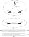
- FIG. 1 is a schematic diagram illustrating Mode 3 of embodiments of the present application.
- FIG. 2 is a schematic diagram illustrating Mode 4 of embodiments of the present application.
- transmission resources of vehicle-mounted terminals are allocated by base station 110, and the vehicle-mounted terminals transmit data on the sidelink based on the resources allocated by the base station 110.
- the base station 110 may allocate resources used for a single transmission to the terminals, and may also allocate resources for semi-static transmission to the terminals.
- the vehicle-mounted terminals adopt a transmission mode of sensing and reservation, and the vehicle-mounted terminal independently selects resources among the sidelink transmission resources for data transmission.
- the vehicle-mounted terminal 131 is described in detail as an example below.
- the vehicle-mounted terminal 131 obtains a set of available transmission resources in a resource pool by sensing, and the vehicle-mounted terminal 131 randomly selects a transmission resource from the set for data transmission.
- the vehicle-mounted terminal 131 may also adopt a semi-static transmission mode. That is, after acquiring a transmission resource, the vehicle-mounted terminal 131 continuously uses the transmission resource in multiple transmission periods to reduce resource reselection and the probability of resource conflict.
- the vehicle-mounted terminal 131 can carry information for reserving resources for the next transmission in the control information of current transmission, so that other terminals (for example, the vehicle-mounted terminal 132) can determine whether this resource is reserved and used by the user through detecting the control information of the user, thereby reducing resource conflicts.
- the vehicle-mounted terminal involved in the embodiments of the present application may be applicable to scenarios with high data interaction efficiency, such as autopilot.
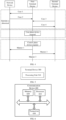
- FIG. 3 is a schematic flowchart of a wireless communication method 200 according to some embodiments of the present application.
- the method 200 may be executed by a first terminal device.
- the first terminal device shown in FIG. 3 may be the vehicle-mounted terminal shown in FIG. 1 or FIG. 2 .
- the method 200 may include some or all of the following contents:
- a first terminal device determines that an abnormality has occurred on the sidelink between the first terminal device and a second terminal device;
- the first terminal device responds to the abnormality of the sidelink.
- the sidelink between the first terminal device and the second terminal device may be a unicast link, and the sidelink between the first terminal device and the second terminal device may also be one of multicast links.
- the first terminal device may determine that an abnormality has occurred on the sidelink between the first terminal device and the second terminal device.
- a first message with respect to the sidelink is transmitted to a network device by the first terminal device, and a first timer expires.
- the first terminal device determines that an abnormality has occurred on the sidelink between the first terminal device and a second terminal device.
- the first timer is initiated when the first message is transmitted.
- the first timer can also be initiated at some other moments as long as abnormality judgment requirement of the sidelink is met.
- the first timer is stopped when a second message is received.
- a first duration is set for the first timer, after the first duration elapses since the timer is initiated, the first timer expires.
- the first terminal device senses the second message within the first duration.
- the first duration may be configured by the network device or pre-configured.
- the second message may be a response message to the first message, or some other messages.
- the first message is a sidelink user equipment message (SidelinkUEInformation).
- the second message is a radio resource control reconfiguration (RRCReconfiguration) message.
- RRCReconfiguration radio resource control reconfiguration
- the first terminal device determines that an abnormality has occurred on the sidelink between the first terminal device and the second terminal device.
- the third message is a configuration message, and when the third message indicates that an abnormality has occurred, it may mean that the first terminal device cannot perform configuration according to part or all of the content of the third message. That is, the abnormality of the sidelink may be an abnormality caused by the first terminal device.
- the third message is a configuration message, and when the third message indicates that an abnormality has occurred, it may mean that: the network device has not provided corresponding parameter configuration for the communication link between the first terminal device and the second terminal device.
- the third message is the RRCReconfiguration message.
- the first terminal device determines that an abnormality has occurred on the sidelink between the first terminal device and the second terminal device.
- the fourth message is a configuration message, and when the fourth message indicates that an abnormality has occurred, it may mean that the first terminal device cannot perform configuration according to part or all of the content of the fourth message. That is, the abnormality of the sidelink may be an abnormality caused by the first terminal device.
- the fourth message is a response message of the first configuration information transmitted to the second terminal device from the first terminal device.
- the fourth message indicates that an abnormality has occurred, it may mean that: the second terminal device cannot perform configuration according to part or all of contents of the first configuration information. That is, the abnormality of the sidelink may be an abnormality caused by the second terminal device.
- the first terminal device determines that an abnormality has occurred on the sidelink between the first terminal device and the second terminal device.
- the second timer is initiated when the fifth message is transmitted.
- the second timer can also be initiated at some other moments as long as the abnormality judgment requirement of the sidelink is met.
- the second timer is stopped when a sixth message is received.
- a second duration is set for the second timer, after the second duration elapses since the second timer is initiated, the second timer expires.
- the first terminal device senses the sixth message within the second duration.
- the second duration may be configured by the network device or pre-configured.
- the sixth message may be a response message to the fifth message, or some other messages.
- the fifth message is an access layer configuration message
- the fifth message is a message for requesting capability information of the second terminal device.
- the sixth message is an access layer configuration completion message, or the sixth message is a message used by the second terminal device for feeding back capability information.
- the first terminal device may determine that an abnormality has occurred on the sidelink between the first terminal device and the second terminal device.
- the first terminal device may determine that an abnormality has occurred on the sidelink between the first terminal device and the second terminal device.
- the first terminal device initiates the third timer according to at least one fourth indication information.
- the first terminal device initiates the third timer according to a first quantity of fourth indication information.
- the first quantity may be agreed upon by a protocol, or the first quantity is determined by the first terminal device, or the first quantity is configured or instructed by the network device.
- the fourth indication information is defined according to a physical feedback channel. For example, if no Hybrid Automatic Repeat reQuest (HARQ) feedback is received from the second terminal device, the bottom layer of the first terminal device triggers the generation of the fourth indication information and transfers the fourth indication information to the upper layer of the first terminal device.
- HARQ Hybrid Automatic Repeat reQuest
- the first terminal device stops the third timer according to at least one fifth indication information.
- the first terminal device stops the third timer according to a second quantity of the fifth indication information.
- the second quantity may be agreed upon by a protocol, or the second quantity is determined by the first terminal device, or the second quantity is configured or instructed by the network device.
- the fifth indication information is defined according to a physical feedback channel. For example, if the HARQ feedback from the second terminal device is received, the bottom layer of the first terminal device triggers the generation of the fifth indication information, and transfers the fifth indication information to the upper layer of the first terminal device.
- the fourth indication information and fifth indication information are defined based on the HARQ feedback message and/or the feedback channel.
- the fourth indication information or fifth indication information is defined according to the presence or absence of the HARQ feedback message.
- the fourth indication information or the fifth indication information is defined according to the signal quality (SINR, RSRP, RSRQ, etc.) of the HARQ feedback message.
- the fourth indication information or the fifth indication information is defined according to a combination of the presence or absence of the HARQ feedback message and the signal quality of the HARQ feedback message.
- the signal quality of the HARQ feedback message may include at least one of: signal to interference plus noise ratio (SINR), reference signal receiving power (RSRP), reference signal receiving quality (RSRQ).
- SINR signal to interference plus noise ratio
- RSRP reference signal receiving power
- RSSQ reference signal receiving quality
- the receiving device Since the time-frequency resources used by the transmitting end device is unpredictable to the receiving end device, the receiving device cannot distinguish whether it fails to receive information transmitted from the transmitting end device on such time-frequency resource due to an abnormal link, or whether the receiving end device has not transmitted information on such time-frequency resource. Therefore, in the above Case 5, since the resource location of the HARQ feedback message is known to both the transmitting end device (the first terminal device) and the receiving end device (the second terminal device), the problem of knowing no resources can be solved by restraining the third timer based on the HARQ feedback message, and it can also more conveniently determine whether the sidelink is abnormal.
- the first terminal device may determine that an abnormality has occurred on the sidelink between the first terminal device and the second terminal device.
- the first terminal device determines that an abnormality has occurred on the sidelink between the first terminal device and the second terminal device.
- the first terminal device modifies the first counter according to at least one sixth indication information.
- the present embodiment is configured to use the sixth indication information that reaches a certain quantity (that is, the first threshold) to trigger the abnormality judgment of the sidelink. Specifically, when the sixth indication information reaches a certain quantity, the first counter reaches the first threshold, and the first terminal device may determine that an abnormality has occurred on the sidelink between the first terminal device and the second terminal device.
- a certain quantity that is, the first threshold
- the sixth indication information is defined according to a physical feedback channel.
- the method further includes the following step.
- the first terminal device resets the first counter in response to the expiration of the fourth timer.
- the first counter can be reset when the fourth timer expires, so that the first counter restarts counting the sixth indication information. In this way, only relatively continuous pieces of sixth indication information are counted.
- the method further includes the following step.
- the fourth timer is initiated or reinitiated by the first terminal device according to at least one seventh indication information.
- the fourth timer is initiated or reinitiated every time the seventh indication information occurs to solve the problem that the interval between two adjacent seventh indication messages is too large.
- the fourth timer will expire, which resets the first counter, that is, restarts counting the seventh indication information, so that only relatively continuous pieces of seventh indication information are counted. In this way, the object of triggering the abnormality of the sidelink due to relatively continuous counts, that is, a certain amount of seventh indication information is achieved.
- the seventh indication information is defined according to a physical feedback channel.
- the first terminal device may specifically respond to the abnormality of the sidelink from a user plane perspective and/or a control plane perspective.
- the first terminal device responds to the abnormality of the sidelink from the perspective of the user plane, and/or the first terminal device responds to the abnormality of the sidelink from the perspective of the control plane.
- the order of the first terminal device's response to sidelink abnormality from the perspective of the user plane and the first terminal device's response to sidelink abnormality from the perspective of the control plane is not limited.
- the first terminal device may respond to the abnormality of the sidelink as follows:
- the bearer of the sidelink may be a signaling radio bearer (SRB) and/or a data radio bearer (DRB).
- SRB signaling radio bearer
- DRB data radio bearer
- the bearer(s) of the sidelink may refer to individual bearer or all bearers.
- the relevant entity of the bearer communicating through the sidelink may be individual entity.
- the relevant entity of the bearers communicated through the sidelink includes at least one of: a service data adaptation protocol (SDAP) entity, a packet data convergence protocol (PDCP) entity, a radio link control protocol (RLC) entity, and a media access control (MAC) layer entity.
- SDAP service data adaptation protocol
- PDCP packet data convergence protocol
- RLC radio link control protocol
- MAC media access control
- the first terminal device may respond to the abnormality of the sidelink in at least one of manners 1 to 3 described below, as shown in FIG. 4 .
- the first terminal device transmits the first indication information to the network device, and the first indication information is used for indicating that the sidelink related to the first terminal device is abnormal.
- the first indication information includes at least one of: application layer identify (ID), layer 2 ID, source address, destination address, quality of service (QoS) attribute, channel quality information, frequency point information, provider service identifier (PSID) information, PC5 QoS flow identifier (PFI) information or bearer information.
- ID application layer identify
- QoS quality of service
- PSID provider service identifier
- PFI PC5 QoS flow identifier
- the first indication information includes at least one of: type information of the abnormality of the sidelink related to the first terminal device, application layer ID, layer 2 ID, source address, destination address, QoS attribute, channel quality information, frequency point information, PSID information, PFI information or bearer information.
- the sidelink related to the first terminal device may be: part or all of the sidelink established with the first terminal device.
- sidelink 1 is established between the first terminal device and the second terminal device
- sidelink 2 is established between the first terminal device and the third terminal device
- sidelink 3 is established between the first terminal device and the fourth terminal device.
- the sidelink related to the first terminal device may be sidelink 1, sidelink 2, and sidelink 3.
- the sidelink related to the first terminal device may also be only sidelink 1 or only sidelink 2 or only sidelink 3.
- the type information of the abnormality of the sidelink related to the first terminal device may refer to:
- the type of the abnormality on the sidelink related to the first terminal device may be represented by a field, and different values in the field represent different types.
- timer may be used to record the abnormality generated on the sidelink during the capability transmission process, or the above timer may be used to record the abnormality generated on the sidelink during the access layer configuration process.
- the timer may be pre-configured or agreed upon by the protocol, or configured by the network device.
- the first terminal device may also transmit the fourth indication information to the network device, and the fourth indication information is used for indicating that the link between the first terminal device and the network device is abnormal, or the first terminal device, the fourth indication information is used for indicating reestablishing the link between the first terminal device and the network device
- the first terminal device transmits the second indication information to the second terminal device, and the second indication information is used for indicating that an abnormality has occurred on the sidelink related to the first terminal device, or the second indication information is used for indicating reestablishing the connection between the first terminal device and the second terminal device.
- the second indication information can be used to indicate that the connection between the first terminal device and the second terminal device needs to be reestablished, can also be used to indicate that the first terminal device is configured to reestablish the connection between the first terminal device and the second terminal device, and can also be used to indicate that the second terminal device is configured to reestablish the connection between the first terminal device and the second terminal device.
- the second indication information includes at least one of: application layer ID, layer 2 ID, source address, destination address, QoS attribute, channel quality information, frequency point information, PSID information, PFI information or bearer information.
- the second indication information includes at least one of: the type information of the abnormality generated on the sidelink related to the first terminal device, application layer ID, layer 2 ID, source address, destination address, QoS attribute, channel quality information, frequency point information, PSID information, PFI information or bearer information.
- the first terminal device transmits the third indication information to a higher layer, and the third indication information is used for indicating that an abnormality has occurred on the first terminal device.
- the upper layer may refer to the non-access layer.
- the third indication information includes at least one of: application layer ID, layer 2 ID, source address, destination address, QoS attribute, channel quality information, frequency point information, PSID information, PFI information, or bearer information.
- the third indication information includes at least one of: type information of the abnormality occurred on the sidelink related to the first terminal device, application layer ID, layer 2 ID, source address, destination address, and QoS attribute, channel quality information, frequency point information, PSID information, PFI information or bearer information.
- the layer 2 ID may be transmitted in the access layer such as the MAC layer and the physical layer.
- the source address may be the address of the first terminal device, and the destination address may be the address of the second terminal device.
- the bearer information may include bearer type and/or bearer ID.
- the bearer type can be DRB and SRB.
- the QoS attribute may include but is not limited to at least one of: PC5 5G QoS Indicator (PQI), data rate requirement, communication range, priority, delay requirements, packet error rate, maximum data burst volume.
- PQI PC5 5G QoS Indicator
- the network device is a network device serving the first terminal device.
- the first terminal device in response to determining by the first terminal device that the sidelink between it and the second terminal device is abnormal, responds to the abnormality of the sidelink, thereby improving the communication performance on the sidelink.
- FIG. 5 is a schematic block diagram illustrating a terminal device 300 according to embodiments of the present application.
- the terminal device 300 is the first terminal device, and includes: a processing unit 310, configured to: determine that abnormality has occurred on the sidelink between the first terminal device and the second terminal device; and respond to the abnormality of the sidelink.
- the processing unit 310 is further configured to:
- the relevant entity of the bearer communicating through the sidelink includes at least one of: a SDAP entity, a PDCP entity, a RLC entity, and a MAC layer entity.
- the terminal device 300 further includes: a communication unit 320, configured to transmit a first indication information to a network device, and the first indication information is used for indicating that abnormality has occurred on the sidelink related to the first terminal device.
- the first indication information includes at least one of: application layer ID, layer 2 ID, source address, destination address, QoS attribute, channel quality information, frequency point information, PSID information, PFI information, or bearer information.
- the first indication information includes at least one of: type information of the abnormality occurred on the sidelink related to the first terminal device, application layer ID, layer 2 ID, source address, destination address, QoS attribute, channel quality information, frequency point information, PSID information, PFI information or bearer information.
- the communication unit 320 is further configured to transmit a second indication information to the second terminal device, and the second indication information is used for indicating that abnormality has occurred on the sidelink related to the first terminal device.
- the second indication information is used for indicating reestablishment of a connection between the first terminal device and the second terminal device.
- the second indication information includes at least one of: application layer ID, layer 2 ID, source address, destination address, QoS Attribute, channel quality information, frequency point information, PSID information, PFI information or bearer information.
- the second indication information includes at least one of: the type information of the abnormality occurred on the sidelink related to the first terminal device, application layer ID, layer 2 ID, source address, destination address, QoS attribute, channel quality information, frequency point information, PSID information, PFI information or bearer information.
- the communication unit 320 is further configured to transmit a third indication information to a higher layer, and the third indication information is used for indicating that abnormality has occurred in the first terminal device.
- the third indication information includes at least one of: application layer ID, layer 2 ID, source address, destination address, QoS attribute, channel quality information, frequency point information, PSID information, PFI information, or bearer information.
- the third indication information includes at least one of: type information of the abnormality occurred on the sidelink related to the first terminal device, application layer ID, layer 2 ID, source address, destination address, QoS attribute, channel quality information, frequency point information, PSID information, PFI information or bearer information.
- the processing unit 310 is further configured to, in response to determining that the first terminal device transmits the first message with respect to the sidelink to the network device and the first timer expires, determine that abnormality has occurred on the sidelink between the first terminal device and the second terminal device.
- the first timer is initiated when a first message is transmitted.
- the first timer is stopped when a second message is received.
- the second message is an RRC reconfiguration message.
- the first message is the S idelinkUEInformation.
- the processing unit 310 is further configured to, in response to determining that the first terminal device receives a third message transmitted from the network device and/or the second terminal device and the third message indicates an abnormality has occurred, determine that an abnormality has occurred on the side link between the first terminal devices and the second terminal device.
- the third message is a configuration message, and when the third message indicates that an abnormality has occurred, it means that the first terminal device cannot perform configuration according to part or all of the content of the third message.
- the third message is a configuration message, and when the third message indicates that an abnormality has occurred, it may mean that: the network device has not provided corresponding parameter configuration for the communication link between the first terminal device and the second terminal device.
- the processing unit 310 is further configured to, in response to determining that the first terminal device receives a fourth message transmitted from the second terminal device and the fourth message indicates that an abnormality has occurred, determine that an abnormality has occurred on the sidelink between the first terminal devices and the second terminal device.
- the fourth message is a configuration message, and when the fourth message indicates that an abnormality has occurred, it means that the first terminal device cannot perform configuration according to part or all of the content of the fourth message.
- the fourth message is a response message of the first configuration information transmitted to the second terminal device from the first terminal device.
- the fourth message indicates that an abnormality has occurred, it means that: the second terminal device cannot perform configuration according to part or all of contents of the first configuration information.
- the processing unit 310 is further configured to, in response to determining that the first terminal device transmits a fifth message to the second terminal device and the second timer expires, determine that an abnormality has occurred on the sidelink between the first terminal device and the second terminal device.
- the second timer is initiated when the fifth message is transmitted.
- the second timer is stopped when a sixth message is received.
- the sixth message is an access layer configuration complete message, or the sixth message is a message about feedback capability information of the second terminal device.
- the fifth message is an access layer configuration complete message, or the fifth message is a message for requesting capability information of the second terminal device.
- the processing unit 310 is further configured to: when the third timer expires, determine that an abnormality has occurred on the sidelink between the first terminal device and the second terminal device.
- the processing unit 310 is further configured to start a third timer according to at least one fourth indication information.
- the fourth indication information is defined according to a physical feedback channel.
- the processing unit 310 is further configured to stop the third timer according to at least one fifth indication information.
- the fifth indication information is defined according to a physical feedback channel.
- the processing unit 310 is further configured to: in response to a first counter reaching a first threshold, determine that an abnormality has occurred on the sidelink between the first terminal device and the second terminal device.
- the processing unit 310 is further configured to modify the first counter according to at least one sixth indication information.
- the sixth indication information is defined according to a physical feedback channel.
- the processing unit 310 is further configured to reset the first counter when the fourth timer expires.
- the processing unit 310 is further configured to initiate or reinitiate the fourth timer according to at least one seventh indication information.
- the seventh indication information is defined according to a physical feedback channel.
- terminal device 400 may correspond to the first terminal device in the method embodiments of the present disclosure, and the above and other operations and/or functions of each unit in the terminal device 400 are to implement the corresponding process of the first terminal device in the method 200 shown in FIG. 4 , respectively.
- the terminal device 400 may correspond to the first terminal device in the method embodiments of the present disclosure, and the above and other operations and/or functions of each unit in the terminal device 400 are to implement the corresponding process of the first terminal device in the method 200 shown in FIG. 4 , respectively.
- the terminal device 400 may correspond to the first terminal device in the method embodiments of the present disclosure, and the above and other operations and/or functions of each unit in the terminal device 400 are to implement the corresponding process of the first terminal device in the method 200 shown in FIG. 4 , respectively.
- it is not repeated here.
- FIG. 6 is a schematic structural diagram illustrating a communication device 400 provided by embodiments of the present disclosure.
- the communication device 400 shown in FIG. 6 includes a processor 410.
- the processor 410 may call a computer program from a memory and run the computer program to implement the method provided in the embodiments of the present disclosure.
- the communication device 400 may further include a memory 420.
- the processor 410 may call the computer program from the memory 420 and run the computer program to implement the method provided in the embodiments of the present disclosure.
- the memory 420 may be separated from the processor 410, or may be integrated into the processor 410.
- the communication device 400 may further include a transceiver 430, and the processor 410 may control the transceiver 430 to communicate with other devices.
- the transceiver 430 may transmit information or data to other devices, or receive information or data transmitted from other devices.
- the transceiver 430 may include a transmitter and a receiver.
- the transceiver 430 may further include antennas, and the number of antennas may be one or more.
- the communication device 400 may be the network device of the embodiments of the present application, and may implement the corresponding process implemented by the network device in each method of the embodiments of the present application. For the sake of brevity, details are not repeated here.
- the communication device 400 may be the terminal device of the embodiments of the present application, and may implement the corresponding process implemented by the first terminal device in each method of the embodiments of the present application. For the sake of brevity, details are not repeated here..
- FIG. 7 is a schematic structural diagram of an apparatus provided by an embodiment of the present disclosure.
- the apparatus 500 shown in FIG. 7 includes a processor 510.
- the processor 510 may call a computer program from a memory and run the computer program to implement the method provided in the embodiments of the present disclosure.
- the apparatus 500 may further include a memory 520.
- the processor 510 may call the computer program from the memory 520 and run the computer program to implement the method provided in the embodiments of the present disclosure.
- the memory 520 may be separated from the processor 510, or may be integrated into the processor 510.
- the apparatus 500 may further include an input interface 530.
- the processor 510 can control the input interface 530 to communicate with other devices or chips, and specifically, can obtain information or data transmitted from other devices or chips.
- the apparatus 500 may further include an output interface 540.
- the processor 510 can control the output interface 540 to communicate with other devices or chips, and specifically, can output information or data to other devices or chips.
- the apparatus may be applied to the network device in the embodiments of the present disclosure, and may implement the corresponding process implemented by the network device in each method of the embodiments of the present disclosure. For the sake of brevity, details are not repeated here.
- the apparatus may be applied to the terminal device in the embodiments of the present disclosure, and may implement the corresponding process implemented by the first terminal device in each method of the embodiments of the present disclosure. For the sake of brevity, details are not repeated here.
- the apparatus mentioned in the embodiments of the present application may also be a chip.
- it can be a system-level chip, a system chip, a chip system, or a system-on-chip.
- FIG. 8 is a schematic block diagram illustrating a communication system 600 provided by embodiments of the present application. As shown in FIG. 8 , the communication system 600 includes a first terminal device 610, a network device 620, and a second terminal device 630.
- the first terminal device 610 may be used to implement the corresponding function implemented by the first terminal device in the foregoing method, and the network device 620 may be used to implement the corresponding function implemented by the network device in the foregoing method.
- the first terminal device 610 communicates with a second terminal device 630 through a sidelink.
- the second terminal device 630 can be used to implement the corresponding functions implemented by the second terminal device in the above method. For the sake of brevity, details are not repeated here.
- the processor of the embodiments of the present disclosure may be an integrated circuit chip with signal processing capability.
- the steps of the foregoing method embodiments can be performed by hardware integrated logic circuits in the processor or instructions in the form of software.
- the above-mentioned processor can be a general-purpose processor, a digital signal processor (DSP), an application specific integrated circuit (ASIC), a field programmable gate array (FPGA) or other programmable logic devices, discrete gates or transistor logic devices, discrete hardware components.
- DSP digital signal processor
- ASIC application specific integrated circuit
- FPGA field programmable gate array
- the methods, steps, and logical block diagrams disclosed in the embodiments of the present application can be implemented or executed.
- the general-purpose processor may be a microprocessor or the processor may also be any conventional processor or the like.
- the steps of the method disclosed in the embodiments of the present application can be directly executed by a hardware decoding processor, or executed by a combination of hardware and software modules in the decoding processor.
- the software module can be located in a mature storage medium in the field such as a random access memory, a flash memory, a read-only memory, a programmable read-only memory, or an electrically erasable programmable memory, registers.
- the storage medium is located in the memory, and the processor reads the information in the memory and completes the steps of the above method in combination with its hardware.
- the memory in the embodiments of the present disclosure may be volatile memory or non-volatile memory, or may include both volatile and non-volatile memory.
- the non-volatile memory can be read-only memory (ROM), programmable read-only memory (PROM), erasable programmable read-only memory (EPROM), and Electrically Erasable programmable read-only memory (EEPROM) or flash memory.
- ROM read-only memory
- PROM programmable read-only memory
- EPROM erasable programmable read-only memory
- EEPROM Electrically Erasable programmable read-only memory
- flash memory may be a random access memory (RAM), which is used as an external cache.
- RAM Direct Rambus RAM
- SRAM static random access memory
- DRAM dynamic random access memory
- SDRAM Synchronous DRAM
- DDR SDRAM Double Data Rate SDRAM
- ESDRAM Enhanced SDRAM
- SLDRAM Synchlink DRAM
- DR RAM Direct Rambus RAM
- the memory in the embodiments of the present disclosure may be a static RAM(SRAM), a dynamic RAM (DRAM), a Synchronous DRAM (SDRAM), a Double Data Rate SDRAM (DDR SDRAM), an Enhanced SDRAM (ESDRAM), a Synchlink DRAM (SLDRAM) and a Direct Rambus RAM (DR RAM) and so on.
- SRAM static RAM
- DRAM dynamic RAM
- SDRAM Synchronous DRAM
- DDR SDRAM Double Data Rate SDRAM
- ESDRAM Enhanced SDRAM
- SLDRAM Synchlink DRAM
- DR RAM Direct Rambus RAM
- the embodiments of the present disclosure further provide a computer readable storage medium for storing computer programs.
- the computer readable storage medium may be applied to the network device provided in the embodiments of the present disclosure, and the computer programs cause the computer to execute the corresponding process implemented by the network device in each method of the embodiments of the present disclosure. For brevity, details are not described herein again.
- the computer readable storage medium may be applied to the terminal device provided in the embodiments of the present disclosure, and the computer programs cause the computer to execute the corresponding process implemented by the first terminal device in each method of the embodiments of the present disclosure. For brevity, details are not described herein again.
- the embodiments of the present disclosure further provide a computer program product including computer programe instructions.
- the computer program product may be applied to the network device provided in the embodiments of the present disclosure, and the computer program instructions cause the computer to execute the corresponding process implemented by the network device in each method of the embodiments of the present disclosure.
- the computer program instructions cause the computer to execute the corresponding process implemented by the network device in each method of the embodiments of the present disclosure.
- the computer program product may be applied to the terminal device provided in the embodiments of the present disclosure, and the computer program instructions cause the computer to execute the corresponding process implemented by the first terminal device in each method of the embodiments of the present disclosure.
- the computer program instructions cause the computer to execute the corresponding process implemented by the first terminal device in each method of the embodiments of the present disclosure.
- the embodiments of the present application further provide a computer program.
- the computer program may be applied to the network device provided in the embodiments of the present disclosure, and the computer program, when run on a computer, causes the computer to execute the corresponding process implemented by the network device in each method of the embodiments of the present disclosure.
- the computer program when run on a computer, causes the computer to execute the corresponding process implemented by the network device in each method of the embodiments of the present disclosure.
- the computer program may be applied to the terminal device provided in the embodiments of the present disclosure, and the computer program, when run on a computer, causes the computer to execute the corresponding process implemented by the first terminal device in each method of the embodiments of the present disclosure.
- the computer program when run on a computer, causes the computer to execute the corresponding process implemented by the first terminal device in each method of the embodiments of the present disclosure.
- the proposed system, device, and method may be implemented in other ways.
- the device embodiments described above are merely illustrative.
- the division of the units is only a logical function division, and there may be other divisions in actual implementation, for example, multiple units or components may be combined or It can be integrated into another system, or some features can be ignored or not implemented.
- the displayed or discussed mutual coupling or direct coupling or communication connection may be indirect coupling or communication connection through some interfaces, devices or units, and may be in electrical, mechanical or other forms.
- the units described as separated components may or may not be physically separated, and the components displayed as units may or may not be physical units, that is, they may be located at one place, or they may be distributed on multiple network units. Some or all of the units may be selected according to actual needs to achieve the objectives of the solutions of the embodiments.
- the functional units in the various embodiments of the present disclosure may be integrated into one processing unit, or the units are separated physically, or two or more units may be integrated into one unit.
- the function is implemented in the form of a software functional unit and sold or used as an independent product, it can be stored in a computer readable storage medium.
- the part of the technical solution of this application in essence or that contributes to the prior art or the part of the technical solution can be embodied in the form of a software product, and the computer software product is stored in a storage medium.
- the storage medium includes several instructions so that a computer (which may be a personal computer, a server, or a network device, etc.) executes all or part of the steps of the methods described in the various embodiments of the present disclosure.
- the aforementioned storage medium includes: U disk, mobile hard disk drive, Read-Only Memory (ROM), Random Access Memory (RAM), magnetic disks or optical disks and other media that can store program codes.
Landscapes
- Engineering & Computer Science (AREA)
- Computer Networks & Wireless Communication (AREA)
- Signal Processing (AREA)
- Mobile Radio Communication Systems (AREA)
- Telephone Function (AREA)
Priority Applications (1)
| Application Number | Priority Date | Filing Date | Title |
|---|---|---|---|
| EP23192155.2A EP4250862A3 (en) | 2019-06-26 | 2020-02-05 | Wireless communication method and terminal device |
Applications Claiming Priority (4)
| Application Number | Priority Date | Filing Date | Title |
|---|---|---|---|
| PCT/CN2019/093129 WO2020258107A1 (zh) | 2019-06-26 | 2019-06-26 | 无线通信方法和终端设备 |
| PCT/CN2019/105177 WO2020258521A1 (zh) | 2019-06-26 | 2019-09-10 | 无线通信方法和终端设备 |
| PCT/CN2019/115155 WO2020258632A1 (zh) | 2019-06-26 | 2019-11-01 | 无线通信方法和终端设备 |
| PCT/CN2020/074367 WO2020258885A1 (zh) | 2019-06-26 | 2020-02-05 | 无线通信方法和终端设备 |
Related Child Applications (2)
| Application Number | Title | Priority Date | Filing Date |
|---|---|---|---|
| EP23192155.2A Division EP4250862A3 (en) | 2019-06-26 | 2020-02-05 | Wireless communication method and terminal device |
| EP23192155.2A Division-Into EP4250862A3 (en) | 2019-06-26 | 2020-02-05 | Wireless communication method and terminal device |
Publications (3)
| Publication Number | Publication Date |
|---|---|
| EP3975645A1 EP3975645A1 (en) | 2022-03-30 |
| EP3975645A4 EP3975645A4 (en) | 2022-08-03 |
| EP3975645B1 true EP3975645B1 (en) | 2023-09-27 |
Family
ID=74060714
Family Applications (2)
| Application Number | Title | Priority Date | Filing Date |
|---|---|---|---|
| EP20831270.2A Active EP3975645B1 (en) | 2019-06-26 | 2020-02-05 | Wireless communication method and terminal device |
| EP23192155.2A Pending EP4250862A3 (en) | 2019-06-26 | 2020-02-05 | Wireless communication method and terminal device |
Family Applications After (1)
| Application Number | Title | Priority Date | Filing Date |
|---|---|---|---|
| EP23192155.2A Pending EP4250862A3 (en) | 2019-06-26 | 2020-02-05 | Wireless communication method and terminal device |
Country Status (8)
| Country | Link |
|---|---|
| US (2) | US12323828B2 (https=) |
| EP (2) | EP3975645B1 (https=) |
| JP (1) | JP7457735B2 (https=) |
| KR (1) | KR20220024164A (https=) |
| CN (1) | CN114125914B (https=) |
| ES (1) | ES2965846T3 (https=) |
| FI (1) | FI3975645T3 (https=) |
| WO (2) | WO2020258632A1 (https=) |
Families Citing this family (3)
| Publication number | Priority date | Publication date | Assignee | Title |
|---|---|---|---|---|
| CN118764980A (zh) * | 2019-02-12 | 2024-10-11 | 交互数字专利控股公司 | 无线发送/接收单元、由其实施的方法和检测sl-rlf的方法 |
| WO2021190504A1 (en) * | 2020-03-25 | 2021-09-30 | Telefonaktiebolaget Lm Ericsson (Publ) | Methods, apparatuses and computer-readable medium for device-to-device communication |
| EP4351187A1 (en) * | 2022-10-03 | 2024-04-10 | Nokia Technologies Oy | U2u relay ue-initiated dedicated relay discovery for supporting direct-to-indirect path switch |
Family Cites Families (22)
| Publication number | Priority date | Publication date | Assignee | Title |
|---|---|---|---|---|
| US7873710B2 (en) * | 2007-02-06 | 2011-01-18 | 5O9, Inc. | Contextual data communication platform |
| CN103037359A (zh) | 2011-09-30 | 2013-04-10 | 华为技术有限公司 | 一种实现设备到设备的通讯方法、终端及系统 |
| US9265071B2 (en) | 2012-07-10 | 2016-02-16 | Electronics And Telecommunications Research Institute | Signalling method for direct communication between terminals |
| WO2014104627A1 (ko) | 2012-12-30 | 2014-07-03 | 엘지전자 주식회사 | 무선 통신 시스템에서 장치 대 장치 통신 수행 방법 및 장치 |
| CN104540159A (zh) * | 2015-01-30 | 2015-04-22 | 深圳酷派技术有限公司 | 汇报方法、汇报系统、资源配置方法和系统 |
| CN105992364B (zh) * | 2015-03-02 | 2019-06-11 | 中兴通讯股份有限公司 | 资源处理方法及装置 |
| CN107771410B (zh) * | 2015-05-26 | 2021-03-19 | Lg 电子株式会社 | 在无线通信系统中通过ue实现的解除链接方法和使用所述方法的ue |
| DE102015218800A1 (de) * | 2015-09-29 | 2017-03-30 | Continental Automotive Gmbh | Kommunikationssystem zur V2X-Kommunikation |
| CN105611642A (zh) | 2016-01-08 | 2016-05-25 | 宇龙计算机通信科技(深圳)有限公司 | 一种数据传输的配置方法、基站和用户设备 |
| CN105704812B (zh) * | 2016-01-15 | 2019-04-19 | 宇龙计算机通信科技(深圳)有限公司 | 一种v2x业务上行控制面信令处理方法、装置及终端 |
| US10735926B2 (en) * | 2016-02-11 | 2020-08-04 | Lg Electronics Inc. | Method for operating terminal in wireless communication system and terminal using the same |
| EP4586721A3 (en) * | 2016-03-30 | 2025-10-08 | InterDigital Patent Holdings, Inc. | Methods and systems for scheduling in uu-based vehicle-to-vehicle communication |
| US10433342B2 (en) * | 2016-10-19 | 2019-10-01 | Qualcomm Incorporated | Enhanced random access channel (RACH) procedure |
| US10397836B2 (en) * | 2016-10-27 | 2019-08-27 | Ofinno, Llc | Handover for UE with V2X service |
| WO2018232108A1 (en) * | 2017-06-16 | 2018-12-20 | Intel Corporation | L2 handling for bearer type change |
| CN109309928B (zh) | 2017-07-26 | 2021-01-29 | 华为技术有限公司 | D2d链路检测方法、相关装置及系统 |
| CN109474937A (zh) * | 2017-09-08 | 2019-03-15 | 索尼公司 | 无线通信方法和无线通信设备 |
| WO2019084816A1 (zh) * | 2017-10-31 | 2019-05-09 | Oppo广东移动通信有限公司 | 一种终端选择资源的方法及装置、计算机存储介质 |
| CN109565833B (zh) * | 2017-11-28 | 2021-04-16 | Oppo广东移动通信有限公司 | 分配功率的方法和设备 |
| WO2020107410A1 (zh) * | 2018-11-30 | 2020-06-04 | 北京小米移动软件有限公司 | 调度侧链路资源的请求方法、装置及存储介质 |
| US11910457B2 (en) * | 2019-01-31 | 2024-02-20 | Apple Inc. | Unicast sidelink access stratum level connection maintenance |
| US12016076B2 (en) * | 2019-06-21 | 2024-06-18 | Beijing Xiaomi Mobile Software Co., Ltd. | Information processing method and apparatus, and computer storage medium |
-
2019
- 2019-11-01 WO PCT/CN2019/115155 patent/WO2020258632A1/zh not_active Ceased
-
2020
- 2020-02-05 CN CN202111436158.XA patent/CN114125914B/zh active Active
- 2020-02-05 FI FIEP20831270.2T patent/FI3975645T3/fi active
- 2020-02-05 EP EP20831270.2A patent/EP3975645B1/en active Active
- 2020-02-05 ES ES20831270T patent/ES2965846T3/es active Active
- 2020-02-05 KR KR1020217042151A patent/KR20220024164A/ko active Pending
- 2020-02-05 WO PCT/CN2020/074367 patent/WO2020258885A1/zh not_active Ceased
- 2020-02-05 EP EP23192155.2A patent/EP4250862A3/en active Pending
- 2020-02-05 JP JP2021577175A patent/JP7457735B2/ja active Active
-
2021
- 2021-12-17 US US17/554,188 patent/US12323828B2/en active Active
-
2025
- 2025-04-29 US US19/192,722 patent/US20250261006A1/en active Pending
Also Published As
| Publication number | Publication date |
|---|---|
| US20250261006A1 (en) | 2025-08-14 |
| WO2020258885A1 (zh) | 2020-12-30 |
| FI3975645T3 (fi) | 2023-11-27 |
| JP2022539127A (ja) | 2022-09-07 |
| WO2020258632A1 (zh) | 2020-12-30 |
| CN114125914A (zh) | 2022-03-01 |
| EP4250862A3 (en) | 2023-12-27 |
| ES2965846T3 (es) | 2024-04-17 |
| JP7457735B2 (ja) | 2024-03-28 |
| KR20220024164A (ko) | 2022-03-03 |
| US12323828B2 (en) | 2025-06-03 |
| CN114125914B (zh) | 2023-11-17 |
| US20220110010A1 (en) | 2022-04-07 |
| EP3975645A1 (en) | 2022-03-30 |
| EP4250862A2 (en) | 2023-09-27 |
| EP3975645A4 (en) | 2022-08-03 |
Similar Documents
| Publication | Publication Date | Title |
|---|---|---|
| US11317389B2 (en) | Data transmission method, apparatus, and system | |
| US20250261006A1 (en) | Wireless communication method and terminal device | |
| JP2024532443A (ja) | サイドリンク通信方法および装置 | |
| EP3793296B1 (en) | Communication method and device | |
| CN114731632B (zh) | 一种随机接入的方法和装置 | |
| TW201916706A (zh) | 用於資源選擇的方法和設備 | |
| JP6726767B2 (ja) | ページング検出ウィンドウ | |
| EP3941150B1 (en) | Random access method, terminal device and network device | |
| WO2017049595A1 (zh) | 边链路信息传输装置、方法以及通信系统 | |
| CN113647182B (zh) | 无线通信的方法和设备 | |
| CN103118417A (zh) | 信息传输方法和用户设备 | |
| WO2021217363A1 (zh) | 无线通信方法、终端设备和网络设备 | |
| CN113647171A (zh) | 无线通信的方法和设备 | |
| KR20240005079A (ko) | 연결 실패 검출 방법 및 장치, 통신 디바이스 및 저장 매체(connection failure detection method and apparatus, communication device, and storage medium) | |
| CN113938942B (zh) | 侧行链路监测的方法和设备 | |
| WO2020124534A1 (zh) | 数据传输的方法和设备 | |
| WO2022218416A1 (zh) | 一种反馈方法、装置及设备 | |
| WO2020258521A1 (zh) | 无线通信方法和终端设备 | |
| JP7672577B2 (ja) | サイドリンク通信を管理するための技術 | |
| WO2021028051A1 (en) | Methods, apparatus, and computer programs | |
| WO2025010660A1 (zh) | 一种无线资源管理方法、装置、终端、芯片和存储介质 | |
| US20250185064A1 (en) | Communication method, apparatus, and system | |
| CN119450735A (zh) | 载波处理方法、终端设备及存储介质 | |
| CN118104359A (zh) | 消息传输方法、相关设备及介质 | |
| CN118510013A (zh) | 一种配置参数的通信方法、通信装置和通信系统 |
Legal Events
| Date | Code | Title | Description |
|---|---|---|---|
| STAA | Information on the status of an ep patent application or granted ep patent |
Free format text: STATUS: THE INTERNATIONAL PUBLICATION HAS BEEN MADE |
|
| PUAI | Public reference made under article 153(3) epc to a published international application that has entered the european phase |
Free format text: ORIGINAL CODE: 0009012 |
|
| STAA | Information on the status of an ep patent application or granted ep patent |
Free format text: STATUS: REQUEST FOR EXAMINATION WAS MADE |
|
| 17P | Request for examination filed |
Effective date: 20211220 |
|
| AK | Designated contracting states |
Kind code of ref document: A1 Designated state(s): AL AT BE BG CH CY CZ DE DK EE ES FI FR GB GR HR HU IE IS IT LI LT LU LV MC MK MT NL NO PL PT RO RS SE SI SK SM TR |
|
| A4 | Supplementary search report drawn up and despatched |
Effective date: 20220630 |
|
| RIC1 | Information provided on ipc code assigned before grant |
Ipc: H04W 76/14 20180101ALN20220624BHEP Ipc: H04W 76/34 20180101ALI20220624BHEP Ipc: H04W 76/19 20180101AFI20220624BHEP |
|
| DAV | Request for validation of the european patent (deleted) | ||
| DAX | Request for extension of the european patent (deleted) | ||
| REG | Reference to a national code |
Ref country code: DE Free format text: PREVIOUS MAIN CLASS: H04W0072040000 Ipc: H04W0076190000 Ref country code: DE Ref legal event code: R079 Ref document number: 602020018426 Country of ref document: DE Free format text: PREVIOUS MAIN CLASS: H04W0072040000 Ipc: H04W0076190000 |
|
| GRAP | Despatch of communication of intention to grant a patent |
Free format text: ORIGINAL CODE: EPIDOSNIGR1 |
|
| STAA | Information on the status of an ep patent application or granted ep patent |
Free format text: STATUS: GRANT OF PATENT IS INTENDED |
|
| RIC1 | Information provided on ipc code assigned before grant |
Ipc: H04W 76/14 20180101ALN20230322BHEP Ipc: H04W 76/34 20180101ALI20230322BHEP Ipc: H04W 76/19 20180101AFI20230322BHEP |
|
| INTG | Intention to grant announced |
Effective date: 20230411 |
|
| GRAS | Grant fee paid |
Free format text: ORIGINAL CODE: EPIDOSNIGR3 |
|
| GRAA | (expected) grant |
Free format text: ORIGINAL CODE: 0009210 |
|
| STAA | Information on the status of an ep patent application or granted ep patent |
Free format text: STATUS: THE PATENT HAS BEEN GRANTED |
|
| AK | Designated contracting states |
Kind code of ref document: B1 Designated state(s): AL AT BE BG CH CY CZ DE DK EE ES FI FR GB GR HR HU IE IS IT LI LT LU LV MC MK MT NL NO PL PT RO RS SE SI SK SM TR |
|
| REG | Reference to a national code |
Ref country code: GB Ref legal event code: FG4D |
|
| REG | Reference to a national code |
Ref country code: CH Ref legal event code: EP |
|
| REG | Reference to a national code |
Ref country code: DE Ref legal event code: R096 Ref document number: 602020018426 Country of ref document: DE |
|
| REG | Reference to a national code |
Ref country code: IE Ref legal event code: FG4D |
|
| REG | Reference to a national code |
Ref country code: FI Ref legal event code: FGE |
|
| REG | Reference to a national code |
Ref country code: NL Ref legal event code: FP |
|
| REG | Reference to a national code |
Ref country code: SE Ref legal event code: TRGR |
|
| REG | Reference to a national code |
Ref country code: LT Ref legal event code: MG9D |
|
| PG25 | Lapsed in a contracting state [announced via postgrant information from national office to epo] |
Ref country code: GR Free format text: LAPSE BECAUSE OF FAILURE TO SUBMIT A TRANSLATION OF THE DESCRIPTION OR TO PAY THE FEE WITHIN THE PRESCRIBED TIME-LIMIT Effective date: 20231228 |
|
| PG25 | Lapsed in a contracting state [announced via postgrant information from national office to epo] |
Ref country code: RS Free format text: LAPSE BECAUSE OF FAILURE TO SUBMIT A TRANSLATION OF THE DESCRIPTION OR TO PAY THE FEE WITHIN THE PRESCRIBED TIME-LIMIT Effective date: 20230927 Ref country code: NO Free format text: LAPSE BECAUSE OF FAILURE TO SUBMIT A TRANSLATION OF THE DESCRIPTION OR TO PAY THE FEE WITHIN THE PRESCRIBED TIME-LIMIT Effective date: 20231227 Ref country code: LV Free format text: LAPSE BECAUSE OF FAILURE TO SUBMIT A TRANSLATION OF THE DESCRIPTION OR TO PAY THE FEE WITHIN THE PRESCRIBED TIME-LIMIT Effective date: 20230927 Ref country code: LT Free format text: LAPSE BECAUSE OF FAILURE TO SUBMIT A TRANSLATION OF THE DESCRIPTION OR TO PAY THE FEE WITHIN THE PRESCRIBED TIME-LIMIT Effective date: 20230927 Ref country code: HR Free format text: LAPSE BECAUSE OF FAILURE TO SUBMIT A TRANSLATION OF THE DESCRIPTION OR TO PAY THE FEE WITHIN THE PRESCRIBED TIME-LIMIT Effective date: 20230927 Ref country code: GR Free format text: LAPSE BECAUSE OF FAILURE TO SUBMIT A TRANSLATION OF THE DESCRIPTION OR TO PAY THE FEE WITHIN THE PRESCRIBED TIME-LIMIT Effective date: 20231228 |
|
| P01 | Opt-out of the competence of the unified patent court (upc) registered |
Effective date: 20240110 |
|
| REG | Reference to a national code |
Ref country code: AT Ref legal event code: MK05 Ref document number: 1616647 Country of ref document: AT Kind code of ref document: T Effective date: 20230927 |
|
| PG25 | Lapsed in a contracting state [announced via postgrant information from national office to epo] |
Ref country code: IS Free format text: LAPSE BECAUSE OF FAILURE TO SUBMIT A TRANSLATION OF THE DESCRIPTION OR TO PAY THE FEE WITHIN THE PRESCRIBED TIME-LIMIT Effective date: 20240127 |
|
| REG | Reference to a national code |
Ref country code: ES Ref legal event code: FG2A Ref document number: 2965846 Country of ref document: ES Kind code of ref document: T3 Effective date: 20240417 |
|
| PG25 | Lapsed in a contracting state [announced via postgrant information from national office to epo] |
Ref country code: AT Free format text: LAPSE BECAUSE OF FAILURE TO SUBMIT A TRANSLATION OF THE DESCRIPTION OR TO PAY THE FEE WITHIN THE PRESCRIBED TIME-LIMIT Effective date: 20230927 |
|
| PG25 | Lapsed in a contracting state [announced via postgrant information from national office to epo] |
Ref country code: SM Free format text: LAPSE BECAUSE OF FAILURE TO SUBMIT A TRANSLATION OF THE DESCRIPTION OR TO PAY THE FEE WITHIN THE PRESCRIBED TIME-LIMIT Effective date: 20230927 Ref country code: RO Free format text: LAPSE BECAUSE OF FAILURE TO SUBMIT A TRANSLATION OF THE DESCRIPTION OR TO PAY THE FEE WITHIN THE PRESCRIBED TIME-LIMIT Effective date: 20230927 Ref country code: IS Free format text: LAPSE BECAUSE OF FAILURE TO SUBMIT A TRANSLATION OF THE DESCRIPTION OR TO PAY THE FEE WITHIN THE PRESCRIBED TIME-LIMIT Effective date: 20240127 Ref country code: EE Free format text: LAPSE BECAUSE OF FAILURE TO SUBMIT A TRANSLATION OF THE DESCRIPTION OR TO PAY THE FEE WITHIN THE PRESCRIBED TIME-LIMIT Effective date: 20230927 Ref country code: CZ Free format text: LAPSE BECAUSE OF FAILURE TO SUBMIT A TRANSLATION OF THE DESCRIPTION OR TO PAY THE FEE WITHIN THE PRESCRIBED TIME-LIMIT Effective date: 20230927 Ref country code: AT Free format text: LAPSE BECAUSE OF FAILURE TO SUBMIT A TRANSLATION OF THE DESCRIPTION OR TO PAY THE FEE WITHIN THE PRESCRIBED TIME-LIMIT Effective date: 20230927 Ref country code: PT Free format text: LAPSE BECAUSE OF FAILURE TO SUBMIT A TRANSLATION OF THE DESCRIPTION OR TO PAY THE FEE WITHIN THE PRESCRIBED TIME-LIMIT Effective date: 20240129 Ref country code: SK Free format text: LAPSE BECAUSE OF FAILURE TO SUBMIT A TRANSLATION OF THE DESCRIPTION OR TO PAY THE FEE WITHIN THE PRESCRIBED TIME-LIMIT Effective date: 20230927 |
|
| PG25 | Lapsed in a contracting state [announced via postgrant information from national office to epo] |
Ref country code: PL Free format text: LAPSE BECAUSE OF FAILURE TO SUBMIT A TRANSLATION OF THE DESCRIPTION OR TO PAY THE FEE WITHIN THE PRESCRIBED TIME-LIMIT Effective date: 20230927 |
|
| REG | Reference to a national code |
Ref country code: DE Ref legal event code: R097 Ref document number: 602020018426 Country of ref document: DE |
|
| PG25 | Lapsed in a contracting state [announced via postgrant information from national office to epo] |
Ref country code: DK Free format text: LAPSE BECAUSE OF FAILURE TO SUBMIT A TRANSLATION OF THE DESCRIPTION OR TO PAY THE FEE WITHIN THE PRESCRIBED TIME-LIMIT Effective date: 20230927 |
|
| PG25 | Lapsed in a contracting state [announced via postgrant information from national office to epo] |
Ref country code: DK Free format text: LAPSE BECAUSE OF FAILURE TO SUBMIT A TRANSLATION OF THE DESCRIPTION OR TO PAY THE FEE WITHIN THE PRESCRIBED TIME-LIMIT Effective date: 20230927 |
|
| PLBE | No opposition filed within time limit |
Free format text: ORIGINAL CODE: 0009261 |
|
| STAA | Information on the status of an ep patent application or granted ep patent |
Free format text: STATUS: NO OPPOSITION FILED WITHIN TIME LIMIT |
|
| 26N | No opposition filed |
Effective date: 20240628 |
|
| PG25 | Lapsed in a contracting state [announced via postgrant information from national office to epo] |
Ref country code: MC Free format text: LAPSE BECAUSE OF FAILURE TO SUBMIT A TRANSLATION OF THE DESCRIPTION OR TO PAY THE FEE WITHIN THE PRESCRIBED TIME-LIMIT Effective date: 20230927 |
|
| PG25 | Lapsed in a contracting state [announced via postgrant information from national office to epo] |
Ref country code: LU Free format text: LAPSE BECAUSE OF NON-PAYMENT OF DUE FEES Effective date: 20240205 |
|
| PG25 | Lapsed in a contracting state [announced via postgrant information from national office to epo] |
Ref country code: SI Free format text: LAPSE BECAUSE OF FAILURE TO SUBMIT A TRANSLATION OF THE DESCRIPTION OR TO PAY THE FEE WITHIN THE PRESCRIBED TIME-LIMIT Effective date: 20230927 |
|
| PG25 | Lapsed in a contracting state [announced via postgrant information from national office to epo] |
Ref country code: SI Free format text: LAPSE BECAUSE OF FAILURE TO SUBMIT A TRANSLATION OF THE DESCRIPTION OR TO PAY THE FEE WITHIN THE PRESCRIBED TIME-LIMIT Effective date: 20230927 Ref country code: LU Free format text: LAPSE BECAUSE OF NON-PAYMENT OF DUE FEES Effective date: 20240205 |
|
| PG25 | Lapsed in a contracting state [announced via postgrant information from national office to epo] |
Ref country code: BG Free format text: LAPSE BECAUSE OF FAILURE TO SUBMIT A TRANSLATION OF THE DESCRIPTION OR TO PAY THE FEE WITHIN THE PRESCRIBED TIME-LIMIT Effective date: 20230927 |
|
| PG25 | Lapsed in a contracting state [announced via postgrant information from national office to epo] |
Ref country code: BG Free format text: LAPSE BECAUSE OF FAILURE TO SUBMIT A TRANSLATION OF THE DESCRIPTION OR TO PAY THE FEE WITHIN THE PRESCRIBED TIME-LIMIT Effective date: 20230927 |
|
| PG25 | Lapsed in a contracting state [announced via postgrant information from national office to epo] |
Ref country code: IE Free format text: LAPSE BECAUSE OF NON-PAYMENT OF DUE FEES Effective date: 20240205 |
|
| PG25 | Lapsed in a contracting state [announced via postgrant information from national office to epo] |
Ref country code: IE Free format text: LAPSE BECAUSE OF NON-PAYMENT OF DUE FEES Effective date: 20240205 |
|
| PG25 | Lapsed in a contracting state [announced via postgrant information from national office to epo] |
Ref country code: CY Free format text: LAPSE BECAUSE OF FAILURE TO SUBMIT A TRANSLATION OF THE DESCRIPTION OR TO PAY THE FEE WITHIN THE PRESCRIBED TIME-LIMIT; INVALID AB INITIO Effective date: 20200205 |
|
| PG25 | Lapsed in a contracting state [announced via postgrant information from national office to epo] |
Ref country code: HU Free format text: LAPSE BECAUSE OF FAILURE TO SUBMIT A TRANSLATION OF THE DESCRIPTION OR TO PAY THE FEE WITHIN THE PRESCRIBED TIME-LIMIT; INVALID AB INITIO Effective date: 20200205 |
|
| PG25 | Lapsed in a contracting state [announced via postgrant information from national office to epo] |
Ref country code: TR Free format text: LAPSE BECAUSE OF FAILURE TO SUBMIT A TRANSLATION OF THE DESCRIPTION OR TO PAY THE FEE WITHIN THE PRESCRIBED TIME-LIMIT Effective date: 20230927 |
|
| PGFP | Annual fee paid to national office [announced via postgrant information from national office to epo] |
Ref country code: GB Payment date: 20251218 Year of fee payment: 7 |
|
| PGFP | Annual fee paid to national office [announced via postgrant information from national office to epo] |
Ref country code: FI Payment date: 20251230 Year of fee payment: 7 |
|
| PGFP | Annual fee paid to national office [announced via postgrant information from national office to epo] |
Ref country code: NL Payment date: 20251225 Year of fee payment: 7 Ref country code: FR Payment date: 20251222 Year of fee payment: 7 |
|
| REG | Reference to a national code |
Ref country code: CH Ref legal event code: U11 Free format text: ST27 STATUS EVENT CODE: U-0-0-U10-U11 (AS PROVIDED BY THE NATIONAL OFFICE) Effective date: 20260301 |
|
| PGFP | Annual fee paid to national office [announced via postgrant information from national office to epo] |
Ref country code: SE Payment date: 20251230 Year of fee payment: 7 |
|
| PGFP | Annual fee paid to national office [announced via postgrant information from national office to epo] |
Ref country code: ES Payment date: 20260311 Year of fee payment: 7 |
|
| PGFP | Annual fee paid to national office [announced via postgrant information from national office to epo] |
Ref country code: DE Payment date: 20251224 Year of fee payment: 7 |
|
| PGFP | Annual fee paid to national office [announced via postgrant information from national office to epo] |
Ref country code: BE Payment date: 20260105 Year of fee payment: 7 Ref country code: IT Payment date: 20260122 Year of fee payment: 7 |
|
| PGFP | Annual fee paid to national office [announced via postgrant information from national office to epo] |
Ref country code: CH Payment date: 20260301 Year of fee payment: 7 |