EP3974606A1 - Verriegelungsvorrichtung, schlossanordnung und kraftfahrzeug - Google Patents
Verriegelungsvorrichtung, schlossanordnung und kraftfahrzeug Download PDFInfo
- Publication number
- EP3974606A1 EP3974606A1 EP21176406.3A EP21176406A EP3974606A1 EP 3974606 A1 EP3974606 A1 EP 3974606A1 EP 21176406 A EP21176406 A EP 21176406A EP 3974606 A1 EP3974606 A1 EP 3974606A1
- Authority
- EP
- European Patent Office
- Prior art keywords
- locking device
- lock
- cylinder shaft
- lock cylinder
- positioning arrangement
- Prior art date
- Legal status (The legal status is an assumption and is not a legal conclusion. Google has not performed a legal analysis and makes no representation as to the accuracy of the status listed.)
- Granted
Links
Images
Classifications
-
- E—FIXED CONSTRUCTIONS
- E05—LOCKS; KEYS; WINDOW OR DOOR FITTINGS; SAFES
- E05B—LOCKS; ACCESSORIES THEREFOR; HANDCUFFS
- E05B85/00—Details of vehicle locks not provided for in groups E05B77/00 - E05B83/00
- E05B85/06—Lock cylinder arrangements
-
- E—FIXED CONSTRUCTIONS
- E05—LOCKS; KEYS; WINDOW OR DOOR FITTINGS; SAFES
- E05B—LOCKS; ACCESSORIES THEREFOR; HANDCUFFS
- E05B17/00—Accessories in connection with locks
- E05B17/0054—Fraction or shear lines; Slip-clutches, resilient parts or the like for preventing damage when forced or slammed
- E05B17/0058—Fraction or shear lines; Slip-clutches, resilient parts or the like for preventing damage when forced or slammed with non-destructive disengagement
-
- E—FIXED CONSTRUCTIONS
- E05—LOCKS; KEYS; WINDOW OR DOOR FITTINGS; SAFES
- E05B—LOCKS; ACCESSORIES THEREFOR; HANDCUFFS
- E05B17/00—Accessories in connection with locks
- E05B17/0054—Fraction or shear lines; Slip-clutches, resilient parts or the like for preventing damage when forced or slammed
- E05B17/0062—Fraction or shear lines; Slip-clutches, resilient parts or the like for preventing damage when forced or slammed with destructive disengagement
-
- E—FIXED CONSTRUCTIONS
- E05—LOCKS; KEYS; WINDOW OR DOOR FITTINGS; SAFES
- E05B—LOCKS; ACCESSORIES THEREFOR; HANDCUFFS
- E05B17/00—Accessories in connection with locks
- E05B17/04—Devices for coupling the turning cylinder of a single or a double cylinder lock with the bolt operating member
- E05B17/041—Coupling device with a shaft projecting axially rearwardly from the cylinder, e.g. affording a degree of universal motion to compensate for misalignment
-
- E—FIXED CONSTRUCTIONS
- E05—LOCKS; KEYS; WINDOW OR DOOR FITTINGS; SAFES
- E05B—LOCKS; ACCESSORIES THEREFOR; HANDCUFFS
- E05B77/00—Vehicle locks characterised by special functions or purposes
- E05B77/44—Burglar prevention, e.g. protecting against opening by unauthorised tools
-
- E—FIXED CONSTRUCTIONS
- E05—LOCKS; KEYS; WINDOW OR DOOR FITTINGS; SAFES
- E05B—LOCKS; ACCESSORIES THEREFOR; HANDCUFFS
- E05B79/00—Mounting or connecting vehicle locks or parts thereof
- E05B79/10—Connections between movable lock parts
- E05B79/12—Connections between movable lock parts using connecting rods
- E05B79/18—Rod guides
Definitions
- the invention relates to a locking device, in particular a locking device, in particular for a motor vehicle, and to a lock arrangement. Another aspect of the invention relates to a motor vehicle that has a locking device.
- Locking devices are, for example, from DE 10 2009 044 598 A1 famous. Locking devices described in said document include a support housing in which a cylinder core is rotatably accommodated. A lock cylinder shaft couples the cylinder core to a lock spaced from the cylinder core.
- a problem with mechanical locking devices of the type mentioned is that they are inherently susceptible to mechanical attacks.
- the door lock can be opened by coupling a tool to the lock cylinder shaft and forcibly rotating the lock cylinder shaft.
- this forced opening is usually associated with damage to the locking device and/or its surroundings, it can result in successful unauthorized entry, which is of course undesirable.
- the task is to provide a structurally elegant development of a locking device that is equipped with effective protective measures against mechanical attacks, for example of the type described.
- the object is achieved with a locking device according to claim 1.
- the object is also achieved with a lock arrangement having the features of claim 17 and with a motor vehicle having the features of claim 18.
- the locking device has a carrier housing.
- the support housing is used to accommodate a cylinder core completely or at least with a section of the cylinder core, in particular to carry it and protect it from dirt, for example.
- the cylinder core is designed to be rotatable, whereby it is necessary to turn it with a mechanical key inserted into the cylinder core, more precisely: the key bit of the key.
- the locking device is typically located on a door or a hatch of the motor vehicle, the locking device having an opening for inserting the key bit to receive it in the cylinder core.
- the key is not regarded as part of the locking device, but in alternative considerations a key with a key bit could also be regarded as part of a locking device.
- a lock cylinder shaft is coupled in a torque-proof manner to the cylinder core.
- a paddle is arranged at the end of the lock cylinder shaft that is remote from the cylinder core and is designed to be non-rotatable with the lock cylinder shaft. Due to its non-rotatable coupling with the lock cylinder shaft and cylinder core, the paddle also performs a rotary movement when the cylinder core is actuated.
- the paddle is used to actuate the vehicle lock, typically a door lock, which is coupled to the paddle.
- the paddle and a lock follower of the vehicle lock are coupled to one another.
- paddle corresponds to the usual usage of the expert in the field of locking technology for an end formation of the lock cylinder shaft, which is provided for actuating the lock.
- the term paddle is based on the fact that many configurations have a paddle-like shape. In the context of the present application, the use of the term paddle does not restrict the shape of the paddle, so that paddles with a non-paddle shape can also be part of a locking device according to the invention.
- other possible shapes of the shape of the lock cylinder shaft that actuates the lock ie the paddle
- the locking device is characterized in that the lock cylinder shaft is surrounded at least in sections on a casing element which can be rotated about the lock cylinder shaft.
- the casing element surrounds at least a section of the lock cylinder shaft in such a way that the casing element can be rotated about the axis of rotation of the lock cylinder shaft when a torque is exerted.
- the casing element is arranged on the locking device in such a way that the casing element can be rotated about the lock cylinder shaft, preferably with the axis of rotation of the cylinder shaft as the axis of rotation.
- the casing element and the lock cylinder shaft are thus in particular not directly or indirectly connected to one another in a rotationally fixed manner.
- a locking device according to the invention can thus help prevent the locking device from being opened by force or destroyed by force as a result of applying a torque with a tool, for example pliers.
- a positioning arrangement is arranged on the lock cylinder shaft.
- the positioning assembly encloses and is held by at least a portion of the lock cylinder shaft.
- the positioning arrangement is arranged in particular axially, ie in the direction of the longitudinal axis of the lock cylinder shaft, on the lock cylinder shaft so that it cannot move.
- the positioning arrangement thus envelops the lock cylinder shaft at least in a section of the lock cylinder shaft and is available as a kind of adapter with which the casing element on the locking device in the intended section of the Lock cylinder shaft can be positioned.
- a positioning arrangement acting as an adapter for positioning the casing element is associated with the advantage that, based on a given construction of the lock cylinder shaft, optionally additional paddles, cylinder core and/or carrier housing, differently designed casing elements can be provided as part of a locking device.
- a first casing element can be used for a first vehicle model and a second casing element can be used for a second vehicle model, with the first and the second casing element differing, for example, in their radial extensions and/or in their height, i.e. in their extension in axial direction.
- the positioning arrangement is preferably arranged in a rotationally fixed manner on the lock cylinder shaft, so that rotating the lock cylinder shaft causes the positioning arrangement to rotate at the same angle and direction of rotation, ie the positioning arrangement maintains the same orientation relative to the lock cylinder shaft.
- the casing element surrounds the positioning arrangement and is fixed by the latter in the axial and radial direction, that is to say perpendicularly to the longitudinal axis of the lock cylinder shaft.
- the positioning arrangement is therefore shaped in such a way that it contains design elements which prevent movements of the casing element in the axial direction, i.e. in a direction parallel to the extent of the lock cylinder shaft, and also contains design elements which prevent movements of the casing element in the radial direction, i.e. in a direction perpendicular to the extent of the lock cylinder shaft.
- the casing element is only capable of rotating movements about the lock cylinder shaft, but otherwise in its Movements are prevented or at least restricted in a defined way.
- the jacket element is thus positioned at a designated position around the lock cylinder shaft.
- the positioning by the positioning arrangement ensures that no adverse effects occur as a result of undefined movements of the casing element in real operational situations, for example during the accelerations occurring while the motor vehicle is being driven and/or while a vehicle door having the locking device is being opened.
- the targeted positioning of the casing element prevents the casing element from causing undesirable rattling noises during normal use.
- the positioning arrangement preferably has latching elements which act axially on both sides and with which the casing element is held in the axial direction.
- the locking elements are preferably spring locking elements, so that the locking device can be installed for the first time by the casing element being pushed in over the spring element and, after reaching its axial position, the spring locking elements spring back and block a return movement of the casing element in the axial direction.
- the positioning arrangement particularly preferably has at least one radially outward-pointing compression spring, particularly preferably several radially outward-pointing compression springs, which serve the purpose of exerting a radial force or at least one radial component pointing away from the lock cylinder shaft on the casing element and thereby creating a frictional connection between Bring about positioning and casing element.
- This frictional connection brought about between the positioning arrangement and the casing element is to be understood in such a way that the casing element can still be rotated, but a torque must be exerted for this purpose above a minimum torque on the mantle element is required. A torque threshold value must therefore be exceeded for rotating the casing element with the torque exerted on the casing element.
- the compression spring or compression springs and the casing element are preferably adapted to one another in such a way that a static friction force counteracting the rotation of the casing element is smaller than a tangential force required to intentionally break the lock cylinder shaft and/or the cylinder core.
- the compression spring and/or casing element are adapted to one another in such a way that a static friction force counteracting the rotation of the casing element is smaller than a tangential force required to unlock the lock by rotating the lock cylinder shaft.
- the positioning arrangement preferably has a radial surface on its inner surface, i.e. a surface with a surface normal parallel to the lock cylinder shaft, and the lock cylinder shaft has a complementarily positioned counter surface on its outer surface for axial positioning of the positioning arrangement by blocking an axial movement due to the radial surface and counter surface lying against one another.
- the positioning arrangement particularly preferably has a radial elevation which is provided with a radial recess. Furthermore, the lock cylinder shaft has on its outer casing a bulge positioned complementary to the radial recess for rotationally fixing the positioning arrangement. A first formation is therefore provided on the lock cylinder shaft and a second formation complementary to the first formation on the positioning arrangement, which interact with one another to prevent the positioning arrangement from rotating relative to the lock cylinder shaft.
- the fact that the lock cylinder shaft and the positioning arrangement are designed to be non-rotatable with respect to one another creates the conditions for designing the interaction of the positioning arrangement and the casing element in a structurally particularly elegant manner that can be implemented similarly to the functioning of a slipping clutch.
- the positioning arrangement is particularly preferably designed in several parts. This can be carried out in a particularly advantageous embodiment by the positioning of two equal parts, which are connected to each other by means of connecting elements and complementary connecting elements.
- This design has the advantage that the positioning arrangement can be arranged on the lock cylinder shaft in a particularly simple manner. By constructing the positioning arrangement from two identical parts, the complexity of the positioning arrangement is reduced, which is associated with low manufacturing costs.
- the jacket element is particularly preferably a sleeve, particularly preferably a one-piece sleeve.
- the sleeve is preferably a circular-cylindrical sleeve with the advantage that ease of manufacture is combined with high rigidity due to the geometry.
- the jacket element which is preferably designed as a sleeve, is particularly preferably stiff, with the advantage that it is impossible for the jacket element to be squeezed onto the positioning arrangement and/or onto the lock cylinder shaft in order to enable the introduction of a torque on the lock cylinder shaft, which the jacket element is intended to prevent at least made more difficult.
- the rigidity of the jacket element is to be set by a person skilled in the art depending on the profile of requirements, for example by selecting the material and/or setting the jacket thickness and, if appropriate, choosing the shape of the jacket element. The selection of these parameters is a design task and does not present any fundamental difficulties for the person skilled in the art.
- the jacket element consists of a plastic, preferably a thermoplastic such as a polycarbonate, a PET or a PE, with the advantage of being inexpensive to produce and the good possibility of individualization, for example by adjusting colors or sticking logos or the like.
- the jacket element consists of a metallic material, for example steel, with the advantage of potentially good mechanical properties and high-quality appearance, but with costs that are generally higher than those made of plastic.
- the paddle has a spherical shape or a knob shape.
- a receptacle for coupling to a vehicle lock, in particular a nut of the vehicle lock, is arranged on the paddle.
- the lock cylinder shaft particularly preferably has a predetermined breaking point, which is designed, for example, as a narrowing in the diameter of the lock cylinder shaft.
- a predetermined breaking point can ensure that even in a case in which a violent destruction of the casing element and positioning arrangement has already taken place, it is ensured that a torque attack on the lock cylinder shaft due to the existing predetermined breaking point will result in the failure of the lock cylinder shaft, resulting in a forcibly opening the vehicle lock itself is made more difficult.
- One idea of the invention relates to a lock arrangement consisting of a locking device according to the above description and a lock which is arranged at a distance from the cylinder core and which is coupled to the paddle, for example by means of a lock follower of the lock.
- Another idea of the invention relates to a motor vehicle that has a door lock with a lock follower and a locking device of the type mentioned at the outset or one of its developments.
- the paddle of the locking device is coupled to the lock nut in such a way that turning the cylinder core by means of a mechanical key causes the paddle to rotate by turning the lock cylinder shaft, which causes the door lock to be actuated as a result of the coupling of the paddle to the lock nut.
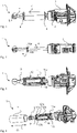
- Locking device 1 for a motor vehicle 20 can be seen.
- the locking device 1 has a support housing 2 which contains a cylinder core (not visible), which is rotatably mounted within the support housing 2 and is reset to its initial position by the return spring 3 .
- the cylinder core merges into a lock cylinder shaft 4, at the end of which is spaced apart from the carrier housing 2 a paddle 5 is arranged.
- the non-rotatable connection between the paddle 5, lock cylinder shaft 4 and cylinder core means that the receptacle 6 in the knob-shaped paddle 5 rotates for coupling to a vehicle lock, so that if it is coupled to the vehicle lock, this is actuated will.
- the vehicle lock can be a door lock of a vehicle door or vehicle hatch, for example.
- the lock cylinder shaft 4 is surrounded by a casing element 7 designed as a sleeve 7, with the sleeve 7 being positioned both axially and perpendicularly to the axial direction, i.e. to the radial direction, by a positioning arrangement 8, of which due to the presence of the sleeve in the view the 1 only small end sections are visible.
- FIG. 14 is another view of the locking device 1 of FIG 1 refer to.
- the representation of 2 does not show the in 1 elements shown positioning assembly, sleeve and support housing. This makes the cylinder core 9 recognizable.
- the structure of the lock cylinder shaft 4 can also be seen, which is essentially circular-cylindrical along a large section. In deviation from the circular-cylindrical design, the lock cylinder shaft 4 has a bulge 9, which serves as a counter-surface 9 for a radial surface present for positioning the positioning arrangement, which in particular 8 is recognizable.
- bulges 10a, 10b can be seen, which are provided for rotationally fixing the positioning arrangement.
- the representation of 3 differs from the representation of figs 1 and 2 Firstly in perspective, the locking device is in perspective 3 namely rotated by 180 ° around the longitudinal axis of the lock cylinder shaft 4.
- the illustration differs in that the jacket element 7 designed as a sleeve is shown transparent, so that the sections of the corresponding components surrounded by the jacket element can be seen, shown with dashed lines due to the arrangement below the sleeve 7 .
- the positioning arrangement has compression springs 11a and 11b pointing radially away from the lock cylinder shaft 4 Spring force on the inner surface of the sleeve 7 exerts.
- This spring force causes a static friction force on the inner lateral surface of sleeve 7, so that rotating sleeve 7 requires a corresponding tangential force, for example along the direction of part 12, which must be greater than the static friction force caused by the compression springs.
- the torque exerted on the shell member by the tangential force mentioned above must be greater than a torque threshold which is determined by the magnitude of the stiction force mentioned above.
- the positioning arrangement 8 has both ends, namely both at the end further away from the carrier housing and at the end closer to the carrier housing Latching elements 12a, 12b, 12c, 12d, which act axially to the effect that they counteract an axial movement of the sleeve 7 in the assembled state.
- the locking elements 12a, 12b, 12c, 12d are spaced apart from one another in such a way that their inwardly facing surfaces correspond to the length 13 of the sleeve 7 and thereby block movement of the sleeve in both possible axial directions and thus position it axially.
- the latching elements 12a and 12b are designed as spring latching elements, that is to say they are on the spring 12'a and, in the case of the latching element 12b, on a corresponding non-visible spring formed as part of the positioning arrangement, so that the sleeve 7 can be pushed over the spring locking elements 12a, 12b to its end position, wherein when the end position is reached, the spring locking elements 12a, 12b in their in 4 spring back shown return position and thereby brings about the above-described axial positioning of the sleeve.
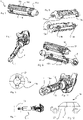
- FIG. 5 a perspective view of the positioning arrangement 8 can be seen.
- the positioning arrangement 8 has spring elements 11a, 11b, 11c and 11d, with which the already described induction of a non-positive connection between the positioning arrangement and the jacket element is brought about.
- the positioning arrangement 8 is shown in an exploded view. It can be seen in particular that in the specific embodiment the positioning arrangement consists of two identical parts which can be connected to one another by means of connecting elements 14a, 14b, 14c and complementary connecting counter-elements 15a, 15b and 15c, the connecting elements being a type of clips as well as in the case of the mating connection elements, corresponding holding fixtures.
- the positioning arrangement has a radial surface 16 on its inner casing, which in the present embodiment is designed as an inner ring connected in one piece to the inner casing.
- the positioning arrangement has two of these radial surfaces 16, 17, which enclose a counter surface 9 positioned complementarily on the outer surface of the lock cylinder shaft 4, designed as an outer ring formed by a radius that is increased compared to the diameter of the lock cylinder shaft, towards the axial Positioning of the positioning arrangement, due to the two radial surfaces 15 and 16 in both directions.
- the radial surface 16 has a radial recess 21, which is positioned complementarily to the bulge 10a, so that both engage in one another when the positioning arrangement is applied, thereby causing the positioning arrangement to be rotationally fixed.
- the sleeve is arranged by means of sliding over the locking elements 12a, 12b designed as spring locking elements.
- a lock arrangement which consists of locking device 1 and lock 19 .
- a motor vehicle 18 can be seen, which has a locking device 1 on the vehicle door 20, among other things.
Landscapes
- Lock And Its Accessories (AREA)
Abstract
Description
- Die Erfindung richtet sich auf eine Verriegelungsvorrichtung, insbesondere eine Verriegelungsvorrichtung, insbesondere für ein Kraftfahrzeug, sowie auf eine Schlossanordnung. Ein weiterer Aspekt der Erfindung betrifft ein Kraftfahrzeug, das eine Verriegelungsvorrichtung aufweist.
- Verriegelungsvorrichtungen sind beispielsweise aus der
DE 10 2009 044 598 A1 bekannt. In der genannten Druckschrift beschriebene Verriegelungsvorrichtungen umfassen ein Trägergehäuse, in welchem ein Zylinderkern drehbar aufgenommen ist. Eine Schließzylinderwelle koppelt den Zylinderkern mit einem von dem Zylinderkern beabstandeten Schloss. - Ein Problem bei mechanischen Verriegelungsvorrichtungen der genannten Art besteht darin, dass sie prinzipbedingt anfällig für mechanische Angriffe sind. Beispielsweise ist aus der Praxis bekannt, dass bei Verriegelungsvorrichtungen an einer Tür eines Kraftfahrzeugs mit einem Ankoppeln eines Werkzeugs an die Schließzylinderwelle und einem gewaltsamen Drehen der Schließzylinderwelle ein Öffnen des Türschlosses erreicht werden kann. Dieses gewaltsame Öffnen geht zwar in der Regel mit Schäden an der Verriegelungsvorrichtung und/oder ihrer Umgebung einher, kann aber im Ergebnis ein erfolgreiches unberechtigtes Eindringen zur Folge haben, welches selbstverständlich unerwünscht ist.
- Vor diesem Hintergrund besteht die Aufgabe, eine konstruktiv elegante Weiterbildung einer Verriegelungsvorrichtung bereitzustellen, die mit wirksamen Schutzmaßnahmen gegen mechanische Angriffe beispielsweise der beschriebenen Art ausgestattet ist.
- Die Aufgabe wird gelöst mit einer Verriegelungsvorrichtung gemäß Anspruch 1. Die Aufgabe wird weiterhin gelöst mit einer Schlossanordnung mit den Merkmalen des Anspruchs 17 und mit einem Kraftfahrzeug mit den Merkmalen des Anspruchs 18.
- Die Verriegelungsvorrichtung weist ein Trägergehäuse auf. Das Trägergehäuse dient dazu, einen Zylinderkern vollständig oder zumindest mit einem Abschnitt des Zylinderkerns aufzunehmen, insbesondere um ihn zu tragen und beispielsweise vor Eindringen von Schmutz zu schützen. Der Zylinderkern ist drehbar ausgeführt, wobei zum Drehen ein Betätigen mit einem in den Zylinderkern eingeführten mechanischen Schlüssel, genauer: Schlüsselbart des Schlüssels, erforderlich ist.
- Wenn die Verriegelungsvorrichtung an einem Kraftfahrzeug angeordnet ist, dann befindet sich die Verriegelungsvorrichtung typischerweise an einer Tür oder einer Klappe des Kraftfahrzeugs, wobei die Verriegelungsvorrichtung eine Öffnung für das Einführen des Schlüsselbarts für dessen Aufnahme in den Zylinderkern aufweist.
- Der Schlüssel ist im Rahmen der vorliegenden Beschreibung nicht als Bestandteil der Verriegelungsvorrichtung angesehen, in alternativen Betrachtungen könnte ein Schlüssel mit einem Schlüsselbart jedoch auch als Bestandteil einer Verriegelungsvorrichtung angesehen werden.
- Mit dem Zylinderkern ist eine Schließzylinderwelle drehfest gekoppelt.
- Am dem Ende der Schließzylinderwelle, das von dem Zylinderkern entfernt ist, ist ein Paddel angeordnet und dabei mit der Schließzylinderwelle drehfest ausgeführt. Das Paddel vollführt aufgrund seiner drehfesten Kopplung mit Schließzylinderwelle und Zylinderkern bei Betätigung des Zylinderkerns ebenfalls eine Drehbewegung. Das Paddel dient der Betätigung des Fahrzeugschlosses, typischerweise eines Türschlosses, welches mit dem Paddel gekoppelt ist.
- Beispielsweise kann vorgesehen sein, dass das Paddel und eine Schlossnuss des Fahrzeugschlosses miteinander gekoppelt sind.
- Der Begriff des Paddels entspricht dem üblichen Sprachgebrauch des Fachmanns auf dem Gebiet der Schließtechnik für eine endseitige Ausformung der Schließzylinderwelle, welche zum Betätigen des Schlosses vorgesehen ist. Dem Begriff Paddel liegt die Tatsache zu Grunde, dass in vielen Ausgestaltungen eine paddelartige Form vorliegt. Im Rahmen der vorliegenden Anmeldung schränkt die Verwendung des Begriffes Paddel die Form des Paddels nicht ein, sodass auch Paddel mit nicht paddelförmiger Form Bestandteil einer erfindungsgemäßen Verriegelungsvorrichtung sein können. Insbesondere sind auch andere mögliche Formen der das Schloss betätigenden Ausformung der Schließzylinderwelle, also des Paddels, möglich, beispielsweise eine kugelige Form, eine Knaufform oder eine elliptische Form, gegebenenfalls auch mit entsprechenden Einbuchtungen.
- Die erfindungsgemäße Verriegelungsvorrichtung zeichnet sich dadurch aus, dass die Schließzylinderwelle zumindest abschnittsweise an einem Mantelelement umgeben ist, das um die Schließzylinderwelle drehbar ist. Das Mantelelement umgibt zumindest einen Abschnitt der Schließzylinderwelle so, dass dass das Mantelelement bei Ausübung eines Drehmoments um die Drehachse der Schließzylinderwelle drehbar ist. Die Anordnung des Mantelelements an der Verriegelungsvorrichtung ist derart ausgeführt, dass das Mantelelement um die Schließzylinderwelle, bevorzugt mit der Drehachse der Zylinderwelle als Drehachse, gedreht werden kann. Mantelelement und Schließzylinderwelle sind somit insbesondere nicht mittelbar oder unmittelbar drehfest miteinander verbunden.
- Das Vorhandensein eines drehbaren Mantelelements, welches um die Schließzylinderwelle drehbar ist, also nicht mit dieser drehfest verbunden ist, bewirkt, dass in dem das Mantelelement aufweisenden Abschnitt der Schließzylinderwelle ein Ausüben eines Drehmoments auf die Schließzylinderwelle selbst, beispielsweise im Rahmen eines gewaltsamen Eindringens zu der Position der Schließzylinderwelle mit einem entsprechenden Werkzeug, beispielsweise mit einer Zange, nicht möglich ist. Denn der direkte Zugriff auf die Schließzylinderwelle ist wegen des Mantelelements nicht möglich und eine indirekte Ausübung des Drehmoments ist aufgrund der Drehbarkeit des Mantelelements - je nach Auslegung der Kopplung zwischen Schließzylinderwelle und Mantelelement, nicht oder nur in vermindertem Maße möglich. Denn eventuell im Bereich der Schließzylinderwelle auf die Verriegelungsvorrichtung einwirkendes Drehmoment führt oberhalb einer bestimmten Drehmomentschwelle zu einem Drehen des Mantelelements. Aufgrund der nicht vorhandenen drehfesten Verbindung mit der Schließzylinderwelle wird folglich ein gewaltsames Öffnen oder eine gewaltsame Zerstörung der Verriegelungsvorrichtung durch unmittelbare Drehmomenteinwirkung auf die Schließzylinderwelle unterbunden. Mit einer erfindungsgemäßen Verriegelungsvorrichtung kann somit dazu beigetragen werden, dass ein gewaltsames Öffnen der Verriegelungsvorrichtung oder eine gewaltsame Zerstörung der Verriegelungsvorrichtung infolge einer Ausübung eines Drehmoments mit einem Werkzeug, beispielsweise mit einer Zange, unterbunden wird.
- In einer bevorzugten Ausführung ist an der Schließzylinderwelle eine Positionieranordnung angeordnet. Die Positionieranordnung fasst zumindest einen Abschnitt der Schließzylinderwelle ein und wird von dieser gehalten. Die Positionieranordnung ist insbesondere axial, also in Richtung der Längsachse der Schließzylinderwelle, an der Schließzylinderwelle bewegungsfest angeordnet. Die Positionieranordnung umhüllt somit die Schließzylinderwelle zumindest in einem Abschnitt der Schließzylinderwelle und steht als eine Art Adapter bereit, mit welcher das Mantelelement an der Verriegelungsvorrichtung im vorgesehenen Abschnitt der Schließzylinderwelle positioniert werden kann. Das Vorsehen einer als Adapter wirkenden Positionieranordnung zum Positionieren des Mantelelements geht mit dem Vorteil einher, dass auf Basis einer gegebenen Konstruktion von Schließzylinderwelle, gegebenenfalls zusätzlich Paddel, Zylinderkern und/oder Trägergehäuse, unterschiedlich ausgebildete Mantelelemente als Bestandteil einer Verriegelungsvorrichtung vorgesehen werden können. So kann beispielsweise für ein erstes Fahrzeugmodell ein erstes Mantelelement genutzt werden und für eine zweites Fahrzeugmodell ein zweites Mantelelement genutzt werden, wobei das erste und das zweite Mantelelement sich beispielsweise in ihren radialen Erstreckungen und/oder in ihrer Höhe, das heißt: in ihrer Erstreckung in axialer Richtung, unterscheiden.
- Bevorzugt ist die Positionieranordnung drehfest an der Schließzylinderwelle angeordnet, sodass ein Drehen der Schließzylinderwelle ein Drehen der Positionieranordnung mit dem gleichen Winkel und Drehsinn bewirkt, dass also die Positionieranordnung relativ zu der Schließzylinderwelle die selbe Orientierung beibehält.
- In einer bevorzugten Ausführungsform umgibt das Mantelelement die Positionieranordnung und wird in axialer und radialer, dass heißt senkrecht zur Längsachse der Schließzylinderwelle, Richtung von dieser festgelegt. Die Positionieranordnung ist demnach derart ausgeformt, dass sie Gestaltungselemente enthält, welche Bewegungen des Mantelelements in axialer Richtung, also in eine zur Schließzylinderwellenerstreckung parallelen Richtung, verhindern sowie außerdem Gestaltungselemente enthält, welche Bewegungen des Mantelelements in radialer Richtung, also in zur Schließzylinderwellenerstreckung senkrechten Richtung verhindern. Mit anderen Worten: Das Mantelelement ist in einer solchen Ausführungsform nur zu Drehbewegungen um die Schließzylinderwelle befähigt, ansonsten jedoch in seinen Bewegungen gehindert oder zumindest in definierter Weise eingeschränkt. Mit Hilfe der Positionieranordnung wird das Mantelelement somit an einer vorgesehenen Position um die Schließzylinderwelle positioniert. Mit der Positionierung durch die Positionieranordnung wird sichergestellt, dass in realen Einsatzsituationen, beispielsweise bei den während eines Fahrens des Kraftfahrzeugs und/oder während eines Öffnens einer die Verriegelungsvorrichtung aufweisenden Fahrzeugtür auftretenden Beschleunigungen, keine nachteiligen Auswirkungen infolge von undefinierten Bewegungen des Mantelelements auftreten. Beispielsweise wird durch das gezielte Positionieren des Mantelelements vermieden, dass das Mantelelement während des üblichen Einsatzes unerwünschte Klappergeräusche verursacht.
- Für das Festlegen des Mantelelements in axialer Richtung weist die Positionieranordnung bevorzugt beidendseitig axial wirkende Rastelemente auf, mit denen das Mantelelement in axialer Richtung gehalten wird. Zumindest an einem Ende sind die Rastelemente bevorzugt Federrastelemente, so dass eine Erstinstallation der Verriegelungseinrichtung dadurch erfolgen kann, dass das Mantelelement über das Federelement hineingeschoben wird und nach Erreichen seiner axialen Position die Federrastelemente zurückfedern und eine Rückbewegung des Mantelelements in axialer Richtung sperren.
- Besonders bevorzugt weist die Positionieranordnung wenigstens eine radial nach außen weisende Druckfeder, besonders bevorzugt mehrere radial nach außen weisende Druckfedern, auf, welche dem Zweck dienen, eine radial oder zumindest eine Radialkomponente aufweisende von der Schließzylinderwelle wegweisende Kraft auf das Mantelelement auszuüben und dadurch einen Kraftschluss zwischen Positionieranordnung und Mantelelement herbeizuführen. Dieser herbeigeführte Kraftschluss zwischen Positionieranordnung und Mantelelement ist dahingehend zu verstehen, dass das Drehen des Mantelelements immer noch möglich ist, jedoch hierfür die Ausübung eines Drehmoments oberhalb eines Mindestdrehmoments auf das Mantelelement erforderlich ist. Es muss also für ein Drehen des Mantelelements mit dem auf das Mantelelement ausgeübten Drehmoment ein Drehmomentschwellwert überschritten werden. Ähnlich der Funktionsweise einer Rutschkupplung bleibt dadurch die gewünschte Funktionalität erhalten, dass unerwünschte, beispielsweise gewaltsame, Drehmomenteinwirkungen auf die Schließzylinderwelle unterbunden werden, da eine Drehbarkeit des Mantelelements zu der Ableitung dieser Drehmomente führen; durch die Kraftschlusskomponente zwischen Positionieranordnung und Mantelelement wird aber ein dauerhaftes zufälliges Drehen des Mantelelements mit entsprechenden Nachteilen wie einer unerwünschten Geräuschentwicklung unterbunden.
- Bevorzugt sind Druckfeder beziehungsweise Druckfedern und das Mantelelement derart aneinander angepasst, dass eine dem Drehen des Mantelelements gegenwirkende Haftreibkraft kleiner ist als eine zum absichtlichen Brechen der Schließzylinderwelle und/oder des Zylinderkerns erforderliche Tangentialkraft. Alternativ oder zusätzlich sind Druckfeder und/oder Mantelelement derart aneinander angepasst, dass eine dem Drehen des Mantelelements entgegenwirkende Haftreibkraft kleiner ist als eine zum Entriegeln des Schlosses mittels Drehens der Schließzylinderwelle erforderliche Tangentialkraft. Es ist also dem Fachmann auferlegt, die Druckfeder beziehungsweise die Druckfedern sowie das Mantelelement aneinander angepasst derart zu dimensionieren, dass ein Drehen des Mantelelements dazu führt, dass ähnlich der Funktionsweise der Rutschkupplung zuerst das Überwinden der Haftreibkraft an dem Innenmantel des Mantelelements und dadurch das Drehen des Mantelelements bewirkt wird, nämlich bei Überschreiten einer oben bereits erwähnten Drehmomentschwelle, so dass bei der maximalen Tangentialkraft vor Überwindung der Haftreibkraft keine Gefahr eines Brechens der Schließzylinderwelle besteht und/oder keine Gefahr eines gewaltsamen Öffnens des Schlosses besteht. Da die genaue Konstruktion und Ausführung von Zylinderkern, Schließzylinderwelle, Paddel sowie Fahrzeugschloss einerseits und in Abhängigkeit davon Mantelelement und Positionieranordnung andererseits sich gegenseitig bedingen, obliegt es dem Fachmann, eine geeignete Dimensionierung der Druckfeder beziehungsweise der Druckfedern vorzunehmen; dies ist jedoch für den Fachmann problemlos umsetzbar.
- Bevorzugt weist die Positionieranordnung an ihrem Innenmantel eine Radialfläche auf, das heißt eine Fläche mit einer zur Schließzylinderwelle parallelen Flächennormale, und die Schließzylinderwelle weist an ihrem Außenmantel eine komplementär positionierte Gegenfläche auf zum axialen Positionieren der Positionieranordnung mittels Sperren einer Axialbewegung aufgrund aneinander anliegender Radialfläche und Gegenfläche.
- Besonders bevorzugt weist die Positionieranordnung eine Radialerhebung auf, welche mit einer Radialausnehmung versehen ist. Weiterhin weist die Schließzylinderwelle an ihrem Außenmantel eine zu der Radialausnehmung komplementär positionierte Auswölbung auf zum Drehfestlegen der Positionieranordnung. Es ist also eine erste Ausformung an der Schließzylinderwelle sowie eine zweite, zu der ersten Ausformung komplementäre, Ausformung an der Positionieranordnung vorgesehen, welche in Zusammenwirkung miteinander verhindern, dass ein Verdrehen der Positionieranordnung relativ zu der Schließzylinderwelle erfolgt. Dadurch, dass Schließzylinderwelle und Positionieranordnung drehfest zueinander ausgebildet sind, sind die Voraussetzungen geschaffen, die Zusammenwirkung aus Positionieranordnung und Mantelelement in konstruktiv besonders elegant umsetzbarer Weise ähnlich der Funktionsweise einer Rutschkupplung auszubilden.
- Besonders bevorzugt ist die Positionieranordnung mehrteilig ausgeführt. Dies kann in besonders vorteilhafter Ausführung ausgeführt sein, indem die Positionieranordnung aus zwei gleichen Teilen besteht, die mittels Verbindungselementen und komplementären Verbindungselementen miteinander verbunden sind. Diese Ausführung hat den Vorteil, dass die Positionieranordnung in besonders einfacher Weise an der Schließzylinderwelle angeordnet werden kann. Durch die Konstruktion der Positionieranordnung aus zwei gleichen Teilen wird die Komplexität der Positionieranordnung verringert, was mit geringen Herstellungskosten einhergeht.
- Besonders bevorzugt ist das Mantelelement eine Hülse, besonders bevorzugt eine einstückige Hülse. Die Hülse ist bevorzugt eine kreiszylindrische Hülse mit dem Vorteil, dass einfache Herstellbarkeit mit geometriebedingt hoher Steifigkeit kombiniert sind.
- Das Mantelelement, das bevorzugt als Hülse ausgebildet ist, ist besonders bevorzugt steif mit dem Vorteil, dass ein Anquetschen des Mantelelements an die Positionieranordnung und/oder an die Schließzylinderwelle zu Ermöglichung des Einbringens eines durch das Mantelelement ja zu verhindernden Drehmoments auf die Schließzylinderwelle unmöglich wird oder zumindest erschwert wird. Die Steifigkeit des Mantelelements ist je nach Anforderungsprofil vom Fachmann einzustellen, beispielweise durch Materialwahl und/oder Einstellung der Manteldicke sowie gegebenenfalls Wahl der Form des Mantelelements. Die Wahl dieser Parameter ist eine Auslegungsaufgabe und stellt für den Fachmann keine prinzipiellen Schwierigkeiten dar.
- In einer vorteilhaften Weiterbildung besteht das Mantelelement aus einem Kunststoff, bevorzugt aus einem Thermoplast wie beispielsweise einem Polycarbonat, einem PET oder einem PE, mit dem Vorteil der kostengünstigen Herstellbarkeit sowie der guten Möglichkeit der Individualisierung beispielsweise durch Einstellung von Farben oder Bekleben mit Logos oder dergleichen. In einer alternativen ebenso vorteilhaften Weiterbildung besteht das Mantelelement aus einem metallischen Material, beispielsweise Stahl, mit dem Vorteil potentiell guter mechanischer Eigenschaften und wertiger Anmutung bei jedoch gegenüber Mantelelementen aus Kunststoff in der Regel höheren Kosten.
- In einer Ausführungsform weist das Paddel eine Kugelform oder eine Knaufform auf. An dem Paddel ist eine Aufnahme zur Kopplung mit einem Fahrzeugschloss, insbesondere einer Nuss des Fahrzeugschlosses, angeordnet.
- Besonders bevorzugt weist die Schließzylinderwelle eine Sollbruchstelle auf, die beispielsweise als Verjüngung im Schließzylinderwellendurchmesser ausgebildet ist. Durch das Vorhandensein einer Sollbruchstelle kann sichergestellt werden, dass selbst in einem Fall, in welchem bereits eine gewaltsame Zerstörung von Mantelelement und Positionieranordnung erfolgt ist, sichergestellt ist, dass ein Drehmomentangriff auf die Schließzylinderwelle aufgrund der vorhandenen Sollbruchstelle in dem Versagen der Schließzylinderwelle mündet, wodurch ein gewaltsames Öffnen des Fahrzeugschlosses selbst erschwert wird.
- Ein Gedanke der Erfindung betrifft eine Schlossanordnung, bestehend aus einer Verriegelungsvorrichtung gemäß obiger Beschreibung und einem von dem Zylinderkern beabstandet angeordneten Schloss, das mit dem Paddel gekoppelt ist, beispielsweise mittels einer Schlossnuss des Schlosses.
- Ein weiterer Gedanke der Erfindung betrifft ein Kraftfahrzeug, das ein Türschloss mit einer Schlossnuss sowie eine Verriegelungsvorrichtung der eingangs genannten Art oder einer ihren Weiterbildungen aufweist. Das Paddel der Verriegelungsvorrichtung ist mit der Schlussnuss gekoppelt derart, dass ein mit einem mechanischen Schlüssel herbeigeführtes Drehen des Zylinderkerns über ein Drehen der Schließzylinderwelle ein Drehen des Paddels herbeiführt, wodurch infolge der Kopplung des Paddels mit der Schlussnuss das Betätigen des Türschlosses bewirkt wird.
- Weitere Einzelheiten, Merkmale und Vorteile des Gegenstandes der Erfindung ergeben sich aus der nachfolgenden Beschreibung im Zusammenhang mit den Figuren, in den beispielhaft Ausführungsbeispiele der Erfindung dargestellt sind.
- Es versteht sich, dass die vorstehend genannten wie auch nachfolgend erläuterten Merkmale nicht nur in der jeweils angegeben Kombination, sondern auch in anderen Kombinationen oder in Alleinstellung verwendbar sind.
- Es zeigen:
-
Figs. 1 bis 4 : schematische Draufsichten auf die Verriegelungseinrichtung; -
Figs. 5 und 6 : perspektivische Draufsicht auf die Positionieranordnung; -
Fig. 7 : Verriegelungsvorrichtung mit einer von zwei Teilen der Positionieranordnung; -
Fig. 8 : Draufsicht auf die Schließzylinderwelle; -
Fig. 9 : Querschnitt A-A; -
Fig. 10 : Draufsicht auf die Verriegelungsvorrichtung; -
Fig. 11 : Verriegelungsvorrichtung mit Türschloss; -
Fig. 12 : Kraftfahrzeug. -
Fig. 1 ist ein Ausführungsbeispiel einer - Verriegelungsvorrichtung 1 ein für ein Kraftfahrzeug 20 zu entnehmen. Die Verriegelungsvorrichtung 1 weist ein Trägergehäuse 2 auf, der einen nicht sichtbaren Zylinderkern enthält, welcher drehbar innerhalb des Trägergehäuses 2 gelagert ist und über die Rückstellfeder 3 in seine Ausgangsposition rückgestellt wird. Der Zylinderkern geht in eine Schließzylinderwelle 4 über, an dessen von dem Trägergehäuse 2 beabstandeten Ende ein Paddel 5 angeordnet ist. Bei Drehen der Schließzylinderwelle 4 um ihre Längsachse dreht sich infolge der drehfesten Verbindung von Paddel 5, Schließzylinderwelle 4 und Zylinderkern die in den knaufförmigen Paddel 5 vorhandene Aufnahme 6 zur Kopplung mit ein Fahrzeugschloss, so dass im Falle einer Kopplung mit dem Fahrzeugschloss dieses betätigt wird. Das Fahrzeugschloss kann beispielsweise ein Türschloss einer Fahrzeugtür oder Fahrzeugklappe sein. Die Schließzylinderwelle 4 ist von einem als Hülse 7 ausgebildeten Mantelelement 7 umgeben, wobei die Hülse 7 sowohl axial als auch in senkrecht zur axialen Richtung, also zur radialen Richtung, von einer Positionieranordnung 8 positioniert wird, von welcher aufgrund des Vorhandenseins der Hülse in der Ansicht der
Fig. 1 nur kleine Endabschnitte sichtbar sind. -
Fig. 2 ist eine andere Ansicht der Verriegelungsvorrichtung 1 derFig. 1 zu entnehmen. Die Darstellung derFig. 2 zeigt nämlich nicht die inFig. 1 abgebildeten Elemente Positionieranordnung, Hülse und Trägergehäuse. Dadurch wird der Zylinderkern 9 erkennbar. Auch die die Struktur der Schließzylinderwelle 4 wird erkennbar, welche entlang eines großen Abschnitts im wesentlichen kreiszylindrisch ist. In Abweichung von der kreiszylindrischen Ausbildung weist die Schließzylinderwelle 4 eine Auswölbung 9 auf, welche als Gegenfläche 9 für eine zur Positionierung der Positionieranordnung vorhandene Radialfläche dient, welche insbesondere inFig. 8 erkennbar ist. Außerdem sind Auswölbungen 10a, 10b zu erkennen, welche für eine Drehfestlegen der Positionieranordnung vorgesehen sind. - Die Darstellung der
Fig. 3 unterscheidet sich von der Darstellung derFigs. 1 und 2 zum einen in der Perspektive, die Verriegelungsvorrichtung ist in der Perspektive derFig. 3 nämlich um 180° um die Längsachse der Schließzylinderwelle 4 gedreht. Zum anderen unterscheidet sich die Darstellung dadurch, dass das als Hülse ausgebildete Mantelelement 7 durchsichtig dargestellt ist, so dass die von dem Mantelelement umgebenen Abschnitte der entsprechenden Bauteile, aufgrund der Anordnung unterhalb der Hülse 7 mit gestrichelten Linien dargestellt, erkennbar sind. Insbesondere ist erkennbar, dass die Positionieranordnung radial von der Schließzylinderwelle 4 wegweisende Druckfedern 11a und 11b aufweist, welche eine Federkraft auf den Innenmantel der Hülse 7 ausübt. Durch diese Federkraft wird eine Haftreibkraft an der inneren Mantelfläche der Hülse 7 herbeigeführt, so dass für ein Drehen der Hülse 7 eine entsprechende Tangentialkraft, beispielsweise entlang der Richtung des Teils 12, erforderlich ist, die größer sein muss als die durch die Druckfedern bewirkte Haftreibkraft. Dadurch wird ähnlich dem Prinzip einer Rutschkupplung eine Drehbarkeit der Hülse sichergestellt, gleichzeitig aber in einem Normalbetrieb eine Bewegungslosigkeit der Verriegelungsvorrichtung 1 sichergestellt, so dass beispielsweise etwaige störende Klappergeräusche vermieden werden können. Das durch die oben erwähnte Tangentialkraft auf das Mantelelement ausgeübte Drehmoment muss größer sein als eine Drehmomentschwelle, welche durch die Größe der oben erwähnten Haftreibkraft bestimmt wird. - In der Darstellung der
Fig. 4 ist die Verriegelungsvorrichtung 1 mit noch nicht angeordneter Hülse 7 gezeigt. In dieser Darstellung sind gut die Federn 11a und 11b erkennbar. Weiterhin ist erkennbar, wie die Ausformung der Positionieranordnung 8 und die Ausformung des Mantelelements 7 zu einer vorteilhaften Zusammenwirkung der erfindungsgemäßen Verriegelungsvorrichtung 1 und ihrer Weiterbildungen führen: Die Positionieranordnung 8 weist beidendseitig, nämlich sowohl am vom Trägergehäuse weiter entfernten Ende als auch am dem Trägergehäuse näheren Ende Rastelemente 12a, 12b, 12c, 12d auf, die dahingehend axial wirken, dass sie einer Axialbewegung der Hülse 7 im montierten Zustand entgegenwirken. Die Rastelemente 12a, 12b, 12c, 12d sind derart von einander beabstandet, dass ihre nach innen weisenden Flächen der Länge 13 der Hülse 7 entsprechen und dadurch in beide mögliche axiale Richtungen eine Bewegung der Hülse sperren und diese somit axial positionieren. Die Rastelemente 12a und 12b sind als Federrastelemente ausgebildet, das heißt: sie sind an Feder 12'a und im Fall des Rastelements 12b an einer entsprechenden nicht sichtbaren Feder als Bestandteil der Positionieranordnung ausgebildet, so dass die Hülse 7 über die Federrastelemente 12a, 12b zu seiner Endposition hin übergeschoben werden kann, wobei bei Erreichen der Endposition die Federrastelemente 12a, 12b in ihre inFig. 4 dargestellte Rückstellposition zurückfedern und dadurch die oben beschriebene axiale Positionierung der Hülse herbeiführt. -
Fig. 5 ist eine perspektivische Darstellung der Positionieranordnung 8 zu entnehmen. Die Positionieranordnung 8 weist Federelemente 11a, 11b, 11c und 11d auf, mit welcher die bereits beschriebene Herbeiführung eines Kraftschlusses zwischen Positionieranordnung und Mantelelement bewirkt wird. - In
Fig. 6 ist die Positionieranordnung 8 in Explosionsdarstellung gezeigt. Es ist insbesondere erkennbar, dass in der speziellen Ausführungsform die Positionieranordnung aus zwei gleichen Teilen besteht, die mittels Verbindungselementen 14a, 14b, 14c sowie komplementären Verbindungsgegenelementen 15a, 15b und 15c miteinander verbindbar sind, wobei es sich bei den Verbindungselementen um eine Art Clipse handelt sowie bei den Verbindungsgegenelementen um entsprechende Halteaufnahmen. -
Fig. 7 ist eine Darstellung zu entnehmen, in welcher einer der beiden Teile der Positionieranordnung bereits an der Schließzylinderwelle 4 an dieser anliegend und diese einfassend dargestellt ist. Insbesondere ist zu entnehmen, dass die Positionieranordnung an ihrem Innenmantel eine Radialfläche 16 aufweist, welche in der vorliegenden Ausführungsform als einstückig mit Innenmantel verbundener Innenring ausgebildet ist. In der gezeigten Ausführungsform weist die Positionieranordnung zwei dieser Radialflächen 16, 17 auf, welche eine am Außenmantel der Schließzylinderwelle 4 komplementär positionierte Gegenfläche 9, ausgebildet als Außenring gebildet durch gegenüber dem Durchmesser der Schließzylinderwelle erhöhtem Radius, einfasst zum axialen Positionieren der Positionieranordnung, und zwar aufgrund der beiden Radialflächen 15 und 16 in beide Richtungen. - Dies ist in
Fig. 8 noch besser zu sehen. Zusätzlich ist erkennbar, dass die Radialfläche 16 eine Radialausnehmung 21 aufweist, die komplementär zu der Auswölbung 10a positioniert ist, sodass beide bei angelegter Positionieranordnung ineinander eingreifen und dadurch eine Drehfestlegung der Positionieranordnung bewirken. Auf der Auswölbung 10a gegenüberliegenden Seite ist eine weitere Auswölbung 10b vorhanden, welche in die Radialausnehmung des anderen Teils der Posotionieranordnung eingreift. Dies ist inFig. 9 zu erkennen, welche eine Schnittdarstellung eines Schnitts von Positionieranorndnung und Schließzylinderwelle an einer Längsposition zeigt, an welcher die Auswölbungen 10a, 10b positioniert sind. - In
Fig. 10 ist dargestellt, dass eine Anordnung der Hülse mittels Schiebens über die als Federrastelemente ausgebildeten Rastelemente 12a, 12b erfolgt. - In
Fig. 11 ist eine Schlossanordnung gezeigt, welche aus Verriegelungsvorrichtung 1 und Schloss 19 besteht. -
Fig. 12 ist ein Kraftfahrzeug 18 zu entnehmen, welches unter anderem an der Fahrzeugtür 20 eine Verriegelungsvorrichtung 1 aufweist.
Claims (18)
- Verriegelungsvorrichtung (1), insbesondere für ein Kraftfahrzeug (20), wobei die Verriegelungsvorrichtung (1) aufweist:Ein Trägergehäuse (2),einen abschnittsweise oder vollständig in dem Trägergehäuse (2) angeordneten Zylinderkern (9), der mit einem mechanischen Schlüssel drehbar ist,eine drehfest mit dem Zylinderkern (9) gekoppelte Schließzylinderwelle (4) mit einem Paddel (5) zum Übertragen einer Drehbewegung des Zylinderkerns (9) zu dem Paddel (5) zur Betätigung eines mit dem Paddel (5) gekoppelten Schlosses (19), insbesondere Fahrzeugschlosses,dadurch gekennzeichnet, dass die Schließzylinderwelle (4) zumindest abschnittsweise von einem Mantelelement (7) umgeben ist, das um die Schließzylinderwelle (4) drehbar ist.
- Verriegelungsvorrichtung (1) nach Anspruch 1, wobei an der Schließzylinderwelle (4) eine Positionieranordnung (8) angeordnet ist.
- Verriegelungsvorrichtung (1) nach Anspruch 2, wobei das Mantelelement (7) die Positionieranordnung (8) umfasst und dabei in axialer und in radialer Richtung von dieser festgelegt ist.
- Verriegelungsvorrichtung (1) nach Anspruch 2 oder nach Anspruch 3, wobei die Positionieranordnung (8) beidendseitig axial wirkende Rastelemente (12a, 12b, 12c, 12d) aufweist, mit denen das Mantelelement (7) in axialer Richtung gehalten wird, wobei an einem Ende die Rastelemente Feder-Rastelemente (12a, 12b) sind zum Ermöglichen eines Überschiebens des Mantelelements (7) bei einer Erstmontage der Verriegelungseinrichtung (1).
- Verriegelungsvorrichtung (1) nach einem der Ansprüche 2 bis 4, wobei die Positionieranordnung (8) eine oder mehrere radial nach außen weisende Druckfeder beziehungsweise Druckfedern (11a, 11b, 11c, 11d) aufweist zum Herbeiführen eines Kraftschlusses zwischen Positionieranordnung (8) und Mantelelement (7).
- Verriegelungsvorrichtung (1) nach Anspruch 5, wobei
die Druckfeder (11a, 11b, 11c, 11d) und das Mantelelement (7) derart aneinander angepasst sind, dass eine dem Drehen des Mantelelements (7) gegenwirkende Haftreibkraft kleiner ist als eine zum absichtlichen Brechen der Schließzylinderwelle (4) und/oder des Zylinderkerns erforderliche Tangentialkraft, und/oder wobei
die Druckfeder (11a, 11b, 11c, 11d) und das Mantelelement (7) derart aneinander angepasst sind, dass eine dem Drehen des Mantelelements (7) gegenwirkende Haftreibkraft kleiner ist als eine zum Entriegeln des Schlosses (18) durch Drehen der Schließzylinderwelle (4) erforderliche Tangentialkraft. - Verriegelungsvorrichtung (1) nach einem der Ansprüche 2 bis 6, wobei die Positionieranordnung (8) an ihrem Innenmantel eine Radialfläche (16, 17) aufweist und die Schließzylinderwelle (4) an ihrem Außenmantel eine komplementär positionierte Gegenfläche (18) aufweist zum axialen Positionieren der Positionieranordnung (8).
- Verriegelungsvorrichtung (1) nach einem der Ansprüche 2 bis 7, wobei die Positionieranordnung (8) relativ zu der Schließzylinderwelle (4) drehfest an der Schließzylinderwelle (4) angeordnet ist.
- Verriegelungsvorrichtung (1) nach einem der Ansprüche 2 bis 8, wobei die Positionieranordnung (8) an ihrem Innenmantel eine Radialerhebung aufweist, bevorzugt die Radialfläche (16, 17), mit einer Radialausnehmung (21) und die Schließzylinderwelle (4) an ihrem Außenmantel eine zu der Radialausnehmung (16, 17) komplementär positionierte Auswölbung (10a, 10b) aufweist zum Drehfestlegen der Positionieranordnung (8).
- Verriegelungsvorrichtung (1) nach einem der Ansprüche 2 bis 9, wobei die Positionieranordnung (8) mehrteilig ausgeführt ist.
- Verriegelungsvorrichtung (1) nach einem der Ansprüche 2 bis 10, wobei die Positionieranordnung (8) aus zwei gleichen Teilen besteht, die mittels Verbindungselementen (14a, 14b, 14c) und komplementären Verbindungsgegenelementen (15a, 15b, 15c) miteinander verbunden sind.
- Verriegelungsvorrichtung (1) nach einem der vorhergehenden Ansprüche, wobei das Mantelelement (7) eine Hülse ist, bevorzugt eine einstückge Hülse.
- Verriegelungsvorrichtung (1) nach einem der vorhergehenden Ansprüche, wobei das Mantelelement (7) steif ist.
- Verriegelungsvorrichtung (1) nach einem der vorhergehenden Ansprüche, wobei das Mantelelement (7) aus einem Kunststoff, bevorzugt einem Thermoplast, oder aus einem metallischen Material, bevorzugt Stahl, besteht.
- Verriegelungsvorrichtung (1) nach einem der vorhergehenden Ansprüche, wobei das Paddel (5) eine Kugelform oder eine Knaufform aufweist, an der eine Aufnahme zur Kopplung mit einem Schloss (19), insbesondere einer Nuss des Schlosses, angeordnet ist.
- Verriegelungsvorrichtung (1) nach einem der vorhergehenden Ansprüche, wobei die Schließzylinderwelle (4) eine Sollbruchstelle aufweist.
- Schlossanordnung, bestehend aus einer Verriegelungsvorrichtung (1) nach einem der vorhergehenden Ansprüche und einem von dem Zylinderkern (9) beabstandet angeordneten Schloss (8), das mit dem Paddel (5) gekoppelt ist.
- Kraftfahrzeug (18), aufweisend ein Türschloss (19) mit einer Schlossnuss sowie eine an einer Fahrzeugtür (20) oder Fahrzeugklappe angeordnete Verriegelungsvorrichtung (1) nach einem der Ansprüche 1 bis 16, dadurch gekennzeichnet, dass das Paddel (5) mit der Schlossnuss gekoppelt ist und ein mit dem mechanischen Schlüssel herbeigeführtes Drehen des Zylinderkerns über ein Drehen der Schließzylinderwelle (4) ein Drehen des Paddels (6) herbeiführt, welches infolge der Kopplung des Paddels (6) mit der Schlossnuss (8) das Betätigen des Türschlosses (19) bewirkt.
Applications Claiming Priority (1)
| Application Number | Priority Date | Filing Date | Title |
|---|---|---|---|
| DE102020124765.6A DE102020124765A1 (de) | 2020-09-23 | 2020-09-23 | Verriegelungsvorrichtung, Schlossanordnung und Kraftfahrzeug |
Publications (2)
| Publication Number | Publication Date |
|---|---|
| EP3974606A1 true EP3974606A1 (de) | 2022-03-30 |
| EP3974606B1 EP3974606B1 (de) | 2023-05-10 |
Family
ID=76180877
Family Applications (1)
| Application Number | Title | Priority Date | Filing Date |
|---|---|---|---|
| EP21176406.3A Active EP3974606B1 (de) | 2020-09-23 | 2021-05-28 | Verriegelungsvorrichtung, schlossanordnung und kraftfahrzeug |
Country Status (2)
| Country | Link |
|---|---|
| EP (1) | EP3974606B1 (de) |
| DE (1) | DE102020124765A1 (de) |
Citations (7)
| Publication number | Priority date | Publication date | Assignee | Title |
|---|---|---|---|---|
| EP1580358A1 (de) * | 2004-03-25 | 2005-09-28 | Valeo Securite Habitacle S.A.S. | Schutz für Verstellvorrichtung zur Verschlussbetätigung mittels eines Schlosses |
| FR2873734A1 (fr) * | 2004-07-30 | 2006-02-03 | Peugeot Citroen Automobiles Sa | Systeme anti-effraction pour verrou de fermeture d'une portiere de vehicule, notamment automobile |
| JP2009180033A (ja) * | 2008-01-31 | 2009-08-13 | Alpha Corp | 車両用ドアロック装置 |
| DE102009044598A1 (de) | 2009-11-20 | 2011-05-26 | Huf Hülsbeck & Fürst Gmbh & Co. Kg | Verriegelungsvorrichtung eines Kraftfahrzeugs |
| US8262143B2 (en) * | 2005-09-15 | 2012-09-11 | Valeo Securite Habitacle S.A.S. | Driving device for actuating a latch via a lock |
| FR3000760A1 (fr) * | 2013-01-09 | 2014-07-11 | Peugeot Citroen Automobiles Sa | Rame de liaison entre le verrou et la serrure d'un ouvrant de vehicule automobile, comportant une piece de protection anti-vol |
| FR3000762A1 (fr) * | 2013-01-09 | 2014-07-11 | Peugeot Citroen Automobiles Sa | Rame de liaison entre le verrou et la serrure d’un ouvrant de vehicule automobile, comportant une zone fusible |
-
2020
- 2020-09-23 DE DE102020124765.6A patent/DE102020124765A1/de active Pending
-
2021
- 2021-05-28 EP EP21176406.3A patent/EP3974606B1/de active Active
Patent Citations (7)
| Publication number | Priority date | Publication date | Assignee | Title |
|---|---|---|---|---|
| EP1580358A1 (de) * | 2004-03-25 | 2005-09-28 | Valeo Securite Habitacle S.A.S. | Schutz für Verstellvorrichtung zur Verschlussbetätigung mittels eines Schlosses |
| FR2873734A1 (fr) * | 2004-07-30 | 2006-02-03 | Peugeot Citroen Automobiles Sa | Systeme anti-effraction pour verrou de fermeture d'une portiere de vehicule, notamment automobile |
| US8262143B2 (en) * | 2005-09-15 | 2012-09-11 | Valeo Securite Habitacle S.A.S. | Driving device for actuating a latch via a lock |
| JP2009180033A (ja) * | 2008-01-31 | 2009-08-13 | Alpha Corp | 車両用ドアロック装置 |
| DE102009044598A1 (de) | 2009-11-20 | 2011-05-26 | Huf Hülsbeck & Fürst Gmbh & Co. Kg | Verriegelungsvorrichtung eines Kraftfahrzeugs |
| FR3000760A1 (fr) * | 2013-01-09 | 2014-07-11 | Peugeot Citroen Automobiles Sa | Rame de liaison entre le verrou et la serrure d'un ouvrant de vehicule automobile, comportant une piece de protection anti-vol |
| FR3000762A1 (fr) * | 2013-01-09 | 2014-07-11 | Peugeot Citroen Automobiles Sa | Rame de liaison entre le verrou et la serrure d’un ouvrant de vehicule automobile, comportant une zone fusible |
Also Published As
| Publication number | Publication date |
|---|---|
| EP3974606B1 (de) | 2023-05-10 |
| DE102020124765A1 (de) | 2022-03-24 |
Similar Documents
| Publication | Publication Date | Title |
|---|---|---|
| DE102007044088B9 (de) | Binär codierter Schlüssel und manipulationssicheres Schloss | |
| DE102011051553B4 (de) | Beschlag für Fenster oder Türen | |
| DE102014212863B4 (de) | Klappensteuerung | |
| EP3066282B1 (de) | Schliesseinrichtung für eine tür oder klappe | |
| DE602005001818T2 (de) | Kupplungsmechanismus für Schlösser | |
| EP2796646B1 (de) | Hangschloss | |
| EP1719861B1 (de) | Schliessszylinder für ein elektronisches Schliesssystem | |
| DE202005005774U1 (de) | Rüttelsicherer Vorreiberverschluss | |
| EP1077174A2 (de) | Klobenschloss | |
| EP1357243B1 (de) | Betätigungshandhabe | |
| EP3784855B1 (de) | Kraftfahrzeugschloss | |
| DE69904408T2 (de) | Schlüssel mit bewegbarem stift, sicherheitsdrehzylinder und damit ausgerüstetes schloss | |
| DE102007011554B4 (de) | Koppeleinheit für elektronische Schließ-Systeme | |
| EP3258036B1 (de) | Beschlag mit einer beschlagsicherung | |
| DE102009044598A1 (de) | Verriegelungsvorrichtung eines Kraftfahrzeugs | |
| EP3974606B1 (de) | Verriegelungsvorrichtung, schlossanordnung und kraftfahrzeug | |
| EP3795785B1 (de) | Schloss-schlüssel-system | |
| DE102015108675A1 (de) | Zylinderschlossanordnung | |
| DE102010022373A1 (de) | Dämpfer | |
| EP0713946A2 (de) | Möbelschloss oder Verschluss | |
| EP1722050B1 (de) | Drehriegelschloss | |
| EP0036141B1 (de) | Steckschlüsselbetätigbare Arretierungsvorrichtung | |
| DE69208814T2 (de) | Haltevorrichtung für den Schlüssel eines Schlosses | |
| DE102014114580A1 (de) | Kraftfahrzeugtürverschluss | |
| DE10116739B4 (de) | Kraftfahrzeugschließvorrichtung mit Welle als Kupplungsmittel |
Legal Events
| Date | Code | Title | Description |
|---|---|---|---|
| PUAI | Public reference made under article 153(3) epc to a published international application that has entered the european phase |
Free format text: ORIGINAL CODE: 0009012 |
|
| STAA | Information on the status of an ep patent application or granted ep patent |
Free format text: STATUS: THE APPLICATION HAS BEEN PUBLISHED |
|
| AK | Designated contracting states |
Kind code of ref document: A1 Designated state(s): AL AT BE BG CH CY CZ DE DK EE ES FI FR GB GR HR HU IE IS IT LI LT LU LV MC MK MT NL NO PL PT RO RS SE SI SK SM TR |
|
| STAA | Information on the status of an ep patent application or granted ep patent |
Free format text: STATUS: REQUEST FOR EXAMINATION WAS MADE |
|
| 17P | Request for examination filed |
Effective date: 20220414 |
|
| RBV | Designated contracting states (corrected) |
Designated state(s): AL AT BE BG CH CY CZ DE DK EE ES FI FR GB GR HR HU IE IS IT LI LT LU LV MC MK MT NL NO PL PT RO RS SE SI SK SM TR |
|
| GRAP | Despatch of communication of intention to grant a patent |
Free format text: ORIGINAL CODE: EPIDOSNIGR1 |
|
| STAA | Information on the status of an ep patent application or granted ep patent |
Free format text: STATUS: GRANT OF PATENT IS INTENDED |
|
| INTG | Intention to grant announced |
Effective date: 20230209 |
|
| GRAS | Grant fee paid |
Free format text: ORIGINAL CODE: EPIDOSNIGR3 |
|
| GRAA | (expected) grant |
Free format text: ORIGINAL CODE: 0009210 |
|
| STAA | Information on the status of an ep patent application or granted ep patent |
Free format text: STATUS: THE PATENT HAS BEEN GRANTED |
|
| AK | Designated contracting states |
Kind code of ref document: B1 Designated state(s): AL AT BE BG CH CY CZ DE DK EE ES FI FR GB GR HR HU IE IS IT LI LT LU LV MC MK MT NL NO PL PT RO RS SE SI SK SM TR |
|
| REG | Reference to a national code |
Ref country code: GB Ref legal event code: FG4D Free format text: NOT ENGLISH |
|
| REG | Reference to a national code |
Ref country code: AT Ref legal event code: REF Ref document number: 1566828 Country of ref document: AT Kind code of ref document: T Effective date: 20230515 Ref country code: CH Ref legal event code: EP |
|
| REG | Reference to a national code |
Ref country code: DE Ref legal event code: R096 Ref document number: 502021000664 Country of ref document: DE |
|
| REG | Reference to a national code |
Ref country code: IE Ref legal event code: FG4D Free format text: LANGUAGE OF EP DOCUMENT: GERMAN |
|
| P01 | Opt-out of the competence of the unified patent court (upc) registered |
Effective date: 20230510 |
|
| REG | Reference to a national code |
Ref country code: LT Ref legal event code: MG9D |
|
| REG | Reference to a national code |
Ref country code: NL Ref legal event code: MP Effective date: 20230510 |
|
| PG25 | Lapsed in a contracting state [announced via postgrant information from national office to epo] |
Ref country code: SE Free format text: LAPSE BECAUSE OF FAILURE TO SUBMIT A TRANSLATION OF THE DESCRIPTION OR TO PAY THE FEE WITHIN THE PRESCRIBED TIME-LIMIT Effective date: 20230510 Ref country code: PT Free format text: LAPSE BECAUSE OF FAILURE TO SUBMIT A TRANSLATION OF THE DESCRIPTION OR TO PAY THE FEE WITHIN THE PRESCRIBED TIME-LIMIT Effective date: 20230911 Ref country code: NO Free format text: LAPSE BECAUSE OF FAILURE TO SUBMIT A TRANSLATION OF THE DESCRIPTION OR TO PAY THE FEE WITHIN THE PRESCRIBED TIME-LIMIT Effective date: 20230810 Ref country code: NL Free format text: LAPSE BECAUSE OF FAILURE TO SUBMIT A TRANSLATION OF THE DESCRIPTION OR TO PAY THE FEE WITHIN THE PRESCRIBED TIME-LIMIT Effective date: 20230510 Ref country code: ES Free format text: LAPSE BECAUSE OF FAILURE TO SUBMIT A TRANSLATION OF THE DESCRIPTION OR TO PAY THE FEE WITHIN THE PRESCRIBED TIME-LIMIT Effective date: 20230510 |
|
| PG25 | Lapsed in a contracting state [announced via postgrant information from national office to epo] |
Ref country code: RS Free format text: LAPSE BECAUSE OF FAILURE TO SUBMIT A TRANSLATION OF THE DESCRIPTION OR TO PAY THE FEE WITHIN THE PRESCRIBED TIME-LIMIT Effective date: 20230510 Ref country code: PL Free format text: LAPSE BECAUSE OF FAILURE TO SUBMIT A TRANSLATION OF THE DESCRIPTION OR TO PAY THE FEE WITHIN THE PRESCRIBED TIME-LIMIT Effective date: 20230510 Ref country code: LV Free format text: LAPSE BECAUSE OF FAILURE TO SUBMIT A TRANSLATION OF THE DESCRIPTION OR TO PAY THE FEE WITHIN THE PRESCRIBED TIME-LIMIT Effective date: 20230510 Ref country code: LT Free format text: LAPSE BECAUSE OF FAILURE TO SUBMIT A TRANSLATION OF THE DESCRIPTION OR TO PAY THE FEE WITHIN THE PRESCRIBED TIME-LIMIT Effective date: 20230510 Ref country code: IS Free format text: LAPSE BECAUSE OF FAILURE TO SUBMIT A TRANSLATION OF THE DESCRIPTION OR TO PAY THE FEE WITHIN THE PRESCRIBED TIME-LIMIT Effective date: 20230910 Ref country code: HR Free format text: LAPSE BECAUSE OF FAILURE TO SUBMIT A TRANSLATION OF THE DESCRIPTION OR TO PAY THE FEE WITHIN THE PRESCRIBED TIME-LIMIT Effective date: 20230510 Ref country code: GR Free format text: LAPSE BECAUSE OF FAILURE TO SUBMIT A TRANSLATION OF THE DESCRIPTION OR TO PAY THE FEE WITHIN THE PRESCRIBED TIME-LIMIT Effective date: 20230811 |
|
| PG25 | Lapsed in a contracting state [announced via postgrant information from national office to epo] |
Ref country code: FI Free format text: LAPSE BECAUSE OF FAILURE TO SUBMIT A TRANSLATION OF THE DESCRIPTION OR TO PAY THE FEE WITHIN THE PRESCRIBED TIME-LIMIT Effective date: 20230510 |
|
| PG25 | Lapsed in a contracting state [announced via postgrant information from national office to epo] |
Ref country code: SK Free format text: LAPSE BECAUSE OF FAILURE TO SUBMIT A TRANSLATION OF THE DESCRIPTION OR TO PAY THE FEE WITHIN THE PRESCRIBED TIME-LIMIT Effective date: 20230510 |
|
| REG | Reference to a national code |
Ref country code: BE Ref legal event code: MM Effective date: 20230531 |
|
| PG25 | Lapsed in a contracting state [announced via postgrant information from national office to epo] |
Ref country code: SM Free format text: LAPSE BECAUSE OF FAILURE TO SUBMIT A TRANSLATION OF THE DESCRIPTION OR TO PAY THE FEE WITHIN THE PRESCRIBED TIME-LIMIT Effective date: 20230510 Ref country code: SK Free format text: LAPSE BECAUSE OF FAILURE TO SUBMIT A TRANSLATION OF THE DESCRIPTION OR TO PAY THE FEE WITHIN THE PRESCRIBED TIME-LIMIT Effective date: 20230510 Ref country code: RO Free format text: LAPSE BECAUSE OF FAILURE TO SUBMIT A TRANSLATION OF THE DESCRIPTION OR TO PAY THE FEE WITHIN THE PRESCRIBED TIME-LIMIT Effective date: 20230510 Ref country code: LU Free format text: LAPSE BECAUSE OF NON-PAYMENT OF DUE FEES Effective date: 20230528 Ref country code: EE Free format text: LAPSE BECAUSE OF FAILURE TO SUBMIT A TRANSLATION OF THE DESCRIPTION OR TO PAY THE FEE WITHIN THE PRESCRIBED TIME-LIMIT Effective date: 20230510 Ref country code: DK Free format text: LAPSE BECAUSE OF FAILURE TO SUBMIT A TRANSLATION OF THE DESCRIPTION OR TO PAY THE FEE WITHIN THE PRESCRIBED TIME-LIMIT Effective date: 20230510 Ref country code: CZ Free format text: LAPSE BECAUSE OF FAILURE TO SUBMIT A TRANSLATION OF THE DESCRIPTION OR TO PAY THE FEE WITHIN THE PRESCRIBED TIME-LIMIT Effective date: 20230510 |
|
| REG | Reference to a national code |
Ref country code: DE Ref legal event code: R097 Ref document number: 502021000664 Country of ref document: DE |
|
| PG25 | Lapsed in a contracting state [announced via postgrant information from national office to epo] |
Ref country code: MC Free format text: LAPSE BECAUSE OF FAILURE TO SUBMIT A TRANSLATION OF THE DESCRIPTION OR TO PAY THE FEE WITHIN THE PRESCRIBED TIME-LIMIT Effective date: 20230510 |
|
| REG | Reference to a national code |
Ref country code: IE Ref legal event code: MM4A |
|
| PG25 | Lapsed in a contracting state [announced via postgrant information from national office to epo] |
Ref country code: MC Free format text: LAPSE BECAUSE OF FAILURE TO SUBMIT A TRANSLATION OF THE DESCRIPTION OR TO PAY THE FEE WITHIN THE PRESCRIBED TIME-LIMIT Effective date: 20230510 |
|
| PLBE | No opposition filed within time limit |
Free format text: ORIGINAL CODE: 0009261 |
|
| STAA | Information on the status of an ep patent application or granted ep patent |
Free format text: STATUS: NO OPPOSITION FILED WITHIN TIME LIMIT |
|
| PG25 | Lapsed in a contracting state [announced via postgrant information from national office to epo] |
Ref country code: IE Free format text: LAPSE BECAUSE OF NON-PAYMENT OF DUE FEES Effective date: 20230528 |
|
| 26N | No opposition filed |
Effective date: 20240213 |
|
| PG25 | Lapsed in a contracting state [announced via postgrant information from national office to epo] |
Ref country code: IE Free format text: LAPSE BECAUSE OF NON-PAYMENT OF DUE FEES Effective date: 20230528 |
|
| PG25 | Lapsed in a contracting state [announced via postgrant information from national office to epo] |
Ref country code: SI Free format text: LAPSE BECAUSE OF FAILURE TO SUBMIT A TRANSLATION OF THE DESCRIPTION OR TO PAY THE FEE WITHIN THE PRESCRIBED TIME-LIMIT Effective date: 20230510 |
|
| PG25 | Lapsed in a contracting state [announced via postgrant information from national office to epo] |
Ref country code: SI Free format text: LAPSE BECAUSE OF FAILURE TO SUBMIT A TRANSLATION OF THE DESCRIPTION OR TO PAY THE FEE WITHIN THE PRESCRIBED TIME-LIMIT Effective date: 20230510 Ref country code: IT Free format text: LAPSE BECAUSE OF FAILURE TO SUBMIT A TRANSLATION OF THE DESCRIPTION OR TO PAY THE FEE WITHIN THE PRESCRIBED TIME-LIMIT Effective date: 20230510 Ref country code: BE Free format text: LAPSE BECAUSE OF NON-PAYMENT OF DUE FEES Effective date: 20230531 |
|
| PG25 | Lapsed in a contracting state [announced via postgrant information from national office to epo] |
Ref country code: BG Free format text: LAPSE BECAUSE OF FAILURE TO SUBMIT A TRANSLATION OF THE DESCRIPTION OR TO PAY THE FEE WITHIN THE PRESCRIBED TIME-LIMIT Effective date: 20230510 |
|
| PG25 | Lapsed in a contracting state [announced via postgrant information from national office to epo] |
Ref country code: BG Free format text: LAPSE BECAUSE OF FAILURE TO SUBMIT A TRANSLATION OF THE DESCRIPTION OR TO PAY THE FEE WITHIN THE PRESCRIBED TIME-LIMIT Effective date: 20230510 |
|
| REG | Reference to a national code |
Ref country code: CH Ref legal event code: PL |
|
| PG25 | Lapsed in a contracting state [announced via postgrant information from national office to epo] |
Ref country code: CH Free format text: LAPSE BECAUSE OF NON-PAYMENT OF DUE FEES Effective date: 20240531 |
|
| PGFP | Annual fee paid to national office [announced via postgrant information from national office to epo] |
Ref country code: DE Payment date: 20250531 Year of fee payment: 5 |
|
| PGFP | Annual fee paid to national office [announced via postgrant information from national office to epo] |
Ref country code: FR Payment date: 20250523 Year of fee payment: 5 |
|
| PGFP | Annual fee paid to national office [announced via postgrant information from national office to epo] |
Ref country code: AT Payment date: 20250721 Year of fee payment: 5 |
|
| PG25 | Lapsed in a contracting state [announced via postgrant information from national office to epo] |
Ref country code: CY Free format text: LAPSE BECAUSE OF FAILURE TO SUBMIT A TRANSLATION OF THE DESCRIPTION OR TO PAY THE FEE WITHIN THE PRESCRIBED TIME-LIMIT; INVALID AB INITIO Effective date: 20210528 |
|
| PG25 | Lapsed in a contracting state [announced via postgrant information from national office to epo] |
Ref country code: HU Free format text: LAPSE BECAUSE OF FAILURE TO SUBMIT A TRANSLATION OF THE DESCRIPTION OR TO PAY THE FEE WITHIN THE PRESCRIBED TIME-LIMIT; INVALID AB INITIO Effective date: 20210528 |
|
| PG25 | Lapsed in a contracting state [announced via postgrant information from national office to epo] |
Ref country code: TR Free format text: LAPSE BECAUSE OF FAILURE TO SUBMIT A TRANSLATION OF THE DESCRIPTION OR TO PAY THE FEE WITHIN THE PRESCRIBED TIME-LIMIT Effective date: 20230510 |
|
| GBPC | Gb: european patent ceased through non-payment of renewal fee |
Effective date: 20250528 |
|
| PG25 | Lapsed in a contracting state [announced via postgrant information from national office to epo] |
Ref country code: GB Free format text: LAPSE BECAUSE OF NON-PAYMENT OF DUE FEES Effective date: 20250528 |