EP3974247B1 - Vorrichtung und verfahren zur leistungssteuerung eines parallelen multipack-systems - Google Patents
Vorrichtung und verfahren zur leistungssteuerung eines parallelen multipack-systems Download PDFInfo
- Publication number
- EP3974247B1 EP3974247B1 EP20881117.4A EP20881117A EP3974247B1 EP 3974247 B1 EP3974247 B1 EP 3974247B1 EP 20881117 A EP20881117 A EP 20881117A EP 3974247 B1 EP3974247 B1 EP 3974247B1
- Authority
- EP
- European Patent Office
- Prior art keywords
- pack
- power
- battery
- parallel multi
- total
- Prior art date
- Legal status (The legal status is an assumption and is not a legal conclusion. Google has not performed a legal analysis and makes no representation as to the accuracy of the status listed.)
- Active
Links
Images

Classifications
-
- H—ELECTRICITY
- H02—GENERATION; CONVERSION OR DISTRIBUTION OF ELECTRIC POWER
- H02J—ELECTRIC POWER NETWORKS; CIRCUIT ARRANGEMENTS OR SYSTEMS FOR SUPPLYING OR DISTRIBUTING ELECTRIC POWER; SYSTEMS FOR STORING ELECTRIC ENERGY
- H02J7/00—Circuit arrangements for charging or discharging batteries or for supplying loads from batteries
- H02J7/50—Circuit arrangements for charging or discharging batteries or for supplying loads from batteries acting upon multiple batteries simultaneously or sequentially
-
- H—ELECTRICITY
- H02—GENERATION; CONVERSION OR DISTRIBUTION OF ELECTRIC POWER
- H02J—ELECTRIC POWER NETWORKS; CIRCUIT ARRANGEMENTS OR SYSTEMS FOR SUPPLYING OR DISTRIBUTING ELECTRIC POWER; SYSTEMS FOR STORING ELECTRIC ENERGY
- H02J7/00—Circuit arrangements for charging or discharging batteries or for supplying loads from batteries
- H02J7/90—Regulation of charging or discharging current or voltage
- H02J7/933—Regulation of charging or discharging current or voltage the cycle being controlled or terminated in response to electric parameters
-
- B—PERFORMING OPERATIONS; TRANSPORTING
- B60—VEHICLES IN GENERAL
- B60L—PROPULSION OF ELECTRICALLY-PROPELLED VEHICLES; SUPPLYING ELECTRIC POWER FOR AUXILIARY EQUIPMENT OF ELECTRICALLY-PROPELLED VEHICLES; ELECTRODYNAMIC BRAKE SYSTEMS FOR VEHICLES IN GENERAL; MAGNETIC SUSPENSION OR LEVITATION FOR VEHICLES; MONITORING OPERATING VARIABLES OF ELECTRICALLY-PROPELLED VEHICLES; ELECTRIC SAFETY DEVICES FOR ELECTRICALLY-PROPELLED VEHICLES
- B60L58/00—Methods or circuit arrangements for monitoring or controlling batteries or fuel cells, specially adapted for electric vehicles
- B60L58/10—Methods or circuit arrangements for monitoring or controlling batteries or fuel cells, specially adapted for electric vehicles for monitoring or controlling batteries
- B60L58/18—Methods or circuit arrangements for monitoring or controlling batteries or fuel cells, specially adapted for electric vehicles for monitoring or controlling batteries of two or more battery modules
- B60L58/21—Methods or circuit arrangements for monitoring or controlling batteries or fuel cells, specially adapted for electric vehicles for monitoring or controlling batteries of two or more battery modules having the same nominal voltage
-
- B—PERFORMING OPERATIONS; TRANSPORTING
- B60—VEHICLES IN GENERAL
- B60L—PROPULSION OF ELECTRICALLY-PROPELLED VEHICLES; SUPPLYING ELECTRIC POWER FOR AUXILIARY EQUIPMENT OF ELECTRICALLY-PROPELLED VEHICLES; ELECTRODYNAMIC BRAKE SYSTEMS FOR VEHICLES IN GENERAL; MAGNETIC SUSPENSION OR LEVITATION FOR VEHICLES; MONITORING OPERATING VARIABLES OF ELECTRICALLY-PROPELLED VEHICLES; ELECTRIC SAFETY DEVICES FOR ELECTRICALLY-PROPELLED VEHICLES
- B60L58/00—Methods or circuit arrangements for monitoring or controlling batteries or fuel cells, specially adapted for electric vehicles
- B60L58/10—Methods or circuit arrangements for monitoring or controlling batteries or fuel cells, specially adapted for electric vehicles for monitoring or controlling batteries
- B60L58/12—Methods or circuit arrangements for monitoring or controlling batteries or fuel cells, specially adapted for electric vehicles for monitoring or controlling batteries responding to state of charge [SoC]
- B60L58/13—Maintaining the SoC within a determined range
-
- B—PERFORMING OPERATIONS; TRANSPORTING
- B60—VEHICLES IN GENERAL
- B60L—PROPULSION OF ELECTRICALLY-PROPELLED VEHICLES; SUPPLYING ELECTRIC POWER FOR AUXILIARY EQUIPMENT OF ELECTRICALLY-PROPELLED VEHICLES; ELECTRODYNAMIC BRAKE SYSTEMS FOR VEHICLES IN GENERAL; MAGNETIC SUSPENSION OR LEVITATION FOR VEHICLES; MONITORING OPERATING VARIABLES OF ELECTRICALLY-PROPELLED VEHICLES; ELECTRIC SAFETY DEVICES FOR ELECTRICALLY-PROPELLED VEHICLES
- B60L58/00—Methods or circuit arrangements for monitoring or controlling batteries or fuel cells, specially adapted for electric vehicles
- B60L58/10—Methods or circuit arrangements for monitoring or controlling batteries or fuel cells, specially adapted for electric vehicles for monitoring or controlling batteries
- B60L58/12—Methods or circuit arrangements for monitoring or controlling batteries or fuel cells, specially adapted for electric vehicles for monitoring or controlling batteries responding to state of charge [SoC]
- B60L58/14—Preventing excessive discharging
-
- B—PERFORMING OPERATIONS; TRANSPORTING
- B60—VEHICLES IN GENERAL
- B60L—PROPULSION OF ELECTRICALLY-PROPELLED VEHICLES; SUPPLYING ELECTRIC POWER FOR AUXILIARY EQUIPMENT OF ELECTRICALLY-PROPELLED VEHICLES; ELECTRODYNAMIC BRAKE SYSTEMS FOR VEHICLES IN GENERAL; MAGNETIC SUSPENSION OR LEVITATION FOR VEHICLES; MONITORING OPERATING VARIABLES OF ELECTRICALLY-PROPELLED VEHICLES; ELECTRIC SAFETY DEVICES FOR ELECTRICALLY-PROPELLED VEHICLES
- B60L58/00—Methods or circuit arrangements for monitoring or controlling batteries or fuel cells, specially adapted for electric vehicles
- B60L58/10—Methods or circuit arrangements for monitoring or controlling batteries or fuel cells, specially adapted for electric vehicles for monitoring or controlling batteries
- B60L58/12—Methods or circuit arrangements for monitoring or controlling batteries or fuel cells, specially adapted for electric vehicles for monitoring or controlling batteries responding to state of charge [SoC]
- B60L58/15—Preventing overcharging
-
- B—PERFORMING OPERATIONS; TRANSPORTING
- B60—VEHICLES IN GENERAL
- B60L—PROPULSION OF ELECTRICALLY-PROPELLED VEHICLES; SUPPLYING ELECTRIC POWER FOR AUXILIARY EQUIPMENT OF ELECTRICALLY-PROPELLED VEHICLES; ELECTRODYNAMIC BRAKE SYSTEMS FOR VEHICLES IN GENERAL; MAGNETIC SUSPENSION OR LEVITATION FOR VEHICLES; MONITORING OPERATING VARIABLES OF ELECTRICALLY-PROPELLED VEHICLES; ELECTRIC SAFETY DEVICES FOR ELECTRICALLY-PROPELLED VEHICLES
- B60L58/00—Methods or circuit arrangements for monitoring or controlling batteries or fuel cells, specially adapted for electric vehicles
- B60L58/10—Methods or circuit arrangements for monitoring or controlling batteries or fuel cells, specially adapted for electric vehicles for monitoring or controlling batteries
- B60L58/18—Methods or circuit arrangements for monitoring or controlling batteries or fuel cells, specially adapted for electric vehicles for monitoring or controlling batteries of two or more battery modules
-
- H—ELECTRICITY
- H01—ELECTRIC ELEMENTS
- H01M—PROCESSES OR MEANS, e.g. BATTERIES, FOR THE DIRECT CONVERSION OF CHEMICAL ENERGY INTO ELECTRICAL ENERGY
- H01M10/00—Secondary cells; Manufacture thereof
- H01M10/42—Methods or arrangements for servicing or maintenance of secondary cells or secondary half-cells
- H01M10/44—Methods for charging or discharging
- H01M10/441—Methods for charging or discharging for several batteries or cells simultaneously or sequentially
-
- H—ELECTRICITY
- H02—GENERATION; CONVERSION OR DISTRIBUTION OF ELECTRIC POWER
- H02J—ELECTRIC POWER NETWORKS; CIRCUIT ARRANGEMENTS OR SYSTEMS FOR SUPPLYING OR DISTRIBUTING ELECTRIC POWER; SYSTEMS FOR STORING ELECTRIC ENERGY
- H02J7/00—Circuit arrangements for charging or discharging batteries or for supplying loads from batteries
- H02J7/50—Circuit arrangements for charging or discharging batteries or for supplying loads from batteries acting upon multiple batteries simultaneously or sequentially
- H02J7/52—Circuit arrangements for charging or discharging batteries or for supplying loads from batteries acting upon multiple batteries simultaneously or sequentially for charge balancing, e.g. equalisation of charge between batteries
- H02J7/56—Active balancing, e.g. using capacitor-based, inductor-based or DC-DC converters
-
- H—ELECTRICITY
- H02—GENERATION; CONVERSION OR DISTRIBUTION OF ELECTRIC POWER
- H02J—ELECTRIC POWER NETWORKS; CIRCUIT ARRANGEMENTS OR SYSTEMS FOR SUPPLYING OR DISTRIBUTING ELECTRIC POWER; SYSTEMS FOR STORING ELECTRIC ENERGY
- H02J7/00—Circuit arrangements for charging or discharging batteries or for supplying loads from batteries
- H02J7/50—Circuit arrangements for charging or discharging batteries or for supplying loads from batteries acting upon multiple batteries simultaneously or sequentially
- H02J7/585—Sequential battery discharge in systems with a plurality of batteries
-
- H—ELECTRICITY
- H02—GENERATION; CONVERSION OR DISTRIBUTION OF ELECTRIC POWER
- H02J—ELECTRIC POWER NETWORKS; CIRCUIT ARRANGEMENTS OR SYSTEMS FOR SUPPLYING OR DISTRIBUTING ELECTRIC POWER; SYSTEMS FOR STORING ELECTRIC ENERGY
- H02J7/00—Circuit arrangements for charging or discharging batteries or for supplying loads from batteries
- H02J7/60—Circuit arrangements for charging or discharging batteries or for supplying loads from batteries including safety or protection arrangements
- H02J7/61—Circuit arrangements for charging or discharging batteries or for supplying loads from batteries including safety or protection arrangements against overcharge
-
- H—ELECTRICITY
- H02—GENERATION; CONVERSION OR DISTRIBUTION OF ELECTRIC POWER
- H02J—ELECTRIC POWER NETWORKS; CIRCUIT ARRANGEMENTS OR SYSTEMS FOR SUPPLYING OR DISTRIBUTING ELECTRIC POWER; SYSTEMS FOR STORING ELECTRIC ENERGY
- H02J7/00—Circuit arrangements for charging or discharging batteries or for supplying loads from batteries
- H02J7/60—Circuit arrangements for charging or discharging batteries or for supplying loads from batteries including safety or protection arrangements
- H02J7/63—Circuit arrangements for charging or discharging batteries or for supplying loads from batteries including safety or protection arrangements against overdischarge
-
- H—ELECTRICITY
- H02—GENERATION; CONVERSION OR DISTRIBUTION OF ELECTRIC POWER
- H02J—ELECTRIC POWER NETWORKS; CIRCUIT ARRANGEMENTS OR SYSTEMS FOR SUPPLYING OR DISTRIBUTING ELECTRIC POWER; SYSTEMS FOR STORING ELECTRIC ENERGY
- H02J7/00—Circuit arrangements for charging or discharging batteries or for supplying loads from batteries
- H02J7/855—Circuit arrangements for charging or discharging batteries or for supplying loads from batteries with circuits adapted for supplying loads from the battery
-
- H—ELECTRICITY
- H02—GENERATION; CONVERSION OR DISTRIBUTION OF ELECTRIC POWER
- H02J—ELECTRIC POWER NETWORKS; CIRCUIT ARRANGEMENTS OR SYSTEMS FOR SUPPLYING OR DISTRIBUTING ELECTRIC POWER; SYSTEMS FOR STORING ELECTRIC ENERGY
- H02J7/00—Circuit arrangements for charging or discharging batteries or for supplying loads from batteries
- H02J7/865—Battery or charger load switching, e.g. concurrent charging and load supply
-
- H—ELECTRICITY
- H02—GENERATION; CONVERSION OR DISTRIBUTION OF ELECTRIC POWER
- H02J—ELECTRIC POWER NETWORKS; CIRCUIT ARRANGEMENTS OR SYSTEMS FOR SUPPLYING OR DISTRIBUTING ELECTRIC POWER; SYSTEMS FOR STORING ELECTRIC ENERGY
- H02J7/00—Circuit arrangements for charging or discharging batteries or for supplying loads from batteries
- H02J7/90—Regulation of charging or discharging current or voltage
-
- B—PERFORMING OPERATIONS; TRANSPORTING
- B60—VEHICLES IN GENERAL
- B60L—PROPULSION OF ELECTRICALLY-PROPELLED VEHICLES; SUPPLYING ELECTRIC POWER FOR AUXILIARY EQUIPMENT OF ELECTRICALLY-PROPELLED VEHICLES; ELECTRODYNAMIC BRAKE SYSTEMS FOR VEHICLES IN GENERAL; MAGNETIC SUSPENSION OR LEVITATION FOR VEHICLES; MONITORING OPERATING VARIABLES OF ELECTRICALLY-PROPELLED VEHICLES; ELECTRIC SAFETY DEVICES FOR ELECTRICALLY-PROPELLED VEHICLES
- B60L2240/00—Control parameters of input or output; Target parameters
- B60L2240/40—Drive Train control parameters
- B60L2240/54—Drive Train control parameters related to batteries
- B60L2240/545—Temperature
-
- B—PERFORMING OPERATIONS; TRANSPORTING
- B60—VEHICLES IN GENERAL
- B60L—PROPULSION OF ELECTRICALLY-PROPELLED VEHICLES; SUPPLYING ELECTRIC POWER FOR AUXILIARY EQUIPMENT OF ELECTRICALLY-PROPELLED VEHICLES; ELECTRODYNAMIC BRAKE SYSTEMS FOR VEHICLES IN GENERAL; MAGNETIC SUSPENSION OR LEVITATION FOR VEHICLES; MONITORING OPERATING VARIABLES OF ELECTRICALLY-PROPELLED VEHICLES; ELECTRIC SAFETY DEVICES FOR ELECTRICALLY-PROPELLED VEHICLES
- B60L2240/00—Control parameters of input or output; Target parameters
- B60L2240/40—Drive Train control parameters
- B60L2240/54—Drive Train control parameters related to batteries
- B60L2240/547—Voltage
-
- B—PERFORMING OPERATIONS; TRANSPORTING
- B60—VEHICLES IN GENERAL
- B60L—PROPULSION OF ELECTRICALLY-PROPELLED VEHICLES; SUPPLYING ELECTRIC POWER FOR AUXILIARY EQUIPMENT OF ELECTRICALLY-PROPELLED VEHICLES; ELECTRODYNAMIC BRAKE SYSTEMS FOR VEHICLES IN GENERAL; MAGNETIC SUSPENSION OR LEVITATION FOR VEHICLES; MONITORING OPERATING VARIABLES OF ELECTRICALLY-PROPELLED VEHICLES; ELECTRIC SAFETY DEVICES FOR ELECTRICALLY-PROPELLED VEHICLES
- B60L2240/00—Control parameters of input or output; Target parameters
- B60L2240/40—Drive Train control parameters
- B60L2240/54—Drive Train control parameters related to batteries
- B60L2240/549—Current
-
- B—PERFORMING OPERATIONS; TRANSPORTING
- B60—VEHICLES IN GENERAL
- B60Y—INDEXING SCHEME RELATING TO ASPECTS CROSS-CUTTING VEHICLE TECHNOLOGY
- B60Y2200/00—Type of vehicle
- B60Y2200/90—Vehicles comprising electric prime movers
- B60Y2200/91—Electric vehicles
-
- H—ELECTRICITY
- H01—ELECTRIC ELEMENTS
- H01M—PROCESSES OR MEANS, e.g. BATTERIES, FOR THE DIRECT CONVERSION OF CHEMICAL ENERGY INTO ELECTRICAL ENERGY
- H01M2220/00—Batteries for particular applications
- H01M2220/20—Batteries in motive systems, e.g. vehicle, ship, plane
-
- Y—GENERAL TAGGING OF NEW TECHNOLOGICAL DEVELOPMENTS; GENERAL TAGGING OF CROSS-SECTIONAL TECHNOLOGIES SPANNING OVER SEVERAL SECTIONS OF THE IPC; TECHNICAL SUBJECTS COVERED BY FORMER USPC CROSS-REFERENCE ART COLLECTIONS [XRACs] AND DIGESTS
- Y02—TECHNOLOGIES OR APPLICATIONS FOR MITIGATION OR ADAPTATION AGAINST CLIMATE CHANGE
- Y02T—CLIMATE CHANGE MITIGATION TECHNOLOGIES RELATED TO TRANSPORTATION
- Y02T10/00—Road transport of goods or passengers
- Y02T10/60—Other road transportation technologies with climate change mitigation effect
- Y02T10/70—Energy storage systems for electromobility, e.g. batteries
Definitions
- the present disclosure relates to a power control apparatus and method, and more particularly, to a power control apparatus and method capable of preventing overcharge or overdischarge of a battery pack having a relatively low resistance in a parallel multi pack system in which a plurality of battery packs are connected in parallel.
- the application field of batteries is gradually increasing not only to mobile devices such as cellular phones, laptop computers, smart phones and smart pads, but also electric-driven vehicles (EVs, HEVs, PHEVs), large-capacity energy storage systems (ESS), or the like.
- EVs electric-driven vehicles
- HEVs HEVs
- PHEVs PHEVs
- ESS large-capacity energy storage systems
- a battery system mounted to an electric-driven vehicle includes an n number of battery packs connected in parallel to secure a high energy capacity, and each battery pack includes a plurality of battery cells connected in series.
- a parallel multi pack system the assembly in which the n number of battery packs are connected in parallel.
- EP 2 019 468 A1 shows how to predict maximum dischargeable electric power at which the battery voltage does not become lower than the lower limit voltage even if discharge limitation is temporarily relaxed.
- US 2018/0026311 A1 shows a method for operating at least two battery cells, which are electrically connected in parallel, of a battery for a motor vehicle. A value of a state variable of each of the battery cells is measured, the values are compared to one another, and when there is a deviation of the values from each other which is outside of a predetermined tolerance range, an electric resistance is adjusted so that the deviation is within the predetermined tolerance range.
- the battery cell may include one unit cell or a plurality of unit cells connected in parallel.
- the unit cell refers to one independent cell that has a negative electrode terminal and a positive electrode terminal and is physically separable.
- one pouch-type lithium polymer cell may be regarded as a unit cell.
- the power of the parallel multi pack system is determined based on a battery pack with the lowest power among the battery packs connected in parallel for safety. That is, the value obtained by multiplying a minimum power among the power values of the battery packs by the number of battery packs becomes a total power of the parallel multi pack system.
- the total power of the parallel multi pack system becomes is 5*1 kW (5 kW).
- a management apparatus of the parallel multi pack system provides information on the total power (5 kW) to a control system of the electric-driven vehicle. Then, the control system adaptively distributes the power supplied to an inverter or a DC/DC converter and the power supplied to an ADAS (Advanced Driver Assistance System) unit, which supports functions of lane departure prevention, front collision warning or the like, and an electrical equipment unit so that the power consumed by the electric-driven vehicle does not exceed 5 kW. In this way, the power is distributed within the range of total power of the parallel multi pack system, which is called a power guideline.
- ADAS Advanced Driver Assistance System
- a pack power (P k ) of each battery pack is automatically distributed by a resistance ratio R system /R pack,k between a pack resistance (R pack,k ) of the corresponding battery pack and a total resistance (R system ) of the parallel multi pack system according to the circuit theory. That is, the pack power (P pack,k ) of each battery pack is P total * R system /R pack,k .
- k is an index of the battery pack.
- the pack power (P pack,k ) is determined not by an available power of the corresponding battery pack but by the total power (P total ) and the resistance ratio R system /R pack,k , as the pack resistance (R pack,k ) is lower, the pack power (P k ) increases. Accordingly, as the pack power (P pack,k ) of the battery pack having a low pack resistance (R pack,k ) increases over the available power, the corresponding battery pack may be overcharged or overdischarged.
- the present disclosure is designed to solve the problems of the related art, and therefore the present disclosure is directed to providing an apparatus and method for controlling power of a parallel multi pack system, which may prevent a pack power of a battery pack having a low resistance from exceeding an available power to cause overcharge or overdischarge, in determining a total power of a parallel multi pack system.
- an apparatus for controlling a power of a parallel multi pack system comprising: first to n th sensor units configured to measure operation characteristic values of first to n th battery packs that are included in the parallel multi pack system and connected to each other in parallel; a power management unit configured to control a power consumed in a load or a power provided by a charging device to correspond to a total power of the parallel multi pack system; and a multi pack management unit operatively coupled to the first to n th sensor units and the power management unit.
- the multi pack management unit is configured to determine a pack resistance of each of the first to n th battery packs based on the operation characteristic value of each battery pack received from the first to n th sensor units, determine a minimum available power among available powers respectively corresponding to the pack resistances of the battery packs by using pre-defined correlation information between pack resistance and available power, determine the total power of the parallel multi pack system so that the pack power of a battery pack having the lowest pack resistance becomes identical to the minimum available power, and transmit the determined total power of the parallel multi pack system to the power management unit.
- the power management unit is configured to control the power consumed in the load or the power provided by the charging device so as not to exceed the total power of the parallel multi pack system.
- the correlation information may be a pack resistance-available power look-up table in which the available power of the battery pack is defined according to the pack resistance of the battery pack.
- the multi pack management unit is configured to periodically receive a measured voltage value and a measured current value of each battery pack from the first to n th sensor units, and determine the pack resistance of each battery pack by analyzing the plurality of measured voltage values and the plurality of measured current values by means of linear regression analysis.
- the multi pack management unit may be configured to calculate the total power of the parallel multi pack system using the following equation.
- P total min P pack , k * min R pack , k / R system
- R system ⁇ 1 / R pack , k ⁇ 1 (k is an integer from 1 to n; n is the number of battery packs;
- P total is the total power of the parallel multi pack system;
- P pack,k is a pack power of a k th battery pack;
- R pack,k is a pack resistance of the k th battery pack;
- R system is a total resistance of the parallel multi pack system;
- min() is a function that returns a minimum value among a plurality of input variables
- the multi pack management unit may be configured to calculate the pack power of each battery pack using the following equation.
- P pack , k P total * R system / R pack , k (P pack,k is the pack power of the k th battery pack; P total is the total power of the parallel multi pack system; R system is the total resistance of the parallel multi pack system; and R pack,k is the pack resistance of the k th battery pack)
- the pack power of each battery pack corresponds to a value calculated by the above equation.
- the power control apparatus may further comprise a communication unit interposed between the multi pack management unit and the power management unit.
- the parallel multi pack system may be mounted to an electric-driven vehicle, and the power management unit may be included in a control system of the electric-driven vehicle.
- a battery management system and an electric-driven vehicle comprising the apparatus for controlling power of a parallel multi pack system.
- a method for controlling a power of a parallel multi pack system comprising: (a) providing first to n th sensor units configured to measure operation characteristic values of first to n th battery packs that are included in the parallel multi pack system and connected to each other in parallel; (b) determining a pack resistance of each of the first to n th battery packs based on the operation characteristic value of each battery pack received from the first to n th sensor units; (c) determining an n number of available powers respectively corresponding to the pack resistances of the battery packs by using pre-defined correlation information between pack resistance and available power, and a minimum available power thereof; (d) determining the total power of the parallel multi pack system so that the pack power of a battery pack having the lowest pack resistance becomes identical to the minimum available power; and (e) controlling charging or discharging of the first to n th battery packs so as not to exceed the total power of the parallel multi pack system.
- the total power of the parallel multi pack system is adjusted so that the pack power of the battery pack having a low resistance among the battery packs included in the parallel multi pack system becomes identical to a minimum available power among available powers of the battery packs, thereby preventing the battery pack having a low resistance from being overcharged or overdischarged.
- safety and reliability may be improved when the parallel multi pack system is charged or discharged.
- a battery cell refers to a lithium secondary battery.
- the lithium secondary battery collectively refers to a secondary battery in which lithium ions act as operating ions during charging and discharging to cause an electrochemical reaction at a positive electrode and a negative electrode.
- the secondary battery should be interpreted as being included in the category of the lithium secondary battery.
- the present disclosure may also be applied to other secondary batteries other than the lithium secondary battery. Therefore, even if the operating ions are not lithium ions, any secondary battery to which the technical idea of the present disclosure may be applied should be interpreted as being included in the category of the present disclosure regardless of its type.
- the battery cell may refer to one unit cell or a plurality of unit cells connected in parallel.
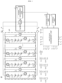
- FIG. 1 is a block diagram showing a configuration of an apparatus for controlling power of a parallel multi pack system according to an embodiment of the present disclosure.
- a power control apparatus 10 is a device for controlling a power of a parallel multi pack system MP in which a plurality of battery packs P1 to Pn are connected in parallel, and the power control apparatus 10 adaptively controls a total power (P total ) of the parallel multi pack system MP to prevent some of the battery packs having relatively low pack resistance from being overcharged or overdischarged.
- the parallel multi pack system MP is defined as a battery system including the first to n th battery packs P1 to Pn that are connected in parallel through first to n th switch units S1 to Sn.
- the parallel multi pack system MP may be connected to a load L through an external switch unit M.
- the external switch unit M includes an external high-potential switch M+ and an external low-potential switch M-.
- the external high-potential switch M+ and the external low-potential switch M- may be relay switches, but the present disclosure is not limited thereto.
- the parallel multi pack system MP is electrically connected to the load L. Conversely, when the external high-potential switch M+ and the external low-potential switch M- are turned off, the electrical connection between the parallel multi pack system MP and the load L is released.
- the power control apparatus 10 of the parallel multi pack system MP receives a control command for charging start, charging end, discharging start or discharging end from a control device that controls the load L, and controls turn-on or turn-off operation of the external switch unit M according to the control command.
- the parallel multi pack system MP may be mounted to an electric-driven vehicle E, but the present disclosure is not limited thereto.
- the electric-driven vehicle E refers to a vehicle that can be driven by a motor, such as an electric vehicle or a hybrid electric vehicle.
- the load L is a device that receives power from the parallel multi pack system MP, and may be an inverter included in an electric-driven vehicle E as an example.
- the inverter is a power conversion circuit that is installed at a front end of an electric motor of the electric-driven vehicle E to convert a DC current supplied from the parallel multi pack system MP into a 3-phase AC current and supplies the 3-phase AC current to the electric motor.
- the load L may also be a DC/DC converter.
- the DC/DC converter is a power conversion circuit that converts a voltage of a DC current supplied from the parallel multi pack system MP into a drive voltage of an electric equipment unit of the electric-driven vehicle E or a drive voltage of an ADAS unit and then applies the converted voltage to the electric equipment unit or the ADAS unit.
- the type of the load L is not limited to the inverter or the DC/DC converter, and any device or instrument capable of receiving power from the parallel multi pack system MP may be included in the category of the load L regardless of its type.
- each of the first to n th battery packs P1 to Pn includes a plurality of battery cells connected in series therein. That is, the first battery pack P1 includes first to p th battery cells C 11 to C 1p connected in series.
- the second battery pack P2 includes first to p th battery cells C 21 to C 2p connected in series.
- the third battery pack P3 includes first to p th battery cells C 31 to C 3p connected in series.
- the n th battery pack Pn includes first to p th battery cells C n1 to C np connected in series.
- each of the fourth to n-1 th battery packs also includes a p number of battery cells connected in series in the same manner as the illustrated battery packs.
- Each of the first to n th battery packs P1 to Pn includes the switch units S1 to Sn therein. That is, the first battery pack P1 includes a first switch unit S1. In addition, the second battery pack P2 includes a second switch unit S2. In addition, the third battery pack P3 includes a third switch unit S3. In addition, the n th battery pack Pn includes an n th switch unit Sn. Though the fourth to n-1 th battery packs are not shown in the drawing, each of the fourth to n-1 th battery packs also includes a switch unit in the same manner as the illustrated battery packs.
- Each of the first to n th switch units S1 to Sn includes a low-potential switch and a high-potential switch. That is, the first switch unit S1 includes a first high-potential switch S1 + installed at a high-potential side of the first battery pack P1 and a first low-potential switch S1 - installed at a low-potential side of the first battery pack P1.
- the second switch unit S2 includes a second high-potential switch S2 + installed at a high-potential side of the second battery pack P2 and a second low-potential switch S2 - installed at a low-potential side of the second battery pack P2.
- the third switch unit S3 includes a third high-potential switch S3 + installed at a high-potential side of the third battery pack P3 and a third low-potential switch S3 - installed at a low-potential side of the third battery pack P3.
- the n th switch unit Sn includes an n th high-potential switch Sn + installed at a high-potential side of the n th battery pack Pn and an n th low-potential switch Sn - installed at a low-potential side of the n th battery pack Pn.
- each of the fourth to n-1 th battery packs also includes a high-potential switch and a low-potential switch in the same manner as the illustrated battery pack.
- any one of the high-potential switch and the low-potential switch may be omitted.
- the low-potential switch when the switch unit is turned on, the low-potential switch may be turned on first and the high-potential switch may be turned on later. Also, when the switch unit is turned off, the high-potential switch may be turned off first and the low-potential switch may be turned off later.
- the switch employed at the switch units S1 to Sn may be relay switch.
- the switch units S1 to Sn may be a semiconductor switch such as a MOSFETor a power semiconductor switch, but the present disclosure is not limited thereto.
- a capacitor Cap is provided at a front end of the load L.
- the capacitor Cap is connected in parallel between the parallel multi pack system MP and the load L.
- the capacitor Cap functions as a filter to prevent a noise current from being applied toward the load L.
- the power control apparatus 10 includes first to n th current sensors I1 to In.
- the first to n th current sensors I1 to In are installed on power lines C1 to Cn connected to the first to n th battery packs P1 to Pn, respectively, to measure a current value flowing through the power lines C1 to Cn.
- the first current sensor I1 measures a first battery pack current value (I s1 ) flowing through the first power line C1 included in the first battery pack P1.
- the second current sensor I2 measures a second battery pack current value (I s2 ) flowing through the second power line C2 included in the second battery pack P2.
- the third current sensor I3 measures a third battery pack current value (I s3 ) flowing through the third power line C3 included in the third battery pack P3.
- the n th current sensor In measures an n th battery pack current value (I sn ) flowing through the n th power line Cn included in the n th battery pack Pn.
- the fourth to n-1 th current sensors measure current values flowing through the fourth to n-1 th power lines included in the fourth to n-1 th battery packs, respectively.
- first to n th current sensors I1 to In are included in the battery packs, respectively.
- the first to n th current sensors I1 to In may also be installed outside the battery packs, without limitation.
- the first to n th current sensors I1 to In may be Hall sensors.
- the Hall sensor is a known current sensor that outputs a voltage signal corresponding to the magnitude of a current.
- the first to n th current sensors I1 to In may be sense resistors. If the voltage applied to both ends of the sense resistor is measured, the magnitude of current flowing through the sense resistor may be determined using Ohm's law. In other words, if the magnitude of the measured voltage is divided by a known resistance value of the sense resistor, the magnitude of current flowing through the sense resistor may be determined.
- the power control apparatus 10 also includes first to n th voltage sensors V1 to Vn.
- the first voltage sensor V1 measures a first battery pack voltage value (V s1 ) corresponding to a potential difference between the positive electrode and the negative electrode of the first battery pack P1.
- the second voltage sensor V2 measures a second battery pack voltage value (V s2 ) corresponding to a potential difference between the positive electrode and the negative electrode of the second battery pack P2.
- the third voltage sensor V3 measures a third battery pack voltage value (V s3 ) corresponding to a potential difference between the positive electrode and the negative electrode of the third battery pack P3.
- the n th voltage sensor Vn measures an n th battery pack voltage value (V sn ) corresponding to a potential difference between the positive electrode and the negative electrode of the n th battery pack Pn.
- V sn battery pack voltage value
- the fourth to n-1 th voltage sensors measures fourth to n-1 th battery pack voltage values, respectively.
- the first to n th voltage sensors V1 to Vn include a voltage measurement circuit such as a differential amplifier circuit. Since the voltage measurement circuit is well known in the art, the voltage measurement circuit will not be described in detail here.
- the power control apparatus 10 also includes first to n th temperature sensors T1 to Tn.
- the first temperature sensor T1 measures a first battery pack temperature value (T s1 ) indicating a surface temperature of a cell located at a predetermined position, for example at a center, of the first battery pack P1.
- the second temperature sensor T2 measures a second battery pack temperature value (T s2 ) indicating a surface temperature of a cell located at a predetermined position, for example at a center, of the second battery pack P2.
- the third temperature sensor T3 measures a third battery pack temperature value (T s3 ) indicating a surface temperature of a cell located at a predetermined position, for example at a center, of the third battery pack P3.
- the n th temperature sensor Tn measures an n th battery pack temperature value (T sn ) indicating a surface temperature of a cell located at a predetermined position, for example at a center, of the n th battery pack Pn.
- the fourth to n-1 th temperature sensors measure fourth to n-1 th battery pack temperature values, respectively.
- the first current sensor I1, the first voltage sensor V1 and the first temperature sensor T1 constitute a first sensor unit SU1.
- the second current sensor I2, the second voltage sensor V2 and the second temperature sensor T2 constitute a second sensor unit SU2.
- third current sensor I3, the third voltage sensor V3 and the third temperature sensor T3 constitute a third sensor unit SU3.
- the n th current sensor In, the n th voltage sensor Vn and the n th temperature sensor Tn constitute an n th sensor unit SUn.
- the fourth to n-1 th sensor units also include a current sensor, a voltage sensor and a temperature sensor, respectively.
- first to n th sensor units SU1 to SUn may further include sensors for measuring other operating characteristics of the battery pack in addition to the sensors for measuring current, voltage and temperature.
- the power control apparatus 10 also includes a multi pack management unit 20 operatively coupled to a power management unit 40 and the first to n th sensor units SU1 to SUn, and preferably to the first to n th switch units S1 to Sn.
- the power management unit 40 of the electric-driven vehicle E manages the power consumed in the load L.
- the power management unit 40 may adaptively manage the magnitude of power consumed in the load L to be suitable for the total power of the parallel multi pack system MP.
- the total power means a total discharging power of the parallel multi pack system MP.
- the load L may be replaced with a charging device.
- the power management unit 40 may adaptively manage a charging power supplied to the parallel multi pack system MP to be suitable for the total power of the parallel multi pack system MP.
- total power means a total charging power provided to the parallel multi pack system MP.
- the power control apparatus 10 may further include a communication unit 30 interposed between the multi pack management unit 20 and the power management unit 40.
- the communication unit 30 forms a communication interface between the multi pack management unit 20 and the power management unit 40.
- any known communication interface that supports communication between two different communication media may be used as the communication interface.
- the communication interface may support wired or wireless communication.
- the communication interface may support CAN communication or daisy chain communication.
- the multi pack management unit 20 turns on the external switch unit M to initiate discharging of the parallel multi pack system MP.
- an M+ signal and an M- signal output from the multi pack management unit 20 represent signals that control the on/off operation of the external high-potential switch M+ and the external low-potential switch M-, respectively.
- S1 to Sn signals output from the multi pack management unit 20 represent signals that controls the on/off operation of the first to n th switch units S1 to Sn.
- the multi pack management unit 20 also controls the operation of the current sensors I1 to In, the voltage sensors V1 to Vn and the temperature sensors T1 to Tn included in the first to n th sensor units SU1 to SUn while the parallel multi pack system MP is being discharged, and periodically records the operation characteristic value of each battery pack received from the current sensors I1 to In, the voltage sensors V1 to Vn and the temperature sensors T1 to Tn in the storage unit 50.
- the operation characteristic value includes measured current values (I s1 to I sn ), measured voltage values (V s1 to V sn ) and measured temperature values (T s1 to T s2 ) of the first to n th battery packs P1 to Pn as shown in the figure.
- the multi pack management unit 20 may also determine a SOC (State Of Charge) of each battery pack based on the operation characteristic values of the first to n th battery packs P1 to Pn.
- SOC State Of Charge
- the multi pack management unit 20 may determine the SOC of the first to n th battery packs P1 to Pn by counting the measured current values (I s1 to I sn ) of the first to n th battery packs P1 to Pn over time.
- the multi pack management unit 20 may measure the OCV of each battery pack using the first to n th voltage sensors V1 to Vn before initiating the discharging of the first to n th battery packs P1 to Pn, and determine an initial SOC of each battery pack by referring to an OCV-SOC look-up table to look up a SOC corresponding to the OCV.
- the multi pack management unit 20 may count the measured current values (I s1 to I sn ) of the first to n th battery packs P1 to Pn based on the initial SOC over time and record the same in the storage unit 50.
- the OCV-SOC look-up table may be defined in advance and recorded in the storage unit 50.
- the multi pack management unit 20 may determine the SOC of the first to n th battery packs P1 to Pn using the extended Kalman filter while the parallel multi pack system MP is being discharged. That is, the multi pack management unit 20 may determine the SOC of the first to n th battery packs P1 to Pn by inputting the operation characteristic value of each battery pack received from the first to n th sensor units SU1 to SUn into the extended Kalman filter coded in software, and record the same in the storage unit 50.
- the extended Kalman filter is widely known in the technical field to which the present disclosure belongs.
- the extended Kalman filter may be an adaptive algorithm based on an equivalent circuit model or an electrochemical reduced order model (ROM).
- the SOC may be determined using other known methods capable of determining SOC by selectively utilizing the operation characteristic value of the battery pack, in addition to the current counting method or the extended Kalman filter described above.
- the multi pack management unit 20 may count a current value measured in a specific voltage range among a plurality of current values for each battery pack recorded in the storage unit 50.
- the multi pack management unit 20 may determine a SOH (State Of Health) of each battery pack by referring to a current count value-SOH look-up table in which SOH according to the counted current value of a specific voltage range is defined in advance.
- the multi pack management unit 20 may adaptively determine the SOH of the first to n th battery packs P1 to Pn using the extended Kalman filter while the parallel multi pack system MP is being discharged.
- the multi pack management unit 20 may determine the SOH of the first to n th battery packs P1 to Pn by inputting the operation characteristic value of each battery pack received from the first to n th sensor units SU1 to SUn into the extended Kalman filter coded in software.
- the SOH estimation using the extended Kalman filter is disclosed in, for example, Korean Patent Registration No. 10-0818520 , entitled “Apparatus, method, system and recording medium for estimating a current state and current parameters of an electrochemical cell", which may be incorporated as part of this specification.
- the multi pack management unit 20 may determine a pack resistance of each battery pack based on the operation characteristic values of the first to n th battery packs P1 to Pn and record the same in the storage unit 50.
- the multi pack management unit 20 may determine an I-V profile for each battery pack by means of linear regression analysis by using a plurality of measured current values and a plurality of measured voltage values for each battery pack recorded in the storage unit 50 while the parallel multi pack system MP is being discharged.
- the plurality of measured current values and the plurality of measured voltage values are sampled for recent measured values based on a present time point.
- the multi pack management unit 20 may determine a slope of the I-V profile, calculate an absolute value of the slope as the pack resistance for each battery pack, and record the same in the storage unit 50.
- the multi pack management unit 20 may refer to the present measured temperature value and SOC for each battery pack recorded in the storage unit 50 while the parallel multi pack system MP is being discharged to determine a pack resistance corresponding to the measured temperature value and SOC by looking up a SOC-temperature-pack resistance look-up table, and record the same in the storage unit 50.
- the SOC-temperature-pack resistance look-up table has a data structure capable of looking up the pack resistance corresponding to SOC and temperature, and the SOC-temperature-pack resistance look-up table may be defined in advance and recorded in the storage unit 50.
- the multi pack management unit 20 also determines an n number of available powers corresponding to the pack resistance of each battery pack by using pre-defined correlation information between pack resistance and available power, and determines a minimum available power among the n number of available powers.
- the pre-defined correlation may be a pack resistance-available power look-up table capable of looking up the available power according to the pack resistance.
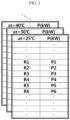
- FIG. 2 is a diagram showing an example of a pack resistance-available power look-up table according to an embodiment of the present disclosure.
- the pack resistance-available power look-up table has a data structure capable of looking up the available power using the pack resistance, and may be defined in advance and recorded in the storage unit 50. It is preferable that the pack resistance-available power look-up table is provided independently according to the temperature of the battery pack. In this case, it may be considered that the available power varies according to the temperature of the battery pack.
- the multi pack management unit 20 may identify the pack resistance-available power look-up table that is to be looked up using the measured temperature value of each battery pack, and determine the available power corresponding to the pack resistance using the identified look-up table.
- the pack resistance-available power look-up table may be provided independently for each SOH and temperature of the battery pack. In this case, it may be considered that the available power varies according to the temperature and SOH of the battery pack.
- the multi pack management unit 20 may identify the pack resistance-available power look-up table that is to be looked up using the measured temperature value and SOH of each battery pack, and determine the available power corresponding to the pack resistance using the identified look-up table.
- the multi pack management unit 20 may determine the available power for each battery pack using the I-V profile generated when determining the pack resistance of each battery pack.
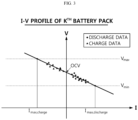
- FIG. 3 is a graph showing an example of an I-V profile in determining a pack resistance of a battery pack according to an embodiment of the present disclosure.
- the voltage at an intersection point where the I-V profile meets a V axis is the OCV corresponding to the SOC of the battery pack.
- Dot marks indicate a plurality of measured voltage values and a plurality of measured current values measured when the parallel multi pack system MP is being discharged.
- the I-V profile is a straight line generated by means of linear regression analysis for the plurality of measured voltage values and the plurality of measured current values.
- the measured current value is a positive value
- the measured current value is a negative value.
- the absolute value of the slope of the I-V profile corresponds to the pack resistance of the battery pack.
- diamond marks are coordinates representing the plurality of measured voltage values and the plurality of measured current values measured when the parallel multi pack system MP is being discharged.
- triangle marks are coordinates representing the plurality of measured voltage values and the plurality of measured current values measured when the parallel multi pack system MP is being charged.
- the multi pack management unit 20 determines the available powers of the first to n th battery packs P1 to Pn, then determines a minimum available power among the n number of available powers, and records the same in the storage unit 50.
- the multi pack management unit 20 also determines the total power of the parallel multi pack system MP so that the pack power of the battery pack having the lowest pack resistance is identical to the minimum available power, and records the same in the storage unit 50.
- the multi pack management unit 20 may determine the total power of the parallel multi pack system MP using Equation 1 below.
- P total min P pack , k * min R pack , k / R system
- R system ⁇ 1 / R pack , k ⁇ 1
- k is an integer from 1 to n.
- Equation 1 may be converted into an equation including the total power term "min(P pack,k )*n", which is determined according to the prior art, as in Equation 2 below.
- min(R pack,k )/ ⁇ [min(P pack,k )*n]*R system corresponds to a reciprocal of a pack power calculated by the prior art for the battery pack having the lowest resistance among the first to n th battery packs P1 to Pn.
- the total power of the parallel multi pack system MP calculated according to the prior art is "min(P pack,k )*n", which is obtained by multiplying the minimum value "min(P pack,k )" among the pack powers by the number n of battery packs, and the pack power of the battery pack having the lowest resistance corresponds to a value obtained by multiplying a resistance ratio "R system /min(R pack,k )" by the total power "min(P pack,k )*n" calculated by the prior art.
- the total power (P total ) of the parallel multi pack system MP determined according to the present disclosure corresponds to a value obtained by multiplying the total power "min(P pack,k )*n" determined according to the prior art by an attenuation factor, namely "min(P pack,k )/max(P pack,k )".
- min(P pack,k )/max(P pack,k ) is a relative ratio between a maximum value and a minimum value among the pack powers and thus is always smaller than 1.
- the total power of the parallel multi pack system MP determined according to the present disclosure is smaller than the total power determined according to the prior art by [min(P pack,k )*n]*[1-min(P pack,k )/max(P pack,k ).
- the multi pack management unit 20 may transmit information on the total power (P total ) to the power management unit 40 of the electric-driven vehicle E through the communication unit 30.
- the power management unit 40 controls charging or discharging of the parallel multi pack system MP so that the power of the parallel multi pack system MP does not exceed the total power (P total ) determined by Equation 1. That is, the power management unit 40 controls the power consumption so that the power consumed in the load L does not exceed the total power (P total ) determined by Equation 1.
- the power management unit 40 adaptively distributes the power supplied to an inverter or a DC/DC converter corresponding to the load L and the power supplied to an electrical equipment unit and an ADAS (Advanced Driver Assistance System) unit, which supports functions of lane departure prevention, front collision warning or the like, so as not to exceed the total power (P total ) of the parallel multi pack system MP.
- ADAS Advanced Driver Assistance System
- the power management unit 40 may adaptively adjust the magnitude of the charging voltage and the charging current provided to the parallel multi pack system MP so as not to exceed the total power (P total ) determined by Equation 1 while the parallel multi pack system MP is being charged using the charging device.
- the multi pack management unit 20 may be configured to calculate the pack power (P pack,k ) of each battery pack using Equation 4 below.
- P pack , k P total * R system / R pack , k (P pack,k is the pack power of the k th battery pack; P total is the total power of the parallel multi pack system; R system is the total resistance of the parallel multi pack system; and R pack,k is the pack resistance of the k th battery pack)
- the first to n th battery packs P1 to Pn are connected in parallel. Therefore, when the present power of the parallel multi pack system MP is P total , the pack power (P pack,k ) of each battery pack corresponds to the value calculated by the above equation.
- the type of the storage unit 50 is a storage medium capable of recording and erasing information.
- the storage unit 50 may be a RAM, a ROM, an EEPROM, a register, or a flash memory.
- the storage unit 50 may also be electrically connected to the multi pack management unit 20 through, for example, a data bus so as to be accessed by the multi pack management unit 20.
- the storage unit 50 also stores and/or updates and/or erases and/or transmits a program including various control logics performed by the multi pack management unit 20, and/or data generated when the control logic is executed and look-up tables and parameters defined in advance.
- the storage unit 50 may be logically divided into two or more parts and may be included in the multi pack management unit 20 without limitation.
- the multi pack management unit 20 and/or the power management unit 40 may optionally include a processor, an application-specific integrated circuit (ASIC), another chipset, a logic circuit, a register, a communication modem, a data processing device, or the like, known in the art to execute the various control logics described above.
- the control logic when the control logic is implemented in software, the multi pack management unit 20 and/or the power management unit 40 may be implemented as a set of program modules.
- the program module may be stored in a memory and executed by a processor.
- the memory may be provided inside or outside the processor and be connected to the processor through various well-known computer components. Also, the memory may be included in the storage unit 50.
- the memory refers to a device in which information is stored, regardless of the type of device, and does not refer to a specific memory device.
- one or more of the various control logics of the multi pack management unit 20 and/or the power management unit 40 may be combined, and the combined control logics may be written in a computer-readable code system and recorded in a computer-readable recording medium.
- the recording medium is not particularly limited as long as it is accessible by a processor included in a computer.
- the storage medium includes at least one selected from the group consisting of a ROM, a RAM, a register, a CD-ROM, a magnetic tape, a hard disk, a floppy disk and an optical data recording device.
- the code scheme may be distributed to a networked computer to be stored and executed therein.
- functional programs, codes and code segments for implementing the combined control logics may be easily inferred by programmers in the art to which the present disclosure belongs.
- the power control apparatus 10 may be included in a battery management system 100 as shown in FIG. 6 .
- the battery management system 100 controls the overall operation related to charging and discharging of a battery, and is a computing system called a battery management system (BMS) in the art.
- BMS battery management system
- the power control apparatus 10 may be mounted to various types of electric driving mechanism 200 as shown in FIG. 7 , in addition to the electric-driven vehicle E.
- the electric driving mechanism 200 may be an electric power device movable by electricity, such as an electric bicycle, an electric motorcycle, an electric train, an electric ship and an electric plane, or a power tool having a motor, such as an electric drill and an electric grinder.
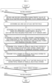
- FIG. 4 is a flowchart for illustrating a method for controlling power of a parallel multi pack system according to an embodiment of the present disclosure.
- Step S10 the multi pack management unit 20 determines whether the parallel multi pack system MP is in a discharge state. To this end, the multi pack management unit 20 may monitor current values measured using the first to n th current sensors I1 to In. If the current values are positive rather than 0, it may be determined that the parallel multi pack system MP is being discharged. If the determination result of Step S10 is YES, the multi pack management unit 20 proceeds to Step S20.
- Step S20 the multi pack management unit 20 controls the first to n th sensor units SU1 to SUn to receive the operation characteristic values of the first to n th battery packs P1 to Pn from the first to n th sensor units SU1 to SUn, and records the same in the storage unit 50.
- the operation characteristic value includes a measured voltage value, a measured current value and a measured temperature value of each battery pack. Step S30 proceeds after Step S20.
- Step S30 the multi pack management unit 20 determines SOC and SOH of each battery pack.
- the method of determining SOC and SOH has already been described above.
- Step S40 proceeds after Step S30.
- Step S40 the multi pack management unit 20 determines the pack resistances of the first to n th battery packs P1 to Pn, respectively, based on the operation characteristic value of each battery pack received from the first to n th sensor units SU1 to SUn.
- the multi pack management unit 20 may generate an I-V profile for a plurality of measured voltage values and a plurality of measured current values recently sampled based on the present time point by means of linear regression analysis, and calculate the pack resistance of each battery pack from a slope of the I-V profile.
- Step S50 proceeds after Step S40.
- Step S50 the multi pack management unit 20 determines an n number of available powers corresponding to the pack resistance of each battery pack using a pre-defined correlation between pack resistance and available power, and determines a minimum available power among the n number of available powers.
- the multi pack management unit 20 may look up an available power corresponding to the pack resistance of each battery pack using the pack resistance-available power look-up table recorded in advance in the storage unit 50.
- the multi pack management unit 20 may determine the available power by identifying the pack resistance-available power look-up table corresponding to the measured temperature value and SOH of the corresponding battery pack and looking up an available power corresponding to the pack resistance using the identified pack resistance-available power look-up table.
- Step S60 the multi pack management unit 20 determines the total power (P total ) of the parallel multi pack system so that the pack power of the battery pack having the lowest pack resistance is identical to the minimum available power using Equation 1 above.
- Step S70 proceeds after Step S60.
- the total power P total has a magnitude attenuated by [min(P pack,k )*n]*[1-min(P pack,k )/max(P pack,k )] compared to the total power calculated according to the prior art.
- Step S70 the multi pack management unit 20 transmits the total power (P total ) of the parallel multi pack system MP to the power management unit 40 of the electric-driven vehicle E through the communication unit 30.
- Step S80 proceeds after Step S70.
- Step S80 the power management unit 40 controls discharging of the parallel multi pack system MP so that the power of the parallel multi pack system MP does not exceed the total power (P total ) determined by Equation 1.
- the power management unit 40 controls the power consumption so that the power consumed in the load L does not exceed the total power (P total ) determined by Equation 1.
- the power management unit 40 adaptively distributes the power supplied to an inverter or a DC/DC converter corresponding to the load L and the power supplied to an electrical equipment unit and an ADAS (Advanced Driver Assistance System) unit, which supports functions of lane departure prevention, front collision warning or the like, so as not to exceed the total power (P total ) of the parallel multi pack system MP.
- ADAS Advanced Driver Assistance System
- Step S90 proceeds after Step S80.
- Step S90 the multi pack management unit 20 determines whether a preset power adjustment period passes.
- the power adjustment period is several ten msec to several seconds. If the determination result of Step S90 is NO, the multi pack management unit 20 holds progression of the process. Meanwhile, if the determination result of Step S90 is YES, the multi pack management unit 20 proceeds to S 100.
- Step S100 the multi pack management unit 20 determines whether the parallel multi pack system MP is being discharged. To this end, the multi pack management unit 20 may monitor the measured current values measured using the first to n th current sensors I1 to In. If the measured current values are positive rather than 0, it may be determined that the parallel multi pack system MP is being discharged.
- Step S 100 If the determination result of Step S 100 is NO, the multi pack management unit 20 ends the execution of the power control method according to an embodiment of the present disclosure. Meanwhile, if the determination result of Step S100 is YES, the multi pack management unit 20 proceeds to Step S20. Therefore, the process of calculating the total power (P total ) of the parallel multi pack system MP and the process of controlling the discharging of the parallel multi pack system MP so as not to exceed the calculated total power (P total ) are repeated again.
- FIG. 5 is a table comparatively showing results of an embodiment where the method for controlling power of a parallel multi pack system according to the present disclosure is applied and a comparative example where the prior art is applied together.
- a parallel multi pack system including 5 battery packs (Pack1 to Pack5) connected in parallel was prepared. Then, while the parallel multi pack system is being discharged at 25 ⁇ C, the total power of the parallel multi pack system and the power of each battery pack were calculated at a specific time point using the present disclosure and the prior art.
- the resistances of Pack1 to Pack5 were calculated as 120 m ⁇ , 110 m ⁇ , 100 m ⁇ , 90 m ⁇ and 80 m ⁇ , respectively.
- the SOHs of Pack1 to Pack5 were calculated as 0.94, 0.95, 0.96, 0.97 and 0.98, respectively.
- the available powers of Pack1 to Pack5 looked up from the pack resistance-available power look-up table identified by temperature and SOH were determined as 94 kW, 95 kW, 96 kW, 97 kW and 98 kW, respectively.
- the total power (P' total ) of the parallel multi pack system MP is "min(P pack,k )*5", which becomes 470 kW if 94 kW is put into min(P pack,k ).
- the pack power (P' pack,k ) of each battery pack is calculated by the equation P' tota l*R system /R pack,k . Therefore, the pack powers of Pack1 to Pack5 are 76.7 kW, 83.7 kW, 92.1 kW, 102.3 kW and 115.1 kW, respectively.
- the pack powers of Pack4 and Pack5 are greater than the available power. Therefore, if the total power (P' total ) of the parallel multi pack system MP is calculated according to the prior art and then the discharging of the parallel multi pack system MP is controlled accordingly, Pack4 and Pack5 are overdischarged.
- the total power (P total ) of the parallel multi pack system MP is calculated by the equation min(P pack,k )*min(R pack,k )/R system .
- min(P pack,k ) is 94 kW because it is a minimum value among the available powers.
- min(R pack,k ) is 80 m ⁇ because it is a minimum value among the pack resistances.
- R system is 19.6 m ⁇ . If the value of each factor is put into the equation, the total power (P total ) of the parallel multi pack system MP is determined as 383.8 kW.
- the pack power (P pack,k ) of each battery pack is calculated by the equation P total *R system /R pack,k in the same way as in the prior art.
- the pack powers of Pack1 to Pack5 are 62.7 kW, 68.4 kW, 75.2 kW, 83.6 kW and 94.0 kW, respectively.
- the total power is calculated according to the present disclosure, even a battery pack (Pack4, Pack5) with a relatively low resistance has a pack power lower than the available power. Therefore, the problem that the battery pack having a low resistance is overdischarged while the parallel multi pack system MP is being discharged does not occur.
- the total power of the parallel multi pack system is adjusted so that the pack power of the battery pack having the lowest resistance among the battery packs included in the parallel multi pack system becomes identical to a minimum available power among available powers of the battery packs, thereby fundamentally preventing the battery pack having a low resistance from being overcharged or overdischarged.
- safety and reliability of the parallel multi pack system may be improved compared to the prior art.
- each element may be selectively integrated with other elements or each element may be divided into sub-elements for effective implementation control logic (s).
- each element may be selectively integrated with other elements or each element may be divided into sub-elements for effective implementation control logic (s).
- functional identity can be acknowledged for the integrated or divided elements, the integrated or divided elements fall within the scope of the present disclosure.
Landscapes
- Engineering & Computer Science (AREA)
- Power Engineering (AREA)
- Life Sciences & Earth Sciences (AREA)
- Mechanical Engineering (AREA)
- Transportation (AREA)
- Sustainable Energy (AREA)
- Sustainable Development (AREA)
- Chemical & Material Sciences (AREA)
- General Chemical & Material Sciences (AREA)
- Electrochemistry (AREA)
- Chemical Kinetics & Catalysis (AREA)
- Manufacturing & Machinery (AREA)
- Charge And Discharge Circuits For Batteries Or The Like (AREA)
- Secondary Cells (AREA)
Claims (14)
- Vorrichtung (10) zur Leistungssteuerung eines parallelen Multipacksystems (MP), wobei die Vorrichtung aufweist:erste bis n-te Sensoreinheiten (SU1... S4n), die konfiguriert sind, um Betriebskennwerte von ersten bis n-ten Batteriepacks (P1...Pn) zu messen, die in dem parallelen Multipacksystem (MP) enthalten sind und parallel miteinander verbunden sind;Leistungsverwaltungseinheit (40), die konfiguriert ist, um eine in einer Last (L) verbrauchte Leistung oder eine von einer Ladevorrichtung gelieferte Leistung so zu steuern, dass sie einer Gesamtleistung des parallelen Multipacksystems entspricht; undeine Multipack-Verwaltungseinheit (20), die mit den ersten bis n-ten Sensoreinheiten und der Leistungsverwaltungseinheit betriebsmäßig verbunden ist,wobei die Multipack-Verwaltungseinheit konfiguriert ist, um einen Packwiderstand von jedem der ersten bis n-ten Batteriepacks basierend auf dem von den ersten bis n-ten Sensoreinheiten empfangenen Betriebskennwert jedes Batteriepacks zu bestimmen, eine verfügbare Minimalleistung unter verfügbaren Leistungen, die jeweils den Packwiderständen der Batteriepacks entsprechen, mittels einer vordefinierten Korrelationsinformation zwischen dem Packwiderstand und der verfügbaren Leistung zu bestimmen, die Gesamtleistung des parallelen Multipacksystems so zu bestimmen, dass die Packleistung eines Batteriepacks mit dem niedrigsten Packwiderstand identisch mit der verfügbaren Minimalleistung wird, und die bestimmte Gesamtleistung des parallelen Multipacksystems zu der Leistungsverwaltungseinheit zu senden, unddie Leistungssteuerungseinheit konfiguriert ist, um die in der Last verbrauchte Leistung oder die von der Ladevorrichtung gelieferte Leistung so zu steuern, dass sie die Gesamtleistung des parallelen Multipacksystems nicht überschreitet.
- Die Vorrichtung zur Leistungssteuerung eines parallelen Multipacksystems nach Anspruch 1,
wobei die Korrelationsinformation eine Packwiderstand-Verfügbare-Leistung-Nachschlagetabelle ist, in der die verfügbare Leistung des Batteriepacks gemäß dem Packwiderstand des Batteriepacks definiert ist. - Die Vorrichtung zur Leistungssteuerung eines parallelen Multipacksystems nach Anspruch 1,
wobei die Multipack-Verwaltungseinheit konfiguriert ist zum:periodischen Empfangen eines gemessenen Spannungswerts und eines gemessenen Stromwerts jedes Batteriepacks von den ersten bis n-ten Sensoreinheiten, undBestimmen des Packwiderstands jedes Batteriepacks durch Analyse der Mehrzahl gemessener Spannungswerte und der Mehrzahl gemessener Stromwerte mittels linearer Regressionsanalyse. - Die Vorrichtung zur Leistungssteuerung eines parallelen Multipacksystems nach Anspruch 1,wobei die Multipack-Verwaltungseinheit konfiguriert ist, um die Gesamtleistung des parallelen Multipacksystems mittels der folgenden Gleichung zu berechnen:

 wobei k eine ganze Zahl von 1 bis n ist; n die Anzahl von Batteriepacks ist; Ptotal die Gesamtleistung des parallelen Multipacksystems ist; Ppack,k eine Packleistung eines k-ten Batteriepacks ist; Rpack,k ein Packwiderstand des k-ten Batteriepacks ist; Rsystem ein Gesamtwiderstand des parallelen Multipacksystems ist; und min() eine Funktion ist, die, unter einer Mehrzahl eingegebener Variablen, zu einem Minimalwert zurückkehrt.
 - Die Vorrichtung zur Leistungssteuerung eines parallelen Multipacksystems nach Anspruch 4,wobei die Multipack-Verwaltungseinheit konfiguriert ist, um die Packleistung jedes Batteriepacks mittels der folgenden Gleichung zu berechnen:
 wobei Ppack,k die Packleistung des k-ten Batteriepacks ist; Ptotal die Gesamtleistung des parallelen Multipacksystems ist; Rsystem der Gesamtwiderstand des parallelen Multipacksystems ist; und Rpack,k ist der Packwiderstand des k-ten Batteriepacks ist.
 - Die Vorrichtung zur Leistungssteuerung eines parallelen Multipacksystems nach Anspruch 1, die ferner aufweist:
eine Kommunikationseinheit (30), die zwischen der Multipack-Verwaltungseinheit und der Leistungsverwaltungseinheit eingefügt ist. - Die Vorrichtung zur Leistungssteuerung eines parallelen Multipacksystems nach Anspruch 6,wobei das parallele Multipacksystem an einem elektrisch angetriebenen Fahrzeug angebracht ist, unddie Leistungsverwaltungseinheit in einem Steuersystem des elektrisch angetriebenen Fahrzeugs enthalten ist.
- Batterieverwaltungssystem (100), das die Vorrichtung zur Leistungssteuerung eines parallelen Multipacksystems nach Anspruch 1 aufweist.
- Elektrischer Antriebsmechanismus (200), der die Vorrichtung zur Leistungssteuerung eines parallelen Multipacksystems nach Anspruch 1 aufweist.
- Verfahren zur Leistungssteuerung eines parallelen Multipacksystems (MP), welches aufweist:(a) Bereitstellen von ersten bis n-ten Sensoreinheiten, die konfiguriert sind, um die Betriebskennwerte von ersten bis n-ten Batteriepacks zu messen, die in dem parallelen Multipacksystem enthalten sind und parallel miteinander verbunden sind,(b) Bestimmen eines Packwiderstands von jedem der ersten bis n-ten Batteriepacks basierend auf dem von den ersten bis zur n-ten Sensoreinheiten empfangenen Betriebskennwert jedes Batteriepacks;(c) Bestimmen einer Anzahl n verfügbarer Leistungen, die jeweils den Packwiderständen der Batteriepacks entsprechen, mittels vordefinierter Korrelationsinformation zwischen dem Packwiderstand und der verfügbaren Leistung, und einer verfügbaren Minimalleistung davon;(d) Bestimmen der Gesamtleistung des parallelen Multipacksystems derart, dass die Packleistung eines Batteriepacks mit dem niedrigsten Packwiderstand mit der verfügbaren Minimalleistung identisch wird; und(e) Steuern von Laden oder Entladen der ersten bis n-ten Batteriepacks derart, dass die Gesamtleistung des parallelen Multipacksystems nicht überschritten wird.
- Das Verfahren zur Leistungssteuerung eines parallelen Multipacksystems nach Anspruch 10,
wobei die Korrelationsinformation eine Packwiderstand-Verfügbare-Leistung-Nachschlagetabelle ist, in der die verfügbare Leistung des Batteriepacks gemäß dem Packwiderstand des Batteriepacks definiert ist. - Das Verfahren zur Leistungssteuerung eines parallelen Multipacksystems nach Anspruch 10,
wobei der Schritt (b) enthält:(b1) periodisches Empfangen eines gemessenen Spannungswerts und eines gemessenen Stromwerts jedes Batteriepacks von den ersten bis n-ten Sensoreinheiten; und(b2) Bestimmen des Packwiderstands jedes Batteriepacks durch Analyse der Mehrzahl gemessener Spannungswerte und der Mehrzahl gemessener Stromwerte mittels linearer Regressionsanalyse. - Das Verfahren zur Leistungssteuerung eines parallelen Multipacksystems nach Anspruch 10, wobei in Schritt (d)die Gesamtleistung des parallelen Multipacksystems mittels der folgenden Gleichung berechnet wird:

 wobei k eine ganze Zahl von 1 bis n ist; n die Anzahl von Batteriepacks ist; Ptotal die Gesamtleistung des parallelen Multipacksystems ist; Ppack,k eine Packleistung eines k-ten Batteriepacks ist; Rpack,k ein Packwiderstand des k-ten Batteriepacks ist; Rsystem ein Gesamtwiderstand des parallelen Multipacksystems ist; und min() eine Funktion ist, die, unter einer Mehrzahl eingegebener Variablen, zu einem Minimalwert zurückkehrt.
 - Das Verfahren zur Leistungssteuerung eines parallelen Multipacksystems nach Anspruch 10,wobei in Schritt (e) die Packleistung jedes Batteriepacks mittels der folgenden Gleichung berechnet wird:
 wobei Ppack,k die Packleistung des k-ten Batteriepacks ist; Ptotal die Gesamtleistung des parallelen Multipacksystems ist; Rsystem der Gesamtwiderstand des parallelen Multipacksystems ist; und Rpack,k ist der Packwiderstand des k-ten Batteriepacks ist.
Applications Claiming Priority (2)
| Application Number | Priority Date | Filing Date | Title |
|---|---|---|---|
| KR1020190136953A KR102680305B1 (ko) | 2019-10-30 | 2019-10-30 | 병렬 멀티 팩 시스템의 출력 제어 장치 및 방법 |
| PCT/KR2020/014115 WO2021085901A1 (ko) | 2019-10-30 | 2020-10-15 | 병렬 멀티 팩 시스템의 출력 제어 장치 및 방법 |
Publications (3)
| Publication Number | Publication Date |
|---|---|
| EP3974247A1 EP3974247A1 (de) | 2022-03-30 |
| EP3974247A4 EP3974247A4 (de) | 2022-10-19 |
| EP3974247B1 true EP3974247B1 (de) | 2025-06-04 |
Family
ID=75716420
Family Applications (1)
| Application Number | Title | Priority Date | Filing Date |
|---|---|---|---|
| EP20881117.4A Active EP3974247B1 (de) | 2019-10-30 | 2020-10-15 | Vorrichtung und verfahren zur leistungssteuerung eines parallelen multipack-systems |
Country Status (9)
| Country | Link |
|---|---|
| US (1) | US11870292B2 (de) |
| EP (1) | EP3974247B1 (de) |
| JP (1) | JP7215657B2 (de) |
| KR (1) | KR102680305B1 (de) |
| CN (1) | CN113785464B (de) |
| ES (1) | ES3033820T3 (de) |
| HU (1) | HUE071832T2 (de) |
| PL (1) | PL3974247T3 (de) |
| WO (1) | WO2021085901A1 (de) |
Families Citing this family (3)
| Publication number | Priority date | Publication date | Assignee | Title |
|---|---|---|---|---|
| JP7364162B2 (ja) * | 2020-07-21 | 2023-10-18 | エルジー エナジー ソリューション リミテッド | 並列マルチパックモジュールの出力制御装置及び方法 |
| EP4435997A1 (de) * | 2023-03-23 | 2024-09-25 | Andreas Stihl AG & Co. KG | Verfahren und system zum betreiben eines elektrisch angetriebenen bearbeitungsgeräts mit mindestens einem akkupack, elektrisch angetriebenes bearbeitungsgerät und/oder akkupack |
| US20250132577A1 (en) * | 2023-10-20 | 2025-04-24 | Caterpillar Inc. | Scalable battery system and method |
Family Cites Families (31)
| Publication number | Priority date | Publication date | Assignee | Title |
|---|---|---|---|---|
| US6160381A (en) * | 1998-05-21 | 2000-12-12 | Qualcomm Inc. | Battery pack protection circuit and battery pack including a protection circuit |
| JP3872758B2 (ja) * | 2003-01-08 | 2007-01-24 | 株式会社日立製作所 | 電源制御装置 |
| US8103485B2 (en) | 2004-11-11 | 2012-01-24 | Lg Chem, Ltd. | State and parameter estimation for an electrochemical cell |
| JP4961830B2 (ja) * | 2006-05-15 | 2012-06-27 | トヨタ自動車株式会社 | 蓄電装置の充放電制御装置および充放電制御方法ならびに電動車両 |
| JP4782072B2 (ja) * | 2007-05-18 | 2011-09-28 | パナソニック株式会社 | 電源装置 |
| JP5163542B2 (ja) * | 2009-03-03 | 2013-03-13 | 日産自動車株式会社 | 二次電池の入出力可能電力推定装置 |
| DE102009049589A1 (de) | 2009-10-16 | 2011-04-21 | Bayerische Motoren Werke Aktiengesellschaft | Verfahren zur Bestimmung und/oder Vorhersage der maximalen Leistungsfähigkeit einer Batterie |
| JP5517692B2 (ja) * | 2010-03-26 | 2014-06-11 | 三菱重工業株式会社 | 電池パックおよび電池制御システム |
| JP5640474B2 (ja) * | 2010-06-07 | 2014-12-17 | ソニー株式会社 | 電池システム |
| JP5842421B2 (ja) | 2010-07-20 | 2016-01-13 | 日産自動車株式会社 | 電池状態推定装置 |
| JP5585308B2 (ja) | 2010-08-26 | 2014-09-10 | 日産自動車株式会社 | 電池制御装置 |
| JPWO2012132246A1 (ja) * | 2011-03-31 | 2014-07-24 | パナソニック株式会社 | 電池電源装置、及び電池電源システム |
| WO2013066867A2 (en) * | 2011-10-31 | 2013-05-10 | Cobasys, Llc | Parallel configuration of series cells with semiconductor switching |
| KR101549906B1 (ko) | 2013-04-30 | 2015-09-03 | 한국화학연구원 | 리튬이차전지의 상온에서의 수명예측방법 |
| KR101748642B1 (ko) | 2014-10-31 | 2017-06-19 | 주식회사 엘지화학 | 이차 전지의 출력 조정 장치 및 방법 |
| KR101846642B1 (ko) * | 2015-02-02 | 2018-04-06 | 주식회사 엘지화학 | 이차 전지의 저항 팩터 결정 방법, 상기 저항 팩터를 이용한 충전 출력 추정 장치 및 방법 |
| DE102015002148A1 (de) * | 2015-02-18 | 2016-08-18 | Audi Ag | Verfahren zum Betreiben von Batteriezellen einer Batterie, Batterie sowie Kraftfahrzeug |
| JP2017060316A (ja) | 2015-09-17 | 2017-03-23 | 積水化学工業株式会社 | 電力管理システム及び電力管理方法 |
| KR101876733B1 (ko) * | 2016-02-16 | 2018-07-10 | 현대자동차주식회사 | 연료 전지 차량용 고전압 배터리의 출력 제어 방법 및 장치 |
| JP2019114324A (ja) | 2016-03-28 | 2019-07-11 | 株式会社日立製作所 | 二次電池システム |
| US10608445B2 (en) * | 2016-09-21 | 2020-03-31 | Envision Aesc Japan Ltd. | Power supply system |
| KR102066703B1 (ko) * | 2017-01-24 | 2020-01-15 | 주식회사 엘지화학 | 배터리 관리 장치 및 방법 |
| KR102157882B1 (ko) * | 2017-07-19 | 2020-09-18 | 주식회사 엘지화학 | 무선 배터리 관리 시스템 및 이를 포함하는 배터리팩 |
| KR102373449B1 (ko) * | 2018-02-01 | 2022-03-10 | 주식회사 엘지에너지솔루션 | 배터리의 전력 한계 결정 방법 및 배터리 관리 시스템 |
| US10723295B2 (en) * | 2018-03-15 | 2020-07-28 | Thermo King Corporation | Methods and systems for managing bi-directional converter based battery modules |
| KR102361334B1 (ko) * | 2018-05-09 | 2022-02-09 | 주식회사 엘지에너지솔루션 | 배터리 제어 장치 및 이를 포함하는 에너지 저장 시스템 |
| JP7034834B2 (ja) | 2018-05-30 | 2022-03-14 | ルネサスエレクトロニクス株式会社 | 半導体装置およびその製造方法 |
| WO2020111899A1 (ko) * | 2018-11-30 | 2020-06-04 | 주식회사 엘지화학 | 스위치 제어 장치 및 방법 |
| US10988049B2 (en) * | 2019-05-16 | 2021-04-27 | GM Global Technology Operations LLC | Power management of high-current fast-charging battery |
| AU2020207822A1 (en) * | 2019-07-24 | 2021-02-11 | Tusimple, Inc. | Battery power control in autonomous vehicles having alternator-charging systems |
| JP7364162B2 (ja) * | 2020-07-21 | 2023-10-18 | エルジー エナジー ソリューション リミテッド | 並列マルチパックモジュールの出力制御装置及び方法 |
-
2019
- 2019-10-30 KR KR1020190136953A patent/KR102680305B1/ko active Active
-
2020
- 2020-10-15 EP EP20881117.4A patent/EP3974247B1/de active Active
- 2020-10-15 US US17/610,371 patent/US11870292B2/en active Active
- 2020-10-15 WO PCT/KR2020/014115 patent/WO2021085901A1/ko not_active Ceased
- 2020-10-15 HU HUE20881117A patent/HUE071832T2/hu unknown
- 2020-10-15 PL PL20881117.4T patent/PL3974247T3/pl unknown
- 2020-10-15 JP JP2021549506A patent/JP7215657B2/ja active Active
- 2020-10-15 ES ES20881117T patent/ES3033820T3/es active Active
- 2020-10-15 CN CN202080032411.2A patent/CN113785464B/zh active Active
Also Published As
| Publication number | Publication date |
|---|---|
| JP2022523931A (ja) | 2022-04-27 |
| US20220224138A1 (en) | 2022-07-14 |
| HUE071832T2 (hu) | 2025-09-28 |
| EP3974247A1 (de) | 2022-03-30 |
| EP3974247A4 (de) | 2022-10-19 |
| KR20210051538A (ko) | 2021-05-10 |
| CN113785464A (zh) | 2021-12-10 |
| US11870292B2 (en) | 2024-01-09 |
| WO2021085901A1 (ko) | 2021-05-06 |
| ES3033820T3 (en) | 2025-08-08 |
| JP7215657B2 (ja) | 2023-01-31 |
| KR102680305B1 (ko) | 2024-06-28 |
| PL3974247T3 (pl) | 2025-08-11 |
| CN113785464B (zh) | 2024-01-12 |
Similar Documents
| Publication | Publication Date | Title |
|---|---|---|
| EP4145667B1 (de) | Vorrichtung und verfahren zur steuerung der ausgabe eines parallelen mehrstückmoduls | |
| EP3982507B1 (de) | Vorrichtung und verfahren zum auswuchten von parallel geschalteten batteriepacks | |
| EP3605127B1 (de) | Vorrichtung und verfahren zur schätzung des batteriewiderstands | |
| EP2801837B1 (de) | Vorrichtung und verfahren zur messung des isolationswiderstands einer batterie | |
| EP3832326B1 (de) | Vorrichtung zur diagnose eines batteriepacks | |
| EP3985403B1 (de) | Vorrichtung und verfahren zur diagnose eines fehlers einer in einem multibatteriepack enthaltenen schalteinheit | |
| US11686779B2 (en) | Device and method for determining state of battery pack | |
| EP3929606A1 (de) | Batterieverwaltungssystem, batteriepack, elektrofahrzeug und batterieverwaltungsverfahren | |
| KR20190000445A (ko) | 전기자동차용 배터리의 열화 발생을 저감하면서 고속충전과 최대방전을 수행하기 위한 방법 및 그 장치 | |
| EP3974247B1 (de) | Vorrichtung und verfahren zur leistungssteuerung eines parallelen multipack-systems | |
| US10794961B2 (en) | Internal state estimating device | |
| JP2000092732A (ja) | 組電池のばらつき判定方法及びバッテリ装置 | |
| EP3806227A1 (de) | Batteriesteuerungsvorrichtung, batteriesteuerungssystem und batteriesteuerungsverfahren | |
| EP3972074B1 (de) | Vorrichtung und verfahren zur steuerung des einschaltvorgangs von in einem parallelen mehrbatteriepack enthaltenen schaltereinheiten | |
| US20120276440A1 (en) | Battery pack | |
| KR102844381B1 (ko) | 멀티 배터리 팩에 포함된 스위치부의 고장 진단 장치 및 방법 | |
| JP2000134805A (ja) | 組電池の充放電状態判定方法及び装置 | |
| JP2000356656A (ja) | 電池の端子電圧検出装置 | |
| KR102716979B1 (ko) | 병렬 멀티 배터리 팩의 출력 제어 장치 및 방법 | |
| US20250158423A1 (en) | Battery system | |
| KR102828554B1 (ko) | 이차 전지의 출력 파라미터를 조정하는 시스템 및 그 방법 |
Legal Events
| Date | Code | Title | Description |
|---|---|---|---|
| STAA | Information on the status of an ep patent application or granted ep patent |
Free format text: STATUS: THE INTERNATIONAL PUBLICATION HAS BEEN MADE |
|
| PUAI | Public reference made under article 153(3) epc to a published international application that has entered the european phase |
Free format text: ORIGINAL CODE: 0009012 |
|
| STAA | Information on the status of an ep patent application or granted ep patent |
Free format text: STATUS: REQUEST FOR EXAMINATION WAS MADE |
|
| 17P | Request for examination filed |
Effective date: 20211221 |
|
| AK | Designated contracting states |
Kind code of ref document: A1 Designated state(s): AL AT BE BG CH CY CZ DE DK EE ES FI FR GB GR HR HU IE IS IT LI LT LU LV MC MK MT NL NO PL PT RO RS SE SI SK SM TR |
|
| REG | Reference to a national code |
Ref legal event code: R079 Ipc: B60L0058130000 Ref country code: DE Ref legal event code: R079 Ref document number: 602020052447 Country of ref document: DE Free format text: PREVIOUS MAIN CLASS: B60L0058180000 Ipc: B60L0058130000 |
|
| A4 | Supplementary search report drawn up and despatched |
Effective date: 20220920 |
|
| RIC1 | Information provided on ipc code assigned before grant |
Ipc: H02J 7/00 20060101ALI20220914BHEP Ipc: B60L 58/21 20190101ALI20220914BHEP Ipc: B60L 58/13 20190101AFI20220914BHEP |
|
| DAV | Request for validation of the european patent (deleted) | ||
| DAX | Request for extension of the european patent (deleted) | ||
| GRAP | Despatch of communication of intention to grant a patent |
Free format text: ORIGINAL CODE: EPIDOSNIGR1 |
|
| STAA | Information on the status of an ep patent application or granted ep patent |
Free format text: STATUS: GRANT OF PATENT IS INTENDED |
|
| INTG | Intention to grant announced |
Effective date: 20250115 |
|
| P01 | Opt-out of the competence of the unified patent court (upc) registered |
Free format text: CASE NUMBER: APP_6047/2025 Effective date: 20250205 |
|
| GRAS | Grant fee paid |
Free format text: ORIGINAL CODE: EPIDOSNIGR3 |
|
| GRAA | (expected) grant |
Free format text: ORIGINAL CODE: 0009210 |
|
| STAA | Information on the status of an ep patent application or granted ep patent |
Free format text: STATUS: THE PATENT HAS BEEN GRANTED |
|
| AK | Designated contracting states |
Kind code of ref document: B1 Designated state(s): AL AT BE BG CH CY CZ DE DK EE ES FI FR GB GR HR HU IE IS IT LI LT LU LV MC MK MT NL NO PL PT RO RS SE SI SK SM TR |
|
| REG | Reference to a national code |
Ref country code: GB Ref legal event code: FG4D |
|
| REG | Reference to a national code |
Ref country code: CH Ref legal event code: EP |
|
| REG | Reference to a national code |
Ref country code: DE Ref legal event code: R096 Ref document number: 602020052447 Country of ref document: DE |
|
| REG | Reference to a national code |
Ref country code: IE Ref legal event code: FG4D |
|
| REG | Reference to a national code |
Ref country code: SE Ref legal event code: TRGR |
|
| REG | Reference to a national code |
Ref country code: ES Ref legal event code: FG2A Ref document number: 3033820 Country of ref document: ES Kind code of ref document: T3 Effective date: 20250808 |
|
| REG | Reference to a national code |
Ref country code: HU Ref legal event code: AG4A Ref document number: E071832 Country of ref document: HU |
|
| REG | Reference to a national code |
Ref country code: NL Ref legal event code: MP Effective date: 20250604 |
|
| PG25 | Lapsed in a contracting state [announced via postgrant information from national office to epo] |
Ref country code: FI Free format text: LAPSE BECAUSE OF FAILURE TO SUBMIT A TRANSLATION OF THE DESCRIPTION OR TO PAY THE FEE WITHIN THE PRESCRIBED TIME-LIMIT Effective date: 20250604 |
|
| REG | Reference to a national code |
Ref country code: LT Ref legal event code: MG9D |
|
| PG25 | Lapsed in a contracting state [announced via postgrant information from national office to epo] |
Ref country code: GR Free format text: LAPSE BECAUSE OF FAILURE TO SUBMIT A TRANSLATION OF THE DESCRIPTION OR TO PAY THE FEE WITHIN THE PRESCRIBED TIME-LIMIT Effective date: 20250905 Ref country code: NO Free format text: LAPSE BECAUSE OF FAILURE TO SUBMIT A TRANSLATION OF THE DESCRIPTION OR TO PAY THE FEE WITHIN THE PRESCRIBED TIME-LIMIT Effective date: 20250904 |
|
| PG25 | Lapsed in a contracting state [announced via postgrant information from national office to epo] |
Ref country code: BG Free format text: LAPSE BECAUSE OF FAILURE TO SUBMIT A TRANSLATION OF THE DESCRIPTION OR TO PAY THE FEE WITHIN THE PRESCRIBED TIME-LIMIT Effective date: 20250604 |
|
| PGFP | Annual fee paid to national office [announced via postgrant information from national office to epo] |
Ref country code: BE Payment date: 20250922 Year of fee payment: 6 Ref country code: GB Payment date: 20250922 Year of fee payment: 6 |
|
| PG25 | Lapsed in a contracting state [announced via postgrant information from national office to epo] |
Ref country code: HR Free format text: LAPSE BECAUSE OF FAILURE TO SUBMIT A TRANSLATION OF THE DESCRIPTION OR TO PAY THE FEE WITHIN THE PRESCRIBED TIME-LIMIT Effective date: 20250604 |
|
| PGFP | Annual fee paid to national office [announced via postgrant information from national office to epo] |
Ref country code: FR Payment date: 20250925 Year of fee payment: 6 |
|
| PGFP | Annual fee paid to national office [announced via postgrant information from national office to epo] |
Ref country code: SE Payment date: 20250923 Year of fee payment: 6 |
|
| PG25 | Lapsed in a contracting state [announced via postgrant information from national office to epo] |
Ref country code: RS Free format text: LAPSE BECAUSE OF FAILURE TO SUBMIT A TRANSLATION OF THE DESCRIPTION OR TO PAY THE FEE WITHIN THE PRESCRIBED TIME-LIMIT Effective date: 20250904 |
|
| PG25 | Lapsed in a contracting state [announced via postgrant information from national office to epo] |
Ref country code: LV Free format text: LAPSE BECAUSE OF FAILURE TO SUBMIT A TRANSLATION OF THE DESCRIPTION OR TO PAY THE FEE WITHIN THE PRESCRIBED TIME-LIMIT Effective date: 20250604 |
|
| PGFP | Annual fee paid to national office [announced via postgrant information from national office to epo] |
Ref country code: HU Payment date: 20251029 Year of fee payment: 6 |
|
| PG25 | Lapsed in a contracting state [announced via postgrant information from national office to epo] |
Ref country code: NL Free format text: LAPSE BECAUSE OF FAILURE TO SUBMIT A TRANSLATION OF THE DESCRIPTION OR TO PAY THE FEE WITHIN THE PRESCRIBED TIME-LIMIT Effective date: 20250604 |
|
| PG25 | Lapsed in a contracting state [announced via postgrant information from national office to epo] |
Ref country code: PT Free format text: LAPSE BECAUSE OF FAILURE TO SUBMIT A TRANSLATION OF THE DESCRIPTION OR TO PAY THE FEE WITHIN THE PRESCRIBED TIME-LIMIT Effective date: 20251006 |
|
| REG | Reference to a national code |
Ref country code: AT Ref legal event code: MK05 Ref document number: 1800046 Country of ref document: AT Kind code of ref document: T Effective date: 20250604 |
|
| PG25 | Lapsed in a contracting state [announced via postgrant information from national office to epo] |
Ref country code: IS Free format text: LAPSE BECAUSE OF FAILURE TO SUBMIT A TRANSLATION OF THE DESCRIPTION OR TO PAY THE FEE WITHIN THE PRESCRIBED TIME-LIMIT Effective date: 20251004 |
|
| PGFP | Annual fee paid to national office [announced via postgrant information from national office to epo] |
Ref country code: DE Payment date: 20250922 Year of fee payment: 6 |
|
| PG25 | Lapsed in a contracting state [announced via postgrant information from national office to epo] |
Ref country code: AT Free format text: LAPSE BECAUSE OF FAILURE TO SUBMIT A TRANSLATION OF THE DESCRIPTION OR TO PAY THE FEE WITHIN THE PRESCRIBED TIME-LIMIT Effective date: 20250604 Ref country code: SM Free format text: LAPSE BECAUSE OF FAILURE TO SUBMIT A TRANSLATION OF THE DESCRIPTION OR TO PAY THE FEE WITHIN THE PRESCRIBED TIME-LIMIT Effective date: 20250604 |
|
| PG25 | Lapsed in a contracting state [announced via postgrant information from national office to epo] |
Ref country code: CZ Free format text: LAPSE BECAUSE OF FAILURE TO SUBMIT A TRANSLATION OF THE DESCRIPTION OR TO PAY THE FEE WITHIN THE PRESCRIBED TIME-LIMIT Effective date: 20250604 |
|
| PGFP | Annual fee paid to national office [announced via postgrant information from national office to epo] |
Ref country code: PL Payment date: 20250925 Year of fee payment: 6 |
|
| PG25 | Lapsed in a contracting state [announced via postgrant information from national office to epo] |
Ref country code: EE Free format text: LAPSE BECAUSE OF FAILURE TO SUBMIT A TRANSLATION OF THE DESCRIPTION OR TO PAY THE FEE WITHIN THE PRESCRIBED TIME-LIMIT Effective date: 20250604 |
|
| PG25 | Lapsed in a contracting state [announced via postgrant information from national office to epo] |
Ref country code: RO Free format text: LAPSE BECAUSE OF FAILURE TO SUBMIT A TRANSLATION OF THE DESCRIPTION OR TO PAY THE FEE WITHIN THE PRESCRIBED TIME-LIMIT Effective date: 20250604 Ref country code: SK Free format text: LAPSE BECAUSE OF FAILURE TO SUBMIT A TRANSLATION OF THE DESCRIPTION OR TO PAY THE FEE WITHIN THE PRESCRIBED TIME-LIMIT Effective date: 20250604 |
|
| PG25 | Lapsed in a contracting state [announced via postgrant information from national office to epo] |
Ref country code: IT Free format text: LAPSE BECAUSE OF FAILURE TO SUBMIT A TRANSLATION OF THE DESCRIPTION OR TO PAY THE FEE WITHIN THE PRESCRIBED TIME-LIMIT Effective date: 20250604 |
|
| PGFP | Annual fee paid to national office [announced via postgrant information from national office to epo] |
Ref country code: ES Payment date: 20251117 Year of fee payment: 6 |