EP3974079A1 - Tubular roller, roll feeder and method of manufacturing a tubular roller - Google Patents
Tubular roller, roll feeder and method of manufacturing a tubular roller Download PDFInfo
- Publication number
- EP3974079A1 EP3974079A1 EP20198455.6A EP20198455A EP3974079A1 EP 3974079 A1 EP3974079 A1 EP 3974079A1 EP 20198455 A EP20198455 A EP 20198455A EP 3974079 A1 EP3974079 A1 EP 3974079A1
- Authority
- EP
- European Patent Office
- Prior art keywords
- roller
- tube
- roll
- bearing surface
- bearing
- Prior art date
- Legal status (The legal status is an assumption and is not a legal conclusion. Google has not performed a legal analysis and makes no representation as to the accuracy of the status listed.)
- Pending
Links
Images


Classifications
-
- B—PERFORMING OPERATIONS; TRANSPORTING
- B21—MECHANICAL METAL-WORKING WITHOUT ESSENTIALLY REMOVING MATERIAL; PUNCHING METAL
- B21D—WORKING OR PROCESSING OF SHEET METAL OR METAL TUBES, RODS OR PROFILES WITHOUT ESSENTIALLY REMOVING MATERIAL; PUNCHING METAL
- B21D43/00—Feeding, positioning or storing devices combined with, or arranged in, or specially adapted for use in connection with, apparatus for working or processing sheet metal, metal tubes or metal profiles; Associations therewith of cutting devices
- B21D43/02—Advancing work in relation to the stroke of the die or tool
- B21D43/04—Advancing work in relation to the stroke of the die or tool by means in mechanical engagement with the work
- B21D43/08—Advancing work in relation to the stroke of the die or tool by means in mechanical engagement with the work by rollers
- B21D43/09—Advancing work in relation to the stroke of the die or tool by means in mechanical engagement with the work by rollers by one or more pairs of rollers for feeding sheet or strip material
Definitions
- the present invention relates to a tube roll, in particular for a roll feed, a roll feed comprising at least one tube roll and a method for producing a tube roll.
- Roller feeds are used, for example, for conveying and feeding, in particular for the clocked feeding of workpieces such as band or strip material.
- roller feeds are used in punching applications.
- the workpiece is fed in a clocked manner, with the clocking of the feed being synchronized with a punching tool.
- Roller feeds are also known from other areas of application.
- a roller feed can have a profiled roller and emboss or stamp the corresponding profile into the workpiece as the workpiece is advanced.
- the principle of the roller feed is basically based on at least two rollers, of which at least a first roller is arranged on a first side (for example above) of the workpiece to be conveyed and a second roller on an opposite side (for example below) of the workpiece to be conveyed, as in figure 1 shown.
- the roller feed comprises two rollers, these are typically arranged opposite one another.
- a roller feed may comprise three rollers (or a different number of rollers), the rollers being arranged offset from one another, so that the workpiece is conveyed through the rollers in a type of wave motion.
- At least one of the rollers is a driven roller.
- the workpiece is pushed into a gap formed between the rollers introduced.
- the workpiece is then advanced/conveyed by a parallel rotation of the rollers.
- the speed of rotation of the rollers determines the conveying or feed speed.
- rollers typically include a roller body on which bearing shafts are attached in a rotationally fixed manner on both sides.
- the bearing shafts are used to mount the roller, to deliver an output torque and/or to absorb a drive torque.
- each roll is stored separately.
- a drive shaft of a motor or a transmission, which transmits a drive torque to the roller, or an output shaft, which absorbs an output torque from the roller, must be additionally mounted. In any case, four bearing points must therefore typically be provided for a roller arrangement.
- the roller body typically has corresponding bearing shaft receptacles, which each engage with a corresponding bearing shaft in a form-fitting, form-fitting and material-fitting manner and/or in a form-fitting and force-fitting manner.
- the bearing shaft mounts and corresponding mounting flanges of the bearing shafts must be manufactured with high precision and low tolerances. This makes production expensive and complex. As a rule, many process steps are necessary to produce a conventional roller. As a result, the delivery times for conventional rollers are long and the number of suppliers is small.
- the diameter of the bearing shafts in particular the diameter in the area where the drive torque is absorbed or the diameter in the area where the output torque is output, is small. In the event of overload or peak loads, this can lead to damage, in particular to the roller (or the bearing shafts) breaking. In addition, the connection between the roller body and the bearing shaft is often prone to damage, such as can be caused by overload.
- the object of the present invention is to eliminate at least some of the aforementioned disadvantages.
- a roller and a roller feed are to be provided which at least partially overcome the disadvantages.
- the roller should have a simplified structure and be easy and inexpensive to manufacture.
- a roller feed is to be provided, which enables simplified installation or easy replacement of the roller(s).
- the tube roller includes a first end and a second end, and a radially circumferential roller surface disposed between the first and second ends and configured to contact a workpiece.
- the rolling surface can in particular be a cylindrical rolling surface.
- the tube roller is set up in particular for a roller feed.
- the workpiece that comes into contact with the rolling surface can be a band or strip material which—if the tube roller is built into a roller feed—is conveyed/advanced by means of the tube roller. The conveying or feed movement is transmitted from the roller to the workpiece via the roller surface.
- the rolling surface has an outer diameter d a (convex area).
- the rolling surface with outside diameter d a can be profiled.
- the rolling surface can have projections and/or recesses which profile and/or punch a conveyed workpiece during conveying.
- the rolling surface of the tube roller can have a positive shape or a negative shape.
- the outer diameter d a of the rolling surface can be in the range from 30 mm to 200 mm, preferably in the range from 44 mm to 150 mm, more preferably in the range from 60 mm to 120 mm and most preferably in the range from 80 mm to 100 mm.
- the axial length of the rolling surface (or the feed passage width) can be in the range from 250 mm to 2000 mm, preferably in the range from 320 mm to 1600 mm, more preferably in the range from 480 mm to 1200 mm and most preferably in the range of 640 mm up to 820 mm.
- the tubular roller has a hollow inner area in the area of the rolling surface, which has an inner diameter d i (concave area).
- the rolling surface and hollow interior are substantially concentric (manufacturing tolerances included).
- the tube roller may have been made from a tube having a hollow interior with an inner diameter.
- the inner diameter d i of the hollow interior of the tube roll can correspond to the inner diameter of the hollow interior of the tube, or the interior of the tube roll can be finished (e.g. by machining, grinding, or other manufacturing processes) so that the inner diameter d i of the hollow interior of the tube roll is larger is the inner diameter of the interior of the tube.
- the tube from which the tube roller may be made may be welded or seamless tube.
- the tube may have been made by any of the following processes: extrusion, continuous casting, centrifugal casting, cross rolling, plug rolling, stretch reducing, a push bench process, a pilger step process, and/or the like. It is also possible for the tube to be a machined tube.
- the tube roller also includes a first bearing surface which is designed to interact with a bearing in order to support the tube roller so that it can rotate about an axis of rotation.
- the first bearing surface has a diameter d la that satisfies the following condition: d i ⁇ d la ⁇ d a .
- the first bearing surface can in particular be set up with a rotary bearing, such as a plain bearing, a roller bearing, or the like to cooperate. If the bearing surface interacts with a plain bearing, for example, the bearing surface can have a corresponding surface quality in order to rotate radially in a plain bearing bush of the plain bearing. If the bearing surface is to interact with a roller bearing, the bearing surface can accommodate a bearing ring of the roller bearing (eg with a positive fit and/or with a force fit).
- the diameter of the first bearing surface is greater than or equal to the inside diameter d i of the hollow interior of the tube roller and smaller than or equal to the diameter d a of the rolling surface.
- the first bearing surface can thus be formed integrally with the tube roller.
- the bearing surface may have been turned onto the tube roller, since the diameter d la of the first bearing surface (seen in the radial direction) is in the range of the wall thickness of the area in which the roller surface is arranged.
- the bearing surface can also have been produced by other production processes (eg by cutting or grinding).
- the first bearing surface has a very large diameter compared to conventional rolls, so that the risk of damage and/or overload fracture of the tube roll is minimized.
- the first bearing surface is not arranged on a separate bearing shaft, so that the risk of damage, e.g. due to overload, can be further reduced.
- the tube roller can further comprise a second bearing surface, for rotatably supporting the tube roller, which is opposite the first bearing surface in the axial direction.
- the first bearing surface can be arranged in the vicinity of the first end or at the first end and the second bearing surface can be arranged in the vicinity of the second end or at the second end.
- the second bearing surface can in particular be set up to interact with a rotary bearing, such as a plain bearing, a roller bearing or the like. If the bearing surface interacts with a plain bearing, for example, the bearing surface can have a corresponding surface quality in order to rotate radially in a plain bearing bush of the plain bearing. If the bearing surface is to interact with a roller bearing, the bearing surface can accommodate a bearing ring of the roller bearing (e.g. in a positive and/or non-positive manner).
- the second bearing surface has a diameter d lb that satisfies the following condition: d i ⁇ d lb ⁇ d a .
- the diameter of the second bearing surface is greater than or equal to and smaller than or equal to the inside diameter d i of the hollow interior of the tube roller the diameter d a of the rolling surface.
- the second bearing surface can thus be formed integrally with the tube roller.
- the bearing surface may have been turned onto the tube roller, since the diameter d lb of the second bearing surface (seen in the radial direction) is in the range of the wall thickness of the area in which the roller surface is arranged.
- the bearing surface can also have been produced by other production processes (eg by cutting or grinding).
- the second bearing surface has a very large diameter compared to conventional rollers, so that the risk of damage and/or overload fracture of the tube roller is minimized.
- first bearing surface and the second bearing surface are optionally configured such that d lb ⁇ d la applies.
- This enables the tube roller to be easily installed in a roller feed.
- the tube roller with the small bearing diameter d lb of the second bearing surface in front can be pushed into or removed from the roller feed in the axial direction.
- only an installation opening for the tube roller must be provided in the roller feed, which is dimensioned such that the tube roller fits through the installation opening.
- the tube roller has only one bearing surface (ie the first bearing surface)
- the tube roller is preferably inserted into a roller slot with the first bearing surface first. It is also possible to insert the tube roller in the opposite direction.
- the diameter d la of the first bearing surface and/or the diameter d lb of the second bearing surface can be an inside diameter.
- the first bearing surface and/or the second bearing surface can be arranged in the area of the rolling surface.
- the bearing surface(s) and the rolling surface can thus be formed in an integral component. Since in this case the first bearing surface and/or the second bearing surface is an inner surface, almost the entire length of the tube roller (from the first end to the second end) can be used as a rolling surface. This makes it possible to provide very short tube rollers, since no additional installation space has to be provided for the bearing surfaces in the axial direction.
- the diameter d la of the first bearing surface and/or the diameter d lb of the second bearing surface can be an outside diameter. It is also possible that the diameter d la is an outside diameter and the diameter d lb is an inside diameter. It is also possible that the diameter d lb is an outside diameter and the diameter d la is an inside diameter.
- the first bearing surface is arranged between the first end of the tubular roller and the rolling surface and/or the second bearing surface is arranged between the second end of the tubular roller and the rolling surface.
- the bearing surface(s) and the rolling surface can thus be formed in an integral component. Since in this case the first bearing surface and/or the second bearing surface is an external surface, the bearing surface is/are easily accessible and can be easily manufactured (e.g. by turning or grinding). This enables cost-effective production.
- the tubular roller can comprise a shaft receptacle which is set up to receive a bearing shaft in a rotationally fixed manner.
- a bearing shaft can be accommodated in a rotationally fixed manner in the shaft receptacle.
- the non-rotatable mount can be positive, non-positive and/or material, for example by screwing, pressing, welding and/or other shaft connection techniques.
- the bearing shaft can, for example, interact with a roller coupling, such as a Schmidt coupling, which makes it possible to adjust the tube roller in the radial direction and at the same time couples the roller to a shaft that is immovable in the radial direction.
- a roller coupling such as a Schmidt coupling
- the tubular roller can include a centering surface which is set up to receive a rotor of an electric motor in a rotationally fixed manner.
- the centering surface then has an inside diameter or an outside diameter, with the diameter of the centering surface d z satisfying the following condition: d i ⁇ d z ⁇ d a and optionally also the following condition: d i ⁇ d z ⁇ d a
- the centering surface is a radially circumferential surface. If the centering surface has an inner diameter (i.e., it is concave), the rotor may be a rotor of an external rotor electric motor. If the centering surface has an outer diameter (i.e. it is convex), the rotor may be a rotor of an internal rotor electric motor.
- the diameter of the centering surface is greater than or equal to the inside diameter d i of the hollow interior of the tube roller and smaller than the diameter d a der rolling surface.
- the centering surface can thus be formed integrally with the tube roller.
- the centering surface may have been turned onto the tube roller, since the diameter d z of the centering surface (seen in the radial direction) is in the range of the wall thickness of the area in which the roller surface is arranged.
- the centering surface can also have been produced by other production processes (eg by cutting or grinding).
- the centering surface has a very large diameter compared to conventional rollers or drive shafts, so that the risk of damage and/or overload fracture of the tube roller is minimized.
- the tube roller can be easily installed in a roll feed (e.g. by pushing it in axially), since the diameter d z of the centering surface is smaller than the diameter d la the first storage area. If the centering surface has an inner diameter, the condition d i ⁇ dl a ⁇ d z can accordingly be met in order to enable simple installation.
- a clamping element can be arranged between the centering surface and the rotor of the electric motor.
- the clamping element is, for example, a centering clamping element, such as a cone clamping element, so that the rotor is centered relative to the tube roller when the rotor is held in a rotationally fixed manner.
- the centering surface is optionally formed on the first end of the tube roller.
- the centering surface can be formed integrally with the tube roller and, for example, turned on at the first end of the tube roller. The centering surface enables the tube roller to be centered exactly. In this way, optimal concentricity of the tube roller can be achieved.
- the tube roller can also include a gear element receptacle, which makes it possible to connect a gear element (for example a toothed wheel) to the tube roller in a torque-proof manner.
- the transmission element receptacle is preferably arranged at the second end of the tube roller.
- the hollow inner area of the tube roller can be set up to at least partially accommodate an external rotor motor and/or a rotary encoder.
- the encoder is preferably used to control an electric motor that drives the tube roller.
- a first part of the encoder eg an optical sensor surface
- a second part of the rotary encoder can be, at least partially, in the tube roller be arranged without rotating with the tube roller. The relative movement between the first part of the encoder and the second part of the encoder can be detected and used to control an electric motor.
- the rotary encoder By arranging the rotary encoder, at least partially, in the hollow interior, the overall size of a roller feed can be minimized, since the hollow interior is now available as additional installation space.
- the hollow inner area of the tube roller can also be set up to accommodate further or other components of a roller feed, such as a temperature sensor, a cable bushing, and the like.
- the roller feed comprises at least a first roller and a second roller, the first and the second roller being arranged in such a way that they are set up to convey a workpiece with the roller feed.
- the workpiece is introduced into a gap formed between the rollers.
- the workpiece is then advanced/conveyed by a parallel rotation of the rollers.
- the speed of rotation of the rollers determines the conveying or feed speed.
- the roll feed is adapted to be driven by a motor (e.g. an electric motor).
- the motor can be part of the roller feed or can be coupled to the roller feed to drive it.
- the roller feed is configured in such a way that at least the second roller can be driven. It is also possible to actively drive the first roller or several rollers of the roller feed, i.e. with motors.
- the first roll and/or the second roll is a tube roll according to the invention, as described above.
- all the advantages mentioned can be achieved with the roller feed.
- the installation or replacement of the rolls can be simplified.
- the tube rollers are less susceptible to damage, especially damage caused by overloading.
- the manufacturing and maintenance costs of the roller feed can be reduced.
- the roll feeder may include a body that houses the first roll and the second roll.
- the body has a first bearing surface associated with a first bearing surface of the tube roller.
- the body has a second bearing surface associated with a second bearing surface of the tube roll for rotatably supporting the tube roll in the body.
- a bearing for example, a roller bearing, a plain bearing, .
- the base body can be made in several pieces and can include a housing, for example.
- the base body can be designed in such a way that the at least one tubular roller can be removed from the base body in the axial direction.
- the base body can have at least one installation opening through which a tubular roller can be inserted or removed axially.
- the installation opening can be closed with a cap, in particular a centered cap, with the centered cap preferably comprising a bearing surface of the base body. This means that the tube rollers can be installed/exchanged easily.
- the roll feed may include a gear assembly and wherein a first gear (e.g., a gear) is associated with the first roll and a second gear (e.g., a gear) is associated with the second roll.
- a rotational movement of the second (actively driven) roller can be transmitted via the second gear element to the first gear element and then to the first roller.
- the transfer can be direct or indirect.
- the gear arrangement can be a multi-stage gear and/or can include clutches.
- the roll feed may include a roll clutch (e.g. a Schmidt clutch) which enables the first roll to be shifted in the radial direction relative to the second roll.
- the roller coupling is preferably designed in such a way that the first roller can be adjusted in the radial direction and the roller is at the same time coupled to a shaft that is immovable in the radial direction.
- the gap between the first and second rolls can be adjusted to a material thickness of the conveyed/feed workpiece.
- the roller feed optionally includes an actuator (eg, an electric motor, a hydraulic actuator, a pneumatic actuator, a solenoid, and/or the like) to actively radially adjust the first roller relative to the second roller.
- an actuator eg, an electric motor, a hydraulic actuator, a pneumatic actuator, a solenoid, and/or the like
- a contact pressure from the roller to the workpiece can also be set via the actuator. This enables, for example, the profiling or punching of the workpiece.
- the actuator makes it easier to insert the workpiece between the rollers.
- the roller feed may include a rotary encoder which is used to control the electric motor, and the rotary encoder is optionally at least partially accommodated in the hollow interior of the tube roller.
- the size of the roll feed can be minimized.
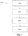
- the method can include steps for producing a second bearing surface, an intermediate surface, a centering surface and/or shaft mounts.
- FIG. 1 shows a schematic representation of a roller feed 1, as is known from the prior art.
- the roller feed 1 comprises two rollers 100, 150.
- a first roller 150 is arranged above and a second roller 100 is arranged below a workpiece to be conveyed.
- the second roller 100 is driven via an electric motor 70 and is coupled to the first roller 150 via an output shaft and a gear arrangement (here a spur gear) 20 .
- the first roller 150 can be adjusted in the radial direction by means of a Schmidt coupling 90 in order to be able to set a gap between the first and the second roller.
- the conventional rollers 100, 150 comprise a roller body 110 on which bearing shafts 180a, 180b are fixed in a rotationally fixed manner on both sides.
- the bearing shafts 180a, 180b are used to mount the roller 100, 150, to deliver an output torque and/or to absorb a drive torque.
- the roller 100 is connected to the rotor 72 of the electric motor 70 via the bearing shaft 180a and the drive shaft 73 .
- the drive torque is transmitted to the roller 150 via the gear arrangement 20 .
- the roller 100 and the corresponding drive/electric motor are assigned five bearings 200a, 200b, 220, 270a, 270b (roller bearings here).
- the roller 150 is associated with three bearings 222, 250a, 250b.
- the diameter of the bearing shafts in particular the diameter in the area where the drive torque is absorbed or the diameter in the area where the output torque is output, is small. In the event of overload or peak loads, this can lead to damage, in particular to the roller (or the bearing shafts) breaking. In addition, the connection between the roller body and the bearing shaft is often prone to damage, such as can be caused by overload. If a roller is damaged, it must be replaced. For this purpose, extensive dismantling of the roll feed 1 is necessary, since the rolls cannot simply be removed axially from the roll feed due to the bearing.
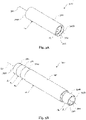
- roller feed 2 shows a schematic functional principle of a roller feed 2 according to the invention.
- the principle of the roller feed 2 is based on at least two rollers 300, 350. At least one of the rollers is designed as a tubular roller according to the invention.
- a first roller 300 is arranged on a first side of a workpiece 10 to be conveyed (here: above) and a second roller 350 is arranged on a second side of the workpiece 10 to be conveyed (here: below).
- the orientation of the roller feed is arbitrary, so that the workpiece can be conveyed horizontally, vertically or at any angle. If the roller feed comprises two rollers, these are typically arranged opposite one another. Other arrangements are also possible.
- a roller feed may comprise three rollers (or a different number of rollers), the rollers being arranged offset from one another, so that the workpiece is conveyed through the rollers in a type of wave motion.
- At least one of the rollers 300, 350 is a driven roller.
- the workpiece 10 is introduced into a gap formed between the rollers 300,350.
- the workpiece 10 is then advanced/conveyed in the X direction by rotating the rollers in the same direction in the direction of rotation ⁇ 300 , ⁇ 350 .
- the speed of rotation of the rollers determines the conveying or feed speed.
- roller 300 can interact with a roller clutch, such as a Schmidt clutch, which enables the roller to be adjusted in the radial direction Z.
- a roller clutch such as a Schmidt clutch
- the gap between two rollers can be adjusted to a material thickness of the workpiece 10 being conveyed/advanced.
- a simplified insertion of the workpiece between the rollers is made possible.
- Figure 3A shows a schematic representation of a tube roller 300 according to the invention.
- the tube roller 300 comprises a first end 305a and a second end 305b.
- a radially circumferential rolling surface 302 is disposed between the first end 305a and the second end 305b and is adapted to contact a workpiece.
- the rolling surface 302 has an outside diameter d a . This can be in the range from 30 mm to 200 mm, preferably in the range from 44 mm to 150 mm, more preferably in the range from 60 mm to 120 mm and most preferably in the range from 80 mm to 100 mm.
- the tube roller 300 has a hollow inner area 304 which has an inner diameter di.
- the rolling surface 302 and the hollow interior 304 are arranged substantially concentrically.
- the tube roller has a first bearing surface (see Fig. Figure 4A , 309a), which is set up to interact with a bearing in order to mount the tube roller 300 so that it can rotate about an axis of rotation 301.
- the first bearing surface has a diameter d la that satisfies the following condition: d i ⁇ d la ⁇ d a .
- the diameter d la of the first bearing surface in Figure 3A tube roller 300 shown is an inside diameter.
- the first bearing surface is arranged in the area of the rolling surface 302, which extends over the entire length of the roll.
- the axial length of the rolling surface (or the feed passage width) can be in the range from 250 mm to 2000 mm, preferably in the range from 320 mm to 1600 mm, more preferably in the range from 480 mm to 1200 mm and most preferably in the range of 640 mm up to 820 mm.
- the tube roller 300 comprises a shaft receptacle 308 which is set up to receive a bearing shaft in a rotationally fixed manner.
- Figure 3B shows a schematic representation of a further tube roller 350 according to the invention.
- the tube roller 350 comprises a first end 355a and a second end 355b.
- a radially circumferential rolling surface 352 of tube roller 350 is disposed between first end 355a and second end 355b and is configured to contact a workpiece.
- the rolling surface 352 has an outside diameter d a . This can be in the range of 30 mm to 200 mm, preferably in the range of 44 mm to 150 mm, more preferably in the range of 60 mm to 120 mm and most preferably in the range of 80 mm to 100 mm.
- the tubular roller In the area of the rolling surface 352, the tubular roller has a hollow inner area 354 which has an inner diameter di.
- the rolling surface 352 and the hollow interior portion 354 are arranged substantially concentrically.
- a first bearing surface 359a is configured to cooperate with a bearing to support the tube roller 350 rotatably about an axis of rotation 351 .
- the first bearing surface 359a has a diameter d la that satisfies the following condition: d i ⁇ d la ⁇ d a .
- the tube roller 350 further includes a second bearing surface 359b for rotatably supporting the tube roller, which is opposite to the first bearing surface 359a in the axial direction.
- the second bearing surface 359b has a diameter d lb that satisfies the following condition: d i ⁇ d lb ⁇ d a .
- the first bearing surface 359a and the second bearing surface 359b are configured in the configuration shown such that d lb ⁇ d la applies.
- the diameter d la of the first bearing surface 359a and the diameter d lb of the second bearing surface 359b are each outside diameters.
- the first bearing surface 359a is arranged between the first end 355a of the tube roller and the rolling surface 352 and the second bearing surface 359b between the second end 355b of the tube roller and the rolling surface 352 .
- the tube roller 350 is therefore suitable for being pushed into a roller feed in the axial direction (see Fig. Figure 4B ).
- the tube roller 350 includes a centering surface 360 which is set up to receive a rotor 72 of an electric motor 70 in a rotationally fixed manner (see Fig. Figure 4A ).
- the centering surface has 360 an outer diameter d z that satisfies the following conditions: d i ⁇ d z ⁇ d a and d i ⁇ d z ⁇ d a .
- the tube roller 350 is therefore suitable for being pushed into a roller feed in the axial direction (see Fig. Figure 4B ).
- the large diameter d z also minimizes the risk of roll breakage, eg due to overload, compared to conventional rolls.
- a clamping element 60 is arranged between the centering surface 360 and the rotor 72 of the electric motor 70 (see Fig. Figure 4A ).
- the clamping element 60 is, for example, a centering clamping element, such as a cone clamping element, so that the rotor 72 is centered relative to the tube roller 350 when the rotor 72 is held for rotation.
- the Tube roller 350 also includes a centering surface 360, which is designed for this purpose with a cone clamping element 60 (see Fig. Figure 4A ) to work together.
- the centering surface 360 is formed at the first end 355a of the tube roller 350 .
- the tube roller 350 also includes a gear element receptacle 320 which makes it possible to connect a gear element 22 (for example a toothed wheel) to the tube roller 350 in a torque-proof manner.
- the gear element receptacle is preferably arranged at the second end 355b of the tube roller.
- An intermediate surface 370 can be arranged between the centering surface 360 and the first bearing surface 359a, which has a diameter d zw , the diameter fulfilling the condition d z ⁇ d zw ⁇ d la .
- Intermediate surface 370 facilitates the sliding of a bearing onto bearing surface 359a.
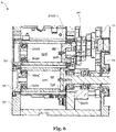
- Figure 4A shows a schematic representation of a roller feed according to the invention 4 and Figure 4B shows the roller feed 4 during assembly and disassembly.
- the roller feed 4 shown comprises a first roller 300, which is of the type shown in Figure 3A shown tube roller corresponds.
- the roller feed 4 includes a second roller 350, which is the one in Figure 3B shown tube roller corresponds.
- the first and the second roller 300, 350 are arranged in such a way that they are set up to convey a workpiece (not shown) through the roller feed 4.
- An electric motor 70 of the roller feed 4 is set up to drive the second roller 350 .
- the roller feed 4 also includes a gear arrangement 20.
- a first gear element 21 is assigned to the first roller 300 and a second gear element 22 to the second roller 350.
- a rotational movement of the second roller 350 is transmitted via the second gear element 22 to the first gear element 21 and then to the first roller 300 .
- the first and the second gear element are designed here as spur gears.
- a roller clutch 90 for example a Schmidt clutch, is arranged between the first transmission element 21 and the first roller 300 , which enables the first roller 300 to be adjusted in the radial direction Z relative to the second roller 350 .
- the first roller 300 remains coupled to the first transmission element via the roller clutch.
- the roller feed 4 shown also includes an actuator 95 which is set up to actively radially adjust the first roller 300 relative to the second roller 350 .
- the roller feed 4 further comprises a base body 30 which accommodates the first roller 300 and the second roller 350 .
- the base body 30 is designed in such a way that the rollers 300, 350 can be removed from the base body 30 in the axial direction, as shown in FIG Figure 4B shown. In the view of Figure 4B the first roller 300 can be removed from the base body to the right and the second roller 350 to the left.
- the body has a first bearing surface 39a associated with a first bearing surface 359a of tube roller 350 .
- the body has a second bearing surface 39b associated with a second bearing surface 359b of the tube roller 350 to rotatably support the tube roller 350 in the body 30 .
- Roller bearings 250a, 250b are arranged between the bearing surfaces 39a, 39b and 359a, 359b.
- the gear element 22 is connected to the roller 350 in a rotationally fixed manner at the second end 355b.
- the tube roller 350 receives a rotor 72 of the electric motor 70 on the centering surface 360 in a rotationally fixed manner.
- the tube roller can be centered via the centering surface 360, which is designed to interact with a clamping element 60. This arrangement makes it possible to reduce the number of bearings required to a minimum.
- the tube roller is mounted at only two points. Additional bearings for an input or output shaft can be omitted.
- the tube roller 300 has a first bearing surface 309a which cooperates with a bearing 200a to rotatably support the tube roller 300 about an axis of rotation.
- the tube roller 300 comprises a shaft receptacle 308 which receives a bearing shaft 80 in a rotationally fixed manner.
- the bearing shaft 80 is supported on the bearing 200b and is connected to the roller clutch 90 .
- the roller feed 4 also includes a rotary encoder 40 which is used to control the electric motor 70 .
- the encoder may be at least partially received within the hollow interior 354 of the tube roller 350 .
- FIG 5 shows a schematic representation of a further roller feed 5 according to the invention.
- the rotary encoder 40 is outside of the tubular roller 350 arranged.
- the rest of the structure of the roller feed 5 corresponds to the roller feed from the Figures 4A and 4B .
- a workpiece 10 is conveyed between the rollers 300 , 350 .
- roller feed 6 shows a schematic representation of a further roller feed 6 according to the invention.
- both rollers 300', 350' are similar to those in FIG Figure 3A shown tube roller 300 is formed.
- An electric motor (not shown) drives the lower roller 350' via a drive shaft which is also a bearing shaft 85'.
- the tube rollers 300', 350' each have a first bearing surface on 309a, 359a, which cooperate with a bearing 200a, 250a to support the tube roller 300', 350' rotatably about an axis of rotation.
- the tube roller 300' comprises a shaft receptacle 308 which receives a bearing shaft 80' in a rotationally fixed manner.
- the bearing shaft 80 is mounted on the bearing 200b and is connected to the transmission element 21 via the roller clutch 90 .
- the tube roller 350' comprises a shaft receptacle 358 which receives a bearing shaft 85' in a rotationally fixed manner.
- the bearing shaft 85' is mounted on the bearing 250b and is connected to an electric motor for driving the roller 350'.
- a gear element 22 is held in a rotationally fixed manner on the bearing shaft 85' and engages with the gear element 21 in order to also drive the roller 300'.
- the bearings 200a, 250a' are each accommodated on bearing surfaces of the base body 30 of the roll feeder 6.
- the base body 30 is designed in several pieces and includes a housing.
- the base body 30 of the roller feed 6 is designed in such a way that the tube rollers 300′, 350′ can be removed from the base body 30 in the axial direction (to the left in the illustration shown).
- the base body has at least one installation opening.
- the base body 30 has two installation openings.
- the roller 300' can be inserted or removed axially through a first installation opening.
- the roller 350' can be inserted or removed axially through a second installation opening.
- the installation openings are each closed with a cap, in particular a centered cap 34 , 35 , the centered cap encompassing a bearing surface of the base body 30 . This means that the tube rollers can be installed/exchanged easily.
Abstract
Die vorliegende Erfindung betrifft eine Rohrwalze, einen Walzenvorschub und ein Verfahren zur Herstellung einer Rohrwalze, wobei die Rohrwalze 300; 350 ein erstes Ende 305a; 355a und ein zweites Ende 305b; 355b sowie eine radial umlaufende Walzfläche 302; 352 umfasst. Die Walzfläche ist zwischen dem ersten und dem zweiten Ende angeordnet und dazu eingerichtet mit einem Werkstück 10 in Kontakt zu kommen. Die Walzfläche 302; 352 weist einen Außendurchmesser d<sub>a</sub> auf. Im Bereich der Walzfläche weist die Rohrwalze einen hohlen Innenbereich 304; 354 auf, der einen Innendurchmesser di aufweist, wobei die Walzfläche 302; 352 und der hohle Innenbereich 304; 354 im Wesentlichen konzentrisch angeordnet sind. Die Rohrwalze umfasst zudem eine erste Lagerfläche 309a; 359a, die dazu eingerichtet ist mit einem Lager zusammenzuwirken, um die Rohrwalze 300; 350 um eine Rotationsachse 301; 351 drehbar zu lagern, wobei die erste Lagerfläche 309a; 359a einen Durchmesser d<sub>la</sub> aufweist, der die folgende Bedingung erfüllt: d<sub>i</sub> ≤ d<sub>la</sub> ≤ d<sub>a</sub>.The present invention relates to a tube roll, a roll feed and a method of manufacturing a tube roll, wherein the tube roll 300; 350 a first end 305a; 355a and a second end 305b; 355b and a radially circumferential rolling surface 302; 352 included. The rolling surface is disposed between the first and second ends and is adapted to contact a workpiece 10 . The rolling surface 302; 352 has an outer diameter d<sub>a</sub>. In the area of the rolling surface, the tubular roller has a hollow inner area 304; 354, which has an inner diameter di, the rolling surface 302; 352 and the hollow interior 304; 354 are arranged substantially concentrically. The tube roller also includes a first bearing surface 309a; 359a, adapted to cooperate with a bearing to hold the tube roller 300; 350 about a rotation axis 301; 351 rotatably, the first bearing surface 309a; 359a has a diameter d<sub>la</sub> that satisfies the following condition: d<sub>i</sub> ≤ d<sub>la</sub> ≤ d<sub>a</sub>.
Description
Die vorliegende Erfindung betrifft eine Rohrwalze insbesondere für einen Walzenvorschub, einen Walzenvorschub umfassend zumindest eine Rohrwalze und ein Verfahren zur Herstellung einer Rohrwalze.The present invention relates to a tube roll, in particular for a roll feed, a roll feed comprising at least one tube roll and a method for producing a tube roll.
Walzenvorschübe werden beispielsweise zum Fördern und Vorschieben, insbesondere zum getakteten Vorschieben von Werkstücken, wie Band- oder Streifenmaterial, eingesetzt. Beispielhaft kommen Walzenvorschübe bei Stanzanwendung zum Einsatz. Das Werkstück wird hierbei getaktet vorgeschoben, wobei die Taktung des Vorschubs mit einem Stanzwerkzeug synchronisiert ist.Roller feeds are used, for example, for conveying and feeding, in particular for the clocked feeding of workpieces such as band or strip material. For example, roller feeds are used in punching applications. In this case, the workpiece is fed in a clocked manner, with the clocking of the feed being synchronized with a punching tool.
Ebenso sind Walzenvorschübe aus anderen Anwendungsgebieten bekannt. Beispielsweise kann ein Walzenvorschub eine profilierte Walze aufweisen und beim Vorschieben des Werkstücks die entsprechende Profilierung in das Werkstück einprägen oder einstanzen.Roller feeds are also known from other areas of application. For example, a roller feed can have a profiled roller and emboss or stamp the corresponding profile into the workpiece as the workpiece is advanced.
Das Prinzip des Walzenvorschubes basiert grundsätzlich auf zumindest zwei Walzen, wovon mindestens eine erste Walze auf einer ersten Seite (beispielsweise oberhalb) des zu fördernden Werkstücks und eine zweite Walze auf einer gegenüberliegenden Seite (beispielsweise unterhalb) des zu fördernden Werkstücks angeordnet sind, wie in
Zumindest eine der Walzen ist eine angetriebene Walze. Zum Vorschieben/Fördern wird das Werkstück in einen Spalt, der zwischen den Walzen ausgebildet ist, eingeführt. Durch eine gleichlaufende Drehung der Walzen wird das Werkstück sodann vorgeschoben / gefördert. Die Drehgeschwindigkeit der Walzen bestimmt die Förder- bzw. Vorschubgeschwindigkeit.At least one of the rollers is a driven roller. For feeding/conveying, the workpiece is pushed into a gap formed between the rollers introduced. The workpiece is then advanced/conveyed by a parallel rotation of the rollers. The speed of rotation of the rollers determines the conveying or feed speed.
Herkömmliche Walzen, umfassen typischerweise einen Walzenkörper, an dem beidseitig Lagerwellen drehfest angebracht sind. Die Lagerwellen dienen der Lagerung der Walze, der Abgabe eines Abtriebsmoments und/oder der Aufnahme eines Antriebsmoments. Typischerweise ist jede Walze separat gelagert. Eine Antriebswelle eines Motors oder eines Getriebes, die ein Antriebsmoment auf die Walze überträgt, bzw. eine Abtriebswelle, die ein Abtriebsmoment der Walze aufnimmt muss zusätzlich gelagert werden. Für eine Walzenanordnung müssen somit typischerweise jedenfalls vier Lagerstellen bereitgestellt werden.Conventional rollers typically include a roller body on which bearing shafts are attached in a rotationally fixed manner on both sides. The bearing shafts are used to mount the roller, to deliver an output torque and/or to absorb a drive torque. Typically, each roll is stored separately. A drive shaft of a motor or a transmission, which transmits a drive torque to the roller, or an output shaft, which absorbs an output torque from the roller, must be additionally mounted. In any case, four bearing points must therefore typically be provided for a roller arrangement.
Zudem ist die Fertigung herkömmlicher Walzen aufwendig und teuer, da die Lagerwellen mit dem Walzenkörper so verbunden werden müssen, dass die beiden Lagerwellen und der Walzenkörper exakt koaxial ausgerichtet sind. Typischerweise weist der Walzenkörper entsprechende Lagerwellenaufnahmen auf, die jeweils mit einer entsprechenden Lagerwelle formschlüssig, formschlüssig und stoffschlüssig und/oder formschlüssig und kraftschlüssig zusammengreifen. Um eine exakte Ausrichtung der beiden Lagerwellen und des Wellenkörpers zu erreichen, müssen die Lagerwellenaufnahmen und entsprechende Aufnahmeflansche der Lagerwellen mit hoher Präzision und geringen Toleranzen gefertigt werden. Dies macht die Herstellung teuer und aufwendig. In der Regel sind viele Verfahrensschritte zur Herstellung einer konventionellen Walze notwendig. Somit sind die Lieferzeiten für konventionelle Walzen lang und die Zahl der Anbieter ist gering.In addition, the production of conventional rollers is complex and expensive, since the bearing shafts must be connected to the roller body in such a way that the two bearing shafts and the roller body are aligned exactly coaxially. The roller body typically has corresponding bearing shaft receptacles, which each engage with a corresponding bearing shaft in a form-fitting, form-fitting and material-fitting manner and/or in a form-fitting and force-fitting manner. In order to achieve an exact alignment of the two bearing shafts and the shaft body, the bearing shaft mounts and corresponding mounting flanges of the bearing shafts must be manufactured with high precision and low tolerances. This makes production expensive and complex. As a rule, many process steps are necessary to produce a conventional roller. As a result, the delivery times for conventional rollers are long and the number of suppliers is small.
Weiterhin ist bei den konventionellen Walzen der Durchmesser der Lagerwellen, insbesondere der Durchmesser im Bereich der Antriebsmoment-Aufnahme bzw. der Durchmesser im Bereich einer Abtriebsmoment-Abgabe gering. Bei Überlast oder Lastspitzen kann dies zu Beschädigungen, insbesondere zum Bruch der Walze (bzw. der Lagerwellen) führen. Zudem ist die Verbindung von Walzenkörper und Lagerwelle oftmals anfällig für Beschädigungen, wie sie durch Überlast hervorgerufen werden können.Furthermore, in the case of conventional rollers, the diameter of the bearing shafts, in particular the diameter in the area where the drive torque is absorbed or the diameter in the area where the output torque is output, is small. In the event of overload or peak loads, this can lead to damage, in particular to the roller (or the bearing shafts) breaking. In addition, the connection between the roller body and the bearing shaft is often prone to damage, such as can be caused by overload.
Wird eine Walze beschädigt, muss diese getauscht werden. Oftmals ist hierzu eine weitreichende Demontage des Walzenvorschubs notwendig. Hiermit sind unerwünscht lange Standzeiten des Walzenvorschubs verbunden.If a roller is damaged, it must be replaced. Extensive dismantling of the roller feed is often necessary for this. This is associated with undesirably long downtimes of the roller feed.
Aufgabe der vorliegenden Erfindung ist es die vorgenannten Nachteile jedenfalls teilweise auszuräumen. Insbesondere soll eine Walze und ein Walzenvorschub bereitgestellt werden, die die Nachteile jedenfalls teilweise überkommen.The object of the present invention is to eliminate at least some of the aforementioned disadvantages. In particular, a roller and a roller feed are to be provided which at least partially overcome the disadvantages.
Die Walze soll einen vereinfachten Aufbau aufweisen und einfach und kostengünstig herzustellen sein. Zudem soll ein Walzenvorschub, bereitgestellt werden, der einen vereinfachten Einbau bzw. einen leichten Austausch der Walze(n) ermöglicht.The roller should have a simplified structure and be easy and inexpensive to manufacture. In addition, a roller feed is to be provided, which enables simplified installation or easy replacement of the roller(s).
Diese Aufgaben werden, jedenfalls teilweise, durch eine erfindungsgemäße Rohrwalze, einen Walzenvorschub und ein Verfahren zur Herstellung einer Rohrwalze gemäß den unabhängigen Ansprüchen gelöst. Weitere Aspekte der Erfindung sind in den abhängigen Ansprüchen aufgeführt.These objects are achieved, at least in part, by a tube roll according to the invention, a roll feed and a method for producing a tube roll according to the independent claims. Further aspects of the invention are set out in the dependent claims.
Insbesondere werden die obigen Aufgaben, jedenfalls teilweise, durch eine erfindungsgemäße Rohrwalze gelöst. Die Rohrwalze umfasst ein erstes Ende und ein zweites Ende sowie eine radial umlaufende Walzfläche auf, welche zwischen dem ersten und dem zweiten Ende angeordnet ist und dazu eingerichtet ist mit einem Werkstück in Kontakt zu kommen. Die Walzfläche kann insbesondere eine zylindrische Walzfläche sein.In particular, the above objects are achieved, at least in part, by a tube roller according to the invention. The tube roller includes a first end and a second end, and a radially circumferential roller surface disposed between the first and second ends and configured to contact a workpiece. The rolling surface can in particular be a cylindrical rolling surface.
Die Rohrwalze ist insbesondere für einen Walzenvorschub eingerichtet. Das Werkstück, dass mit der Walzfläche in Kontakt kommt kann ein Band- oder Streifenmaterial sein, welches - sofern die Rohrwalze in einen Walzenvorschub eingebaut ist - mittels der Rohrwalze gefördert/vorgeschoben wird. Die Übertragung der Förder- bzw. Vorschubbewegung von der Walze auf das Werkstück erfolgt über die Walzfläche.The tube roller is set up in particular for a roller feed. The workpiece that comes into contact with the rolling surface can be a band or strip material which—if the tube roller is built into a roller feed—is conveyed/advanced by means of the tube roller. The conveying or feed movement is transmitted from the roller to the workpiece via the roller surface.
Die Walzfläche weist einen Außendurchmesser da auf (konvexer Bereich). Die Walzfläche mit Außendurchmesser da kann profiliert sein. Insbesondere kann die Walzfläche Vorsprünge und/oder Rücksprünge aufweisen, die ein gefördertes Werkstück beim Fördern profilieren und/oder stanzen. Wird die Rohrwalze zum Profilieren/Stanzen in einem Walzenvorschub verwendet, wirkt sie typischerweise mit einer zweiten Walze zusammen. Die Walzfläche der Rohrwalze kann eine Positiv-Form oder eine Negativ-Form aufweisen. Eine Walzfläche der zweiten Walze, welche ebenfalls eine Rohrwalze sein kann, weist entsprechend eine Negativ-Form oder ein Positiv-Form auf.The rolling surface has an outer diameter d a (convex area). The rolling surface with outside diameter d a can be profiled. In particular, the rolling surface can have projections and/or recesses which profile and/or punch a conveyed workpiece during conveying. When the tube roll is used for profiling/stamping in a roll feed, it typically interacts with a second roll. The rolling surface of the tube roller can have a positive shape or a negative shape. A rolling surface of the second roller, which can also be a tubular roller, accordingly has a negative shape or a positive shape.
Der Außendurchmesser da der Walzfläche kann im Bereich von 30 mm bis 200 mm liegen, bevorzugt im Bereich von 44 mm bis 150 mm, weiter bevorzugt im Bereich von 60 mm bis 120 mm und am meisten bevorzugt im Bereich von 80 mm bis 100 mm. Die axiale Länge Walzfläche (bzw. der Vorschubdurchlassbreite) kann im Bereich von 250 mm bis 2000 mm liegen, bevorzugt im Bereich von 320 mm bis 1600 mm, weiter bevorzugt im Bereich von 480 mm bis 1200 mm und am meisten bevorzugt im Bereich von 640 mm bis 820 mm.The outer diameter d a of the rolling surface can be in the range from 30 mm to 200 mm, preferably in the range from 44 mm to 150 mm, more preferably in the range from 60 mm to 120 mm and most preferably in the range from 80 mm to 100 mm. The axial length of the rolling surface (or the feed passage width) can be in the range from 250 mm to 2000 mm, preferably in the range from 320 mm to 1600 mm, more preferably in the range from 480 mm to 1200 mm and most preferably in the range of 640 mm up to 820 mm.
Zudem weist die Rohrwalze im Bereich der Walzfläche einen hohlen Innenbereich auf, der einen Innendurchmesser di aufweist (konkaver Bereich). Die Walzfläche und der hohle Innenbereich sind im Wesentlichen konzentrisch angeordnet sind (Fertigungstoleranzen eingeschlossen). Insbesondere kann die Rohrwalze aus einem Rohr hergestellt worden sein, welches einen hohlen Innenbereich mit einem Innendurchmesser aufweist. Der Innendurchmesser di des hohlen Innenbereichs der Rohrwalze kann dem Innendurchmesser des hohlen Innenbereichs des Rohres entsprechen, oder der Innenbereich der Rohrwalze kann nachbearbeitet sein (z.B. durch Spanen, Schleifen, oder andere Fertigungsverfahren), sodass der Innendurchmesser di des hohlen Innenbereichs der Rohrwalze größer ist als der Innendurchmesser des Innenbereichs des Rohres.In addition, the tubular roller has a hollow inner area in the area of the rolling surface, which has an inner diameter d i (concave area). The rolling surface and hollow interior are substantially concentric (manufacturing tolerances included). In particular, the tube roller may have been made from a tube having a hollow interior with an inner diameter. The inner diameter d i of the hollow interior of the tube roll can correspond to the inner diameter of the hollow interior of the tube, or the interior of the tube roll can be finished (e.g. by machining, grinding, or other manufacturing processes) so that the inner diameter d i of the hollow interior of the tube roll is larger is the inner diameter of the interior of the tube.
Vorzugsweise weist die Rohrwalze im Bereich der Walzfläche eine Wandstärke t (t=(da-di)/2) im Bereich von 3 mm bis 15 mm, vorzugsweise im Bereich von 4 mm bis 10 mm und insbesondere bevorzugt im Bereich von 5 mm bis 7 mm auf.In the region of the rolling surface, the tubular roller preferably has a wall thickness t (t=(d a -d i )/2) in the range from 3 mm to 15 mm, preferably in the range from 4 mm to 10 mm and particularly preferably in the range of 5 mm up to 7 mm.
Das Rohr aus dem die Rohrwalze hergestellt worden sein kann, kann ein geschweißtes oder ein nahtloses Rohr sein. Beispielsweise kann das Rohr durch eines der folgenden Verfahren hergestellt worden sein: Strangpressen, Stranggießen, Schleudergießen, Schrägwalzen, Stopfenwalzen, Streckreduzieren, ein Stoßbankverfahren, ein Pilgerschrittverfahren und/oder dergleichen. Ebenso ist es möglich, dass das Rohr ein spanend hergestelltes Rohr ist.The tube from which the tube roller may be made may be welded or seamless tube. For example, the tube may have been made by any of the following processes: extrusion, continuous casting, centrifugal casting, cross rolling, plug rolling, stretch reducing, a push bench process, a pilger step process, and/or the like. It is also possible for the tube to be a machined tube.
Die Rohrwalze umfasst zudem eine erste Lagerfläche, die dazu eingerichtet ist mit einem Lager zusammenzuwirken, um die Rohrwalze um eine Rotationsachse drehbar zu lagern. Die erste Lagerfläche weist einen Durchmesser dla auf, der die folgende Bedingung erfüllt: di ≤ dla ≤ da.The tube roller also includes a first bearing surface which is designed to interact with a bearing in order to support the tube roller so that it can rotate about an axis of rotation. The first bearing surface has a diameter d la that satisfies the following condition: d i ≦d la ≦d a .
Die erste Lagerfläche kann insbesondere dazu eingerichtet sein mit einem Rotationslager, wie beispielsweise einem Gleitlager, einem Wälzlager, oder dergleichen zusammenzuwirken. Wirkt die Lagerfläche beispielsweise mit einem Gleitlager zusammen, kann die Lagerfläche eine entsprechende Oberflächengüte aufweisen, um sich in einer Gleitlagerbuchse des Gleitlagers radial zu drehen. Soll die Lagerfläche mit einem Wälzlager zusammenwirken, kann die Lagerfläche einen Lagerring des Wälzlagers aufnehmen (z.B. formschlüssig und/oder kraftschlüssig).The first bearing surface can in particular be set up with a rotary bearing, such as a plain bearing, a roller bearing, or the like to cooperate. If the bearing surface interacts with a plain bearing, for example, the bearing surface can have a corresponding surface quality in order to rotate radially in a plain bearing bush of the plain bearing. If the bearing surface is to interact with a roller bearing, the bearing surface can accommodate a bearing ring of the roller bearing (eg with a positive fit and/or with a force fit).
Mithin ist der Durchmesser der ersten Lagerfläche größer oder gleich dem Innendurchmesser di des hohlen Innenbereichs der Rohrwalze und kleiner oder gleich dem Durchmesser da der Walzfläche. Die erste Lagerfläche kann somit integral mit der Rohrwalze ausgebildet sein. Beispielsweise kann die Lagerfläche an die Rohrwalze angedreht worden sein, da der Durchmesser dla der ersten Lagerfläche (in radialer Richtung gesehen) im Bereich der Wandstärke des Bereichs liegt, indem die Walzfläche angeordnet ist. Die Lagerfläche kann auch durch andere Herstellungsverfahren (z.B. spanend oder schleifend) hergestellt worden sein.Thus, the diameter of the first bearing surface is greater than or equal to the inside diameter d i of the hollow interior of the tube roller and smaller than or equal to the diameter d a of the rolling surface. The first bearing surface can thus be formed integrally with the tube roller. For example, the bearing surface may have been turned onto the tube roller, since the diameter d la of the first bearing surface (seen in the radial direction) is in the range of the wall thickness of the area in which the roller surface is arranged. The bearing surface can also have been produced by other production processes (eg by cutting or grinding).
Die erste Lagerfläche weist einen im verglich zu herkömmlichen Walzen sehr großen Durchmesser auf, sodass die Gefahr einer Beschädigung und/oder eines Überlastbruchs der Rohrwalze minimiert ist. Zudem ist die erste Lagerfläche nicht auf einer separaten Lagerwelle angeordnet, sodass die Gefahr einer Beschädigung, z.B. durch Überlast, weiter reduziert werden kann.The first bearing surface has a very large diameter compared to conventional rolls, so that the risk of damage and/or overload fracture of the tube roll is minimized. In addition, the first bearing surface is not arranged on a separate bearing shaft, so that the risk of damage, e.g. due to overload, can be further reduced.
Die Rohrwalze kann weiterhin eine zweite Lagerfläche, zur drehbaren Lagerung der Rohrwalze umfassen, die der ersten Lagerfläche in axialer Richtung gegenüberliegt. Insbesondere kann die erste Lagerfläche in der Nähe des ersten Endes oder am ersten Ende und die zweite Lagerfläche in der Nähe des zweiten Endes oder am zweiten Ende angeordnet sein. Die zweite Lagerfläche kann insbesondere dazu eingerichtet sein mit einem Rotationslager, wie beispielsweise einem Gleitlager, einem Wälzlager, oder dergleichen zusammenzuwirken. Wirkt die Lagerfläche beispielsweise mit einem Gleitlager zusammen, kann die Lagerfläche eine entsprechende Oberflächengüte aufweisen, um sich in einer Gleitlagerbuchse des Gleitlagers radial zu drehen. Soll die Lagerfläche mit einem Wälzlager zusammenwirken, kann die Lagerfläche einen Lagerring des Wälzlagers aufnehmen (z.B. formschlüssig und/oder kraftschlüssig).The tube roller can further comprise a second bearing surface, for rotatably supporting the tube roller, which is opposite the first bearing surface in the axial direction. In particular, the first bearing surface can be arranged in the vicinity of the first end or at the first end and the second bearing surface can be arranged in the vicinity of the second end or at the second end. The second bearing surface can in particular be set up to interact with a rotary bearing, such as a plain bearing, a roller bearing or the like. If the bearing surface interacts with a plain bearing, for example, the bearing surface can have a corresponding surface quality in order to rotate radially in a plain bearing bush of the plain bearing. If the bearing surface is to interact with a roller bearing, the bearing surface can accommodate a bearing ring of the roller bearing (e.g. in a positive and/or non-positive manner).
Die zweite Lagerfläche weist einen Durchmesser dlb auf, der die folgende Bedingung erfüllt: di ≤ dlb ≤ da.The second bearing surface has a diameter d lb that satisfies the following condition: d i ≦d lb ≦d a .
Mithin ist der Durchmesser der zweiten Lagerfläche größer oder gleich dem Innendurchmesser di des hohlen Innenbereichs der Rohrwalze und ldeiner oder gleich dem Durchmesser da der Walzfläche. Die zweite Lagerfläche kann somit integral mit der Rohrwalze ausgebildet sein. Beispielsweise kann die Lagerfläche an die Rohrwalze angedreht worden sein, da der Durchmesser dlb der zweiten Lagerfläche (in radialer Richtung gesehen) im Bereich der Wandstärke des Bereichs liegt, indem die Walzfläche angeordnet ist. Die Lagerfläche kann auch durch andere Herstellungsverfahren (z.B. spanend oder schleifend) hergestellt worden sein. Die zweite Lagerfläche weist einen im verglich zu herkömmlichen Walzen sehr großen Durchmesser auf, sodass die Gefahr einer Beschädigung und/oder eines Überlastbruchs der Rohrwalze minimiert ist.Thus, the diameter of the second bearing surface is greater than or equal to and smaller than or equal to the inside diameter d i of the hollow interior of the tube roller the diameter d a of the rolling surface. The second bearing surface can thus be formed integrally with the tube roller. For example, the bearing surface may have been turned onto the tube roller, since the diameter d lb of the second bearing surface (seen in the radial direction) is in the range of the wall thickness of the area in which the roller surface is arranged. The bearing surface can also have been produced by other production processes (eg by cutting or grinding). The second bearing surface has a very large diameter compared to conventional rollers, so that the risk of damage and/or overload fracture of the tube roller is minimized.
Zudem sind die erste Lagerfläche und die zweite Lagerfläche optional so ausgestaltet sind, dass dlb < dla gilt. Dies ermöglicht den vereinfachten Einbau der Rohrwalze in einen Walzenvorschub. Beispielsweise kann die Rohrwalze mit dem kleinen Lagerdurchmesser dlb der zweiten Lagerfläche voran in den Walzenvorschub in axialer Richtung eingeschoben bzw. entnommen werden. Hierzu muss in dem Walzenvorschub lediglich eine Installationsöffnung für die Rohrwalze vorgesehen sein, die so dimensioniert ist, dass die Rohrwalze durch die Installationsöffnung hindurchpasst. Weist die Rohrwalze nur eine Lagerfläche (d.h. die erste Lagerfläche auf), wird die Rohrwalze vorzugsweise mit der ersten Lagerfläche voran in einen Walzeneinschub eingeschoben. Ebenso ist es möglich die Rohrwalze entgegengesetzt einzuschieben.In addition, the first bearing surface and the second bearing surface are optionally configured such that d lb <d la applies. This enables the tube roller to be easily installed in a roller feed. For example, the tube roller with the small bearing diameter d lb of the second bearing surface in front can be pushed into or removed from the roller feed in the axial direction. For this purpose, only an installation opening for the tube roller must be provided in the roller feed, which is dimensioned such that the tube roller fits through the installation opening. If the tube roller has only one bearing surface (ie the first bearing surface), the tube roller is preferably inserted into a roller slot with the first bearing surface first. It is also possible to insert the tube roller in the opposite direction.
Der Durchmesser dla der ersten Lagerfläche und/oder der Durchmesser dlb der zweiten Lagerfläche kann ein Innendurchmesser sein. Optional kann die erste Lagerfläche und/oder die zweite Lagerfläche im Bereich der Walzfläche angeordnet sein. Die Lagerfläche(n) und die Walzfläche können somit in einem integralen Bauteil ausgebildet sein. Da in diesem Fall die ersten Lagerfläche und/oder die zweite Lagerfläche eine innenliegende Fläche ist, kann nahezu die gesamte Länge der Rohrwalze (vom ersten Ende bis zum zweiten Ende) als Walzfläche genutzt werden. Dies ermöglicht die Bereitstellung sehr kurzer Rohrwalzen, da in axialer Richtung kein zusätzlicher Bauraum für die Lagerflächen vorgesehen werden muss.The diameter d la of the first bearing surface and/or the diameter d lb of the second bearing surface can be an inside diameter. Optionally, the first bearing surface and/or the second bearing surface can be arranged in the area of the rolling surface. The bearing surface(s) and the rolling surface can thus be formed in an integral component. Since in this case the first bearing surface and/or the second bearing surface is an inner surface, almost the entire length of the tube roller (from the first end to the second end) can be used as a rolling surface. This makes it possible to provide very short tube rollers, since no additional installation space has to be provided for the bearing surfaces in the axial direction.
Ebenso kann der Durchmesser dla der ersten Lagerfläche und/oder der Durchmesser dlb der zweiten Lagerfläche ein Außendurchmesser sein. Ebenso ist es möglich, dass der Durchmesser dla ein Außendurchmesser und der Durchmesser dlb ein Innendurchmesser ist. Auch ist es möglich, dass der Durchmesser dlb ein Außendurchmesser und der Durchmesser dla ein Innendurchmesser ist.Likewise, the diameter d la of the first bearing surface and/or the diameter d lb of the second bearing surface can be an outside diameter. It is also possible that the diameter d la is an outside diameter and the diameter d lb is an inside diameter. It is also possible that the diameter d lb is an outside diameter and the diameter d la is an inside diameter.
Optional ist die erste Lagerfläche zwischen dem ersten Ende der Rohrwalze und der Wälzfläche und/oder die zweite Lagerfläche zwischen dem zweiten Ende der Rohrwalze und der Wälzfläche angeordnet. Die Lagerfläche(n) und die Walzfläche können somit in einem integralen Bauteil ausgebildet sein. Da in diesem Fall die ersten Lagerfläche und/oder die zweite Lagerfläche eine außenliegende Fläche ist, ist/sind die Lagerflächen gut zugänglich und kann/können einfach gefertigt werden (z.B. durch Drehen oder Schleifen). Dies ermöglicht eine kostengünstige Fertigung.Optionally, the first bearing surface is arranged between the first end of the tubular roller and the rolling surface and/or the second bearing surface is arranged between the second end of the tubular roller and the rolling surface. The bearing surface(s) and the rolling surface can thus be formed in an integral component. Since in this case the first bearing surface and/or the second bearing surface is an external surface, the bearing surface is/are easily accessible and can be easily manufactured (e.g. by turning or grinding). This enables cost-effective production.
Die Rohrwalze kann an dem zweiten Ende eine Wellenaufnahme umfassen, welche dazu eingerichtet ist, eine Lagerwelle drehfest aufzunehmen. Insbesondere kann in der Wellenaufnahm eine Lagerwelle drehfest aufgenommen sein. Die drehfeste Aufnahme kann form-, kraft- und/oder stoffschlüssig erfolgen, beispielweise durch Verschrauben, Verpressen, Verschweißen, und/oder andere Wellenverbindungstechniken. Die Lagerwelle kann beispielsweise mit einer Walzenkupplung, wie einer Schmidt-Kupplung, zusammenwirken, die es ermöglicht die Rohrwalze in radialer Richtung zu verstellen und die die Walze zugleich mit einer in radialer Richtung unbeweglichen Welle koppelt. Somit kann in einem Walzenvorschub der Spalt zwischen zwei Walzen auf eine Materialstärke des geförderten/vorgeschobenen Werkstücks eingestellt werden.At the second end, the tubular roller can comprise a shaft receptacle which is set up to receive a bearing shaft in a rotationally fixed manner. In particular, a bearing shaft can be accommodated in a rotationally fixed manner in the shaft receptacle. The non-rotatable mount can be positive, non-positive and/or material, for example by screwing, pressing, welding and/or other shaft connection techniques. The bearing shaft can, for example, interact with a roller coupling, such as a Schmidt coupling, which makes it possible to adjust the tube roller in the radial direction and at the same time couples the roller to a shaft that is immovable in the radial direction. Thus, in a roller feed, the gap between two rollers can be adjusted to a material thickness of the workpiece being conveyed/advanced.
Die Rohrwalze kann eine Zentrierfläche umfassen, welche dazu eingerichtet ist, einen Rotor eines Elektromotors drehfest aufzunehmen. Die Zentrierfläche weist dann einen Innendurchmesser oder einen Außendurchmesser auf, wobei der Durchmesser der Zentrierfläche dz die folgende Bedingung erfüllt: di ≤ dz < da und optional auch die folgende Bedingung erfüllt: di ≤ dz < dla The tubular roller can include a centering surface which is set up to receive a rotor of an electric motor in a rotationally fixed manner. The centering surface then has an inside diameter or an outside diameter, with the diameter of the centering surface d z satisfying the following condition: d i ≦d z <d a and optionally also the following condition: d i ≦d z <d a
Die Zentrierfläche ist eine radial umlaufende Fläche. Weist die Zentrierfläche einen Innendurchmesser auf (d.h. sie ist konkav), kann der Rotor ein Rotor eines Elektromotors mit Außenläufer sein. Weist die Zentrierfläche einen Außendurchmesser auf (d.h. sie ist konvex), kann der Rotor ein Rotor eines Elektromotors mit Innenläufer sein. Durch die Aufnahme des Rotors auf einer Zentrierfläche der Rohrwalze kann die Anzahl der Lager in einem entsprechenden Walzenvorschub minimiert werden, da die Rohrwalze zugleich die Antriebswelle ist. Eine separate Lagerung einer Antriebswelle entfällt.The centering surface is a radially circumferential surface. If the centering surface has an inner diameter (i.e., it is concave), the rotor may be a rotor of an external rotor electric motor. If the centering surface has an outer diameter (i.e. it is convex), the rotor may be a rotor of an internal rotor electric motor. By accommodating the rotor on a centering surface of the tube roll, the number of bearings in a corresponding roll feed can be minimized, since the tube roll is also the drive shaft. A separate storage of a drive shaft is not required.
Erfüllt der Durchmesser dz der Zentrierfläche die Bedingung di ≤ dz < da ist der Durchmesser der Zentrierfläche größer oder gleich dem Innendurchmesser di des hohlen Innenbereichs der Rohrwalze und kleiner als der Durchmesser da der Walzfläche. Die Zentrierfläche kann somit integral mit der Rohrwalze ausgebildet sein. Beispielsweise kann die Zentrierfläche an die Rohrwalze angedreht worden sein, da der Durchmesser dz der Zentrierfläche (in radialer Richtung gesehen) im Bereich der Wandstärke des Bereichs liegt, indem die Walzfläche angeordnet ist. Die Zentrierfläche kann auch durch andere Herstellungsverfahren (z.B. spanend oder schleifend) hergestellt worden sein. Zudem weist die Zentrierfläche einen im vergleich zu herkömmlichen Walzen bzw. Antriebswellen sehr großen Durchmesser auf, sodass die Gefahr einer Beschädigung und/oder eines Überlastbruchs der Rohrwalze minimiert ist.If the diameter d z of the centering surface satisfies the condition d i ≦d z <d a , the diameter of the centering surface is greater than or equal to the inside diameter d i of the hollow interior of the tube roller and smaller than the diameter d a der rolling surface. The centering surface can thus be formed integrally with the tube roller. For example, the centering surface may have been turned onto the tube roller, since the diameter d z of the centering surface (seen in the radial direction) is in the range of the wall thickness of the area in which the roller surface is arranged. The centering surface can also have been produced by other production processes (eg by cutting or grinding). In addition, the centering surface has a very large diameter compared to conventional rollers or drive shafts, so that the risk of damage and/or overload fracture of the tube roller is minimized.
Ist die Bedingung di ≤ dz < dla erfüllt und weist die Zentrierfläche einen Außendurchmesser auf, kann die Rohrwalze einfach in einen Walzenvorschub eingebaut werden (z.B. durch axiales Einschieben), da der Durchmesser dz der Zentrierfläche kleiner ist als der Durchmesser dla der ersten Lagerfläche. Weist die Zentrierfläche einen Innendurchmesser auf, kann entsprechend die Bedingung di ≤ dla < dz erfüllt sein, um einen einfachen Einbau zu ermöglichen.If the condition d i ≤ d z < dl a is met and the centering surface has an outside diameter, the tube roller can be easily installed in a roll feed (e.g. by pushing it in axially), since the diameter d z of the centering surface is smaller than the diameter d la the first storage area. If the centering surface has an inner diameter, the condition d i ≦dl a <d z can accordingly be met in order to enable simple installation.
Zwischen der Zentrierfläche und dem Rotor des Elektromotors kann ein Spannelement angeordnet sein. Das Spannelement ist beispielsweise ein zentrierendes Spannelement, wie ein Konus-Spannelement, sodass der Rotor relativ zur Rohrwalze zentriert wird, wenn Rotor drehfest aufgenommen ist. Die Zentrierfläche ist optional am ersten Ende der Rohrwalze ausgebildet. Insbesondere kann die Zentrierfläche integral mit der Rohrwalze ausgebildet sein und beispielsweise am ersten Ende der Rohrwalze angedreht sein. Die Zentrierfläche ermöglicht die exakte Zentrierung der Rohrwalze. Somit kann ein optimaler Rundlauf der Rohrwalze erreicht werden.A clamping element can be arranged between the centering surface and the rotor of the electric motor. The clamping element is, for example, a centering clamping element, such as a cone clamping element, so that the rotor is centered relative to the tube roller when the rotor is held in a rotationally fixed manner. The centering surface is optionally formed on the first end of the tube roller. In particular, the centering surface can be formed integrally with the tube roller and, for example, turned on at the first end of the tube roller. The centering surface enables the tube roller to be centered exactly. In this way, optimal concentricity of the tube roller can be achieved.
Die Rohrwalze kann weiterhin eine Getriebeelementaufnahme umfassen, die es ermöglicht ein Getriebeelement (beispielsweise ein Zahnrad) drehfest mit der Rohrwalze zu verbinden. Die Getriebeelementaufnahme ist vorzugsweise am zweiten Ende der Rohrwalze angeordnet.The tube roller can also include a gear element receptacle, which makes it possible to connect a gear element (for example a toothed wheel) to the tube roller in a torque-proof manner. The transmission element receptacle is preferably arranged at the second end of the tube roller.
Der hohle Innenbereich der Rohrwalze kann dazu eingerichtet sein einen Außenläufermotor und/oder einen Drehgeber zumindest teilweise aufzunehmen. Der Drehgeber dient vorzugsweise der Regelung eines Elektromotors, der die Rohrwalze antreibt. Ein erster Teil des Drehgebers (z.B. eine optische Sensorfläche) kann drehfest mit der Rohrwalze verbunden sein, sodass der erste Teil des Drehgebers mit der Rohrwalze mitrotiert. Ein zweiter Teil des Drehgebers (z.B. ein optischer Sensor und/oder eine Auswertelektronik) kann, zumindest teilweise, in der Rohrwalze angeordnet sein, ohne mit der Rohrwalze mitzudrehen. Die Relativbewegung zwischen dem ersten Teil des Drehgebers und dem zweiten Teil des Drehgebers kann erfasst und zur Regelung eines Elektromotors genutzt werden. Durch die, zumindest teilweise, Anordnung des Drehgebers in dem hohlen Innenbereich kann die Baugröße eines Walzenvorschubs minimiert werden, da nun der hohle Innenbereich als weiterer Bauraum zur Verfügung stehet. Der hohle Innenbereich der Rohrwalze kann auch dazu eingerichtet sein weitere bzw. andere Komponenten eines Walzenvorschubs, wie ein Temperatursensor, eine Kabeldurchführung, und dergleichen, aufzunehmen.The hollow inner area of the tube roller can be set up to at least partially accommodate an external rotor motor and/or a rotary encoder. The encoder is preferably used to control an electric motor that drives the tube roller. A first part of the encoder (eg an optical sensor surface) can be connected to the tube roller in a rotationally fixed manner, so that the first part of the encoder rotates with the tube roller. A second part of the rotary encoder (for example an optical sensor and/or evaluation electronics) can be, at least partially, in the tube roller be arranged without rotating with the tube roller. The relative movement between the first part of the encoder and the second part of the encoder can be detected and used to control an electric motor. By arranging the rotary encoder, at least partially, in the hollow interior, the overall size of a roller feed can be minimized, since the hollow interior is now available as additional installation space. The hollow inner area of the tube roller can also be set up to accommodate further or other components of a roller feed, such as a temperature sensor, a cable bushing, and the like.
Zudem werden die obigen Aufgaben, jedenfalls teilweise, durch eine erfindungsgemäßen Walzenvorschub gelöst. Der Walzenvorschub umfasst zumindest eine erste Walze und eine zweite Walze, wobei die erste und die zweite Walze derart angeordnet sind, dass sie dazu eingerichtet sind ein Werkstück mit dem Walzenvorschub zu fördern. Zum Vorschieben/Fördern wird das Werkstück in einen Spalt, der zwischen den Walzen ausgebildet ist, eingeführt. Durch eine gleichlaufende Drehung der Walzen wird das Werkstück sodann vorgeschoben / gefördert. Die Drehgeschwindigkeit der Walzen bestimmt die Förder- bzw. Vorschubgeschwindigkeit.In addition, the above objects are achieved, at least in part, by a roller feed according to the invention. The roller feed comprises at least a first roller and a second roller, the first and the second roller being arranged in such a way that they are set up to convey a workpiece with the roller feed. For feeding/conveying, the workpiece is introduced into a gap formed between the rollers. The workpiece is then advanced/conveyed by a parallel rotation of the rollers. The speed of rotation of the rollers determines the conveying or feed speed.
Der Walzenvorschub ist dazu eingerichtet mittels eines Motors (z.B. ein Elektromotor) angetrieben zu werden. Der Motor kann Teil des Walzenvorschubs sein, oder mit dem Walzenvorschub gekoppelt werden, um diesen anzutreiben. Beispielsweise ist der Walzenvorschob so konfiguriert, dass zumindest die zweite Walze antreibbar ist. Ebenso ist es möglich die erste Walze oder mehrere Walzen des Walzenvorschubs aktiv, d.h. mit Motoren, anzutreiben.The roll feed is adapted to be driven by a motor (e.g. an electric motor). The motor can be part of the roller feed or can be coupled to the roller feed to drive it. For example, the roller feed is configured in such a way that at least the second roller can be driven. It is also possible to actively drive the first roller or several rollers of the roller feed, i.e. with motors.
Die erste Walze und/oder die zweite Walze ist eine erfindungsgemäße Rohrwalze, wie sie vorstehend beschrieben wurde. Somit lassen sich mit dem Walzenvorschub alle genannten Vorteile erzielen. Insbesondere können der Einbau bzw. Tausch der Walzen vereinfacht werden. Zudem sind die Rohrwalzen aufgrund der größeren Lagerflächen/Zentrierflächen weniger anfällig für Beschädigungen, insbesondere für Beschädigungen durch Überlast. Aufgrund der Verwendung von Rohrwalzen können auch die Herstellungs- und Wartungskosten des Walzenvorschubs reduziert werden.The first roll and/or the second roll is a tube roll according to the invention, as described above. Thus, all the advantages mentioned can be achieved with the roller feed. In particular, the installation or replacement of the rolls can be simplified. In addition, due to the larger bearing/centering surfaces, the tube rollers are less susceptible to damage, especially damage caused by overloading. Also, due to the use of tube rollers, the manufacturing and maintenance costs of the roller feed can be reduced.
Der Walzenvorschub kann einen Grundkörper umfassen, der die erste Walze und die zweite Walze aufnimmt. Der Grundkörper weist eine erste Lagerfläche auf, die mit einer ersten Lagerfläche der Rohrwalze assoziiert ist. Optional weist der Grundkörper eine zweite Lagerfläche auf, die mit einer zweiten Lagerfläche der Rohrwalze assoziiert ist, um die Rohrwalze drehbar im Grundkörper zu lagern. Zwischen den jeweiligen Lagerflächen der Rohrwalze und der assoziierten Lagerfläche des Grundkörpers kann ein Lager (z.B. ein Wälzlager, ein Gleitlager, ...) angeordnet sein.The roll feeder may include a body that houses the first roll and the second roll. The body has a first bearing surface associated with a first bearing surface of the tube roller. Optionally, the body has a second bearing surface associated with a second bearing surface of the tube roll for rotatably supporting the tube roll in the body. between the respective Bearing surfaces of the tubular roller and the associated bearing surface of the base body can be arranged a bearing (for example, a roller bearing, a plain bearing, ...).
Der Grundkörper kann mehrstückig ausgebildet sein und beispielsweise ein Gehäuse umfassen. Insbesondere kann der Grundkörper so ausgestaltet sein, dass die zumindest eine Rohrwalze in axialer Richtung aus dem Grundkörper entnommen werden kann. Hierzu kann der Grundkörper zumindest eine Installationsöffnung aufweisen, durch die eine Rohrwalze axial eingeschoben bzw. entnommen werden kann. Die Installationsöffnung kann mit einer Kappe insbesondere einer zentrierten Kappe verschlossen werden, wobei die zentrierte Kappe vorzugsweise eine Lagerfläche des Grundkörpers umfasst. Somit kann ein einfacher Einbau/Tausch der Rohrwalzen erzielt werden.The base body can be made in several pieces and can include a housing, for example. In particular, the base body can be designed in such a way that the at least one tubular roller can be removed from the base body in the axial direction. For this purpose, the base body can have at least one installation opening through which a tubular roller can be inserted or removed axially. The installation opening can be closed with a cap, in particular a centered cap, with the centered cap preferably comprising a bearing surface of the base body. This means that the tube rollers can be installed/exchanged easily.
Der Walzenvorschub kann eine Getriebeanordnung umfassen, und wobei ein erstes Getriebeelement (z.B. ein Zahnrad) der ersten Walze und ein zweites Getriebeelement (z.B. ein Zahnrad) der zweiten Walze zugeordnet ist. Eine Drehbewegung der zweiten (aktiv angetriebenen) Walze kann über das zweite Getriebeelement auf das erste Getriebeelement und sodann auf die erste Walze übertragen werden. Die Übertragung kann unmittelbar oder mittelbar erfolgen. Die Getriebeanordnung kann ein mehrstufiges Getriebe sein und/oder Kupplungen umfassen.The roll feed may include a gear assembly and wherein a first gear (e.g., a gear) is associated with the first roll and a second gear (e.g., a gear) is associated with the second roll. A rotational movement of the second (actively driven) roller can be transmitted via the second gear element to the first gear element and then to the first roller. The transfer can be direct or indirect. The gear arrangement can be a multi-stage gear and/or can include clutches.
Der Walzenvorschub kann eine Walzenkupplung (z.B. eine Schmidt-Kupplung) umfassen, die es ermöglicht die erste Walze relativ zur zweiten Walze in radialer Richtung zu verstellen. Die Walzenkupplung ist vorzugsweise so ausgestaltet, dass die erste Walze in radialer Richtung verstellt werden kann und die Walze zugleich mit einer in radialer Richtung unbeweglichen Welle gekoppelt ist. Somit kann in dem Walzenvorschub der Spalt zwischen der ersten und der zweiten Walzen auf eine Materialstärke des geförderten/vorgeschobenen Werkstücks eingestellt werden.The roll feed may include a roll clutch (e.g. a Schmidt clutch) which enables the first roll to be shifted in the radial direction relative to the second roll. The roller coupling is preferably designed in such a way that the first roller can be adjusted in the radial direction and the roller is at the same time coupled to a shaft that is immovable in the radial direction. Thus, in the roll feed, the gap between the first and second rolls can be adjusted to a material thickness of the conveyed/feed workpiece.
Optional umfasst der Walzenvorschub optional ein Stellglied (z.B. ein Elektromotor, ein hydraulisches Stellglied, ein pneumatisches Stellglied, ein Hubmagnet, und/oder der gleichen), um die erste Walze relativ zur zweiten Walze aktiv radial zu verstellen. Ebenso kann über das Stellglied ein Anpressdruck von der Walze auf das Werkstück eingestellt werden. Dies ermöglicht beispielsweise das Profilieren bzw. Stanzen des Werkstücks. Zudem ermöglicht das Stellglied ein vereinfachtes Einführen des Werkstücks zwischen die Walzen.Optionally, the roller feed optionally includes an actuator (eg, an electric motor, a hydraulic actuator, a pneumatic actuator, a solenoid, and/or the like) to actively radially adjust the first roller relative to the second roller. A contact pressure from the roller to the workpiece can also be set via the actuator. This enables, for example, the profiling or punching of the workpiece. In addition, the actuator makes it easier to insert the workpiece between the rollers.
Der Walzenvorschub kann einen Drehgeber umfassen, der zur Regelung des Elektromotors dient, und wobei der Drehgeber optional zumindest teilweise in dem hohlen Innenbereich der Rohrwalze aufgenommen ist. Somit kann die Baugröße des Walzenvorschubs minimiert werden.The roller feed may include a rotary encoder which is used to control the electric motor, and the rotary encoder is optionally at least partially accommodated in the hollow interior of the tube roller. Thus, the size of the roll feed can be minimized.
Die Aufgaben werden, zumindest teilweise, durch ein Verfahren zur Herstellung einer Rohrwalze gelöst. Das Verfahren umfasst die folgenden Schritte, die in beliebiger Reihenfolge ausgeführt werden können:
- Bereitstellen eines Rohres,
- Ablängen des Rohres, um einen Walzenrohling mit einem ersten und einem zweiten Ende zu erzeugen,
- Herstellen einer Walzfläche zwischen dem ersten und dem zweiten Ende mit einem Außendurchmesser da, wobei Walzenrohling im Bereich der hergestellten Walzfläche einen hohlen Innenbereich aufweist, der einen Innendurchmesser di aufweist, und wobei die Walzfläche und der hohle Innenbereich im Wesentlichen konzentrisch angeordnet sind, und
- Herstellen einer ersten Lagerfläche, die dazu eingerichtet ist mit einem Lager zusammenzuwirken, um die Rohrwalze um eine Rotationsachse drehbar zu lagern, wobei die erste Lagerfläche einen Durchmesser dla aufweist, der die folgende Bedingung erfüllt: di ≤ dla ≤ da.
- providing a tube,
- cutting the tube to length to produce a roll blank having a first and a second end,
- Manufacturing a rolling surface between the first and the second end with an outer diameter d a , wherein the roll blank in the region of the manufactured rolling surface has a hollow inner region which has an inner diameter d i , and wherein the rolling surface and the hollow inner region are arranged essentially concentrically, and
- Producing a first bearing surface, which is designed to cooperate with a bearing to support the tube roller rotatably about an axis of rotation, the first bearing surface having a diameter d la that satisfies the following condition: d i ≤ d la ≤ d a .
Zudem kann das Verfahren Schritte zur Herstellung einer zweiten Lagerfläche, einer Zwischenfläche, einer Zentrierfläche und/oder von Wellenaufnahmen umfassen.In addition, the method can include steps for producing a second bearing surface, an intermediate surface, a centering surface and/or shaft mounts.
Im Folgenden werden die beigefügten Figuren kurz beschrieben.
- Fig. 1
- zeigt eine schematische Darstellung eines Walzenvorschubs, wie er aus dem Stand der Technik bekannt ist;
- Fig. 2
- zeigt ein schematisches Funktionsprinzip eines Walzenvorschubs;
- Fig. 3A
- zeigt eine schematische Darstellung einer erfindungsgemäßen Rohrwalze;
- Fig. 3B
- zeigt eine schematische Darstellung einer weiteren erfindungsgemäßen Rohrwalze;
- Fig. 4A
- zeigt eine schematische Darstellung eines erfindungsgemäßen Walzenvorschubs;
- Fig. 4B
- zeigt den Walzenvorschub aus
Fig. 4A bei der Montage/Demontage; - Fig. 5
- zeigt eine schematische Darstellung eines weiteren erfindungsgemäßen Walzenvorschubs;
- Fig. 6
- zeigt eine schematische Darstellung eines weiteren erfindungsgemäßen Walzenvorschubs, und
- Fig. 7
- zeigt einen schematischen Ablauf eines Verfahrens zur Herstellung einer Rohrwalze.
- 1
- shows a schematic representation of a roll feed as is known from the prior art;
- 2
- shows a schematic functional principle of a roll feed;
- Figure 3A
- shows a schematic representation of a tube roller according to the invention;
- Figure 3B
- shows a schematic representation of a further tube roller according to the invention;
- Figure 4A
- shows a schematic representation of a roll feed according to the invention;
- Figure 4B
- shows the roller feed
Figure 4A during assembly/disassembly; - figure 5
- shows a schematic representation of a further roll feed according to the invention;
- 6
- shows a schematic representation of a further roll feed according to the invention, and
- 7
- shows a schematic sequence of a method for producing a tube roller.
Insbesondere zeigt
Die konventionellen Walzen 100, 150, umfassen einen Walzenkörper 110, an dem beidseitig Lagerwellen 180a, 180b drehfest angebracht sind. Die Lagerwellen 180a, 180b dienen der Lagerung der Walze 100, 150, der Abgabe eines Abtriebsmoments und/oder der Aufnahme eines Antriebsmoments. Die Walze 100 ist über die Lagerwelle 180a und die Antriebswelle 73 mit dem Rotor 72 des Elektromotors 70 verbunden. Das Antriebsmoment wird über die Getriebeanordnung 20 an die Walze 150 übertragen. Der Walze 100 und dem entsprechenden Antrieb/Elektromotor sind fünf Lager 200a, 200b, 220, 270a, 270b (hier Wälzlager) zugeordnet. Der Walze 150 sind drei Lager 222, 250a, 250b zugeordnet.The
Bei den konventionellen Walzen 100, 150 ist der Durchmesser der Lagerwellen, insbesondere der Durchmesser im Bereich der Antriebsmoment-Aufnahme bzw. der Durchmesser im Bereich einer Abtriebsmoment-Abgabe gering. Bei Überlast oder Lastspitzen kann dies zu Beschädigungen, insbesondere zum Bruch der Walze (bzw. der Lagerwellen) führen. Zudem ist die Verbindung von Walzenkörper und Lagerwelle oftmals anfällig für Beschädigungen, wie sie durch Überlast hervorgerufen werden können. Wird eine Walze beschädigt, muss diese getauscht werden. Hierzu ist eine weitreichende Demontage des Walzenvorschubs 1 notwendig, da die Walzen aufgrund der Lagerung nicht einfach axial aus dem Walzenvorschub entnommen werden können.In the case of the
Zumindest eine der Walzen 300, 350 ist eine angetriebene Walze. Zum Vorschieben/Fördern wird das Werkstück 10 in einen Spalt, der zwischen den Walzen 300, 350 ausgebildet ist, eingeführt. Durch eine gleichlaufende Drehung der Walzen in Drehrichtung ω300, ω350 wird das Werkstück 10 sodann in Richtung X vorgeschoben / gefördert. Die Drehgeschwindigkeit der Walzen bestimmt die Förder- bzw. Vorschubgeschwindigkeit.At least one of the
Eine der Walzen (hier Walze 300) kann mit einer Walzenkupplung, wie einer Schmidt-Kupplung, zusammenwirken, die es ermöglicht die Walze in radialer Richtung Z zu verstellen. Somit kann in dem Walzenvorschub 2 der Spalt zwischen zwei Walzen auf eine Materialstärke des geförderten/vorgeschobenen Werkstücks 10 eingestellt werden. Zudem wird ein vereinfachtes Einführen des Werkstücks zwischen die Walzen ermöglicht.One of the rollers (here roller 300) can interact with a roller clutch, such as a Schmidt clutch, which enables the roller to be adjusted in the radial direction Z. Thus, in the
Im Bereich der Walzfläche weist die Rohrwalze 300 einen hohlen Innenbereich 304 auf, der einen Innendurchmesser di aufweist. Die Walzfläche 302 und der hohle Innenbereich 304 sind im Wesentlichen konzentrisch angeordnet. Zudem weist die Rohrwalze eine erste Lagerfläche auf (s.
Der Durchmesser dla der ersten Lagerfläche der in
Die Rohrwalze 300 umfasst an dem zweiten Ende 305b eine Wellenaufnahme 308, welche dazu eingerichtet ist, eine Lagerwelle drehfest aufzunehmen.At the
Im Bereich der Walzfläche 352 weist die Rohrwalze einen hohlen Innenbereich 354 auf, der einen Innendurchmesser di aufweist. Die Walzfläche 352 und der hohle Innenbereich 354 sind im Wesentlichen konzentrisch angeordnet.In the area of the rolling
Eine erste Lagerfläche 359a ist dazu eingerichtet mit einem Lager zusammenzuwirken, um die Rohrwalze 350 um eine Rotationsachse 351 drehbar zu lagern. Die erste Lagerfläche 359a weist einen Durchmesser dla auf, der die folgende Bedingung erfüllt: di ≤ dla ≤ da.A
Die Rohrwalze 350 umfasst weiterhin eine zweite Lagerfläche 359b, zur drehbaren Lagerung der Rohrwalze, die der ersten Lagerfläche 359a in axialer Richtung gegenüberliegt. Die zweite Lagerfläche 359b weist einen Durchmesser dlb auf, der die folgende Bedingung erfüllt: di ≤ dlb ≤ da. Zudem sind die erste Lagerfläche 359a und die zweite Lagerfläche 359b in der gezeigten Konfiguration so ausgestaltet, dass dlb < dla gilt.The
Der Durchmesser dla der ersten Lagerfläche 359a und der Durchmesser dlb der zweiten Lagerfläche 359b sind jeweils Außendurchmesser. Die erste Lagerfläche 359a ist zwischen dem ersten Ende 355a der Rohrwalze und der Wälzfläche 352 und die zweite Lagerfläche 359b zwischen dem zweiten Ende 355b der Rohrwalze und der Wälzfläche 352 angeordnet. Damit eignet sich die Rohrwalze 350 dazu in axialer Richtung in einen Walzenvorschub engschoben zu werden (s.
Die Rohrwalze 350 umfasst eine Zentrierfläche 360, welche dazu eingerichtet ist, einen Rotor 72 eines Elektromotors 70 drehfest aufzunehmen (s.
Zwischen der Zentrierfläche 360 und dem Rotor 72 des Elektromotors 70 ist ein Spannelement 60 angeordnet (s.
Die Rohrwalze 350 umfasst weiterhin eine Getriebeelementaufnahme 320, die es ermöglicht ein Getriebeelement 22 (beispielsweise ein Zahnrad) drehfest mit der Rohrwalze 350 zu verbinden. Die Getriebeelementaufnahme ist vorzugsweise am zweiten Ende 355b der Rohrwalze angeordnet.The
Zwischen der Zentrierfläche 360 und der ersten Lagerfläche 359a kann eine Zwischenfläche 370 angeordnet sein, die einen Durchmesser dzw aufweist, wobei der Durchmesser die Bedingung dz < dzw < dla erfüllt. Die Zwischenfläche 370 vereinfacht das Aufschieben eines Lagers auf die Lagerfläche 359a.An
Der gezeigte Walzenvorschub 4 umfasst eine erste Walze 300, die der in
Ein Elektromotor 70 des Walzenvorschubs 4 ist dazu eingerichtet die zweite Walze 350 anzutreiben. Der Walzenvorschub 4 umfasst zudem eine Getriebeanordnung 20. Ein erstes Getriebeelement 21 ist der ersten Walze 300 und ein zweites Getriebeelement 22 der zweiten Walze 350 zugeordnet. Eine Drehbewegung der zweiten Walze 350 wird über das zweite Getriebeelement 22 auf das erste Getriebeelement 21 und sodann auf die erste Walze 300 übertragen. Das erste und das zweite Getriebeelement sind hier als Stirnräder ausgeführt.An
Zwischen dem ersten Getriebeelement 21 und der ersten Walze 300 ist eine Walzenkupplung 90, beispielsweise eine Schmidt-Kupplung, angeordnet, die es ermöglicht die erste Walze 300 relativ zur zweiten Walze 350 in radialer Richtung Z zu verstellen. Zugleich bleibt die erste Walze 300 über die Walzenkupplung mit dem ersten Getriebeelement gekoppelt. Somit kann ein Spalt zwischen der ersten und der zweiten Walze eingestellt werden und die erste Walze über die Getriebeanordnung 20 angetrieben werden. Der gezeigte Walzenvorschub 4 umfasst zudem ein Stellglied 95, das dazu eingerichtet ist, die erste Walze 300 relativ zur zweiten Walze 350 aktiv radial zu verstellen.A
Der Walzenvorschub 4 umfasst weiterhin einen Grundkörper 30, der die erste Walze 300 und die zweite Walze 350 aufnimmt. Der Grundkörper 30 ist so ausgestaltet, dass die Walzen 300, 350 in axialer Richtung aus dem Grundkörper 30 entnommen werden können, wie in
Der Grundkörper weist eine erste Lagerfläche 39a auf, die mit einer ersten Lagerfläche 359a der Rohrwalze 350 assoziiert ist. Zudem weist der Grundkörper eine zweite Lagerfläche 39b auf, die mit einer zweiten Lagerfläche 359b der Rohrwalze 350 assoziiert ist, um die Rohrwalze 350 drehbar im Grundkörper 30 zu lagern. Zwischen den Lagerflächen 39a, 39b und 359a, 359b sind jeweils Wälzlager 250a, 250b angeordnet. Das Getriebeelement 22 ist am zweiten Ende 355b drehfest mit der Walze 350 verbunden.The body has a
Die Rohrwalze 350 nimmt einen Rotor 72 des Elektromotors 70 an der Zentrierfläche 360 drehfest auf. Zudem kann die Rohrwalze über die Zentrierfläche 360, die dazu ausgebildet ist mit einem Spannelement 60 zusammenzuwirken zentriert werden. Diese Anordnung ermöglicht es die Zahl der notwendigen Lagerungen auf ein Minimum zu reduzieren. Hier ist die Rohrwalze an nur zwei Stellen gelagert. Weitere Lager für eine Antriebs- bzw. Abtriebswelle können entfallen.The
Die Rohrwalze 300 weist eine erste Lagerfläche auf 309a auf, die mit einem Lager 200a zusammenwirkt, um die Rohrwalze 300 um eine Rotationsachse drehbar zu lagern. Die Rohrwalze 300 umfasst an dem zweiten Ende 305b eine Wellenaufnahme 308, welche eine Lagerwelle 80 drehfest aufnimmt. Die Lagerwelle 80 ist am Lager 200b gelagert und mit der Walzenkupplung 90 verbunden.The
Der Walzenvorschub 4 umfasst zudem einen Drehgeber 40, der zur Regelung des Elektromotors 70 dient. Der Drehgeber kann zumindest teilweise in dem hohlen Innenbereich 354 der Rohrwalze 350 aufgenommen werden.The
Die Rohrwalzen 300' 350' weisen jeweils eine erste Lagerfläche auf 309a, 359a auf, die mit einem Lager 200a, 250a zusammenwirken, um die Rohrwalze 300', 350' um eine Rotationsachse drehbar zu lagern. Die Rohrwalze 300' umfasst an dem zweiten Ende 305b eine Wellenaufnahme 308, welche eine Lagerwelle 80' drehfest aufnimmt. Die Lagerwelle 80 ist am Lager 200b gelagert und über die Walzenkupplung 90 mit dem Getriebeelement 21 verbunden. Die Rohrwalze 350' umfasst an dem zweiten Ende 355b eine Wellenaufnahme 358, welche eine Lagerwelle 85' drehfest aufnimmt. Die Lagerwelle 85' ist am Lager 250b gelagert und mit einem Elektromotor zum Antreiben der Walze 350' verbunden. Auf der Lagerwelle 85' ist zudem ein Getriebeelement 22 drehfest aufgenommen, das mit dem Getriebeelement 21 zusammengreift, um auch die Walze 300' anzutreiben.The tube rollers 300', 350' each have a first bearing surface on 309a, 359a, which cooperate with a
Die Lager 200a, 250a' sind jeweils auf Lagerflächen des Grundkörpers 30 des Walzenvorschubs 6 aufgenommen. Der Grundkörper 30 ist mehrstückig ausgebildet und umfasst ein Gehäuse. Insbesondere ist der Grundkörper 30 des Walzenvorschubs 6 so ausgestaltet, dass die Rohrwalzen 300', 350' in axialer Richtung (in der gezeigten Darstellung nach links) aus dem Grundkörper 30 entnommen werden können. Hierzu weist der Grundkörper zumindest eine Installationsöffnung auf. In der gezeigten Ausführungsform weist der Grundkörper 30 zwei Installationsöffnungen auf. Durch eine erste Installationsöffnung kann die Walze 300' axial eingeschoben bzw. entnommen werden. Durch eine zweite Installationsöffnung kann die Walze 350' axial eingeschoben bzw. entnommen werden. Die Installationsöffnungen sind jeweils mit einer Kappe insbesondere einer zentrierten Kappe 34, 35 verschlossen, wobei die zentrierte Kappe eine Lagerfläche des Grundkörpers 30 umfasst. Somit kann ein einfacher Einbau/Tausch der Rohrwalzen erzielt werden.The
Bereitstellen 1100 eines Rohres,Ablängen 1200 des Rohres, um einen Walzenrohling mit einem ersten und einem zweiten Ende zu erzeugen,Herstellen 1300 einer Walzfläche zwischen dem ersten und dem zweiten Ende mit einem Außendurchmesser da, wobei Walzenrohling im Bereich der hergestellten Walzfläche einen hohlen Innenbereich aufweist, der einen Innendurchmesser di aufweist, und wobei die Walzfläche und der hohle Innenbereich im Wesentlichen konzentrisch angeordnet sind, undHerstellen 1400 einer ersten Lagerfläche, die dazu eingerichtet ist mit einem Lager zusammenzuwirken, um die Rohrwalze (300; 350) um eine Rotationsachse (301; 351) drehbar zu lagern, wobei die erste Lagerfläche (309a; 359a) einen Durchmesser dla aufweist, der die folgende Bedingung erfüllt: di ≤ dla ≤ da.
- providing 1100 a tube,
- cutting 1200 the tube to produce a roll blank having a first and a second end,
- Manufacturing 1300 a rolling surface between the first and the second end with an outer diameter d a , wherein the roll blank in the region of the rolling surface produced has a hollow inner area which has an inner diameter d i , and wherein the rolling surface and the hollow inner area are arranged essentially concentrically, and
-
Production 1400 of a first bearing surface which is set up to interact with a bearing in order to support the tube roller (300; 350) so as to be rotatable about an axis of rotation (301; 351), the first bearing surface (309a; 359a) having a diameter d la , which satisfies the following condition: d i ≤ d la ≤ d a .
- 11
- konventioneller Walzenvorschubconventional roll feed
- 2, 4, 5, 62, 4, 5, 6
- Walzenvorschubroll feed
- 1010
- Werkstückworkpiece
- 2020
- Getriebeanordnunggear arrangement
- 2121
- erstes Getriebeelementfirst gear element
- 2222
- zweites Getriebeelementsecond gear element
- 3030
- Grundkörperbody
- 34,3534.35
- Kappecap
- 39a, 39b39a, 39b
- Lagerflächestorage area
- 4040
- Drehgeberencoder
- 6060
- Spannelementclamping element
- 7070
- Elektromotorelectric motor
- 7272
- Rotorrotor
- 7373
- Antriebswelledrive shaft
- 8080
- Lagerwellebearing shaft
- 80', 85'80', 85'
- Lagerwellebearing shaft
- 9090
- Walzenkupplungroller clutch
- 9595
- Stellgliedactuator
- 100100
- konventionelle Walzeconventional roller
- 108a, 108b108a, 108b
- Lagerwellenaufnahmebearing shaft mount
- 110110
- Walzenkörperroller body
- 150150
- konventionelle Walzeconventional roller
- 180a, 180b180a, 180b
- Lagerwellebearing shaft
- 188a, 188b188a, 188b
- Aufnahmeflanschmounting flange
- 200a, 200b200a, 200b
- Lagercamp
- 220220
- Abtriebswellenlageroutput shaft bearing
- 222222
- Lagercamp
- 250a, 250b250a, 250b
- Lagercamp
- 270a, 270b270a, 270b
- Antriebswellenlagerdriveshaft bearings
- 300300
- Rohrwalzetube roller
- 301301
- Rotationsachseaxis of rotation
- 302302
- Walzflächerolling surface
- 304304
- hohler Innenbereichhollow interior
- 305a305a
- erstes Endefirst end
- 305b305b
- zweites Endesecond end
- 308308
- Wellenaufnahmewave pickup
- 309a309a
- erste Lagerflächefirst storage area
- 350350
- Rohrwalzetube roller
- 351351
- Rotationsachseaxis of rotation
- 352352
- Walzflächerolling surface
- 354354
- hohler Innenbereichhollow interior
- 355a355a
- erstes Endefirst end
- 355b355b
- zweites Endesecond end
- 358358
- Wellenaufnahmewave pickup
- 359a359a
- erste Lagerflächefirst storage area
- 359b359b
- zweite Lagerflächesecond storage area
- 360360
- Zentrierflächecentering surface
- 370370
- Zwischenflächeinterface
- 10001000
- Verfahrenprocedure
- 11001100
- BereitstellenProvide
- 12001200
- Ablängencut to length
- 13001300
- Herstellen WalzflächeManufacture rolling surface
- 14001400
- Herstellen LagerflächeManufacture storage area
- XX
- Förderrichtungconveying direction
- ZZ
- Radiale Richtungradial direction
- ω300ω300
- Drehrichtungdirection of rotation
- ω350ω350
- Drehrichtungdirection of rotation
- dathere
- Durchmesser der WalzflächeDiameter of the rolling surface
- diyou
- Durchmesser des hohlen InnenbereichsDiameter of the hollow interior
- dzdouble
- Durchmesser der Zentrierflächediameter of the centering surface
- dzwor
- Durchmesser der Zwischenflächediameter of the interface
- dlathere
- Durchmesser der ersten LagerflächeDiameter of the first bearing surface
- dlbdlb
- Durchmesser der zweiten LagerflächeDiameter of the second bearing surface
- tt
- WandstärkeWall thickness
Claims (15)
die Rohrwalze (300, 350, 300', 350') folgendes umfasst:
the tube roller (300, 350, 300', 350') comprises:
die zweite Lagerfläche (359b) einen Durchmesser dlb aufweist, der die folgende Bedingung erfüllt: di ≤ dlb ≤ da, und wobei
die erste Lagerfläche (309a; 359a) und die zweite Lagerfläche (359b) optional so ausgestaltet sind, dass dlb < dla gilt.The tube roll (300, 350, 300', 350') of claim 1, wherein the tube roll (300, 350, 300', 350') further comprises a second bearing surface (359b) for rotatably supporting the tube roll that is the first bearing surface (309a; 359a) in the axial direction, and wherein
the second bearing surface (359b) has a diameter d lb that satisfies the following condition: d i ≤ d lb ≤ d a , and where
the first bearing surface (309a; 359a) and the second bearing surface (359b) are optionally configured such that d lb <d la applies.
der Grundkörper (30) eine erste Lagerfläche (39a) aufweist, die mit einer ersten Lagerfläche (359a) der Rohrwalze assoziiert ist und optional eine zweite Lagerfläche (39b) aufweist, die mit einer zweiten Lagerfläche (359b) der Rohrwalze (350) assoziiert ist, um die Rohrwalze (350) drehbar im Grundkörper (30) zu lagern.A roll feed (2, 4, 5, 6) as claimed in claim 9, wherein the roll feed comprises a body (30) accommodating the first roll (300) and the second roll (350) and wherein
the body (30) has a first bearing surface (39a) associated with a first bearing surface (359a) of the tube roll and optionally a second bearing surface (39b) associated with a second bearing surface (359b) of the tube roll (350). , in order to rotatably support the tube roller (350) in the base body (30).
der Walzenvorschub eine Getriebeanordnung (20) umfasst, und wobei ein erstes Getriebeelement (21) der ersten Walze (300) und ein zweites Getriebeelement (22) der zweiten Walze (350) zugeordnet ist, und wobei
eine Drehbewegung der zweiten Walze (350) über das zweite Getriebeelement (22) auf das erste Getriebeelement (21) und sodann auf die erste Walze (300) übertragen wird.Roller feed (2, 4, 5, 6) according to claim 9 or 10, wherein
the roller feed comprises a gear arrangement (20), and wherein a first gear element (21) is assigned to the first roller (300) and a second gear element (22) to the second roller (350), and wherein
a rotational movement of the second roller (350) is transmitted via the second gear element (22) to the first gear element (21) and then to the first roller (300).
der Walzenvorschub eine Walzenkupplung (90) umfasst, die es ermöglicht die erste Walze (300) relativ zur zweiten Walze (350) in radialer Richtung zu verstellen, und wobei
der Walzenvorschub optional ein Stellglied (95) umfasst, um die erste Walze (300) relativ zur zweiten Walze (350) aktiv radial zu verstellen.Roller feed (2, 4, 5, 6) according to any one of claims 9 to 11, wherein
the roller feed comprises a roller clutch (90) which enables the first roller (300) to be adjusted in the radial direction relative to the second roller (350), and wherein
the roll feed optionally includes an actuator (95) to actively radially adjust the first roll (300) relative to the second roll (350).
der Walzenvorschub einen Drehgeber (40) umfasst, der zur Regelung des Elektromotors (70) dient, und wobei
der Drehgeber (40) optional zumindest teilweise in dem hohlen Innenbereich (354) der Rohrwalze (350) aufgenommen ist.Roller feed (2, 4, 5, 6) according to any one of claims 9 to 12, wherein
the roller feed comprises a rotary encoder (40) which is used to control the electric motor (70), and wherein
the encoder (40) is optionally at least partially accommodated in the hollow interior (354) of the tube roller (350).
der Grundkörper (30) so ausgestaltet ist, dass die zumindest eine Rohrwalze (350) in axialer Richtung aus dem Grundkörper (30) entnommen werden kann.Roller feed (2, 4, 5, 6) according to any one of claims 9 to 13, wherein
the base body (30) is designed in such a way that the at least one tubular roller (350) can be removed from the base body (30) in the axial direction.
Priority Applications (2)
| Application Number | Priority Date | Filing Date | Title |
|---|---|---|---|
| EP20198455.6A EP3974079A1 (en) | 2020-09-25 | 2020-09-25 | Tubular roller, roll feeder and method of manufacturing a tubular roller |
| PCT/EP2021/076509 WO2022064040A1 (en) | 2020-09-25 | 2021-09-27 | Tubular roller, roller feed and method for producing a tubular roller |
Applications Claiming Priority (1)
| Application Number | Priority Date | Filing Date | Title |
|---|---|---|---|
| EP20198455.6A EP3974079A1 (en) | 2020-09-25 | 2020-09-25 | Tubular roller, roll feeder and method of manufacturing a tubular roller |
Publications (1)
| Publication Number | Publication Date |
|---|---|
| EP3974079A1 true EP3974079A1 (en) | 2022-03-30 |
Family
ID=72717652
Family Applications (1)
| Application Number | Title | Priority Date | Filing Date |
|---|---|---|---|
| EP20198455.6A Pending EP3974079A1 (en) | 2020-09-25 | 2020-09-25 | Tubular roller, roll feeder and method of manufacturing a tubular roller |
Country Status (2)
| Country | Link |
|---|---|
| EP (1) | EP3974079A1 (en) |
| WO (1) | WO2022064040A1 (en) |
Cited By (1)
| Publication number | Priority date | Publication date | Assignee | Title |
|---|---|---|---|---|
| EP4344801A1 (en) * | 2022-09-28 | 2024-04-03 | Aida Engineering Ltd. | Plate-like material feeding device |
Citations (6)
| Publication number | Priority date | Publication date | Assignee | Title |
|---|---|---|---|---|
| US3349981A (en) * | 1964-06-24 | 1967-10-31 | Humphris & Sons Ltd | Strip feed device |
| DE2215342A1 (en) * | 1972-03-29 | 1973-10-18 | Reuter Maschinen | ANTISTATIC CONVEYOR ROLLERS AND THE PROCESS FOR THEIR PRODUCTION |
| DE2427768A1 (en) * | 1974-06-08 | 1975-12-18 | Weingarten Ag Maschf | DEVICE FOR STEP BY STEP FEEDING TAPE OR STRIP MATERIAL ON PRESSES, PUNCHES OR SIMILAR WORKING MACHINERY |
| US4158429A (en) * | 1977-03-28 | 1979-06-19 | Honshyuseishi Kabushiki Kaishya | Apparatus for feeding elongate sheet materials |
| EP1123887A1 (en) * | 1999-08-20 | 2001-08-16 | Sumitomo Osaka Cement Co., Ltd. | Production method for paper feed roller |
| WO2003057607A1 (en) * | 2002-01-11 | 2003-07-17 | Windmöller & Hölscher Kg | Transport or redirecting roller with balancing bore holes in the cylinder-shaped roller body |
-
2020
- 2020-09-25 EP EP20198455.6A patent/EP3974079A1/en active Pending
-
2021
- 2021-09-27 WO PCT/EP2021/076509 patent/WO2022064040A1/en active Application Filing
Patent Citations (6)
| Publication number | Priority date | Publication date | Assignee | Title |
|---|---|---|---|---|
| US3349981A (en) * | 1964-06-24 | 1967-10-31 | Humphris & Sons Ltd | Strip feed device |
| DE2215342A1 (en) * | 1972-03-29 | 1973-10-18 | Reuter Maschinen | ANTISTATIC CONVEYOR ROLLERS AND THE PROCESS FOR THEIR PRODUCTION |
| DE2427768A1 (en) * | 1974-06-08 | 1975-12-18 | Weingarten Ag Maschf | DEVICE FOR STEP BY STEP FEEDING TAPE OR STRIP MATERIAL ON PRESSES, PUNCHES OR SIMILAR WORKING MACHINERY |
| US4158429A (en) * | 1977-03-28 | 1979-06-19 | Honshyuseishi Kabushiki Kaishya | Apparatus for feeding elongate sheet materials |
| EP1123887A1 (en) * | 1999-08-20 | 2001-08-16 | Sumitomo Osaka Cement Co., Ltd. | Production method for paper feed roller |
| WO2003057607A1 (en) * | 2002-01-11 | 2003-07-17 | Windmöller & Hölscher Kg | Transport or redirecting roller with balancing bore holes in the cylinder-shaped roller body |
Cited By (1)
| Publication number | Priority date | Publication date | Assignee | Title |
|---|---|---|---|---|
| EP4344801A1 (en) * | 2022-09-28 | 2024-04-03 | Aida Engineering Ltd. | Plate-like material feeding device |
Also Published As
| Publication number | Publication date |
|---|---|
| WO2022064040A1 (en) | 2022-03-31 |
Similar Documents
| Publication | Publication Date | Title |
|---|---|---|
| EP3371482B1 (en) | Gear mechanism comprising a thrust washer | |
| DE3700430C2 (en) | Ball screw nut | |
| EP2093864B1 (en) | Machine with directly driven rotating body | |
| EP1511952B1 (en) | Standard drive, series with an intermediate flange | |
| WO2018065488A1 (en) | Drilling-milling device having a device for evening out the torque and the rotational speed of the spindle | |
| WO1998042468A1 (en) | Advancing system for a rotary cutting tool | |
| WO2004077644A2 (en) | Spare part set for a gearmotor series | |
| DE2836395B1 (en) | Typesetter | |
| EP3974079A1 (en) | Tubular roller, roll feeder and method of manufacturing a tubular roller | |
| EP1303368A1 (en) | Method for producing a shaft and device containing one such shaft | |
| DE4419769C2 (en) | Worm gear | |
| WO2012130361A1 (en) | Machine for removing material at the circumference of a hose | |
| EP2504113A1 (en) | Drive for a pilger roller system | |
| DE102009059288B4 (en) | Deflection-controllable roller and method for driving the same | |
| WO2002007920A1 (en) | Machine tool | |
| DE10256752C5 (en) | Standard gearbox and kit | |
| WO2020259868A1 (en) | Geared motor, in particular of a geared motor series, having an adapter part | |
| EP2298468B1 (en) | Ring press with torque motor | |
| EP2107274B1 (en) | Roller element and drive for transforming a turning movement into a longitudinal movement | |
| EP0316826A2 (en) | Machine tool | |
| EP1790423A1 (en) | Holding device for the at least two rollers of a rolling machine and rolling machine | |
| DE202022001624U1 (en) | Roller feed with tube roller and simplified installation/removal | |
| DE102011002516B4 (en) | Drive device of a printing machine | |
| EP3913259B1 (en) | Method for producing a gear system | |
| EP1555072B1 (en) | Axial thread rolling head |
Legal Events
| Date | Code | Title | Description |
|---|---|---|---|
| PUAI | Public reference made under article 153(3) epc to a published international application that has entered the european phase |
Free format text: ORIGINAL CODE: 0009012 |
|
| STAA | Information on the status of an ep patent application or granted ep patent |
Free format text: STATUS: THE APPLICATION HAS BEEN PUBLISHED |
|
| AK | Designated contracting states |
Kind code of ref document: A1 Designated state(s): AL AT BE BG CH CY CZ DE DK EE ES FI FR GB GR HR HU IE IS IT LI LT LU LV MC MK MT NL NO PL PT RO RS SE SI SK SM TR |
|
| STAA | Information on the status of an ep patent application or granted ep patent |
Free format text: STATUS: REQUEST FOR EXAMINATION WAS MADE |
|
| 17P | Request for examination filed |
Effective date: 20220802 |
|
| RBV | Designated contracting states (corrected) |
Designated state(s): AL AT BE BG CH CY CZ DE DK EE ES FI FR GB GR HR HU IE IS IT LI LT LU LV MC MK MT NL NO PL PT RO RS SE SI SK SM TR |