EP3973837A1 - Staubsauger mit bearbeitungskopf - Google Patents
Staubsauger mit bearbeitungskopf Download PDFInfo
- Publication number
- EP3973837A1 EP3973837A1 EP21195514.1A EP21195514A EP3973837A1 EP 3973837 A1 EP3973837 A1 EP 3973837A1 EP 21195514 A EP21195514 A EP 21195514A EP 3973837 A1 EP3973837 A1 EP 3973837A1
- Authority
- EP
- European Patent Office
- Prior art keywords
- brush
- vacuum cleaner
- processing head
- determined
- stationary
- Prior art date
- Legal status (The legal status is an assumption and is not a legal conclusion. Google has not performed a legal analysis and makes no representation as to the accuracy of the status listed.)
- Granted
Links
Images


Classifications
-
- A—HUMAN NECESSITIES
- A47—FURNITURE; DOMESTIC ARTICLES OR APPLIANCES; COFFEE MILLS; SPICE MILLS; SUCTION CLEANERS IN GENERAL
- A47L—DOMESTIC WASHING OR CLEANING; SUCTION CLEANERS IN GENERAL
- A47L9/00—Details or accessories of suction cleaners, e.g. mechanical means for controlling the suction or for effecting pulsating action; Storing devices specially adapted to suction cleaners or parts thereof; Carrying-vehicles specially adapted for suction cleaners
- A47L9/02—Nozzles
- A47L9/04—Nozzles with driven brushes or agitators
- A47L9/0405—Driving means for the brushes or agitators
- A47L9/0411—Driving means for the brushes or agitators driven by electric motor
-
- A—HUMAN NECESSITIES
- A47—FURNITURE; DOMESTIC ARTICLES OR APPLIANCES; COFFEE MILLS; SPICE MILLS; SUCTION CLEANERS IN GENERAL
- A47L—DOMESTIC WASHING OR CLEANING; SUCTION CLEANERS IN GENERAL
- A47L9/00—Details or accessories of suction cleaners, e.g. mechanical means for controlling the suction or for effecting pulsating action; Storing devices specially adapted to suction cleaners or parts thereof; Carrying-vehicles specially adapted for suction cleaners
- A47L9/02—Nozzles
- A47L9/04—Nozzles with driven brushes or agitators
- A47L9/0461—Dust-loosening tools, e.g. agitators, brushes
- A47L9/0466—Rotating tools
- A47L9/0477—Rolls
Definitions
- the invention relates to a vacuum cleaner with a processing head.
- the invention relates to the control of a processing head comprising an inlet opening for an air flow and a movable brush lying in the air flow.
- a vacuum cleaner includes a suction device that causes an air flow through an inlet opening.
- the entry port may be attached to a treatment head which may be swept across a surface to be cleaned such as a floor, upholstered furniture or carpet.
- a brush roller can be provided in the area of the entry opening, which brush roller can be driven in order to mechanically process a substrate and remove dirt particles from it.
- the brush roller is not always necessary to clean different surfaces.
- the brush roller can be driven when cleaning a carpet, while it can be turned off when cleaning a parquet floor. If the brush roller is standing still, it can lie in the air flow in such a way that it can be unfavorably distributed or partially blocked.
- One of the objects on which the present invention is based is to specify an improved technique for cleaning a substrate using a vacuum cleaner.
- the invention solves this problem by means of the subject matter of the independent claims. Subclaims reflect preferred embodiments.
- a vacuum cleaner includes a processing head, which includes an inlet opening for an air stream and a brush that can be moved by means of the drive device.
- a method for controlling the vacuum cleaner includes the steps of switching off the drive device in such a way that the stationary brush assumes a predetermined position.
- the moveable brush may comprise bristles, hair or flexible extensions which may function in the manner of a brush, broom or mop. It was recognized that the stationary brush with respect to a passing air flow or its distribution over the brush in different favorable positions with respect to the Air flow can be stopped. It is therefore proposed to ensure, when the drive device is switched off, that the brush comes to a standstill in a predetermined, advantageous position. A suction result can be improved as a result. In addition, the energy efficiency of a suction device can be increased.
- the brush impedes the air flow only minimally in the predetermined position.
- the brush can be guided in a cyclic movement, for example in the form of a rotation about an axis of rotation.
- the brush can assume one of a variety of different positions. Each position may be associated with an amount of obstruction to airflow through the brush. The obstruction may be less at one or more of the positions than at all other positions.
- the brush can be stopped to come to rest in any of these minimally interfering positions. The volume flow of the air flow can be maximized as a result.
- the brush in the predetermined position, can shape the air flow passing through the inlet opening in a predetermined manner.
- the inlet opening can have a predetermined width, for example, with a distribution of flow velocities of the air flow across the width being able to depend on the position in which the brush is located.
- a flow speed can be higher in a central area of the width than in edge areas or vice versa. Other distributions are also possible.
- the position of the brush is determined based on a signal from a position sensor coupled to the brush.
- a sensor By using a sensor, the position of the brush can be determined particularly reliably or particularly precisely.
- the position sensor can be configured to determine when the predetermined position or a plurality of positions has been reached.
- the sensor can be coupled directly to the brush or to a drive device for the brush.
- Ambiguity may arise when the position of the drive means does not unequivocally correlate with a position of the brush, for example because a reduction gear is provided between the drive means and the brush.
- the ambiguity can be resolved using any of the techniques mentioned herein. So For example, a position sensor of a BLDC motor driving the brush can be used to advantage.
- the position of the stationary brush can be determined on the basis of a vacuum prevailing downstream of the brush.
- the pneumatic negative pressure can be brought about by a suction device which causes the air to flow through the inlet opening.
- a strong negative pressure indicates a low volume flow and a weak negative pressure indicates a high volume flow of the air flow.
- the negative pressure can be determined in relation to an environment or in relation to a constellation when the brush is moving. In this way, other circumstances that reduce the volume flow, for example a clogged filter, can be compensated for.
- the position of the stationary brush can be determined by tracking a position of the powered brush and stopping the driver at an appropriate time. In addition, it can be predicted how long it will take for the moving brush to come to a standstill.
- the stopping time can depend on a braking torque on the brush, which can act in particular between the brush and a substrate.
- the braking torque can depend on the nature of the ground.
- the nature of the subsoil can be determined before the drive device of the brush is switched off, for example optically or on the basis of a negative pressure achieved by the suction device.
- the position of the moving brush can be determined on the basis of a power consumption of the driving device of the brush.
- different numbers and/or different sizes of engagement elements can be in engagement with another element, in particular a substrate.
- a power required to move the brush can therefore depend on the position of the brush.
- a power required to break the brush loose can also be determined to determine the position of the stationary brush.
- the brush is in an advantageous position when a breakaway torque exceeds a predetermined threshold.
- the stationary drive motor can be subjected to a power that only exceeds the breakaway torque if the brush is in a different position. If the brush does not move, the position you are looking for has been found.
- the power can easily be determined directly from the drive device. If this includes an electric motor, the power can be determined on the basis of an applied voltage and/or a current flowing through the electric motor. Current or voltage can be precisely determined with little effort.
- the position of the moving brush can also be determined based on a noise measurement in the area of the brush.
- a louder sound of the bristles on a substrate may indicate more or larger bristles are engaging the substrate and a quieter sound indicates fewer or smaller bristles are engaging the substrate.
- the position of the moving brush can be better determined by providing a mechanical index on the brush that selectively affects a parameter indicative of position at a predetermined point in the cycle of movement. For example, in an array of bristles, there may be an omission of bristles, additional bristles, bristles of altered size or material, or an element other than a bristle at one location.
- the parameter determined on the moving brush can then typically be increased or decreased once per cycle, so that at that point in time the position of the brush is known.
- the position of the stationary brush can be determined based on a power consumption of a suction device downstream of the brush.
- the suction device can comprise a turbine with a coupled drive motor.
- the drive motor can be embodied electrically, with the power consumption being able to be determined on the basis of an electric current flowing through the drive motor with a known voltage. This approach may not require an additional sensor. The position of the brush can therefore be determined in a particularly robust manner.
- the brush is stopped in an unspecified, arbitrary, or random position and temporarily re-driven, if the stationary brush deviates from the determined position by more than a predetermined amount.
- a driver of the brush can be turned off regardless of a prospective stop position, and the position occupied by the brush can be determined only after the brush stops. If the predetermined position is not accurate enough, the brush can be moved again to change its position.
- further driving of the brush can be dispensed with after a predetermined number of attempts, for example after three or five times.
- This embodiment also does not require an additional sensor and can be used on an existing vacuum cleaner without any modifications. A realization of this embodiment can be particularly simple.
- a dynamic method that uses the position of the moving brush and modeling of a stopping behavior can also be combined with a static method that directly determines the position of the stationary brush.
- the drive device can be controlled to hold the stationary brush in position. A movement of the brush relative to a surface when using the vacuum cleaner can therefore not lead to a change in the position of the brush in the processing head.
- a processing head for a vacuum cleaner comprises an inlet opening for an air flow; a movable brush; a drive device for moving the brush in the air flow; and a processing device arranged to switch off the drive device in such a way that the stationary brush is in a predetermined position.
- the brush is preferably arranged downstream of the inlet opening.
- the processing device can be set up to carry out a method described herein in whole or in part.
- the method can be in the form of a computer program product with program code means.
- the processing means may be a programmable microcomputer or include microcontrollers. Features or advantages of the processing head can be transferred to the process or vice versa.
- a position sensor coupled to the brush can be provided on the processing head.
- the position sensor is configured to provide a signal indicative of a position of the brush.
- the position sensor can provide the position of the brush or that of the drive device.
- the drive device can be coupled to the brush by means of a gear.
- the drive device comprises an electric motor to which the position sensor is coupled in order to control the rotational behavior of the motor.
- the control can be field-oriented (field-oriented control, vector control).
- the motor can comprise a brushless direct current (BLDC) motor.
- a sensor for determining a pneumatic pressure is provided downstream of the brush.
- the sensor is preferably provided upstream of a suction device. If the vacuum cleaner includes a filter, the sensor can be provided between the filter and the suction device, so that it can provide a signal that indicates the degree to which the filter is filled.
- a vacuum cleaner includes a processing head as described herein and suction means downstream of the brush.
- the vacuum cleaner can be designed as a stationary vacuum cleaner, handheld vacuum cleaner, canister vacuum cleaner with a hose, handheld or trunk vacuum cleaner with a tube, or as a handheld or stick vacuum cleaner. Other variants are also possible.
- the vacuum cleaner is set up to provide an air flow in an area to be cleaned, which entrains dust and small dirt particles.
- the processing device can be set up to carry out a method described herein in whole or in part.
- the processing device can comprise a programmable microcomputer or microcontroller and the method can be present in the form of a computer program product with program code means.
- the computer program product can also be stored on a computer-readable data carrier. Additional features or advantages of the method can be transferred to the device or vice versa.
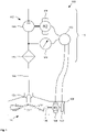
- FIG 1 shows a schematic representation of a vacuum cleaner 100.
- the vacuum cleaner 100 comprises a processing head 105, which is connected to a device unit 115 via a suction hose 110.
- the processing head 105 includes an inlet opening 120 through which an air flow 125 can enter and be directed through the suction hose 110 into the device unit 115 .
- the inlet opening 120 can be guided over a surface to be processed, so that the air flow 125 can entrain dust or dirt particles and remove them from the surface.
- the processing head 105 includes a brush 130 which can be moved by means of a drive device 135 .
- the brush 130 can be designed as a brush or brush roller, as shown by way of example. Other variations include a moveable broom or mop.
- the brush 130 is typically guided in a cyclic motion. This can be rotating or oscillating, for example.
- the brush 130 is configured to rotate about an axis of rotation that is typically parallel to the surface to be cleaned.
- the brush 130 may be rotatable about an axis of rotation that is substantially perpendicular to the surface.
- the brush 130 can take different positions. In this case, the brush 130 lies in at least one position, at least in sections, in the air flow 125.
- the drive device 135 can, for example, comprise an electric motor.
- the drive device 135 can be coupled to the brush 130 directly or by means of a step-up or step-down gear.
- a position sensor 140 can be used to determine a position of the brush 130 or the drive device 135 be provided.
- the drive device 135 can be embodied as a brushless direct current motor (BLDC), with the position sensor 140 reflecting a position of the electric motor.
- BLDC brushless direct current motor
- the device unit 115 includes an optional filter 145 for separating contaminants from the air flow 125 and a suction device 150, which in the present case includes a turbine 155 and a drive motor 160, which is preferably embodied electrically.
- An optional pneumatic sensor 165 is configured to determine a pneumatic pressure of the airflow 125 .
- the static pressure is preferably determined, but the dynamic pressure or a combination of both pressures can also be determined.
- the determined pressure may be determined with reference to the pressure of an environment from which the airflow 125 is drawn.
- the sensor 165 is arranged downstream of the inlet opening 120 and upstream of the suction device 150 . If a filter 145 is provided, the sensor 165 is preferably located downstream of the filter 145.
- a control or processing device 170 is set up to control the vacuum cleaner 100.
- the processing device 170 can control the drive device 135 . To do this, it can evaluate a position signal from position sensor 140, a signal from pneumatic sensor 165, or a signal that indicates power consumption by drive motor 160.
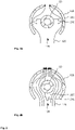
- figure 2 shows sectional views of a processing head 105 of a vacuum cleaner 100.
- a selected sectional plane is perpendicular to the axis of rotation of the brush 130, which is designed as a brush roller, for example.
- Figure 2A Figure 1 shows the brush 130 in an unfavorable first position in which the air flow 125 is significantly impeded.
- Figure 2B 12 shows the brush 130 in a second position in which the airflow 125 is minimally or not at all obstructed.
- the brush 130 shown comprises two passages or streams 205 which are guided in a helical shape along the axis of rotation.
- the flutes 205 are offset from one another by approximately 180° with respect to the axis of rotation.
- the streams 205 carry bristles 210, which can also be designed as brushes, hair, elastic nubs or other processing instruments.
- FIG. 1 shows a brush 130 designed as a bristle roller and an exemplary course of flow velocities of an air stream 125.
- the brush 130 is as in the embodiments of FIG figures 1 and 2 designed as a brush roller with an axis of rotation 305.
- the brush roller 130 includes, for example, two essentially equally long axial sections 310 and 315, on which the flows 205 have different directions of rotation. A reversal of the direction of rotation of a flute 205 therefore takes place in the area of an axial center of the brush roller 130. In the lateral view, the bristles therefore appear to be arranged in a sinusoidal manner. An embodiment without reversing the direction of rotation or with several reversing the direction of rotation is also possible.
- a profile 320 of flow velocities of the air flow 125 along the axis of rotation 305 in the area of the inlet opening 120 can be indicated.
- curve 320 shown an axial length of the brush 130 is plotted in the horizontal direction and a flow velocity in the vertical direction.
- the flow rate of the air stream 125 is highest in the middle area. From there it drops symmetrically to the right and left.
- the shape of the descending curve depends on a given geometry of the brush 130 and the processing head 105 .
- maximum flow speeds can also be achieved in axial end areas, while a lower flow speed prevails in a middle area. If the streams 205 each follow a helix without reversing the direction of rotation, the maximum of the flow velocity can be shifted along the axis of rotation 305 by rotating the brush 130 . In some positions more than one maximum can arise. The maxima have axial distances that can depend on a gradient of the tides 205 .
- figure 4 12 shows a flowchart of a method 400 for controlling a vacuum cleaner 100.
- a request to stop a movement of the brush 130 is detected. This requirement can be given by a user of the vacuum cleaner 100 and can be given, for example, for reasons of volume or a subsurface to be processed.
- the drive device 135 can then be switched off so that the brush 130 runs out and finally comes to a standstill.
- a moving speed of the brush 130 may also be successively reduced to assist in stopping at the predetermined position.
- the brush 130 comes to rest precisely at the predetermined position. This approach typically requires knowledge of the position of the brush 130 and the ability to sensitively control a speed or torque provided by the driver 135 .
- the position may be determined based on a vacuum that results in response to the position of the brush 130 in the processing head 105 downstream of the brush 130 .
- the negative pressure can be determined on the basis of a power consumption of the drive motor 160 of the suction device 150 .
- a step 410 it may be determined that the brush 130 has come to a standstill.
- the position of the brush 130 can be determined again.
- a step 420 it can be checked whether the assumed position corresponds to the predetermined position by less than a predetermined amount. If this is the case, the predetermined position can be considered to have been taken.
- the drive device 135 can be controlled in a step 425 to fix the position of the brush 130 . If the drive device 135 is an electric motor, its windings can be short-circuited, for example. If the position of the drive device 135 or of the brush 130 can be determined by means of a position sensor 140, a movement of the drive device 135 by the brush 130 can be actively counteracted by the drive device 135 being actuated appropriately.
- step 420 can branch into step 425 in any case.
- FIG 5 12 shows an example cordless vacuum cleaner 500 according to the functional schematic of vacuum cleaner 100 of FIG figure 1 .
- the vacuum cleaner 500 is shown here without the processing head 105, which can be attached to a suction socket 505 either directly or via a suction hose 110 or a suction pipe.
- the vacuum cleaner 500 is preferably operated using electrical energy from an energy store 510 .
- the cordless vacuum cleaner 500 can be used in several different configurations, which can include additional accessories.
- Exemplary accessories include suction hoses 110 of different lengths or suction pipes, a suction brush, a crevice nozzle, an upholstery nozzle or a combined suction-wipe nozzle.
- Such a device is also known under the designation Multi Use Handstick (MUH).
- the vacuum cleaner 500 can also be wired.
- FIG 6 a floor cultivating machine 600 according to the scheme of the vacuum cleaner 100 from figure 1 in an exemplary embodiment.
- the floor treatment machine 600 comprises a treatment head 105 and a suction device 150 and is set up to drive over a floor area in a household autonomously and to treat the floor traveled over by means of the suction device 150 .
- Internal elements such as an energy store 510 or a controller for motion control are not shown.
Landscapes
- Engineering & Computer Science (AREA)
- Mechanical Engineering (AREA)
- Nozzles For Electric Vacuum Cleaners (AREA)
Abstract
Description
- Die Erfindung betrifft einen Staubsauger mit Bearbeitungskopf. Insbesondere betrifft die Erfindung die Steuerung eines Bearbeitungskopfs, der eine Eintrittsöffnung für einen Luftstrom und eine im Luftstrom liegende, bewegbare Bürste umfasst.
- Ein Staubsauger umfasst eine Saugeinrichtung, die einen Luftstrom durch eine Eintrittsöffnung bewirkt. Die Eintrittsöffnung kann an einem Bearbeitungskopf angebracht sein, der über eine zu reinigende Fläche wie einen Fußboden, ein Polstermöbel oder einen Teppich geführt werden kann. Im Bereich der Eintrittsöffnung kann eine Borstenwalze vorgesehen sein, die angetrieben werden kann, um einen Untergrund mechanisch zu bearbeiten und Schmutzpartikel aus diesem zu lösen.
- Zum Reinigen unterschiedlicher Flächen ist die Borstenwalze nicht immer erforderlich. Beispielsweise kann die Borstenwalze beim Reinigen eines Teppichs angetrieben werden, während sie beim Reinigen eines parkettierten Bodens abgestellt sein kann. Steht die Borstenwalze still, so kann sie derart im Luftstrom liegen, sodass dieser unvorteilhaft verteilt oder teilweise blockiert werden kann.
- Eine der vorliegenden Erfindung zu Grunde liegende Aufgabe besteht in der Angabe einer verbesserten Technik zur Reinigung eines Untergrunds mittels eines Staubsaugers. Die Erfindung löst dieses Problem mittels der Gegenstände der unabhängigen Ansprüche. Unteransprüche geben bevorzugte Ausführungsformen wieder.
- Ein Staubsauger umfasst einen Bearbeitungskopf, der eine Eintrittsöffnung für einen Luftstrom und eine mittels der Antriebseinrichtung bewegbare Bürste umfasst. Ein Verfahren zum Steuern des Staubsaugers umfasst Schritte des Abstellens der Antriebseinrichtung derart, dass die stillstehende Bürste eine vorbestimmte Position einnimmt.
- Die bewegbare Bürste kann Borsten, Haare oder flexible Fortsätze aufweisen, die nach Art einer Bürste, eines Besens oder eines Schrubbers arbeiten können. Es wurde erkannt, dass die stillstehende Bürste bezüglich eines passierenden Luftstroms bzw. deren Verteilung über die Bürste in unterschiedlich günstigen Positionen bezüglich des Luftstroms angehalten werden kann. Es wird daher vorgeschlagen, beim Abstellen der Antriebseinrichtung dafür zu sorgen, dass die Bürste in einer vorbestimmten, vorteilhaften Position zum Stillstand kommt. Ein Saugergebnis kann dadurch verbessert sein. Außerdem kann eine Energieeffizienz einer Saugeinrichtung erhöht sein.
- In einer ersten Variante behindert die Bürste in der vorbestimmten Position den Luftstrom nur minimal. Üblicherweise kann die Bürste in einer zyklischen Bewegung geführt werden, beispielsweise in Form einer Rotation um eine Drehachse. Wird die Bürste angehalten, so kann sie eine von einer Vielzahl unterschiedlicher Positionen einnehmen. Jeder Position kann das Maß einer Behinderung des Luftstroms durch die Bürste zugeordnet sein. Die Behinderung kann an einer oder mehreren der Positionen geringer als an allen anderen Positionen sein. Die Bürste kann so angehalten werden, dass sie in einer dieser minimal behindernden Positionen zum Stillstand kommt. Der Volumenstrom des Luftstroms kann dadurch maximiert sein.
- In einer zweiten Variante kann die Bürste in der vorbestimmten Position den durch die Eintrittsöffnung tretenden Luftstrom in einer vorbestimmten Weise formen. Die Eintrittsöffnung kann beispielsweise eine vorbestimmte Breite aufweisen, wobei eine Verteilung von Strömungsgeschwindigkeiten des Luftstroms über die Breite davon abhängig sein kann, in welcher Position die Bürste steht. In der vorbestimmten Position kann beispielsweise eine Strömungsgeschwindigkeit in einem mittleren Bereich der Breite höher als in Randbereichen liegen oder umgekehrt. Andere Verteilungen sind ebenfalls möglich.
- In einer Ausführungsform wird die Position der Bürste auf der Basis eines Signals eines mit der Bürste gekoppelten Positionssensors bestimmt. Durch die Verwendung eines Sensors kann die Position der Bürste besonders sicher oder besonders genau bestimmt werden. Der Positionssensor kann dazu eingerichtet sein, das Erreichen der vorbestimmten Position oder einer Vielzahl Positionen zu bestimmen. Der Sensor kann unmittelbar mit der Bürste oder einer Antriebseinrichtung für die Bürste gekoppelt sein. Es kann sich eine Mehrdeutigkeit ergeben, wenn die Position der Antriebseinrichtung nicht eindeutig mit einer Position der Bürste korreliert, beispielsweise, weil zwischen der Antriebseinrichtung und der Bürste ein Untersetzungsgetriebe vorgesehen ist. Die Mehrdeutigkeit kann mittels einer der hierin genannten Techniken aufgelöst werden. So kann beispielsweise ein Positionssensor eines BLDC-Motors, der die Bürste antreibt, vorteilhaft genutzt werden.
- In einer weiteren Ausführungsform kann die Position der stillstehenden Bürste auf der Basis eines Unterdrucks bestimmt werden, der stromabwärts der Bürste herrscht. Der pneumatische Unterdruck kann durch eine Saugeinrichtung hervorgerufen werden, die den Luftstrom durch die Eintrittsöffnung bewirkt. Üblicherweise weist ein starker Unterdruck auf einen geringen Volumenstrom und ein schwacher Unterdruck auf einen hohen Volumenstrom des Luftstroms hin. Der Unterdruck kann bezüglich einer Umgebung oder bezüglich einer Konstellation bei sich bewegender Bürste bestimmt werden. Dadurch können andere den Volumenstrom verringernde Umstände, beispielsweise ein verstopfter Filter, kompensiert werden.
- Die Position der stillstehenden Bürste kann bestimmt werden, indem eine Position der angetriebenen Bürste verfolgt und die Antriebseinrichtung zu einem passenden Zeitpunkt angehalten wird. Dazu kann vorhergesagt werden, wie lange es dauert, bis die sich in Bewegung befindliche Bürste stillsteht. Die Anhaltezeit kann von einem Bremsmoment auf die Bürste abhängig sein, das insbesondere zwischen der Bürste und einem Untergrund wirken kann. Dabei kann das Bremsmoment von einer Beschaffenheit des Untergrunds abhängig sein. Die Beschaffenheit des Untergrunds kann bestimmt werden, bevor die Antriebseinrichtung der Bürste abgestellt wird, beispielsweise optisch oder auf der Basis eines erzielten Unterdrucks der Saugeinrichtung.
- Die Position der bewegten Bürste kann auf der Basis einer Leistungsaufnahme der Antriebseinrichtung der Bürste erfolgen. Je nach Position der Bürste können sich unterschiedlich viele und/oder unterschiedlich große Eingriffselemente in Eingriff mit einem anderen Element, insbesondere einem Untergrund, befinden. Eine zur Bewegung der Bürste erforderliche Leistung kann daher von der Position der Bürste abhängig sein.
- Zur Bestimmung der Position der stillstehenden Bürste kann auch eine Leistung bestimmt werden, die zum Losbrechen der Bürste erforderlich ist. In einer Ausführungsform befindet sich die Bürste in einer vorteilhaften Position, wenn ein Losbrechmoment einen vorbestimmten Schwellenwert übersteigt. Der stillstehende Antriebsmotor kann mit einer Leistung beaufschlagt werden, der das Losbrechmoment nur dann übersteigt, wenn sich die Bürste in einer anderen Position befindet. Bewegt sich die Bürste nicht, so ist die gesuchte Position gefunden.
- Die Leistung kann an leicht direkt der Antriebseinrichtung bestimmt werden. Umfasst diese einen Elektromotor, so kann die Leistung auf der Basis einer anliegenden Spannung und/oder eines durch den Elektromotor fließenden Stroms bestimmt werden. Strom oder Spannung können mit geringem Aufwand präzise bestimmt werden.
- In noch einer weiteren Ausführungsform kann die Position der sich bewegenden Bürste auch auf der Basis einer Geräuschmessung im Bereich der Bürste bestimmt werden. Ein lauteres Geräusch der Borsten auf einem Untergrund kann darauf hinweisen, dass sich mehr oder größere Borsten in Eingriff mit dem Untergrund befinden und ein leiseres Geräusch darauf, dass weniger oder kleinere Borsten in den Untergrund eingreifen.
Wir die Bürste zyklisch bewegt, beispielsweise rotierend oder oszillierend, so kann Position der sich bewegenden Bürste verbessert bestimmt werden, indem ein mechanischer Index an der Bürste vorgesehen wird, der in einem vorbestimmten Punkt des Bewegungszyklus in gezielter Weise einen auf die Position hinweisenden Parameter beeinflusst. Beispielsweise kann in einer regelmäßigen Anordnung von Borsten an einer Stelle eine Auslassung von Borsten, zusätzliche Borsten, Borsten veränderter Größe oder veränderten Materials oder ein anderes Element als eine Borste vorgesehen sein. Der an der sich bewegenden Bürste bestimmte Parameter kann dann charakteristisch einmal pro Zyklus erhöht oder verringert sein, sodass zu diesem Zeitpunkt die Position der Bürste bekannt ist. - In wieder einer weiteren Ausführungsform kann die Position der stillstehenden Bürste auf der Basis einer Leistungsaufnahme einer Saugeinrichtung stromabwärts der Bürste bestimmt werden. Die Saugeinrichtung kann eine Turbine mit einem gekoppelten Antriebsmotor umfassen. Der Antriebsmotor kann elektrisch ausgeführt sein, wobei die Leistungsaufnahme auf der Basis eines durch den Antriebsmotor fließenden elektrischen Stroms bei bekannter Spannung bestimmt werden kann. Diese Herangehensweise kann einen zusätzlichen Sensor nicht erfordern. Die Bestimmung der Position der Bürste kann daher besonders robust erfolgen.
- In noch einer weiteren Ausführungsform wird die Bürste in einer unspezifizierten, beliebigen oder zufälligen Position angehalten und vorübergehend erneut angetrieben, falls die stillstehende Bürste um mehr als ein vorbestimmtes Maß von der bestimmten Position abweicht. Anders ausgedrückt kann eine Antriebseinrichtung der Bürste ohne Rücksicht auf eine voraussichtliche Anhalteposition abgestellt werden und die durch die Bürste eingenommene Position kann erst nach ihrem Anhalten bestimmt werden. Sollte die vorbestimmte Position nicht genau genug getroffen sein, so kann die Bürste erneut bewegt werden, um ihre Position zu ändern. Um eine Endlosschleife zu verhindern, kann nach einer vorbestimmten Anzahl Versuche, beispielsweise nach drei oder fünf Mal, auf ein weiteres Antreiben der Bürste verzichtet werden. Auch diese Ausführungsform benötigt keinen zusätzlichen Sensor und kann an einem bestehenden Staubsauger ohne Änderungen einsetzbar sein. Eine Realisierung dieser Ausführungsform kann besonders einfach sein.
- Es ist zu beachten, dass auch mehrere hierin beschriebene Möglichkeiten zur Bestimmung der Position der Bürste miteinander kombiniert werden können. Dabei kann auch ein dynamisches Verfahren, das die Position der sich bewegenden Bürste und eine Modellierung eines Anhalteverhaltens verwendet, mit einem statischen Verfahren, das die Position der stillstehenden Bürste direkt bestimmt, kombiniert werden.
- Die Antriebseinrichtung kann dazu angesteuert werden, die stillstehende Bürste in ihrer Position zu halten. Eine Bewegung der Bürste gegenüber einem Untergrund im Rahmen der Verwendung des Staubsaugers kann dadurch nicht zum Ändern der Position der Bürste im Bearbeitungskopf führen.
- Nach einem weiteren Aspekt der vorliegenden Erfindung umfasst ein Bearbeitungskopf für einen Staubsauger eine Eintrittsöffnung für einen Luftstrom; eine bewegbare Bürste; eine Antriebseinrichtung zur Bewegung der Bürste im Luftstrom; und eine Verarbeitungseinrichtung, die dazu eingerichtet ist, die Antriebseinrichtung derart abzustellen, dass sich die stillstehende Bürste in einer vorbestimmten Position befindet.
- Die Bürste ist bevorzugt stromabwärts der Eintrittsöffnung angeordnet. Die Verarbeitungseinrichtung kann dazu eingerichtet sein, ein hierin beschriebenes Verfahren ganz oder teilweise auszuführen. Dazu kann das Verfahren in Form eines Computerprogrammprodukts mit Programmcodemitteln vorliegen. Die Verarbeitungseinrichtung kann einen programmierbaren Mikrocomputer oder Mikrocontroller umfassen. Merkmale oder Vorteile des Bearbeitungskopfs können auf das Verfahren übertragen werden oder umgekehrt.
- Am Bearbeitungskopf kann ein mit der Bürste gekoppelter Positionssensor vorgesehen sein. Der Positionssensor ist dazu eingerichtet, ein Signal bereitzustellen, das auf eine Position der Bürste hinweist. Dabei kann der Positionssensor die Position der Bürste oder die der Antriebseinrichtung bereitstellen. Die Antriebseinrichtung kann mittels eines Getriebes mit der Bürste gekoppelt sein. In einer Ausführungsform umfasst die Antriebseinrichtung einen Elektromotor, mit dem der Positionssensor gekoppelt ist, um das Drehverhalten des Motors zu steuern. Die Steuerung kann feldorientiert erfolgen (feldorienterte Steuerung, Vektorsteuerung). Der Motor kann insbesondere einen bürstenlosen Gleichstrommotor (brushless direct current, BLDC) umfassen.
- In einer weiteren Ausführungsform ist ein Sensor zur Bestimmung eines pneumatischen Drucks stromabwärts der Bürste vorgesehen. Der Sensor ist bevorzugt stromaufwärts einer Saugeinrichtung vorgesehen. Umfasst der Staubsauger einen Filter, so kann der Sensor zwischen dem Filter und der Saugeinrichtung vorgesehen sein, sodass er ein Signal bereitstellen kann, das auf einen Füllungsgrad des Filters hinweist.
- Nach wieder einem weiteren Aspekt der vorliegenden Erfindung umfasst ein Staubsauger einen hierin beschriebenen Bearbeitungskopf und eine Saugeinrichtung stromabwärts der Bürste. Der Staubsauger kann als stationärer Staubsauger, Handstaubsauger, als Bodenstaubsauger mit einem Schlauch, als Hand- oder Rüsselstaubsauger mit einem Rohr oder als Hand- oder Stabstaubsauger ausgeführt sein. Andere Varianten sind ebenfalls möglich. Der Staubsauger ist dazu eingerichtet, in einem zu reinigenden Bereich einen Luftstrom bereitzustellen, der Staub und kleine Schmutzpartikel mitreißt.
- Die Verarbeitungseinrichtung kann dazu eingerichtet sein, ein hierin beschriebenes Verfahren ganz oder teilweise auszuführen. Dazu kann die Verarbeitungseinrichtung einen programmierbaren Mikrocomputer oder Mikrocontroller umfassen und das Verfahren kann in Form eines Computerprogrammprodukts mit Programmcodemitteln vorliegen. Das Computerprogrammprodukt kann auch auf einem computerlesbaren Datenträger abgespeichert sein. Merkmale oder Vorteile des Verfahrens können auf die Vorrichtung übertragen werden oder umgekehrt.
- Die Erfindung wird nun unter Bezug auf die beiliegenden Figuren genauer beschrieben, in denen:
- Figur 1
- eine schematische Darstellung eines Stausaugers;
- Figur 2
- Schnittansichten eines Bearbeitungskopfes eines Staubsaugers;
- Figur 3
- eine Bürste und einen Verlauf von Geschwindigkeiten eines Luftstroms;
- Figur 4
- ein Ablaufdiagramm eines Verfahrens zum Steuern eines Staubsaugers;
- Figur 5
- einen beispielhaften kabellosen Staubsauger; und
- Figur 6
- eine Bodenbearbeitungsmaschine in einer beispielhaften Ausführungsform darstellt.
-
Figur 1 zeigt eine schematische Darstellung eines Stausaugers 100. In der dargestellten, beispielhaften Ausführungsform umfasst der Stausauger 100 einen Bearbeitungskopf 105, der über einen Saugschlauch 110 mit einer Geräteeinheit 115 verbunden ist. Der Bearbeitungskopf 105 umfasst eine Eintrittsöffnung 120, durch die ein Luftstrom 125 eintreten und durch den Saugschlauch 110 in die Geräteeinheit 115 geleitet werden kann. Die Eintrittsöffnung 120 kann über eine zu bearbeitende Fläche geführt werden, sodass der Luftstrom 125 Staub oder Schmutzpartikel mitreißen und von der Fläche entfernen kann. - Der Bearbeitungskopf 105 umfasst eine Bürste 130, die mittels einer Antriebseinrichtung 135 bewegt werden kann. Die Bürste 130 kann wie beispielhaft dargestellt ist als Bürsten-oder Borstenwalze ausgeführt sein. Andere Varianten umfassen einen beweglichen Besen oder Schrubber. Die Bürste 130 wird üblicherweise in einer zyklischen Bewegung geführt. Diese kann beispielsweise rotierend oder oszillierend sein. In der dargestellten Ausführungsform ist die Bürste 130 zum Rotieren um eine Drehachse eingerichtet, die üblicherweise parallel zur zu reinigenden Fläche verläuft. In einer anderen Ausführungsform kann die Bürste 130 um eine Drehachse drehbar sein, die im Wesentlichen senkrecht auf der Fläche steht. Die Bürste 130 kann unterschiedliche Positionen einnehmen. Dabei liegt die Bürste 130 in zumindest einer Position zumindest abschnittsweise im Luftstrom 125. Die Antriebseinrichtung 135 kann beispielsweise einen Elektromotor umfassen. Die Antriebseinrichtung 135 kann direkt oder mittels eines Über-oder Untersetzungsgetriebes mit der Bürste 130 gekoppelt sein. Ein Positionssensor 140 kann zur Bestimmung einer Position der Bürste 130 oder der Antriebseinrichtung 135 vorgesehen sein. Die Antriebseinrichtung 135 kann als bürstenloser Gleichstrommotor (BLDC) ausgeführt sein, wobei der Positionssensor 140 eine Position des Elektromotors reflektiert.
- Die Geräteeinheit 115 umfasst einen optionalen Filter 145 zur Abscheidung von Verunreinigungen aus dem Luftstrom 125 und eine Saugeinrichtung 150, die vorliegend eine Turbine 155 und einen Antriebsmotor 160 umfasst, der bevorzugt elektrisch ausgeführt ist. Ein optionaler pneumatischer Sensor 165 ist dazu eingerichtet, einen pneumatischen Druck des Luftstroms 125 zu bestimmen. Bevorzugt wird der statische Druck bestimmt, es kann jedoch auch der dynamische Druck oder eine Kombination beider Drücke bestimmt werden. Der bestimmte Druck kann mit Bezug auf den Druck einer Umgebung, aus der der Luftstrom 125 eingesaugt wird, bestimmt werden. Der Sensor 165 ist stromabwärts der Eintrittsöffnung 120 und stromaufwärts der Saugeinrichtung 150 angeordnet. Ist ein Filter 145 vorgesehen, so befindet sich der Sensor 165 bevorzugt stromabwärts des Filters 145. Eine Steuer- oder Verarbeitungseinrichtung 170 ist dazu eingerichtet, den Stausauger 100 zu steuern. Insbesondere kann die Verarbeitungseinrichtung 170 die Antriebseinrichtung 135 steuern. Dazu kann sie ein Positionssignal des Positionssensors 140, ein Signal des pneumatischen Sensors 165 oder ein Signal auswerten, das auf eine Leistungsaufnahme des Antriebsmotors 160 hinweist.
-
Figur 2 zeigt Schnittansichten eines Bearbeitungskopfes 105 eines Staubsaugers 100. Eine gewählte Schnittebene erfolgt senkrecht zur Drehachse der Bürste 130, die beispielhaft als Borstenwalze ausgeführt ist.Figur 2A zeigt die Bürste 130 in einer unvorteilhaften ersten Position, in welcher der Luftstrom 125 signifikant behindert ist.Figur 2B zeigt die Bürste 130 in einer zweiten Position, in welcher der Luftstrom 125 nur minimal oder gar nicht behindert ist. - Rein beispielhaft umfasst die dargestellte Bürste 130 zwei Gänge oder Fluten 205, die entlang der Drehachse helixförmig geführt sind. Dabei sind die Fluten 205 bezüglich der Drehachse um ca. 180° gegeneinander versetzt. An radial äußeren Enden tragen die Fluten 205 Borsten 210, die auch als Pinsel, Haare, elastische Noppen oder andere Bearbeitungsinstrumente ausgeführt sein können.
- Es ist zu erkennen, dass in der Position von
Figur 2A ein deutlich geringerer Luftstrom 125 durch den Bearbeitungskopf 105 treten kann als in der inFigur 2B gezeigten Position. Welche Position der Bürste 130 gegenüber dem Bearbeitungskopf 105 förderlich für den Luftstrom 125 oder seine Verteilung entlang der Eintrittsöffnung 120 ist, kann von jeweiligen Geometrien abhängig sein. Allgemein gilt, dass zum Erreichen einer hohen Strömungsgeschwindigkeit ein möglichst großer Strömungsquerschnitt bereitgestellt sein sollte. -
Figur 3 zeigt eine beispielhaft als Borstenwalze ausgeführte Bürste 130 und einen beispielhaften Verlauf von Strömungsgeschwindigkeiten eines Luftstroms 125. Die Bürste 130 ist wie in den Ausführungsformen derFiguren 1 und2 als Borstenwalze mit einer Drehachse 305 ausgeführt. Die Borstenwalze 130 umfasst exemplarisch zwei im Wesentlichen gleich lange axiale Abschnitte 310 und 315, auf denen die Fluten 205 unterschiedliche Drehrichtungen aufweisen. Eine Drehrichtungsumkehr einer Flute 205 erfolgt also im Bereich einer axialen Mitte der Borstenwalze 130. In der seitlichen Ansicht erscheinen die Borsten daher sinusförmig angeordnet. Eine Ausführungsform ohne Drehrichtungsumkehr oder mit mehreren Drehrichtungsumkehren ist ebenfalls möglich. - Unter beispielhafter Voraussetzung eines Bearbeitungskopfs 105, der ähnlich wie in
Figur 2 dargestellt ausgeführt ist, kann ein Verlauf 320 von Strömungsgeschwindigkeiten des Luftstroms 125 entlang der Drehachse 305 im Bereich der Eintrittsöffnung 120 angegeben werden. Für den dargestellten, beispielhaften Verlauf 320 ist in horizontaler Richtung eine axiale Länge der Bürste 130 und in vertikaler Richtung eine Strömungsgeschwindigkeit angetragen. In der dargestellten Position der Bürste 130 ist die Strömungsgeschwindigkeit des Luftstroms 125 im mittleren Bereich am höchsten. Von dort fällt er symmetrisch nach rechts und links gleich ab. Die Form der abfallenden Kurve ist von einer vorliegenden Geometrie der Bürste 130 und des Bearbeitungskopfs 105 abhängig. Wird die Bürste 130 in eine andere Position um die Drehachse 305 gebracht, so können maximale Strömungsgeschwindigkeiten auch in axialen Endbereichen erzielt werden, während in einem mittleren Bereich eine geringere Strömungsgeschwindigkeit herrscht. Folgen die Fluten 205 jeweils einer Helix ohne Drehrichtungsumkehr, so kann das Maximum der Strömungsgeschwindigkeit entlang der Drehachse 305 verschoben werden, indem die Bürste 130 gedreht wird. In machen Positionen können mehr als ein Maximum entstehen. Die Maxima haben axiale Abstände, die von einer Steigung der Fluten 205 abhängig sein können. -
Figur 4 zeigt ein Ablaufdiagramm eines Verfahrens 400 zur Steuerung eines Staubsaugers 100. In einem Schritt 405 wird eine Anforderung erfasst, eine Bewegung der Bürste 130 einzustellen. Diese Anforderung kann von einem Benutzer des Stausaugers 100 gegeben sein und beispielsweise aus Gründen der Lautstärke oder eines zu bearbeitenden Untergrunds gegeben sein. Daraufhin kann die Antriebseinrichtung 135 abgestellt werden, sodass die Bürste 130 ausläuft und schließlich zum Stillstand kommt. Eine Bewegungsgeschwindigkeit der Bürste 130 kann auch sukzessive verringert werden, um das Anhalten in der vorbestimmten Position zu unterstützen. Bevorzugt erreicht die Bürste 130 genau in der vorbestimmten Position ihren Stillstand. Diese Herangehensweise erfordert üblicherweise die Kenntnis der Position der Bürste 130 und die Möglichkeit, eine Drehzahl oder ein bereitgestelltes Drehmoment der Antriebseinrichtung 135 feinfühlig zu steuern. - In einer Ausführungsform kann die Position auf der Basis eines Unterdrucks bestimmt werden, der sich in Antwort auf die Position der Bürste 130 im Bearbeitungskopf 105 stromabwärts der Bürste 130 ergibt. Der Unterdruck kann auf der Basis einer Stromaufnahme des Antriebsmotors 160 der Saugeinrichtung 150 bestimmt werden.
- In einem Schritt 410 kann bestimmt werden, dass die Bürste 130 den Stillstand erreicht hat. In einem Schritt 415 kann die Position der Bürste 130 erneut bestimmt werden. In einem Schritt 420 kann geprüft werden, ob die eingenommene Position um weniger als ein vorbestimmtes Maß der vorbestimmten Position entspricht. Ist dies der Fall, so kann die vorbestimmte Position als eingenommen gelten.
- Ist dies der Fall, so kann die Antriebseinrichtung 135 in einem Schritt 425 dazu angesteuert werden, die Position der Bürste 130 zu fixieren. Handelt es sich bei der Antriebseinrichtung 135 um einen Elektromotor, so können dessen Windungen beispielsweise kurzgeschlossen werden. Kann die Position der Antriebseinrichtung 135 oder der Bürste 130 mittels eines Positionssensors 140 bestimmt werden, so kann einer Bewegung der Antriebseinrichtung 135 durch die Bürste 130 aktiv entgegengewirkt werden, indem die Antriebseinrichtung 135 passend angesteuert wird.
- Sollte im Schritt 420 bestimmt worden sein, dass die vorbestimmte Position nicht eingenommen wurde, so kann die Antriebseinrichtung 135 in einem Schritt 430 erneut und für einen vorbestimmten Zeitabschnitt aktiviert werden. Anschließend kann das Verfahren 400 zum Schritt 405 zurückkehren und erneut durchlaufen. Sollte die vorbestimmte Position auch nach einer vorbestimmten Anzahl Durchläufe durch den Schritt 430 nicht eingenommen worden sein, so kann aus dem Schritt 420 in jedem Fall in den Schritt 425 verzweigt werden.
-
Figur 5 zeigt einen beispielhaften kabellosen Staubsauger 500 nach dem funktionalen Schema des Staubsaugers 100 vonFigur 1 . Der Staubsauger 500 ist vorliegend ohne den Bearbeitungskopf 105 dargestellt, der entweder direkt oder über einen Saugschlauch 110 oder ein Saugrohr an einem Saugstutzen 505 angebracht werden kann. Der Staubsauger 500 wird bevorzugt mittels elektrischer Energie aus einem Energiespeicher 510 betrieben. - In einer bevorzugten Ausführungsform kann der kabellose Staubsauger 500 in mehreren unterschiedlichen Konfigurationen verwendet werden, die weitere Zubehörteile umfassen können. Beispielhafte Zubehörteile umfassen unterschiedlich lange Saugschläuche 110 oder Saugrohre, eine Saugbürste, eine Fugendüse, eine Polsterdüse oder eine kombinierte Saug-Wisch-Düse. Ein solches Gerät ist auch unter der Bezeichnung Multi Use Handstick (MUH) bekannt. In einer anderen Ausführungsform kann der Staubsauger 500 auch kabelgebunden ausgeführt sein.
-
Figur 6 eine Bodenbearbeitungsmaschine 600 nach dem Schema des Staubsaugers 100 vonFigur 1 in einer beispielhaften Ausführungsform. Die Bodenbearbeitungsmaschine 600 umfasst einen Bearbeitungskopf 105 und eine Saugeinrichtung 150 und ist dazu eingerichtet, eine Bodenfläche in einem Haushalt autonom zu befahren und den befahrenen Boden mittels der Saugeinrichtung 150 zu bearbeiten. Interne Elemente wie ein Energiespeicher 510 oder eine Steuervorrichtung zur Bewegungssteuerung sind nicht dargestellt. -
- 100
- Staubsauger
- 105
- Bearbeitungskopf
- 110
- Saugschlauch
- 115
- Geräteeinheit
- 120
- Eintrittsöffnung
- 125
- Luftstrom
- 130
- Bürste
- 135
- Antriebseinrichtung
- 140
- Positionssensor
- 145
- Filter
- 150
- Saugeinrichtung
- 155
- Turbine
- 160
- Antriebsmotor
- 165
- pneumatischer Sensor
- 170
- Verarbeitungseinrichtung
- 205
- Flute, Gang
- 210
- Borste
- 305
- Drehachse
- 310
- erster Abschnitt
- 315
- zweiter Abschnitt
- 320
- Verlauf
- 400
- Verfahren
- 405
- Antriebseinrichtung abstellen
- 410
- Stillstand abwarten
- 415
- Position bestimmen
- 420
- Position korrekt?
- 425
- Position halten
- 430
- erneut anstellen
- 500
- Staubsauger
- 505
- Saugstutzen
- 510
- Energiespeicher
- 600
- Bodenbearbeitungsmaschine
Claims (15)
- Verfahren (400) zum Steuern eines Staubsaugers (100, 500, 600) mit einem Bearbeitungskopf (105), wobei der Bearbeitungskopf (105) eine Eintrittsöffnung (120) für einen Luftstrom (125) und eine mittels einer Antriebseinrichtung (135) bewegbare Bürste (130) umfasst, wobei das Verfahren (400) folgende Schritte umfasst:- Abstellen der Antriebseinrichtung (135) derart, dass die stillstehende Bürste (130) eine vorbestimmte Position einnimmt.
- Verfahren (400) nach Anspruch 1, wobei die Bürste (130) in der vorbestimmten Position den Luftstrom (125) minimal behindert.
- Bearbeitungskopf (105) nach Anspruch 1 oder 2, wobei die Bürste (130) in der vorbestimmten Position den durch die Eintrittsöffnung (120) tretenden Luftstrom (125) in einer vorbestimmten Weise formt.
- Verfahren (400) nach einem der vorangehenden Ansprüche, wobei die Position der Bürste (130) auf der Basis eines Signals eines mit der Bürste (130) gekoppelten Positionssensors (140) bestimmt wird.
- Verfahren (400) nach einem der vorangehenden Ansprüche, wobei die Position der stillstehenden Bürste (130) auf der Basis eines Unterdrucks bestimmt wird, der stromabwärts der Bürste (130) herrscht.
- Verfahren (400) nach einem der vorangehenden Ansprüche, wobei die Position der Bürste (130) auf der Basis einer Leistungsaufnahme an der Antriebseinrichtung (135) erfolgt.
- Verfahren (400) nach einem der vorangehenden Ansprüche, wobei die Position der Bürste (130) auf der Basis einer Geräuschmessung im Bereich der Bürste (130) bestimmt wird.
- Verfahren (400) nach einem der vorangehenden Ansprüche, wobei die Position der stillstehenden Bürste (130) auf der Basis einer Leistungsaufnahme einer Saugeinrichtung (150) stromabwärts der Bürste (130) bestimmt wird.
- Verfahren (400) nach einem der vorangehenden Ansprüche, wobei die Bürste (130) in einer unspezifizierten Position angehalten wird; und vorübergehend erneut angetrieben wird, falls die stillstehende Bürste (130) um mehr als ein vorbestimmtes Maß von der bestimmten Position abweicht.
- Verfahren (400) nach einem der vorangehenden Ansprüche, wobei die Antriebseinrichtung (135) dazu angesteuert wird, die stillstehende Bürste (130) in ihrer Position zu halten.
- Bearbeitungskopf (105) für einen Staubsauger (100, 500, 600), umfassend:- eine Eintrittsöffnung (120) für einen Luftstrom (125);- eine bewegbare Bürste (130);- eine Antriebseinrichtung (135) zur Bewegung der Bürste (130) im Luftstrom (125); und- eine Verarbeitungseinrichtung (170), die dazu eingerichtet ist, die Antriebseinrichtung (135) derart abzustellen, dass sich die stillstehende Bürste (130) in einer vorbestimmten Position befindet.
- Bearbeitungskopf (105) nach Anspruch 11, ferner umfassend einen mit der Bürste (130) gekoppelten Positionssensor (140).
- Bearbeitungskopf (105) nach Anspruch 11 oder 12, ferner umfassend einen Sensor (165) zur Bestimmung eines pneumatischen Drucks stromabwärts der Bürste (130).
- Staubsauger (100, 500), umfassend einen Bearbeitungskopf (105) nach einem der Ansprüche 11 bis 13, ferner umfassend eine Saugeinrichtung (150) stromabwärts der Bürste (130).
- Bodenbearbeitungsmaschine (100, 600), umfassend einen Bearbeitungskopf (105) nach einem der Ansprüche 11 bis 13 und eine Saugeinrichtung (150) stromabwärts der Bürste (130).
Applications Claiming Priority (1)
| Application Number | Priority Date | Filing Date | Title |
|---|---|---|---|
| DE102020212045.5A DE102020212045B4 (de) | 2020-09-24 | 2020-09-24 | Staubsauger mit Bearbeitungskopf |
Publications (2)
| Publication Number | Publication Date |
|---|---|
| EP3973837A1 true EP3973837A1 (de) | 2022-03-30 |
| EP3973837B1 EP3973837B1 (de) | 2023-08-30 |
Family
ID=77666364
Family Applications (1)
| Application Number | Title | Priority Date | Filing Date |
|---|---|---|---|
| EP21195514.1A Active EP3973837B1 (de) | 2020-09-24 | 2021-09-08 | Staubsauger mit bearbeitungskopf |
Country Status (2)
| Country | Link |
|---|---|
| EP (1) | EP3973837B1 (de) |
| DE (1) | DE102020212045B4 (de) |
Families Citing this family (1)
| Publication number | Priority date | Publication date | Assignee | Title |
|---|---|---|---|---|
| DE102023208109A1 (de) * | 2023-08-24 | 2025-02-27 | BSH Hausgeräte GmbH | Bürstenwalze, Reinigungseinheit und Verfahren zum Abdichten eines Saugmunds |
Citations (2)
| Publication number | Priority date | Publication date | Assignee | Title |
|---|---|---|---|---|
| DE19805900C1 (de) * | 1998-02-13 | 1999-07-29 | Duepro Ag | Saugreinigungswerkzeug mit ausschwenkbarer Bürstenwalze |
| EP2811883A1 (de) * | 2012-02-08 | 2014-12-17 | Dyson Technology Limited | Reinigungskopf für einen staubsauger |
Family Cites Families (2)
| Publication number | Priority date | Publication date | Assignee | Title |
|---|---|---|---|---|
| DE202007017026U1 (de) | 2007-12-06 | 2009-04-09 | Vorwerk & Co. Interholding Gmbh | Bodenreinigungsgerät mit einer Reinigungswalze |
| DE102017116363A1 (de) | 2017-07-20 | 2019-01-24 | Vorwerk & Co. Interholding Gmbh | Bodenbearbeitungsgerät mit einem motorisch angetriebenen Bodenbearbeitungselement |
-
2020
- 2020-09-24 DE DE102020212045.5A patent/DE102020212045B4/de not_active Expired - Fee Related
-
2021
- 2021-09-08 EP EP21195514.1A patent/EP3973837B1/de active Active
Patent Citations (2)
| Publication number | Priority date | Publication date | Assignee | Title |
|---|---|---|---|---|
| DE19805900C1 (de) * | 1998-02-13 | 1999-07-29 | Duepro Ag | Saugreinigungswerkzeug mit ausschwenkbarer Bürstenwalze |
| EP2811883A1 (de) * | 2012-02-08 | 2014-12-17 | Dyson Technology Limited | Reinigungskopf für einen staubsauger |
Also Published As
| Publication number | Publication date |
|---|---|
| DE102020212045B4 (de) | 2023-06-29 |
| EP3973837B1 (de) | 2023-08-30 |
| DE102020212045A1 (de) | 2022-03-24 |
Similar Documents
| Publication | Publication Date | Title |
|---|---|---|
| DE102010000573B4 (de) | Verfahren zur Leistungssteuerung eines Saug-/Kehrgeräts | |
| DE202016001757U1 (de) | Agitator und Reinigungsroboter mit diesem | |
| DE10262191A1 (de) | Mobiles Bodenbearbeitungsgerät | |
| DE10302525A1 (de) | Saugvorrichtung eines Reinigers | |
| EP2893860B1 (de) | Bodenpflegegerät mit einer angetriebenen Bürstenwalze | |
| EP3023032A1 (de) | Seitenbürste für einen saugroboter und saugroboter mit einer seitenbürste | |
| DE102016110817A1 (de) | Saugroboter mit seitlichen Saugrüsseln | |
| EP3973837B1 (de) | Staubsauger mit bearbeitungskopf | |
| EP3443863B1 (de) | Bürste für ein selbstfahrendes bodenreinigunsgerät | |
| DE102012104706A1 (de) | Saugdüse mit zwei Saugmündern | |
| EP2939581B1 (de) | Selbstfahrendes reinigungsgerät und betriebsverfahren für ein selbstfahrendes reinigungsgerät | |
| DE102015114082A1 (de) | Saugroboter mit rotierender Borstwalze und Verfahren zum Reinigen einer Borstwalze eines Saugroboters | |
| EP4260756A1 (de) | Reinigungsgerät, kehrbürste für ein reinigungsgerät und verfahren zum betreiben eines reinigungsgeräts | |
| DE102023202656B4 (de) | Kombinierter Bodenroboter | |
| DE102018111845A1 (de) | Bodenpflegegerät | |
| EP2982283B1 (de) | Kombisaugsystem | |
| DE102017125085A1 (de) | Bodenpflegegerät | |
| DE102012208685A1 (de) | Düse mit einer Bürstenwalze für einen Staubsauger und Staubsauger | |
| EP4260782A1 (de) | Reinigungsgerät und kehrbürste für ein reinigungsgerät | |
| EP3586709B1 (de) | Bodendüse für staubsauger und staubsauger | |
| DE102020124062A1 (de) | Staubsauger, vorzugsweise Handstaubsauger | |
| EP4098166B1 (de) | Bodendüse für staubsauger, staubsauger, bürstenwalzenset und verfahren zum betreiben eines staubsaugers | |
| DE102019104429A1 (de) | Bodenpflegegerät und Verfahren zum Betrieb eines Bodenpflegegeräts | |
| EP2534991B1 (de) | Bodendüse für einen Staubsauger und Staubsauger mit einer solchen Bodendüse | |
| WO2019042570A1 (de) | Staubfilter für eine reinigungsmaschine mit einer filter-abreinigungseinrichtung, reinigungsmaschine, und verfahren zur herstellung eines staubfilters |
Legal Events
| Date | Code | Title | Description |
|---|---|---|---|
| PUAI | Public reference made under article 153(3) epc to a published international application that has entered the european phase |
Free format text: ORIGINAL CODE: 0009012 |
|
| STAA | Information on the status of an ep patent application or granted ep patent |
Free format text: STATUS: THE APPLICATION HAS BEEN PUBLISHED |
|
| AK | Designated contracting states |
Kind code of ref document: A1 Designated state(s): AL AT BE BG CH CY CZ DE DK EE ES FI FR GB GR HR HU IE IS IT LI LT LU LV MC MK MT NL NO PL PT RO RS SE SI SK SM TR |
|
| STAA | Information on the status of an ep patent application or granted ep patent |
Free format text: STATUS: REQUEST FOR EXAMINATION WAS MADE |
|
| 17P | Request for examination filed |
Effective date: 20220930 |
|
| RBV | Designated contracting states (corrected) |
Designated state(s): AL AT BE BG CH CY CZ DE DK EE ES FI FR GB GR HR HU IE IS IT LI LT LU LV MC MK MT NL NO PL PT RO RS SE SI SK SM TR |
|
| GRAP | Despatch of communication of intention to grant a patent |
Free format text: ORIGINAL CODE: EPIDOSNIGR1 |
|
| STAA | Information on the status of an ep patent application or granted ep patent |
Free format text: STATUS: GRANT OF PATENT IS INTENDED |
|
| RIC1 | Information provided on ipc code assigned before grant |
Ipc: A47L 9/04 20060101AFI20230320BHEP |
|
| INTG | Intention to grant announced |
Effective date: 20230414 |
|
| GRAS | Grant fee paid |
Free format text: ORIGINAL CODE: EPIDOSNIGR3 |
|
| GRAA | (expected) grant |
Free format text: ORIGINAL CODE: 0009210 |
|
| STAA | Information on the status of an ep patent application or granted ep patent |
Free format text: STATUS: THE PATENT HAS BEEN GRANTED |
|
| AK | Designated contracting states |
Kind code of ref document: B1 Designated state(s): AL AT BE BG CH CY CZ DE DK EE ES FI FR GB GR HR HU IE IS IT LI LT LU LV MC MK MT NL NO PL PT RO RS SE SI SK SM TR |
|
| REG | Reference to a national code |
Ref country code: GB Ref legal event code: FG4D Free format text: NOT ENGLISH |
|
| REG | Reference to a national code |
Ref country code: CH Ref legal event code: EP |
|
| REG | Reference to a national code |
Ref country code: DE Ref legal event code: R096 Ref document number: 502021001374 Country of ref document: DE |
|
| REG | Reference to a national code |
Ref country code: IE Ref legal event code: FG4D Free format text: LANGUAGE OF EP DOCUMENT: GERMAN |
|
| REG | Reference to a national code |
Ref country code: LT Ref legal event code: MG9D |
|
| REG | Reference to a national code |
Ref country code: NL Ref legal event code: MP Effective date: 20230830 |
|
| PG25 | Lapsed in a contracting state [announced via postgrant information from national office to epo] |
Ref country code: GR Free format text: LAPSE BECAUSE OF FAILURE TO SUBMIT A TRANSLATION OF THE DESCRIPTION OR TO PAY THE FEE WITHIN THE PRESCRIBED TIME-LIMIT Effective date: 20231201 |
|
| PG25 | Lapsed in a contracting state [announced via postgrant information from national office to epo] |
Ref country code: IS Free format text: LAPSE BECAUSE OF FAILURE TO SUBMIT A TRANSLATION OF THE DESCRIPTION OR TO PAY THE FEE WITHIN THE PRESCRIBED TIME-LIMIT Effective date: 20231230 |
|
| PG25 | Lapsed in a contracting state [announced via postgrant information from national office to epo] |
Ref country code: SE Free format text: LAPSE BECAUSE OF FAILURE TO SUBMIT A TRANSLATION OF THE DESCRIPTION OR TO PAY THE FEE WITHIN THE PRESCRIBED TIME-LIMIT Effective date: 20230830 Ref country code: RS Free format text: LAPSE BECAUSE OF FAILURE TO SUBMIT A TRANSLATION OF THE DESCRIPTION OR TO PAY THE FEE WITHIN THE PRESCRIBED TIME-LIMIT Effective date: 20230830 Ref country code: NO Free format text: LAPSE BECAUSE OF FAILURE TO SUBMIT A TRANSLATION OF THE DESCRIPTION OR TO PAY THE FEE WITHIN THE PRESCRIBED TIME-LIMIT Effective date: 20231130 Ref country code: LV Free format text: LAPSE BECAUSE OF FAILURE TO SUBMIT A TRANSLATION OF THE DESCRIPTION OR TO PAY THE FEE WITHIN THE PRESCRIBED TIME-LIMIT Effective date: 20230830 Ref country code: LT Free format text: LAPSE BECAUSE OF FAILURE TO SUBMIT A TRANSLATION OF THE DESCRIPTION OR TO PAY THE FEE WITHIN THE PRESCRIBED TIME-LIMIT Effective date: 20230830 Ref country code: IS Free format text: LAPSE BECAUSE OF FAILURE TO SUBMIT A TRANSLATION OF THE DESCRIPTION OR TO PAY THE FEE WITHIN THE PRESCRIBED TIME-LIMIT Effective date: 20231230 Ref country code: HR Free format text: LAPSE BECAUSE OF FAILURE TO SUBMIT A TRANSLATION OF THE DESCRIPTION OR TO PAY THE FEE WITHIN THE PRESCRIBED TIME-LIMIT Effective date: 20230830 Ref country code: GR Free format text: LAPSE BECAUSE OF FAILURE TO SUBMIT A TRANSLATION OF THE DESCRIPTION OR TO PAY THE FEE WITHIN THE PRESCRIBED TIME-LIMIT Effective date: 20231201 Ref country code: FI Free format text: LAPSE BECAUSE OF FAILURE TO SUBMIT A TRANSLATION OF THE DESCRIPTION OR TO PAY THE FEE WITHIN THE PRESCRIBED TIME-LIMIT Effective date: 20230830 |
|
| PG25 | Lapsed in a contracting state [announced via postgrant information from national office to epo] |
Ref country code: PL Free format text: LAPSE BECAUSE OF FAILURE TO SUBMIT A TRANSLATION OF THE DESCRIPTION OR TO PAY THE FEE WITHIN THE PRESCRIBED TIME-LIMIT Effective date: 20230830 Ref country code: NL Free format text: LAPSE BECAUSE OF FAILURE TO SUBMIT A TRANSLATION OF THE DESCRIPTION OR TO PAY THE FEE WITHIN THE PRESCRIBED TIME-LIMIT Effective date: 20230830 |
|
| PG25 | Lapsed in a contracting state [announced via postgrant information from national office to epo] |
Ref country code: ES Free format text: LAPSE BECAUSE OF FAILURE TO SUBMIT A TRANSLATION OF THE DESCRIPTION OR TO PAY THE FEE WITHIN THE PRESCRIBED TIME-LIMIT Effective date: 20230830 |
|
| PG25 | Lapsed in a contracting state [announced via postgrant information from national office to epo] |
Ref country code: SM Free format text: LAPSE BECAUSE OF FAILURE TO SUBMIT A TRANSLATION OF THE DESCRIPTION OR TO PAY THE FEE WITHIN THE PRESCRIBED TIME-LIMIT Effective date: 20230830 Ref country code: RO Free format text: LAPSE BECAUSE OF FAILURE TO SUBMIT A TRANSLATION OF THE DESCRIPTION OR TO PAY THE FEE WITHIN THE PRESCRIBED TIME-LIMIT Effective date: 20230830 Ref country code: ES Free format text: LAPSE BECAUSE OF FAILURE TO SUBMIT A TRANSLATION OF THE DESCRIPTION OR TO PAY THE FEE WITHIN THE PRESCRIBED TIME-LIMIT Effective date: 20230830 Ref country code: EE Free format text: LAPSE BECAUSE OF FAILURE TO SUBMIT A TRANSLATION OF THE DESCRIPTION OR TO PAY THE FEE WITHIN THE PRESCRIBED TIME-LIMIT Effective date: 20230830 Ref country code: DK Free format text: LAPSE BECAUSE OF FAILURE TO SUBMIT A TRANSLATION OF THE DESCRIPTION OR TO PAY THE FEE WITHIN THE PRESCRIBED TIME-LIMIT Effective date: 20230830 Ref country code: CZ Free format text: LAPSE BECAUSE OF FAILURE TO SUBMIT A TRANSLATION OF THE DESCRIPTION OR TO PAY THE FEE WITHIN THE PRESCRIBED TIME-LIMIT Effective date: 20230830 Ref country code: SK Free format text: LAPSE BECAUSE OF FAILURE TO SUBMIT A TRANSLATION OF THE DESCRIPTION OR TO PAY THE FEE WITHIN THE PRESCRIBED TIME-LIMIT Effective date: 20230830 Ref country code: PT Free format text: LAPSE BECAUSE OF FAILURE TO SUBMIT A TRANSLATION OF THE DESCRIPTION OR TO PAY THE FEE WITHIN THE PRESCRIBED TIME-LIMIT Effective date: 20240102 |
|
| PG25 | Lapsed in a contracting state [announced via postgrant information from national office to epo] |
Ref country code: LU Free format text: LAPSE BECAUSE OF NON-PAYMENT OF DUE FEES Effective date: 20230908 |
|
| REG | Reference to a national code |
Ref country code: BE Ref legal event code: MM Effective date: 20230930 |
|
| PG25 | Lapsed in a contracting state [announced via postgrant information from national office to epo] |
Ref country code: LU Free format text: LAPSE BECAUSE OF NON-PAYMENT OF DUE FEES Effective date: 20230908 Ref country code: IT Free format text: LAPSE BECAUSE OF FAILURE TO SUBMIT A TRANSLATION OF THE DESCRIPTION OR TO PAY THE FEE WITHIN THE PRESCRIBED TIME-LIMIT Effective date: 20230830 Ref country code: MC Free format text: LAPSE BECAUSE OF FAILURE TO SUBMIT A TRANSLATION OF THE DESCRIPTION OR TO PAY THE FEE WITHIN THE PRESCRIBED TIME-LIMIT Effective date: 20230830 |
|
| REG | Reference to a national code |
Ref country code: DE Ref legal event code: R097 Ref document number: 502021001374 Country of ref document: DE |
|
| REG | Reference to a national code |
Ref country code: IE Ref legal event code: MM4A |
|
| PG25 | Lapsed in a contracting state [announced via postgrant information from national office to epo] |
Ref country code: IE Free format text: LAPSE BECAUSE OF NON-PAYMENT OF DUE FEES Effective date: 20230908 |
|
| PLBE | No opposition filed within time limit |
Free format text: ORIGINAL CODE: 0009261 |
|
| STAA | Information on the status of an ep patent application or granted ep patent |
Free format text: STATUS: NO OPPOSITION FILED WITHIN TIME LIMIT |
|
| PG25 | Lapsed in a contracting state [announced via postgrant information from national office to epo] |
Ref country code: IE Free format text: LAPSE BECAUSE OF NON-PAYMENT OF DUE FEES Effective date: 20230908 Ref country code: SI Free format text: LAPSE BECAUSE OF FAILURE TO SUBMIT A TRANSLATION OF THE DESCRIPTION OR TO PAY THE FEE WITHIN THE PRESCRIBED TIME-LIMIT Effective date: 20230830 |
|
| 26N | No opposition filed |
Effective date: 20240603 |
|
| PG25 | Lapsed in a contracting state [announced via postgrant information from national office to epo] |
Ref country code: BE Free format text: LAPSE BECAUSE OF NON-PAYMENT OF DUE FEES Effective date: 20230930 |
|
| PG25 | Lapsed in a contracting state [announced via postgrant information from national office to epo] |
Ref country code: BG Free format text: LAPSE BECAUSE OF FAILURE TO SUBMIT A TRANSLATION OF THE DESCRIPTION OR TO PAY THE FEE WITHIN THE PRESCRIBED TIME-LIMIT Effective date: 20230830 |
|
| PG25 | Lapsed in a contracting state [announced via postgrant information from national office to epo] |
Ref country code: BG Free format text: LAPSE BECAUSE OF FAILURE TO SUBMIT A TRANSLATION OF THE DESCRIPTION OR TO PAY THE FEE WITHIN THE PRESCRIBED TIME-LIMIT Effective date: 20230830 |
|
| REG | Reference to a national code |
Ref country code: CH Ref legal event code: PL |
|
| PG25 | Lapsed in a contracting state [announced via postgrant information from national office to epo] |
Ref country code: CH Free format text: LAPSE BECAUSE OF NON-PAYMENT OF DUE FEES Effective date: 20240930 |
|
| PG25 | Lapsed in a contracting state [announced via postgrant information from national office to epo] |
Ref country code: CY Free format text: LAPSE BECAUSE OF FAILURE TO SUBMIT A TRANSLATION OF THE DESCRIPTION OR TO PAY THE FEE WITHIN THE PRESCRIBED TIME-LIMIT; INVALID AB INITIO Effective date: 20210908 |
|
| PG25 | Lapsed in a contracting state [announced via postgrant information from national office to epo] |
Ref country code: HU Free format text: LAPSE BECAUSE OF FAILURE TO SUBMIT A TRANSLATION OF THE DESCRIPTION OR TO PAY THE FEE WITHIN THE PRESCRIBED TIME-LIMIT; INVALID AB INITIO Effective date: 20210908 |
|
| PGFP | Annual fee paid to national office [announced via postgrant information from national office to epo] |
Ref country code: DE Payment date: 20250930 Year of fee payment: 5 |
|
| PGFP | Annual fee paid to national office [announced via postgrant information from national office to epo] |
Ref country code: GB Payment date: 20250923 Year of fee payment: 5 |
|
| PGFP | Annual fee paid to national office [announced via postgrant information from national office to epo] |
Ref country code: AT Payment date: 20251020 Year of fee payment: 5 Ref country code: FR Payment date: 20250926 Year of fee payment: 5 |
|
| PG25 | Lapsed in a contracting state [announced via postgrant information from national office to epo] |
Ref country code: TR Free format text: LAPSE BECAUSE OF FAILURE TO SUBMIT A TRANSLATION OF THE DESCRIPTION OR TO PAY THE FEE WITHIN THE PRESCRIBED TIME-LIMIT Effective date: 20230830 |