EP3973833B1 - Verbinderanordnung für eine küchenmaschine und küchenmaschine mit einer verbinderanordnung - Google Patents
Verbinderanordnung für eine küchenmaschine und küchenmaschine mit einer verbinderanordnung Download PDFInfo
- Publication number
- EP3973833B1 EP3973833B1 EP20198974.6A EP20198974A EP3973833B1 EP 3973833 B1 EP3973833 B1 EP 3973833B1 EP 20198974 A EP20198974 A EP 20198974A EP 3973833 B1 EP3973833 B1 EP 3973833B1
- Authority
- EP
- European Patent Office
- Prior art keywords
- connector assembly
- unit
- jug
- safety element
- connection means
- Prior art date
- Legal status (The legal status is an assumption and is not a legal conclusion. Google has not performed a legal analysis and makes no representation as to the accuracy of the status listed.)
- Active
Links
Images
Classifications
-
- A—HUMAN NECESSITIES
- A47—FURNITURE; DOMESTIC ARTICLES OR APPLIANCES; COFFEE MILLS; SPICE MILLS; SUCTION CLEANERS IN GENERAL
- A47J—KITCHEN EQUIPMENT; COFFEE MILLS; SPICE MILLS; APPARATUS FOR MAKING BEVERAGES
- A47J43/00—Implements for preparing or holding food, not provided for in other groups of this subclass
- A47J43/04—Machines for domestic use not covered elsewhere, e.g. for grinding, mixing, stirring, kneading, emulsifying, whipping or beating foodstuffs, e.g. power-driven
- A47J43/046—Machines for domestic use not covered elsewhere, e.g. for grinding, mixing, stirring, kneading, emulsifying, whipping or beating foodstuffs, e.g. power-driven with tools driven from the bottom side
-
- A—HUMAN NECESSITIES
- A47—FURNITURE; DOMESTIC ARTICLES OR APPLIANCES; COFFEE MILLS; SPICE MILLS; SUCTION CLEANERS IN GENERAL
- A47J—KITCHEN EQUIPMENT; COFFEE MILLS; SPICE MILLS; APPARATUS FOR MAKING BEVERAGES
- A47J43/00—Implements for preparing or holding food, not provided for in other groups of this subclass
- A47J43/04—Machines for domestic use not covered elsewhere, e.g. for grinding, mixing, stirring, kneading, emulsifying, whipping or beating foodstuffs, e.g. power-driven
- A47J43/042—Mechanically-driven liquid shakers
-
- A—HUMAN NECESSITIES
- A47—FURNITURE; DOMESTIC ARTICLES OR APPLIANCES; COFFEE MILLS; SPICE MILLS; SUCTION CLEANERS IN GENERAL
- A47J—KITCHEN EQUIPMENT; COFFEE MILLS; SPICE MILLS; APPARATUS FOR MAKING BEVERAGES
- A47J43/00—Implements for preparing or holding food, not provided for in other groups of this subclass
- A47J43/04—Machines for domestic use not covered elsewhere, e.g. for grinding, mixing, stirring, kneading, emulsifying, whipping or beating foodstuffs, e.g. power-driven
- A47J43/07—Parts or details, e.g. mixing tools, whipping tools
- A47J43/0716—Parts or details, e.g. mixing tools, whipping tools for machines with tools driven from the lower side
-
- A—HUMAN NECESSITIES
- A47—FURNITURE; DOMESTIC ARTICLES OR APPLIANCES; COFFEE MILLS; SPICE MILLS; SUCTION CLEANERS IN GENERAL
- A47J—KITCHEN EQUIPMENT; COFFEE MILLS; SPICE MILLS; APPARATUS FOR MAKING BEVERAGES
- A47J43/00—Implements for preparing or holding food, not provided for in other groups of this subclass
- A47J43/04—Machines for domestic use not covered elsewhere, e.g. for grinding, mixing, stirring, kneading, emulsifying, whipping or beating foodstuffs, e.g. power-driven
- A47J43/07—Parts or details, e.g. mixing tools, whipping tools
- A47J43/075—Safety devices
- A47J43/0761—Safety devices for machines with tools driven from the lower side
- A47J43/0766—Safety devices for machines with tools driven from the lower side activated by the proper positioning of the mixing bowl
Definitions
- the present invention concerns a connector assembly for connecting a jug unit of a kitchen machine with a motor base of the kitchen machine.
- the invention further concerns a kitchen machine with a jug unit, a motor base and a connector assembly.
- Kitchen machines typically comprise a jug unit configured to receive food which is to be processed, and a motor base configured to drive a respective tool for processing the food.
- the jug unit and the motor base may be separable from each other.
- the kitchen machine may further comprise a connector assembly configured to be arranged between the jug unit and the motor base.
- Such connector assembly thus connects the jug unit with the motor base. It may include a base surface of the jug unit, and it may comprise a tool holder configured to mount the tool.
- US 3 786 999 A discloses a safety mechanism to insure that a blender jar is properly mounted over the high speed comminuting blades of a blender to prevent exposure of the blades when they are revolving.
- the jar must be inserted on a base member properly and twisted to a locked position to enable the base, which has a portion of the driven blade shaft in it, to be connected to the drive shaft of the blender.
- the object is achieved with a connector assembly according to claim 1 and with a kitchen machine according to claim 7.
- a connector assembly according to the present invention serves for connecting a jug unit of a kitchen machine with a motor base thereof.
- the connector assembly comprises a safety element, at least one elastic element and a housing with first and second connection means.
- the first connection means serves to detachably fix the connector assembly to the jug unit.
- the second connector means serves to detachably couple the connector assembly to the motor base (thus, to mount it thereon).
- the connector assembly is configured to be arranged between the motor base and the jug unit, which in a designated orientation of utilisation of the kitchen machine may be stacked.
- the safety element of a connector assembly is movable with respect to the housing.
- the safety element In a first position relative to the housing, the safety element blocks the second connection means and unblocks (i.e., releases) the first connection means. The blocking thus inhibits coupling of the connector assembly to the motor base.
- the safety element In a second position relative to the housing, the safety element unblocks (releases) both the first and the second connection means, and the at least one elastic element urges the safety element towards its first position.
- the safety element in its first position relative to the housing, is arranged so as to be transferred (thus, moved) to its second position relative to the housing by means of the jug unit when the jug unit is being fixed to the connector assembly. That is, combining the jug unit with the connector assembly entails that the safety element is moved from its first position relative to the housing to its second position relative to the housing, in which the connector assembly is enabled to be coupled to the motor base.
- the statement "relative to the housing" referring to the respective positions is sometimes omitted.
- the safety element may be configured to at least temporarily contact the jug unit and/or an intermediate element (possibly further comprised by the connector assembly) during the fixing (of the jug unit to the connector assembly), and to follow a corresponding fixing movement (of the jug unit relative to the housing) in at least one direction (component) thereof, such as due to friction and/or due to a member (which may be a blocking member configured to engage with the jug unit and to interfere with the first connection means when the safety element is in a third position as detailed below).
- a member which may be a blocking member configured to engage with the jug unit and to interfere with the first connection means when the safety element is in a third position as detailed below).
- the safety element may be forced to rotate and/or to be linearly shifted (in particular in a direction parallel to a screwing axis). If the fixing movement comprises a linear shift, the safety element may be forced to likewise move linearly and/or to rotate.
- the housing may comprise a guide system which may be configured to direct the respective movement of the safety element accordingly.
- the safety element unless the safety element is forced (against the at elastic force of the at least one elastic element) away, it takes its first position, in which a fixing of the connector assembly to the motor base is prevented.
- the connector assembly is devoid of the jug unit, it thus cannot be coupled to the motor base.
- a user is protected against touching components such as a tool (for processing food) possibly comprised by the connector assembly and configured to be driven by the motor base when the connector assembly is coupled thereto.
- the protection is easily and conveniently released by fixing the connector assembly to the jug unit.
- the blocking and unblocking of the respective connection means as well as the transfer of the safety element may be achieved in a purely mechanical manner.
- the jug unit may be detached from the connector assembly, which causes the safety element to be forced, by the at least one elastic element, into its first position.
- the connector assembly comprises a tool holder configured to mount at least one (possibly exchangeable) tool for processing food.
- the connector assembly may further comprise at least one such tool.
- the tool may comprise a rotation tool such as a rotatable knife assembly.
- the connector assembly includes a base surface for the jug unit, thus forming a closing bottom of the jug unit.
- the base surface may complete the jug unit so as to form, in combination, a jug configured to receive and hold food.
- the base surface may be movable with respect to the housing of the connector assembly. For instance, the base surface may be configured to be pushed relative to the housing by the jug unit when being fixed to the housing.
- the connector assembly may preferably include a clutch unit for coupling a (respective) tool of the kitchen machine with a motor of the motor base, in particular with a rotatable shaft thereof.
- the clutch unit may be movable relative to the housing and/or (in respective embodiments) relative to a possibly comprised tool holder and/or relative to a possibly comprised base surface for the jug unit. In particular, the respective movement/s may be possible in a direction of a rotation axis of the clutch.
- the safety element comprises a ring portion.
- such ring portion may be arranged so as to at least partially surround a rotation axis of the tool.
- the first connection means and/or the second connection means comprises a screw thread
- the respective screw axis may preferably coincide with a centre axis of the ring portion.
- the blocking of the second connection means may be realised, for example, by one or more blocking unit(s) the safety element may comprise, which blocking unit(s) may interfere with and/or obstruct the second connection means when the safety element is in its first position.
- the safety element comprises a ring portion
- such blocking unit(s) may protrude from the ring portion in a direction having a (non-zero) component parallel to a centre axis of the ring portion.
- the safety element in its second position, is arranged so as to be transferred to a third position by means of the motor base when the connector assembly is being coupled thereto.
- the safety element In its third position, the safety element may then be urged towards its second position, by the force of gravity (when the connector assembly is in a designated orientation of utilisation) and/or by the elastic force of the at least one elastic element and/or by a further elastic element the connector assembly may comprise, and it may block the first connection means and unblock the second connection means.
- the blocking of the first connection means may be realised, for example, by one or more blocking member(s) the safety element may comprise, which blocking member(s) may interfere with and/or obstruct the first connection means when the safety element is in its third position.
- the safety element comprises a ring portion
- such blocking member(s) may protrude from the ring portion in a direction having a (non-zero) component parallel to a centre axis of the ring portion.
- the safety element may be configured to at least temporarily contact the motor base and/or an intermediate member (possibly further comprised by the connector assembly) during the coupling (of the connector assembly to the motor base), and to follow a corresponding coupling movement (of the motor base relative to the housing) in at least one direction (component) thereof.
- the coupling movement comprises a screwing
- the safety element may thus be forced to rotate and/or to be linearly shifted (in particular in a direction parallel to a screwing axis).
- the coupling movement comprises a linear shift
- the safety element may be forced to likewise move linearly and/or to rotate.
- the housing may comprise a guiding system which may be configured to direct the respective movement of the safety element accordingly.
- Coupling the connector assembly to the motor base thus entails that the safety element is moved from its second position to its third position, in which the safety assembly can be decoupled from the motor base (as the second connection means is unblocked), but in which the jug unit cannot be detached from the connector assembly, as the first connection means is blocked. Therefore, removing the jug unit from the connector assembly being coupled to the motor base is prohibited. In such state, the user thus remains protected against touching components such as a tool (for processing food) possibly comprised by the connector assembly and configured to be driven by the motor base when the connector assembly is coupled thereto.
- a tool for processing food
- the connector assembly can neither be coupled without the jug unit to the motor base, nor can the jug unit be separated from the connector assembly coupled to the motor base. That is, occurrence of a situation in which the connector assembly is coupled, without the jug unit, to the motor base is precluded. Thus, high safety and nevertheless comfortable and easy handling is achieved.
- the second connection means may comprise a bayonet mount component (configured to interact with a respective bayonet mount counter component the motor base may comprise).
- the safety element comprises at least one blocking unit as mentioned above, such blocking unit(s) may be configured to obstruct the bayonet mount component when the safety element is in its first position, thus inhibiting a connection with the respective bayonet mount counter component of the motor base.
- the transfer of the safety element from its first position to its second position may then preferably comprise a rotation of the safety element with respect to a mounting axis of the bayonet mount component.
- the at least one blocking unit may be moved (i.e., rotated) so as to release the bayonet mount component, thus unblocking the second connection means.
- the second connection means may comprise a screw thread; such screw thread may be a one-start thread or a multiple-start thread, in particular a double-start thread.
- the screw thread may include at least one slot configured to receive a blocking unit, which may be comprised by the safety element and which may be configured to release the screw thread when the safety element is in its second position, and to block it when the safety element is in its first position.
- the transfer of the safety element from its first position to its second position preferably comprises a shift parallel to a screwing axis of the screw thread.
- the first connection means may comprise a screw thread; such screw thread may be a one-start thread or a multiple-start thread, in particular a double-start thread.
- the fixation of the jug unit to the connector assembly by means of such screw thread may comprise a rotation of at least 240° or at least 260° and/or of at most 290° or at most 280°.
- Such screw thread advantageously comprised by the first connection means may include at least one slot configured to receive a (respective) blocking member preferably comprised by the safety element.
- a (respective) blocking member may be configured to be inserted into the at least one slot when the safety element is in its third position, and to release the screw thread when the safety element is in its first and its second position.
- the transfer of the safety element from its second position to its third position preferably comprises a shift parallel to a screwing axis of the screw thread.
- the first connection means may comprise a bayonet mount component (configured to interact with a respective bayonet mount counter component the jug unit may comprise).
- the transfer of the safety element from its second position to its third position may then comprise a rotation of the safety element with respect to a mounting axis of the bayonet mount.
- at least one blocking member possibly comprised by the safety element may be moved so as to close a mouth of the bayonet mount, thus blocking the first connection means.
- a kitchen machine comprises a jug unit, a motor base and a connector assembly according an embodiment of the present invention, the connector assembly being configured to connect the jug unit with the motor base.
- the motor base may preferably comprise an electric motor.
- the kitchen machine may comprise an electric blender.
- the motor base, the connector assembly and the jug unit may be stacked.
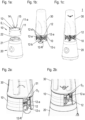
- FIG 1a a connector assembly 10 and a motor base 20 of a kitchen machine according to the present invention are shown in a perspective view, which kitchen machine in the present exemplary case is an electric blender.
- the connector assembly 10 comprises a housing 11 including first connection means 11-a for detachably fixing the connector assembly to a jug unit (not shown in Figure 1a ).
- the first connection means 11-a comprises a screw thread which is interrupted by slots S 1 extending parallel to a screwing axis of the thread.
- the slots S 1 serve to receive respective blocking members of a safety element further comprised by the connector assembly (and not shown in Figure 1a ) when the safety element is in its third position.
- the housing 11 of the connector assembly 10 further comprises second connection means configured to detachably couple the connector assembly 10 with the motor base 20.
- the second connection means is not visible therein Figure 1a , due to the perspective thereof.
- the second connection means is configured to interact with respective motor base connection means 21 which in this case are embodied as bayonet mount counter components of the motor base 20.
- the second connection means 11-b is seen to comprise a bayonet mount component.
- the connector assembly 10 depicted in Figures 1a, 1b further comprises a base surface 13 for a jug unit to be combined with the connector assembly 10, a tool holder 14 and a rotatable tool 15 which in the present case is a rotatable knife assembly.
- a clutch unit (not visible in Figure 1a ) of the connector assembly is to be coupled, by mounting the connector assembly on the motor base, with a clutch element 22 of the motor base.
- a clutch unit 17 is visible.
- the mounting (and therewith, coupling) of the connector assembly to the motor base is prevented when the jug is devoid of a jug unit. Thereby, a user is protected from being able to touch a driven tool.
- the protection is achieved, according to the present invention, by means of a safety element the connector assembly further comprises, which safety ring is hidden in the perspective of Figure 1a .
- the connector assembly 10 is shown when fixed to a jug unit 20.
- the safety element 12 inside the connector assembly 10 is indicated.
- the safety element 12 comprises a ring portion 12-R, several blocking members 12-a configured to interfere with the first connection means 11-a (comprising a thread) when the safety element is in its third position, and a plurality of blocking units 12-b configured to obstruct respective bayonet mount components when the safety element is in its first position.
- the jug unit 30 is coupled to the connector assembly 10, whereby the safety element 12 included in the connector assembly 10 is transferred from its first position to its second position, in which the first and the second connection means are unblocked (i.e., released).
- the safety element 12 may be rotated by the jug unit 30 when the jug unit is screwed in.
- the rotation may be caused by the jug unit 30 interacting with the blocking members 12-a when the jug unit is sufficiently screwed to the connector assembly 10.
- Stopper members 12-c of the safety element may serve to delimit the rotation by butting against respective limit stops 11-c in the housing 11 (such limit stops are seen in Figures 3a, 3b ). Thereby, precision in the transfer of safety element 12 to the second position may be ensured.
- Engaging elements 12-d comprised by the safety element are configured to engage with an elastic element 16 (further comprised by the connector assembly and not visible in Figures 1a - 1c , but referenced in Figure 3a ), so as to act thereon against an elastic force of the elastic element 16 when the safety element 12 is rotated by the jug unit.
- an elastic element 16 further comprised by the connector assembly and not visible in Figures 1a - 1c , but referenced in Figure 3a
- the safety element 12 is automatically rotated back from its second position to its first position.
- the connector assembly 10 is seen to be mounted, with the jug unit 30 being fixed thereto, to the motor base 20.
- the safety element is transferred, by the motor base 20, to a third position relative to the housing.
- the safety element 12 blocks the first connection means 11-a.
- the jug unit 30 can be detached from the connector assembly 10 being mounted on the motor base 20.
- a user is again protected from being able to touch a driven tool 15.
- the kitchen machine 1 is depicted in its designated orientation of utilisation.
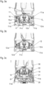
- FIGS 2a, 2b details of the protection mechanism according to the present invention are shown by means of an opening in the casing of the connector assembly 10.
- the opening allowing the insight in the interior of the connector assembly 10 is for illustration purposes.
- the connector assembly 10 is shown to be fixed to the jug unit 30.
- the safety element 12 is in its second position, in which the first and the second connection means are unblocked.
- the connector assembly 10 and the jug unit 20 can be rotated with respect to each other, as indicated by respective arrows, and the connector assembly can be mounted on a motor base (not shown in Figure 2a ).
- Figures 3a - 3c show details of the present invention in respective cross sections along a screwing axis of the first connection means 11-a (comprising a screw thread), which axis coincides with a rotation axis of a tool 15 comprised by the connector assembly 10.
- the safety element 12 is in its first position, in which position blocking units 12-b comprised by the safety element 12 obstruct bayonet mount components comprised by the second connection means 11-b.
- a connector assembly 10 for connecting a jug unit 30 with a motor base 20 of a kitchen machine 1.
- the connector assembly 10 comprises a housing 11, a movable safety element 12 and at least one elastic element 16.
- the safety element 12 In a first position relative to the housing 11, the safety element 12 unblocks first connection means 11-a for fixing the connector assembly to the jug unit, and blocks second connection means 11-b for mounting the connector element to a motor base.
- the safety element 12 unblocks both the first connection means 11-a and the second connection means 11-b.
- the safety element 12 can be transferred, against an elastic force of the elastic element 16, from its first to its second position by fixing the jug unit 30 to the connector assembly 10.
- a kitchen machine 1 comprising a connector assembly 10, a motor base 20 and a jug unit 30.
Landscapes
- Engineering & Computer Science (AREA)
- Mechanical Engineering (AREA)
- Food Science & Technology (AREA)
- Food-Manufacturing Devices (AREA)
- Apparatus For Making Beverages (AREA)
Claims (8)
- Verbinderanordnung (10) zum Verbinden einer Bechereinheit (30) mit einem Motorsockel (20) einer Küchenmaschine (1), wobei die Verbinderanordnung (10) Folgendes umfasst:- ein Gehäuse (11) mit ersten Verbindungsmitteln (11-a) zum lösbaren Fixieren der Verbinderanordnung an der Bechereinheit (30) und zweiten Verbindungsmitteln (11-b) zum lösbaren Ankoppeln der Verbinderanordnung (10) an den Motorsockel (20),- ein Sicherheitselement (12), das in Bezug auf das Gehäuse (11) beweglich ist, und- mindestens ein elastisches Element (16),wobei das Sicherheitselement (12) in einer ersten Position so angeordnet ist, dass es von der Bechereinheit (30), wenn diese an der Verbinderanordnung (10) fixiert ist, in eine zweite Position überführt wird, in der eine Federkraft des mindestens einen elastischen Elements (16) so ausgelegt ist, dass sie das Sicherheitselement (12) in dessen erste Position drückt,wobei das Sicherheitselement (12) so ausgelegt ist, dass es in seiner ersten Position das erste Verbindungsmittel (11-a) entsperrt und das zweite Verbindungsmittel (11-b) sperrt und in seiner zweiten Position sowohl das erste Verbindungsmittel (11-a) als auch das zweite Verbindungsmittel (11-b) entsperrt,dadurch gekennzeichnet, dass das Sicherheitselement (12) so angeordnet ist, dass es in seiner zweiten Position, wenn die Verbinderanordnung (10) an den Motorsockel gekoppelt wird, von dem Motorsockel (20) in eine dritte Position überführt wird, in der die Schwerkraft, die Federkraft des mindestens einen elastischen Elements (16) und/oder die Federkraft eines weiteren elastischen Elements so ausgelegt ist, dass sie das Sicherheitselement (12) in seine zweite Position drückt,wobei das Sicherheitselement (12) so ausgelegt ist, dass es in seiner dritten Position das erste Verbindungsmittel (11-a) sperrt und das zweite Verbindungsmittel (11-b) entsperrt.
- Verbinderanordnung (10) nach Anspruch 1, wobei das zweite Verbindungsmittel (11-b) ein Schraubgewinde und/oder eine Bajonettverschluss-Komponente umfasst.
- Verbinderanordnung (10) nach einem der vorhergehenden Ansprüche, wobei das erste Verbindungsmittel (11-a) ein Schraubgewinde und/oder eine Bajonettverschluss-Komponente umfasst.
- Verbinderanordnung (10) nach einem der vorhergehenden Ansprüche, die ferner eine Werkzeugaufnahme (14) umfasst, die so ausgelegt ist, dass sie ein Werkzeug (15) zum Verarbeiten von Lebensmitteln befestigt und einen Boden für die Bechereinheit (30) bereitstellt, wenn sie damit zusammengesetzt ist.
- Verbinderanordnung (10) nach einem der vorhergehenden Ansprüche, wobei das Sicherheitselement (12) einen Ringabschnitt (12-R) umfasst.
- Verbinderanordnung (10) nach Anspruch 5, wobei das Sicherheitselement (12) ferner eine oder mehrere Sperreinheiten (12-b) umfasst, die aus dem Ringabschnitt (12-R) in einer Richtung mit einer Komponente parallel zu einer Mittelachse des Ringabschnitts (12-R) vorstehen und so ausgelegt sind, dass sie das zweite Verbindungsmittel (11-b) behindern und/oder blockieren, wenn sich das Sicherheitselement (12) in seiner ersten Position befindet.
- Küchenmaschine (1) mit einer Bechereinheit (30), einem Motorsockel und einer Verbinderanordnung (10) nach einem der vorhergehenden Ansprüche, die so ausgelegt ist, dass sie die Bechereinheit (30) mit dem Motorsockel (20) verbindet.
- Küchenmaschine (1) nach Anspruch 7, wobei die Küchenmaschine einen elektrischen Mixer umfasst.
Priority Applications (3)
| Application Number | Priority Date | Filing Date | Title |
|---|---|---|---|
| EP20198974.6A EP3973833B1 (de) | 2020-09-29 | 2020-09-29 | Verbinderanordnung für eine küchenmaschine und küchenmaschine mit einer verbinderanordnung |
| EP20204618.1A EP3973830A1 (de) | 2020-09-29 | 2020-10-29 | Verbinderanordnung für eine küchenmaschine und küchenmaschine mit einer verbinderanordnung |
| CN202111143648.0A CN114305164A (zh) | 2020-09-29 | 2021-09-28 | 用于厨房机器的连接器组件和具有连接器组件的厨房机器 |
Applications Claiming Priority (1)
| Application Number | Priority Date | Filing Date | Title |
|---|---|---|---|
| EP20198974.6A EP3973833B1 (de) | 2020-09-29 | 2020-09-29 | Verbinderanordnung für eine küchenmaschine und küchenmaschine mit einer verbinderanordnung |
Publications (3)
| Publication Number | Publication Date |
|---|---|
| EP3973833A1 EP3973833A1 (de) | 2022-03-30 |
| EP3973833C0 EP3973833C0 (de) | 2024-12-04 |
| EP3973833B1 true EP3973833B1 (de) | 2024-12-04 |
Family
ID=72670581
Family Applications (2)
| Application Number | Title | Priority Date | Filing Date |
|---|---|---|---|
| EP20198974.6A Active EP3973833B1 (de) | 2020-09-29 | 2020-09-29 | Verbinderanordnung für eine küchenmaschine und küchenmaschine mit einer verbinderanordnung |
| EP20204618.1A Pending EP3973830A1 (de) | 2020-09-29 | 2020-10-29 | Verbinderanordnung für eine küchenmaschine und küchenmaschine mit einer verbinderanordnung |
Family Applications After (1)
| Application Number | Title | Priority Date | Filing Date |
|---|---|---|---|
| EP20204618.1A Pending EP3973830A1 (de) | 2020-09-29 | 2020-10-29 | Verbinderanordnung für eine küchenmaschine und küchenmaschine mit einer verbinderanordnung |
Country Status (2)
| Country | Link |
|---|---|
| EP (2) | EP3973833B1 (de) |
| CN (1) | CN114305164A (de) |
Families Citing this family (1)
| Publication number | Priority date | Publication date | Assignee | Title |
|---|---|---|---|---|
| USD988067S1 (en) | 2022-12-12 | 2023-06-06 | E. Mishan & Sons, Inc. | Blender |
Family Cites Families (10)
| Publication number | Priority date | Publication date | Assignee | Title |
|---|---|---|---|---|
| US3612126A (en) * | 1969-08-14 | 1971-10-12 | Dynamics Corp America | Liquidizer safety clutch |
| US3627008A (en) * | 1969-11-12 | 1971-12-14 | Dynamics Corp America | Safety blender jar |
| US3786999A (en) * | 1972-01-11 | 1974-01-22 | Ronson Corp | Safety mechanism to prevent shaft coupling when blades are exposed in a blender |
| US3785579A (en) * | 1972-03-27 | 1974-01-15 | Dynamics Corp America | Liquidizer safety clutch |
| EP1045658B1 (de) * | 1998-10-23 | 2003-11-26 | Koninklijke Philips Electronics N.V. | Zusatzgerät mit sicherheitsglied für küchenmaschinen |
| GB2414381A (en) * | 2004-05-29 | 2005-11-30 | Kenwood Marks Ltd | Safe kitchen appliance which only works when its container is correctly positioned |
| GB2417538B (en) * | 2004-08-26 | 2008-04-02 | Kenwood Marks Ltd | Safety system |
| US8240909B2 (en) * | 2009-07-17 | 2012-08-14 | Whirlpool Corporation | Blender jar interlock |
| US9775467B2 (en) * | 2013-10-07 | 2017-10-03 | Capbran Holdings, Llc | Blender |
| US10898028B2 (en) * | 2017-06-30 | 2021-01-26 | Capbran Holdings, Llc | Mixer with safety mechanisms |
-
2020
- 2020-09-29 EP EP20198974.6A patent/EP3973833B1/de active Active
- 2020-10-29 EP EP20204618.1A patent/EP3973830A1/de active Pending
-
2021
- 2021-09-28 CN CN202111143648.0A patent/CN114305164A/zh active Pending
Also Published As
| Publication number | Publication date |
|---|---|
| EP3973830A1 (de) | 2022-03-30 |
| EP3973833C0 (de) | 2024-12-04 |
| EP3973833A1 (de) | 2022-03-30 |
| CN114305164A (zh) | 2022-04-12 |
Similar Documents
| Publication | Publication Date | Title |
|---|---|---|
| RU2636561C2 (ru) | Система обеспечения безопасности для бытового устройства переработки пищевых продуктов | |
| US10799070B2 (en) | Mixing tool lock for a kitchen appliance | |
| EP3644813B1 (de) | Mischer mit sicherheitsmechanismen | |
| EP3973833B1 (de) | Verbinderanordnung für eine küchenmaschine und küchenmaschine mit einer verbinderanordnung | |
| CN109196745B (zh) | 带有分离开关的手持式工具机 | |
| US20130047762A1 (en) | Switchable gear drive for a handheld power tool | |
| JP6805331B2 (ja) | 工作機械、工作機械システム、及び、工作機械の利用法 | |
| EP1045658B1 (de) | Zusatzgerät mit sicherheitsglied für küchenmaschinen | |
| WO2013030710A1 (en) | A lid for a food processor | |
| WO2009106808A1 (en) | Kitchen machine | |
| CN105619150B (zh) | 制动机构及采用该制动机构的加工装置 | |
| JPS60207704A (ja) | 衝撃ドリル用のドリルチヤツク | |
| EP2915630A1 (de) | Radhalteflansch für Schleiftopfscheibenräder mit einem Schnellauslösesystem für das Rad | |
| SE442596B (sv) | Centrifugalseparator med radiella urtagningar for kapillerror | |
| KR20220119482A (ko) | 식품 가공기 및 이의 칼세트 장착구조와 믹싱컵 | |
| RU2578585C2 (ru) | Инструмент для приводимого двигателем кухонного прибора | |
| US12030167B2 (en) | False triggering prevention device for spindle self-locking mechanism of electric tool | |
| CN116507451A (zh) | 具有前手柄和调节单元的动力工具 | |
| CN102573587A (zh) | 旋转烹调装置 | |
| US20190022766A1 (en) | Electrical Handheld Core Drilling Device | |
| CN111997970B (zh) | 一种led显示屏背架 | |
| EP2524765A1 (de) | Schleifgerät | |
| JPH10109247A (ja) | 作業機器の回転軸承された工具のための回転防止装置 | |
| CN216797435U (zh) | 一种具备电刀功能的手持式搅拌机 | |
| JP4104879B2 (ja) | シュレッダー |
Legal Events
| Date | Code | Title | Description |
|---|---|---|---|
| PUAI | Public reference made under article 153(3) epc to a published international application that has entered the european phase |
Free format text: ORIGINAL CODE: 0009012 |
|
| STAA | Information on the status of an ep patent application or granted ep patent |
Free format text: STATUS: THE APPLICATION HAS BEEN PUBLISHED |
|
| AK | Designated contracting states |
Kind code of ref document: A1 Designated state(s): AL AT BE BG CH CY CZ DE DK EE ES FI FR GB GR HR HU IE IS IT LI LT LU LV MC MK MT NL NO PL PT RO RS SE SI SK SM TR |
|
| STAA | Information on the status of an ep patent application or granted ep patent |
Free format text: STATUS: REQUEST FOR EXAMINATION WAS MADE |
|
| 17P | Request for examination filed |
Effective date: 20220930 |
|
| RBV | Designated contracting states (corrected) |
Designated state(s): AL AT BE BG CH CY CZ DE DK EE ES FI FR GB GR HR HU IE IS IT LI LT LU LV MC MK MT NL NO PL PT RO RS SE SI SK SM TR |
|
| GRAP | Despatch of communication of intention to grant a patent |
Free format text: ORIGINAL CODE: EPIDOSNIGR1 |
|
| STAA | Information on the status of an ep patent application or granted ep patent |
Free format text: STATUS: GRANT OF PATENT IS INTENDED |
|
| INTG | Intention to grant announced |
Effective date: 20240719 |
|
| GRAS | Grant fee paid |
Free format text: ORIGINAL CODE: EPIDOSNIGR3 |
|
| GRAA | (expected) grant |
Free format text: ORIGINAL CODE: 0009210 |
|
| STAA | Information on the status of an ep patent application or granted ep patent |
Free format text: STATUS: THE PATENT HAS BEEN GRANTED |
|
| AK | Designated contracting states |
Kind code of ref document: B1 Designated state(s): AL AT BE BG CH CY CZ DE DK EE ES FI FR GB GR HR HU IE IS IT LI LT LU LV MC MK MT NL NO PL PT RO RS SE SI SK SM TR |
|
| REG | Reference to a national code |
Ref country code: CH Ref legal event code: EP |
|
| REG | Reference to a national code |
Ref country code: DE Ref legal event code: R096 Ref document number: 602020042392 Country of ref document: DE |
|
| REG | Reference to a national code |
Ref country code: IE Ref legal event code: FG4D |
|
| U01 | Request for unitary effect filed |
Effective date: 20241220 |
|
| U07 | Unitary effect registered |
Designated state(s): AT BE BG DE DK EE FI FR IT LT LU LV MT NL PT RO SE SI Effective date: 20250113 |
|
| PG25 | Lapsed in a contracting state [announced via postgrant information from national office to epo] |
Ref country code: HR Free format text: LAPSE BECAUSE OF FAILURE TO SUBMIT A TRANSLATION OF THE DESCRIPTION OR TO PAY THE FEE WITHIN THE PRESCRIBED TIME-LIMIT Effective date: 20241204 |
|
| PG25 | Lapsed in a contracting state [announced via postgrant information from national office to epo] |
Ref country code: ES Free format text: LAPSE BECAUSE OF FAILURE TO SUBMIT A TRANSLATION OF THE DESCRIPTION OR TO PAY THE FEE WITHIN THE PRESCRIBED TIME-LIMIT Effective date: 20241204 |
|
| PG25 | Lapsed in a contracting state [announced via postgrant information from national office to epo] |
Ref country code: NO Free format text: LAPSE BECAUSE OF FAILURE TO SUBMIT A TRANSLATION OF THE DESCRIPTION OR TO PAY THE FEE WITHIN THE PRESCRIBED TIME-LIMIT Effective date: 20250304 |
|
| PG25 | Lapsed in a contracting state [announced via postgrant information from national office to epo] |
Ref country code: GR Free format text: LAPSE BECAUSE OF FAILURE TO SUBMIT A TRANSLATION OF THE DESCRIPTION OR TO PAY THE FEE WITHIN THE PRESCRIBED TIME-LIMIT Effective date: 20250305 |
|
| PG25 | Lapsed in a contracting state [announced via postgrant information from national office to epo] |
Ref country code: RS Free format text: LAPSE BECAUSE OF FAILURE TO SUBMIT A TRANSLATION OF THE DESCRIPTION OR TO PAY THE FEE WITHIN THE PRESCRIBED TIME-LIMIT Effective date: 20250304 |
|
| PG25 | Lapsed in a contracting state [announced via postgrant information from national office to epo] |
Ref country code: SM Free format text: LAPSE BECAUSE OF FAILURE TO SUBMIT A TRANSLATION OF THE DESCRIPTION OR TO PAY THE FEE WITHIN THE PRESCRIBED TIME-LIMIT Effective date: 20241204 |
|
| PG25 | Lapsed in a contracting state [announced via postgrant information from national office to epo] |
Ref country code: PL Free format text: LAPSE BECAUSE OF FAILURE TO SUBMIT A TRANSLATION OF THE DESCRIPTION OR TO PAY THE FEE WITHIN THE PRESCRIBED TIME-LIMIT Effective date: 20241204 |
|
| PG25 | Lapsed in a contracting state [announced via postgrant information from national office to epo] |
Ref country code: IS Free format text: LAPSE BECAUSE OF FAILURE TO SUBMIT A TRANSLATION OF THE DESCRIPTION OR TO PAY THE FEE WITHIN THE PRESCRIBED TIME-LIMIT Effective date: 20250404 |
|
| PG25 | Lapsed in a contracting state [announced via postgrant information from national office to epo] |
Ref country code: SK Free format text: LAPSE BECAUSE OF FAILURE TO SUBMIT A TRANSLATION OF THE DESCRIPTION OR TO PAY THE FEE WITHIN THE PRESCRIBED TIME-LIMIT Effective date: 20241204 |
|
| PG25 | Lapsed in a contracting state [announced via postgrant information from national office to epo] |
Ref country code: CZ Free format text: LAPSE BECAUSE OF FAILURE TO SUBMIT A TRANSLATION OF THE DESCRIPTION OR TO PAY THE FEE WITHIN THE PRESCRIBED TIME-LIMIT Effective date: 20241204 |
|
| PLBE | No opposition filed within time limit |
Free format text: ORIGINAL CODE: 0009261 |
|
| STAA | Information on the status of an ep patent application or granted ep patent |
Free format text: STATUS: NO OPPOSITION FILED WITHIN TIME LIMIT |
|
| U20 | Renewal fee for the european patent with unitary effect paid |
Year of fee payment: 6 Effective date: 20250930 |
|
| 26N | No opposition filed |
Effective date: 20250905 |