EP3973756A1 - Gezogene landwirtschaftliche erntemaschnie mit einer verstellbaren achsvorrichtung - Google Patents
Gezogene landwirtschaftliche erntemaschnie mit einer verstellbaren achsvorrichtung Download PDFInfo
- Publication number
- EP3973756A1 EP3973756A1 EP21197028.0A EP21197028A EP3973756A1 EP 3973756 A1 EP3973756 A1 EP 3973756A1 EP 21197028 A EP21197028 A EP 21197028A EP 3973756 A1 EP3973756 A1 EP 3973756A1
- Authority
- EP
- European Patent Office
- Prior art keywords
- wheels
- frame
- machine
- processing unit
- agricultural machine
- Prior art date
- Legal status (The legal status is an assumption and is not a legal conclusion. Google has not performed a legal analysis and makes no representation as to the accuracy of the status listed.)
- Pending
Links
- 238000003306 harvesting Methods 0.000 title claims abstract description 10
- 238000000034 method Methods 0.000 claims description 11
- 238000005096 rolling process Methods 0.000 claims description 9
- 241000196324 Embryophyta Species 0.000 claims description 7
- 244000025254 Cannabis sativa Species 0.000 claims description 5
- 206010016322 Feeling abnormal Diseases 0.000 claims description 4
- 230000006378 damage Effects 0.000 description 4
- 208000027418 Wounds and injury Diseases 0.000 description 2
- 238000005452 bending Methods 0.000 description 2
- 238000005056 compaction Methods 0.000 description 2
- 238000010276 construction Methods 0.000 description 2
- 238000001035 drying Methods 0.000 description 2
- 230000005484 gravity Effects 0.000 description 2
- 208000014674 injury Diseases 0.000 description 2
- 238000000926 separation method Methods 0.000 description 2
- 241001080024 Telles Species 0.000 description 1
- 238000009825 accumulation Methods 0.000 description 1
- 230000002730 additional effect Effects 0.000 description 1
- 230000015572 biosynthetic process Effects 0.000 description 1
- 230000008878 coupling Effects 0.000 description 1
- 238000010168 coupling process Methods 0.000 description 1
- 238000005859 coupling reaction Methods 0.000 description 1
- 239000004459 forage Substances 0.000 description 1
- 238000012986 modification Methods 0.000 description 1
- 230000004048 modification Effects 0.000 description 1
- 210000000056 organ Anatomy 0.000 description 1
- 238000006467 substitution reaction Methods 0.000 description 1
- 235000013311 vegetables Nutrition 0.000 description 1
Images


Classifications
-
- A—HUMAN NECESSITIES
- A01—AGRICULTURE; FORESTRY; ANIMAL HUSBANDRY; HUNTING; TRAPPING; FISHING
- A01B—SOIL WORKING IN AGRICULTURE OR FORESTRY; PARTS, DETAILS, OR ACCESSORIES OF AGRICULTURAL MACHINES OR IMPLEMENTS, IN GENERAL
- A01B73/00—Means or arrangements to facilitate transportation of agricultural machines or implements, e.g. folding frames to reduce overall width
- A01B73/02—Folding frames
- A01B73/04—Folding frames foldable about a horizontal axis
- A01B73/044—Folding frames foldable about a horizontal axis the axis being oriented in a longitudinal direction
-
- A—HUMAN NECESSITIES
- A01—AGRICULTURE; FORESTRY; ANIMAL HUSBANDRY; HUNTING; TRAPPING; FISHING
- A01B—SOIL WORKING IN AGRICULTURE OR FORESTRY; PARTS, DETAILS, OR ACCESSORIES OF AGRICULTURAL MACHINES OR IMPLEMENTS, IN GENERAL
- A01B63/00—Lifting or adjusting devices or arrangements for agricultural machines or implements
- A01B63/14—Lifting or adjusting devices or arrangements for agricultural machines or implements for implements drawn by animals or tractors
- A01B63/16—Lifting or adjusting devices or arrangements for agricultural machines or implements for implements drawn by animals or tractors with wheels adjustable relatively to the frame
- A01B63/163—Lifting or adjusting devices or arrangements for agricultural machines or implements for implements drawn by animals or tractors with wheels adjustable relatively to the frame laterally adjustable
-
- B—PERFORMING OPERATIONS; TRANSPORTING
- B60—VEHICLES IN GENERAL
- B60B—VEHICLE WHEELS; CASTORS; AXLES FOR WHEELS OR CASTORS; INCREASING WHEEL ADHESION
- B60B27/00—Hubs
- B60B27/0047—Hubs characterised by functional integration of other elements
- B60B27/0052—Hubs characterised by functional integration of other elements the element being a brake disc
-
- B—PERFORMING OPERATIONS; TRANSPORTING
- B60—VEHICLES IN GENERAL
- B60B—VEHICLE WHEELS; CASTORS; AXLES FOR WHEELS OR CASTORS; INCREASING WHEEL ADHESION
- B60B35/00—Axle units; Parts thereof ; Arrangements for lubrication of axles
- B60B35/02—Dead axles, i.e. not transmitting torque
- B60B35/10—Dead axles, i.e. not transmitting torque adjustable for varying track
- B60B35/1036—Dead axles, i.e. not transmitting torque adjustable for varying track operated with power assistance
- B60B35/1054—Dead axles, i.e. not transmitting torque adjustable for varying track operated with power assistance hydraulically
-
- A—HUMAN NECESSITIES
- A01—AGRICULTURE; FORESTRY; ANIMAL HUSBANDRY; HUNTING; TRAPPING; FISHING
- A01B—SOIL WORKING IN AGRICULTURE OR FORESTRY; PARTS, DETAILS, OR ACCESSORIES OF AGRICULTURAL MACHINES OR IMPLEMENTS, IN GENERAL
- A01B73/00—Means or arrangements to facilitate transportation of agricultural machines or implements, e.g. folding frames to reduce overall width
- A01B73/005—Means or arrangements to facilitate transportation of agricultural machines or implements, e.g. folding frames to reduce overall width for endwise transportation, i.e. the direction of transport being substantially perpendicular to the direction of agricultural operation
-
- A—HUMAN NECESSITIES
- A01—AGRICULTURE; FORESTRY; ANIMAL HUSBANDRY; HUNTING; TRAPPING; FISHING
- A01D—HARVESTING; MOWING
- A01D57/00—Delivering mechanisms for harvesters or mowers
- A01D57/20—Delivering mechanisms for harvesters or mowers with conveyor belts
-
- B—PERFORMING OPERATIONS; TRANSPORTING
- B60—VEHICLES IN GENERAL
- B60B—VEHICLE WHEELS; CASTORS; AXLES FOR WHEELS OR CASTORS; INCREASING WHEEL ADHESION
- B60B2900/00—Purpose of invention
- B60B2900/30—Increase in
- B60B2900/351—Increase in versatility, e.g. usable for different purposes or different arrangements
-
- B—PERFORMING OPERATIONS; TRANSPORTING
- B60—VEHICLES IN GENERAL
- B60Y—INDEXING SCHEME RELATING TO ASPECTS CROSS-CUTTING VEHICLE TECHNOLOGY
- B60Y2200/00—Type of vehicle
- B60Y2200/20—Off-Road Vehicles
- B60Y2200/22—Agricultural vehicles
Definitions
- the present invention relates to the field of agricultural machinery, more particularly trailed agricultural harvesting machines, and relates to a two-unit trailed agricultural machine and its method of implementation.
- the invention relates to a trailed agricultural machine for harvesting a plant product such as grass, moving normally in a direction of advance A.
- Such a machine generally comprises a frame on which are mounted, on the one hand, an axle device connecting two wheels to the frame, and, on the other hand, two processing units each equipped with a respective grouping member.
- Each processing unit is articulated with the chassis at least around a folding axis so as to be able to selectively occupy at least: i) a working position in which it extends transversely to a direction of advance and rests at least partially on the ground, ii) a maneuvering position in which its weight is entirely supported by the frame and in which its outer end is farther from the frame than the outer end of each wheel, and iii) a transport position in which it extends transversely to the bearing axis of the respective wheel.
- a trailed agricultural machine comprising two processing units as described above is known from the document EP 2 042 023 A1 . Thanks to these two units, this machine has a large working width allowing the entire field to be harvested in fewer passes.
- the weight of the two units can lead, in particular on slopes and/or during tight turns, or on a bumpy road, tipping over the side of the machine. Such tipping causes the machine to be immobilized, and can cause damage to the machine and/or the tractor, as well as serious injury to people in the vicinity.
- the quantity of product moved by the machine is proportional to the working width.
- a large working width implies that the quantity of product moved by the machine is greater.
- the product is directed to the center of the machine by the grouping members, it is circumscribed by the wheels, the frame and/or the axle device.
- the volume of product can be such that the windrow becomes compacted, resulting in slower, more uneven drying and lower forage quality.
- the wheels also present a higher risk of rolling on the swath, which leads to even greater compaction of the product at the level of the treads.
- the main purpose of the present invention is to overcome the main drawbacks of the aforementioned known solution, namely to provide an agricultural machine, in particular but not limited to a swather-mower, which does not or less compacts the product, without compromising its stability, especially during maneuvers. Furthermore, this machine should preferably not have an increased width or length during transport.
- an important attribute of the invention consists in that, in an agricultural machine as presented in the introduction, the axle device is configured in such a way that the spacing between wheels is adjustable, at least between a constricted configuration and a configuration deviated from the latter.
- the figures 1 to 4 , 7 and 8 show an agricultural machine (1) for harvesting a vegetable product such as grass or the like.
- the machine (1) is moved in a feed direction (A).
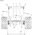
- This trailed machine (1) comprises a frame (2) on which is mounted an axle device (4) connecting two wheels (5, 5') to the frame (2).
- On the frame (2) are also mounted two processing units (20, 20') each equipped with a grouping member (14, 14').
- Each processing unit (20, 20') is articulated with the frame (2) at least around a folding axis (30, 30') so as to be able to selectively occupy one position among at least: a working position in which it extends transversely to the direction of advance (A) and rests at least partially on the ground (S), a maneuvering position in which its weight is entirely supported by the chassis (2) and in which its outer end (21, 21') is farther from the frame (2) than the outer end (27, 27') of each wheel (5, 5'), and a transport position in which it extends transversely to the rolling axis (AR, AR') of the wheel (5 , 5′) respectively.
- a processing unit (20, 20') extends in one direction means herein that its longitudinal or main dimension extends in said direction.
- the frame (2) respectively the machine (1), is traversed by a median plane (M) parallel to the direction of advance (A).
- the median plane (M) divides said machine (1) into two substantially identical halves and thus constitutes at least overall a plane of symmetry.
- the second processing unit (20') is located on the other side of the frame (2), respectively of the median plane (M), with respect to the first unit (20).
- the second processing unit (20') is substantially identical to the first processing unit (20). It is mounted on the chassis (2) symmetrically to the first processing unit (20) with respect to the median plane (M).
- the frame (2) respectively its longitudinal dimension, preferably extends parallel to the direction of advance (A).
- Each wheel (5, 5') is pivotable with respect to the frame (2) around its respective bearing axis (AR, AR').
- Each bending axis (30, 30') is transverse to the direction of advance (A), at least in the working position of the respective processing unit (20, 20').
- each bending axis (30, 30') is substantially parallel to the direction of advance (A) in the working position of the respective processing unit (20, 20').
- Each processing unit (20, 20') is equipped with a respective grouping member (14, 14').
- the grouping member (14, 14') is intended to move the product transversely to the direction of advance (A).
- Each grouping member (14, 14') is configured to deposit the product on the ground (S) in a windrow longitudinal to the direction of advance (A).
- the grouping members (14, 14') can deposit the product on the ground (S) between them, and preferably between the wheels (5, 5'). In this case, we speak of central removal.
- each processing unit (20, 20') occupies a working position in which it extends transversely, and preferably orthogonally, to the direction of advance (A) and rests at least partially on the ground (S).
- each processing unit (20, 20') occupies a maneuvering position in which it extends transversely to the direction of advance (A).
- the maneuvering position of the treatment units (20, 20') allows easy movement between two working phases without disturbing the surfaces already treated and being able to perform movements that are impossible in a working position of a unit (20, 20' ).
- the outer end (21, 21') of a processing unit (20, 20') is farther from the chassis (2), respectively from the median plane (M), than the outer end (27, 27') of each wheel (5, 5').
- the weight of each processing unit (20, 20') is entirely supported by the frame (2).
- the processing unit (20, 20') considered is not in contact with the ground (S).
- the outer end (21, 21') of a processing unit (20, 20') is preferably farther from the ground (S) than its inner end (22, 22'), increasing the risk of tipping.
- each processing unit (20, 20') occupies a transport position in which it extends transversely to the rolling axis (AR, AR') of the respective wheel (5, 5').
- the bearing axes (AR, AR') of the two wheels (5, 5') are orthogonal to the direction of advance (A).
- the bearing axles (AR, AR') preferably coincide.
- each processing unit (20, 20') preferably extends parallel to the direction of advance (A), at least when viewed from above.
- the machine (1) is characterized in that the axle device (4) is configured in such a way that the spacing (EV) between wheels (5, 5') is adjustable, at least between constricted and spread configurations.
- the wheels (5, 5') can thus selectively occupy at least one constricted configuration and one spaced-out configuration. In the spaced configuration, the spacing (EV) between wheels (5, 5') is greater than in the narrow configuration.
- the spacing (EV) between wheels (5, 5') is measured transversely to the direction of advance (A), and preferably parallel to the running axes (AR, AR') of the wheels (5, 5').
- the machine (1) After tilting, the machine (1) rests on one of the processing units (20, 20') thus damaging the plant cover of the ground (S). The tilting of the machine (1) therefore induces a slowing down of the agricultural site. It can also cause damage, particularly to the machine (1), or even injury.
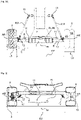
- the machine (1) comprises at least one link (8, 8') integrating a connecting rod (9, 9') articulated, on the one hand, with one or each wheel ( 5, 5') and, on the other hand, with the frame (2), the adjustment of the spacing (EV) between wheels (5, 5') being achieved by pivoting said link (8, 8').
- the axle device (4) comprises a fixed part (7) secured to the chassis (2), or integrated into the latter, and at least one movable part (6, 6 '), the adjustment of the spacing (EV) between wheels (5, 5') being achieved by sliding the or each movable part (6, 6') relative to the fixed part (7).
- the machine (1) comprises at least one pivoting link (8, 8') incorporating an articulated connecting rod (9, 9') and an axle device (4) with a fixed part (7) and at least one movable part (6, 6') mounted with the ability to slide with respect to said fixed part (7).
- This third variant thus combines the means of the aforementioned first and second variants.
- each wheel (5, 5') is integral with a movable part (6, 6') respectively of the axle device (4), which is connected in a sliding manner, along a longitudinal axis (AL, AL') corresponding transversely to the direction of advance (A), to a fixed part ( 7) of said axle device (4) integral with the frame (2), the spacing (EV) between the wheels (5, 5') being adjustable by sliding of at least one of the said movable parts (6, 6') with respect to said fixed part (7).
- This fixed part (7) can also constitute an element belonging to said frame (2).
- the wheels (5, 5') can in particular occupy a spaced configuration in the maneuvering position of at least one processing unit (20, 20'), advantageously making it possible to reduce the risk of the machine (1 ), in particular on slopes and/or during tight bends, thus improving the safety of use of the machine (1).
- the wheels (5, 5') advantageously also occupy the separated configuration in the working position of at least one processing unit (20, 20'), allowing the machine (1), respectively the grouping members (14, 14 '), to deposit a greater volume of product between the wheels (5, 5') while reducing the risk that the wheels (5, 5') roll over it.
- the product is therefore less compacted, which allows faster and more uniform drying.
- the quality of the fodder is thus improved.
- the product coming from one grouping member (14, 14') does not or less intertwine with that of the other (or other) grouping member(s) (14, 14'), this which promotes easy collection by a machine equipped with a collection device of the type known under the designation “pickup”.
- the wheels (5, 5') In the transport position of the processing units (20, 20'), the wheels (5, 5') occupy the constricted configuration so as to respect the standards of the Highway Code.
- the working width of the machine (1) and therefore its productivity are increased.
- the provision of an arrangement of the two processing units (20, 20') with, in the working position, an interval (I) of separation between the grouping members (14, 14'), further authorizes its use in a agricultural hitch also having a front processing unit (24).
- a hitch with a trailed machine (1) hitched to the rear of a tractor (T) to which a front treatment unit (24) is also hitched is illustrated in the figure 4 .
- the front processing unit (24) also comprises a central grouping member (25) arranged to deposit product between the wheels (5, 5') of the trailed machine (1).
- the spacing (EV) between the wheels (5, 5') is substantially equal to the width of the tractor (T).
- the machine (1) is designed to be dragged by the tractor (T) in the direction of advance (A).
- it is connected to the tractor (T) by a coupling device (3), preferably located at the front of the machine (1).
- each processing unit (20, 20') is located, seen in the direction of advance (A), in front of the wheels (5, 5').
- the processing units (20, 20') are located above the wheels (5, 5'), according to a side view.
- the wheels (5, 5') are also located on either side of the frame (2).
- the wheels (5, 5') are also located laterally beyond the frame (2), respectively at a distance on either side of the median plane (M).
- each of the wheels (5, 5') can be moved, along the respective rolling axis (AR, AR'), by a distance at least equal to half the width (L5, L5') of the respective wheel (5, 5'). More preferably, each wheel (5, 5') can be moved, along the respective bearing axis (AR, AR'), by a distance at least equal to three quarters of the respective width (L5, L5'), and more preferably still at least equal to the width (L5, L5') of the respective wheel (5, 5').
- the total width (LT) of the machine (1) is defined by the distance between the outer ends (21, 21') of the treatment units (20, 20 '). In the transport position, the total width (LT) of the machine (1) is advantageously at most equal to the distance base (LE) between the outer ends (27, 27 ') of the wheels (5, 5').
- the total width (LT) of the machine (1) is orthogonal to the direction of advance (A).
- each rolling axis (AR, AR') of the wheels (5, 5') is parallel to the total width (LT) of the machine (1).
- the total width (LT) of the machine (1) is greater than 8 meters, preferably greater than 10 meters, and more preferably still greater than 12 meters.
- the distance separating the outer ends (27, 27') of the wheels (5, 5') is called the base distance (LE).
- the distance base (LE) is greater than one-fifth of the total width (LT) of the machine (1).
- the base distance (LE) is greater than a third of the total width (LT), and more preferably still greater than a quarter of the total width (LT) of the machinery (1).
- the base distance (LE) the less the risk of the machine (1) tip.
- the base distance (LE) the base distance (LE) separating the outer ends (27, 27') of the wheels (5, 5 ') is greater than 3 meters, preferably greater than 3.5 meters, and more preferably still greater than 4 meters.
- the base distance (LE) separating the outer ends (27, 27') of the wheels (5, 5') is greater than 3 meters.
- each wheel (5, 5') has a respective width (L5, L5').
- the widths (L5, L5') of the wheels (5, 5') are equal.
- Each wheel (5, 5') can be made in one piece or be formed by the association of several rollers (60) of equal diameters and assembled together. In this case, it is considered that the width (L5, L5') of a wheel (5, 5') is the accumulation of the widths of the various rollers (60) which constitute it.
- the width (L5, L5') of each wheel (5, 5') is related to the weight of the processing units (20, 20').
- a minimum width (L5, L5') is necessary so as not to exert excessive pressure on the ground (S), thus avoiding compacting the ground (S) and/or damaging the plant cover.
- the base distance (LE) is equal to the sum of the spacing (EV) between wheels (5, 5'), the width (L5) of the first wheel (5) and the width ( L5') of the second wheel (5').
- the base distance (LE) is less than 4 meters, more preferably less than 3.5 meters, and more preferably still less than 3 meters.
- the passage from the tight configuration to the spaced-out configuration involves an advancement of the or each axis of rotation of the wheels (5, 5') with respect to the corresponding longitudinal axis (AL, AL'). Due to the link(s) (8, 8') between the mobile part(s) (6, 6') and the fixed part (7), this passage from the constricted configuration to the separated configuration also involves a lowering of the or each longitudinal axis (AL, AL'). It is apparent from the foregoing that the frame (2) is lower in the extended configuration than in the constricted configuration. The machine (1) thus has even more stability in the extended configuration. In the maneuvering position, the spacing (EV) between wheels (5, 5') being adjusted to the separated configuration, the center of gravity of the machine (1) is lower in maneuvering position than in transport position. The machine (1) is thus all the more stable in the operating position.
- the spacing (EV) between wheels (5, 5') is greater than one sixth of the total width (LT) of the machine (1).
- the spacing (EV) between wheels (5, 5') is greater than a quarter of the total width (LT), and more preferably still greater than a third of the width total (LT) of the machine (1).
- the spacing (EV) between wheels (5, 5') is substantially equal to the distance between the wheels of the tractor (T).
- the machine (1) comprises at least one adjustment control actuator (11, 11'), configured to adjust the spacing (EV) between the two wheels (5, 5').
- the or each adjustment actuator (11, 11') influences the base distance (LE) separating the outer ends (or faces) (27, 27') of said wheels (5, 5').
- the or each adjustment actuator (11, 11') is produced by at least one cylinder, preferably translating and hydraulic. In order to avoid damaging the plant cover, the or each adjustment actuator (11, 11') is actuated when the machine (1) advances. Also, the or each adjustment actuator (11, 11') can preferably be controlled from the tractor (T).
- a single adjustment actuator (11) is secured to each of the wheels (5, 5'), respectively connecting the two moving parts (6, 6').
- the machine (1) comprises two adjustment actuators (11, 11'). Each of the adjustment actuators (11, 11') is secured with the corresponding mobile part (6, 6') on the one hand, and with the frame (2), respectively the fixed part (7), on the other hand.
- the interval (I) is the distance separating the two grouping members (14, 14').
- the machine (1) comprises at least one actuator (23, 23') for controlling the adjustment of the interval (I) between the two grouping members (14, 14').
- each processing unit (20, 20') comprises its own transverse actuator (23, 23').
- the adjustment of the interval (I) between the grouping members (14, 14') is preferably carried out independently of the adjustment of the spacing (EV) between wheels (5, 5').
- the adjustment of the separation interval (I) between the grouping members (14, 14') can vary between 2 and 4 meters.
- the machine (1) can comprise two deflecting plates (26, 26') integral with the frame (2), making it possible to further avoid the entanglement of the windrows.
- Each is preferably associated with the grouping member (14, 14') of a processing unit (20, 20').
- Each deflector plate (26, 26') extends substantially orthogonally to the ground (S).
- Each deflector plate (26, 26') is oriented in the direction of advance (A).
- the rear end (28, 28') of each deflector plate (26, 26') is farther from the median plane (M) than the front end of the deflector plate (26, 26') concerned, in top view.
- Each deflector plate (26, 26') thus preferably forms an angle with the median plane (M) of between 10° and 30°.
- the rear end (28, 28') of each deflector plate (26, 26') is located between the inner end of the respective grouping member (14, 14') and the median plane (M), in view from above and in the working position of the processing unit (20, 20') concerned.
- Such an orientation allows the deflecting plates (26, 26') to deposit the product on either side of the product deposited by the central grouping member (25) of the front machine (24) and thus avoiding interference between the various swaths, the aforementioned plates contribute to the formation of a wider and more airy swath.
- Each processing unit (20, 20') is also equipped with a respective harvesting member (16, 16') located in front of the associated grouping member (14, 14'), at least in the working position of the processing unit (20, 20') considered.
- each harvesting member (16, 16') is a mowing member intended to mow the standing product.
- each processing unit (20, 20') can be equipped with a roller provided with fingers on the periphery, such as for example a conditioner mounted between the mowing member and the grouping member (14, 14' ).
- the roller is a means for picking up the product on the ground (S) arranged in front of the associated grouping member (14, 14').
- the axle device (4) connecting the two wheels (5, 5') to the chassis (2) is a telescopic axle.
- each wheel (5, 5') is secured to a movable part (6, 6') which is connected in a sliding manner along a respective longitudinal axis (AL, AL') transverse to the direction of advance (A) , to a fixed part (7) secured to the frame (2).
- each wheel (5, 5') is secured to the corresponding moving part (6, 6') by means of a hub (10,10') with a bearing axis (AR, AR') corresponding.
- the spacing (EV) between wheels (5, 5') is adjustable by sliding, relative to the fixed part (7), of at least one movable part (6, 6'), and preferably of both, according to the associated longitudinal axis (AL, AL').
- the longitudinal axes (AL, AL') are located above the axes (AR, AR') of hubs (10,10') so as to increase the surface delimited by the ground (S), the wheels (5, 5') and the axle device (4), making it possible to reduce the compaction of the product deposited on the ground (S).
- the longitudinal axes (AL, AL') of the movable parts (6, 6') are mutually aligned.
- the longitudinal axes (AL, AL') are, in the preferred embodiment, parallel to the running axes (AR, AR') of the wheels (5, 5').
- axle device (4) simple and resistant to stresses, makes it possible to maintain a reasonable diameter and width of the wheels (5, 5') while allowing a more voluminous deposit of product, but without being compacted or compacted.
- each movable part (6, 6'), with its corresponding longitudinal axis (AL, AL'), is also mechanically connected to the frame (2) by a respective link (8, 8'), each of said links (8, 8') being articulated, on the one hand, with the movable part (6, 6') by a first articulation (12, 12') and, on the other hand, with the frame (2) by a second articulation (13, 13').
- the or each link (8, 8') comprises an actuator, for example of the hydraulic cylinder type, in addition to the adjustment actuator (11, 11'), and which is configured to pivot the corresponding movable part (6, 6') about the corresponding longitudinal axis (AL, AL'), so as to advance the respective rolling axis (AR, AR') and/or so as to cause the respective longitudinal axis (AL, AL') to descend.
- an actuator for example of the hydraulic cylinder type, in addition to the adjustment actuator (11, 11')
- the or each link (8, 8') comprises an actuator, for example of the hydraulic cylinder type, in addition to the adjustment actuator (11, 11'), and which is configured to pivot the corresponding movable part (6, 6') about the corresponding longitudinal axis (AL, AL'), so as to advance the respective rolling axis (AR, AR') and/or so as to cause the respective longitudinal axis (AL, AL') to descend.
- Each link (8, 8') being integral with the corresponding mobile part (6, 6'), it is noted that, in an alternative embodiment represented on the figure 8 , the or each adjustment actuator (11, 11') can also, on the one hand, be articulated with the link (8, 8') so as to be secured with the wheel (5, 5'), and be secured with the frame (2) on the other hand.
- the two wheels (5, 5') are separated simultaneously and symmetrically (with the same amplitude) as soon as a processing unit (20, 20') passes from the transport position to another position (maneuvering or working).
- the passage from the transport position to one of the operating and working positions of each processing unit (20, 20') can be detected by a position sensor of the or each actuator (11, 11') of adjustment, or even by a position sensor between each processing unit (20, 20') and the frame (2).
- the frame (2) comprises a rocker (32) articulated with a central beam (33) around an elevation axis (34).
- the elevation axis (34) is parallel to the bearing axes (AR, AR') of the wheels (5, 5').
- the central beam (33) thus forms part of the frame (2).
- Each processing unit (20, 20') is articulated to the rocker (32) around a respective folding axis (30, 30').
- the rocker (32) In the transport position, the rocker (32) is oriented vertically.
- the folding axes (30, 30') are also oriented vertically in the transport position of the processing units (20, 20').
- the rocker (32) is pivoted with respect to the central beam (33) from a vertical position to a horizontal position about the elevation axis (34).
- a folding actuator (31, 31') is associated with each processing unit (20, 20') and is configured to make it pivot around the respective folding axis (30, 30').
- the folding actuator (31, 31') thus makes it possible to transpose a processing unit (20, 20') at least between working position and maneuvering position.
- the or each folding actuator (31, 31') is configured to allow each processing unit (20, 20') to pivot relative to the frame (2) around the folding axis (30, 30') respectively, depending on the unevenness of the ground (S).
- Each folding actuator (31, 31') is fixed, on the one hand, to the corresponding processing unit (20, 20'), and on the other hand to the frame (2), respectively to the rocker (32 ).
- the same wheel (5 or 5') can be moved away from the frame (2) regardless of the processing unit (20, 20') in the maneuvering or working position.
- the wheel (5, 5') closest to the unit in maneuvering position is moved away from the plane median (M).
- each of the wheels (5, 5') is at the same distance from the frame (2) in a configuration separated from the wheels (5 , 5').
- each of the wheels (5, 5') is at the same distance from the median plane (M).
- the invention also relates to a method for implementing a trailed agricultural machine (1) for harvesting a plant product such as grass, said machine comprising a frame (2) on which are mounted a device axle (4) connecting two wheels (5, 5') to the frame (2), and two processing units (20, 20') equipped with a respective grouping member (14, 14').
- Each processing unit (20, 20') is articulated with the frame (2) at least around a folding axis (30, 30') so as to be able to selectively occupy at least: a working position in which it extends transversely to a direction of advance (A) and rests at least partially on the ground (S), a maneuvering position in which its weight is entirely supported by the frame (2) and in which its outer end (21, 21') is farther from the chassis (2) than the outer end (27, 27') of each wheel (5, 5'), and a transport position in which it extends substantially transversely to the rolling axis (AR, AR') of the respective wheel (5, 5').
- Said method consists, as soon as at least one processing unit (20, 20') is transposed into the maneuvering position, in moving the wheels (5, 5') away from each other, in particular by causing them to pass from from a constricted configuration to a spread configuration.
- the spacing (EV) between wheels (5, 5') is adjusted in the configuration separated from the wheels (5, 5'), possibly automatically.
- a passage between the constricted and separated configurations, automatically controlled when at least one processing unit (20, 20') is transposed into the maneuvering position, has the advantage of ensuring the safety of use of the machine (1) if the driver were to forget to adjust the spacing (EV) of the wheels (5, 5') and makes it possible to avoid additional action.
- the method of operating the machine (1) also consists in automatically adjusting the spacing (EV) between wheels (5, 5') in the separated configuration, as soon as at least one processing unit (20, 20') is transferred to the working position.
- the method of operating the machine (1) also consists in automatically adjusting the spacing (EV) between wheels (5, 5') in configuration discarded, as soon as the two processing units (20, 20') are in the working or maneuvering position.
- the method of implementing the machine (1) also consists in automatically adjusting the spacing (EV) between wheels (5, 5') in a tight configuration, as soon as the two processing units (20, 20') are in transport position.
- a passage between the spaced configuration to the constricted configuration, and more generally an (automatic) adjustment in constricted configuration, is automatically controlled when the two processing units (20, 20') are in the transport position, has the advantage of ensure that the machine (1) has a reduced width ensuring the safety of use of the machine (1) if the driver were to forget to adjust the spacing (EV) of the wheels (5, 5 '), and also allows avoid further action.
Applications Claiming Priority (1)
| Application Number | Priority Date | Filing Date | Title |
|---|---|---|---|
| FR2009865A FR3114479B1 (fr) | 2020-09-29 | 2020-09-29 | Machine agricole trainée de récolte avec un essieu réglable |
Publications (1)
| Publication Number | Publication Date |
|---|---|
| EP3973756A1 true EP3973756A1 (de) | 2022-03-30 |
Family
ID=73498032
Family Applications (1)
| Application Number | Title | Priority Date | Filing Date |
|---|---|---|---|
| EP21197028.0A Pending EP3973756A1 (de) | 2020-09-29 | 2021-09-16 | Gezogene landwirtschaftliche erntemaschnie mit einer verstellbaren achsvorrichtung |
Country Status (2)
| Country | Link |
|---|---|
| EP (1) | EP3973756A1 (de) |
| FR (1) | FR3114479B1 (de) |
Citations (6)
| Publication number | Priority date | Publication date | Assignee | Title |
|---|---|---|---|---|
| FR2009860A1 (fr) | 1968-05-07 | 1970-02-13 | Nat Res Dev | Procede et appareil pour classer des fibres suivant leurs longueurs |
| DE4407695A1 (de) * | 1994-03-08 | 1995-09-14 | Karl Heitzler | Anhängerlafette |
| US5464243A (en) * | 1995-01-13 | 1995-11-07 | Deere & Company | Adjustable axle with shim structure |
| EP2042023A1 (de) | 2007-09-28 | 2009-04-01 | JF-Fabriken - J. Freudendahl A/S | Mäher mit Förderband |
| EP2168786A2 (de) * | 2008-09-24 | 2010-03-31 | Deere & Company | Transportpositionierungsstruktur und Verfahren für Lenkachsen |
| EP3707983A1 (de) * | 2019-03-13 | 2020-09-16 | Kuhn SAS | Landwirtschaftliche maschine mit einer verteilenden zugstange |
-
2020
- 2020-09-29 FR FR2009865A patent/FR3114479B1/fr active Active
-
2021
- 2021-09-16 EP EP21197028.0A patent/EP3973756A1/de active Pending
Patent Citations (6)
| Publication number | Priority date | Publication date | Assignee | Title |
|---|---|---|---|---|
| FR2009860A1 (fr) | 1968-05-07 | 1970-02-13 | Nat Res Dev | Procede et appareil pour classer des fibres suivant leurs longueurs |
| DE4407695A1 (de) * | 1994-03-08 | 1995-09-14 | Karl Heitzler | Anhängerlafette |
| US5464243A (en) * | 1995-01-13 | 1995-11-07 | Deere & Company | Adjustable axle with shim structure |
| EP2042023A1 (de) | 2007-09-28 | 2009-04-01 | JF-Fabriken - J. Freudendahl A/S | Mäher mit Förderband |
| EP2168786A2 (de) * | 2008-09-24 | 2010-03-31 | Deere & Company | Transportpositionierungsstruktur und Verfahren für Lenkachsen |
| EP3707983A1 (de) * | 2019-03-13 | 2020-09-16 | Kuhn SAS | Landwirtschaftliche maschine mit einer verteilenden zugstange |
Also Published As
| Publication number | Publication date |
|---|---|
| FR3114479B1 (fr) | 2023-01-13 |
| FR3114479A1 (fr) | 2022-04-01 |
Similar Documents
| Publication | Publication Date | Title |
|---|---|---|
| EP0429381B1 (de) | Landmaschine mit verbesserter Aufhängungsvorrichtung der Arbeitswerkzeugeeinheit | |
| EP1366650B1 (de) | Landwirschaftliche Maschine mit einer Vorrichtung für die Transportstellung | |
| EP1684569B1 (de) | Landmaschine zum schwaden von auf dem boden liegenden produkten | |
| EP2699074B1 (de) | Landwirtschaftliche maschine mit verbesserter faltvorrichtung | |
| FR2746576A1 (fr) | Machine agricole du genre faneuse a rateaux rotatifs multiples, convertible d'une position de travail deployee a une position de transport ramassee | |
| EP1142468B1 (de) | Heuwerbungsmaschine | |
| EP0517632A1 (de) | Landmaschine, insbesondere ein Pflanzenschwader | |
| EP0514302B1 (de) | Verbesserter Pflanzenschwader | |
| FR2664127A1 (fr) | Machine agricole, notamment une andaineuse de vegetaux, a largeur de travail reglable. | |
| EP3973756A1 (de) | Gezogene landwirtschaftliche erntemaschnie mit einer verstellbaren achsvorrichtung | |
| EP3973757A1 (de) | Gezogene oder aufgesattelte landwirtschaftliche maschine mit einer verstellbaren achsvorrichtung | |
| EP0857413B1 (de) | Heuwerbungsmaschine | |
| EP1926363A2 (de) | Heuerntemaschine mit faltbaren seitlichen strukturen | |
| EP1111986B1 (de) | Fahrwerk für landwirtschaftliche maschine | |
| EP1670306B1 (de) | Heuerntemaschine mit einer transportaufhängungsvorrichtung | |
| EP0914766B1 (de) | Heuwerbungsmachine | |
| EP4272538A1 (de) | Gesicherte heuwerbungsmaschine und methode dazu | |
| FR2722942A1 (fr) | Machine de fenaison comprenant une roue de ratissage pouvant etre pivote lateralement dans plusieurs positions de travail | |
| FR2798817A1 (fr) | Machine de fenaison, notamment une andaineuse avec plusieurs rotors s'appuyant sur le sol au moyen de roues porteuses | |
| FR2882621A1 (fr) | Andaineuse reversible | |
| EP0998843A1 (de) | Heumaschine | |
| FR2699044A1 (fr) | Machine de fenaison avec des roues de transport déplaçables en hauteur. |
Legal Events
| Date | Code | Title | Description |
|---|---|---|---|
| PUAI | Public reference made under article 153(3) epc to a published international application that has entered the european phase |
Free format text: ORIGINAL CODE: 0009012 |
|
| STAA | Information on the status of an ep patent application or granted ep patent |
Free format text: STATUS: THE APPLICATION HAS BEEN PUBLISHED |
|
| AK | Designated contracting states |
Kind code of ref document: A1 Designated state(s): AL AT BE BG CH CY CZ DE DK EE ES FI FR GB GR HR HU IE IS IT LI LT LU LV MC MK MT NL NO PL PT RO RS SE SI SK SM TR |
|
| STAA | Information on the status of an ep patent application or granted ep patent |
Free format text: STATUS: REQUEST FOR EXAMINATION WAS MADE |
|
| 17P | Request for examination filed |
Effective date: 20220927 |
|
| RBV | Designated contracting states (corrected) |
Designated state(s): AL AT BE BG CH CY CZ DE DK EE ES FI FR GB GR HR HU IE IS IT LI LT LU LV MC MK MT NL NO PL PT RO RS SE SI SK SM TR |
|
| P01 | Opt-out of the competence of the unified patent court (upc) registered |
Effective date: 20230622 |
|
| GRAP | Despatch of communication of intention to grant a patent |
Free format text: ORIGINAL CODE: EPIDOSNIGR1 |
|
| STAA | Information on the status of an ep patent application or granted ep patent |
Free format text: STATUS: GRANT OF PATENT IS INTENDED |
|
| RIC1 | Information provided on ipc code assigned before grant |
Ipc: A01D 57/20 20060101ALN20240206BHEP Ipc: A01B 73/00 20060101ALN20240206BHEP Ipc: B60B 35/10 20060101ALI20240206BHEP Ipc: B60B 27/00 20060101ALI20240206BHEP Ipc: A01B 73/04 20060101ALI20240206BHEP Ipc: A01B 63/16 20060101AFI20240206BHEP |
|
| INTG | Intention to grant announced |
Effective date: 20240227 |