EP3973554B1 - Schnelladevorrichtung für ein elektro- oder hybridfahrzeug - Google Patents
Schnelladevorrichtung für ein elektro- oder hybridfahrzeug Download PDFInfo
- Publication number
- EP3973554B1 EP3973554B1 EP20726171.0A EP20726171A EP3973554B1 EP 3973554 B1 EP3973554 B1 EP 3973554B1 EP 20726171 A EP20726171 A EP 20726171A EP 3973554 B1 EP3973554 B1 EP 3973554B1
- Authority
- EP
- European Patent Office
- Prior art keywords
- sheath
- charging
- charging device
- cables
- insulating layer
- Prior art date
- Legal status (The legal status is an assumption and is not a legal conclusion. Google has not performed a legal analysis and makes no representation as to the accuracy of the status listed.)
- Active
Links
Images
Classifications
-
- B—PERFORMING OPERATIONS; TRANSPORTING
- B60—VEHICLES IN GENERAL
- B60L—PROPULSION OF ELECTRICALLY-PROPELLED VEHICLES; SUPPLYING ELECTRIC POWER FOR AUXILIARY EQUIPMENT OF ELECTRICALLY-PROPELLED VEHICLES; ELECTRODYNAMIC BRAKE SYSTEMS FOR VEHICLES IN GENERAL; MAGNETIC SUSPENSION OR LEVITATION FOR VEHICLES; MONITORING OPERATING VARIABLES OF ELECTRICALLY-PROPELLED VEHICLES; ELECTRIC SAFETY DEVICES FOR ELECTRICALLY-PROPELLED VEHICLES
- B60L53/00—Methods of charging batteries, specially adapted for electric vehicles; Charging stations or on-board charging equipment therefor; Exchange of energy storage elements in electric vehicles
- B60L53/10—Methods of charging batteries, specially adapted for electric vehicles; Charging stations or on-board charging equipment therefor; Exchange of energy storage elements in electric vehicles characterised by the energy transfer between the charging station and the vehicle
- B60L53/11—DC charging controlled by the charging station, e.g. mode 4
-
- B—PERFORMING OPERATIONS; TRANSPORTING
- B60—VEHICLES IN GENERAL
- B60L—PROPULSION OF ELECTRICALLY-PROPELLED VEHICLES; SUPPLYING ELECTRIC POWER FOR AUXILIARY EQUIPMENT OF ELECTRICALLY-PROPELLED VEHICLES; ELECTRODYNAMIC BRAKE SYSTEMS FOR VEHICLES IN GENERAL; MAGNETIC SUSPENSION OR LEVITATION FOR VEHICLES; MONITORING OPERATING VARIABLES OF ELECTRICALLY-PROPELLED VEHICLES; ELECTRIC SAFETY DEVICES FOR ELECTRICALLY-PROPELLED VEHICLES
- B60L53/00—Methods of charging batteries, specially adapted for electric vehicles; Charging stations or on-board charging equipment therefor; Exchange of energy storage elements in electric vehicles
- B60L53/10—Methods of charging batteries, specially adapted for electric vehicles; Charging stations or on-board charging equipment therefor; Exchange of energy storage elements in electric vehicles characterised by the energy transfer between the charging station and the vehicle
- B60L53/14—Conductive energy transfer
- B60L53/18—Cables specially adapted for charging electric vehicles
-
- H—ELECTRICITY
- H01—ELECTRIC ELEMENTS
- H01B—CABLES; CONDUCTORS; INSULATORS; SELECTION OF MATERIALS FOR THEIR CONDUCTIVE, INSULATING OR DIELECTRIC PROPERTIES
- H01B7/00—Insulated conductors or cables characterised by their form
- H01B7/42—Insulated conductors or cables characterised by their form with arrangements for heat dissipation or conduction
- H01B7/421—Insulated conductors or cables characterised by their form with arrangements for heat dissipation or conduction for heat dissipation
-
- H—ELECTRICITY
- H01—ELECTRIC ELEMENTS
- H01B—CABLES; CONDUCTORS; INSULATORS; SELECTION OF MATERIALS FOR THEIR CONDUCTIVE, INSULATING OR DIELECTRIC PROPERTIES
- H01B7/00—Insulated conductors or cables characterised by their form
- H01B7/17—Protection against damage caused by external factors, e.g. sheaths or armouring
- H01B7/18—Protection against damage caused by wear, mechanical force or pressure; Sheaths; Armouring
- H01B7/1875—Multi-layer sheaths
-
- Y—GENERAL TAGGING OF NEW TECHNOLOGICAL DEVELOPMENTS; GENERAL TAGGING OF CROSS-SECTIONAL TECHNOLOGIES SPANNING OVER SEVERAL SECTIONS OF THE IPC; TECHNICAL SUBJECTS COVERED BY FORMER USPC CROSS-REFERENCE ART COLLECTIONS [XRACs] AND DIGESTS
- Y02—TECHNOLOGIES OR APPLICATIONS FOR MITIGATION OR ADAPTATION AGAINST CLIMATE CHANGE
- Y02T—CLIMATE CHANGE MITIGATION TECHNOLOGIES RELATED TO TRANSPORTATION
- Y02T10/00—Road transport of goods or passengers
- Y02T10/60—Other road transportation technologies with climate change mitigation effect
- Y02T10/70—Energy storage systems for electromobility, e.g. batteries
-
- Y—GENERAL TAGGING OF NEW TECHNOLOGICAL DEVELOPMENTS; GENERAL TAGGING OF CROSS-SECTIONAL TECHNOLOGIES SPANNING OVER SEVERAL SECTIONS OF THE IPC; TECHNICAL SUBJECTS COVERED BY FORMER USPC CROSS-REFERENCE ART COLLECTIONS [XRACs] AND DIGESTS
- Y02—TECHNOLOGIES OR APPLICATIONS FOR MITIGATION OR ADAPTATION AGAINST CLIMATE CHANGE
- Y02T—CLIMATE CHANGE MITIGATION TECHNOLOGIES RELATED TO TRANSPORTATION
- Y02T10/00—Road transport of goods or passengers
- Y02T10/60—Other road transportation technologies with climate change mitigation effect
- Y02T10/7072—Electromobility specific charging systems or methods for batteries, ultracapacitors, supercapacitors or double-layer capacitors
-
- Y—GENERAL TAGGING OF NEW TECHNOLOGICAL DEVELOPMENTS; GENERAL TAGGING OF CROSS-SECTIONAL TECHNOLOGIES SPANNING OVER SEVERAL SECTIONS OF THE IPC; TECHNICAL SUBJECTS COVERED BY FORMER USPC CROSS-REFERENCE ART COLLECTIONS [XRACs] AND DIGESTS
- Y02—TECHNOLOGIES OR APPLICATIONS FOR MITIGATION OR ADAPTATION AGAINST CLIMATE CHANGE
- Y02T—CLIMATE CHANGE MITIGATION TECHNOLOGIES RELATED TO TRANSPORTATION
- Y02T90/00—Enabling technologies or technologies with a potential or indirect contribution to GHG emissions mitigation
- Y02T90/10—Technologies relating to charging of electric vehicles
- Y02T90/14—Plug-in electric vehicles
Definitions
- the invention relates to the field of electric or hybrid vehicles. And it relates more particularly to the rapid charging of such vehicles.
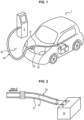
- the electric battery 10 of the vehicle is connected to the electrical network 2 by a charging assembly comprising on either side of a connector 50 two cables 31, 32, 31', 32'.
- the connector 50 makes it possible to connect or disconnect the charging device from the vehicle.
- the vehicle is charged using either alternating current or direct current, the vehicles being equipped to be charged using one or the other of the current types.
- two cables 31, 32 are connected on the one hand to the terminals of the battery 10 of the vehicle (a cable 31 for the positive terminal of the battery and a cable 32 for the negative terminal of the battery) and on the other hand to the connector 50.
- the part between the connector 50 and the battery is therefore located inside the vehicle 1.
- two cables 31', 32' are connected on the one hand to the connector 50 and on the other hand to the electrical network 2.
- the part between the connector 50 and the electrical network 2 is therefore located outside the vehicle 1.
- the two cables 31', 32' are preferably arranged within the same envelope to form a power cable 40.
- each charging cable 31, 32 is separately insulated and protected together with one or more braids 30, of textile or metallic nature.
- each charging cable 31, 32 comprises an electrical conductor 8 surrounded by an insulating layer 9.
- the outer part and the inner part constitute a charging assembly, the inner part constitutes an internal charging device.
- the connector is sized for long-term charging, and we want to use it in a short-term application.
- this results in a significant increase in temperature on this connector during fast charging.
- the invention proposes to overcome the aforementioned drawback.
- the invention proposes, according to a first aspect, a charging device for a hybrid or electric vehicle intended to be connected to an electricity distribution network, on the one hand, and to the terminals of a battery of a hybrid or electric vehicle on the other hand, said device comprising two charging cables, each being intended to be connected to a terminal of the battery, each charging cable comprising an electrical conductor and at least one insulating layer surrounding the electrical conductor, each charging cable further comprising a protective device consisting of at least one sheath arranged around the insulating layer, matching the assembly formed by the electrical conductor and the insulating layer.
- the invention relates, according to a second aspect, to a charging assembly for a hybrid or electric vehicle comprising a charging device according to the first aspect of the invention and a power cable intended to be connected to an electricity distribution network.
- the charging device when connected to the connector allows the calories to be evacuated: by thermal conduction from the connector to the electrical conductor of the charging cable; by thermal conduction through the insulation of the charging cable; by thermal conduction through the braid of the charging cable (mechanical and electrical protection) and the air gap generated by this braid; by natural convection and radiation towards the environment of the charging cable.
- the thermal dissipation of the power generated by the Joule effect in the electrically conductive elements depends on the conductivity of the conductive element, the nature of the insulating layer and the nature of the braid and of course the presence of an air gap.
- a charging device for an electric or hybrid vehicle intended to be arranged in the interior part of the electric or hybrid vehicle.
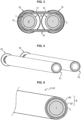
- a device comprises a connector 50 from which two charging cables 61, 62 extend towards the battery (not shown).
- the charging cables 61, 62 exit the terminals of the connector 50 independently of each other. They are not surrounded by any sheath or tube as is the case in the prior art (see figure 2 ). In this way, the charging cables 61, 62 can route independently of each other inside the vehicle to reach the battery and thus pass through independent spaces. This makes it easier to install the charging device.
- Each charging cable comprises, as discussed above, an electrical conductor 8 surrounded by an insulating layer 9.
- the electrical conductor 8 is, for example, made of copper, a copper alloy, aluminum or an aluminum alloy, etc.
- the insulating layer 9 is for example made of thermoplastic material, PVC (lead-free polyvinyl chloride), XLPE (cross-linked polyethylene), etc.
- each charging cable is identical in order to have a homogeneous distribution of intensity.
- the charging cables are not surrounded together by one or more braids but are surrounded individually by a protective device G comprising one or two sheaths G1, G2.
- a protective device G comprising one or two sheaths G1, G2.
- the protection device G comprises a first sheath G1 and possibly a second sheath G2. It will be understood that the notion of sheath used here is in no way comparable to any braid.
- one charging cable may be surrounded by two sheaths while the other is surrounded by a single sheath.
- Each sheath is advantageously arranged according to an extrusion or co-extrusion process in order to be in non-adherent contact with the layer on which it is arranged.
- the non-adherent contact contributes to facilitating the installation of the charging device, in particular for stripping the charging cable for its connection to the battery.
- the sheath can be heat shrinkable.
- the sheath is in non-adherent contact with the insulating layer 9 of the charging cable while in the case of a protective device with two sheaths G1, G2 the second sheath is in non-adherent contact with the first sheath G1.
- the sheath is in intimate contact with the layer on which it is deposited and makes it possible to avoid having air gaps. Indeed, returning to the figure 3 which shows two cables grouped in two braids 30, air blades 70 are present between the cables but also between the braids.
- Each G1, G2 sheath is made of a homogeneous polymeric material and is for example made of material: PVC (lead-free polyvinyl chloride), XLPE (cross-linked polyethylene), etc.
- each sheath is made of a different material.
- Each type of sheath responds independently to the constraints (electrical, mechanical, thermal) which are difficult to verify with a single type of material.
- Each sheath may have a radial thickness of between 0.5 mm and 1.5 mm, preferably 0.7 mm or 1 mm. Furthermore, it may be provided that in the case of a protection device comprising two sheaths G1, G2 do not have the same radial thickness. Of course, the thickness of the two sheaths may be identical. The greater the thickness of at least one sheath, the more the section of the cable increases and promotes heat dissipation.
- the first sheath G1 may have a radial thickness greater or less than the thickness of the second sheath G2.
Landscapes
- Engineering & Computer Science (AREA)
- Power Engineering (AREA)
- Transportation (AREA)
- Mechanical Engineering (AREA)
- Electric Propulsion And Braking For Vehicles (AREA)
- Charge And Discharge Circuits For Batteries Or The Like (AREA)
- Secondary Cells (AREA)
Claims (8)
- Schnellladevorrichtung für ein Hybrid- oder Elektrofahrzeug, die dazu bestimmt ist, einerseits an ein Stromverteilungsnetz (2) und andererseits an die Klemmen einer Batterie (10) eines Hybrid- oder Elektrofahrzeugs angeschlossen zu werden, wobei die Vorrichtung umfasst- zwei Ladekabel (61, 62), die geeignet sind, unabhängig voneinander im Inneren eines Fahrzeugs zu verlaufen, wobei die zwei Kabel nicht von einer wie auch immer gearteten Hülle oder Schlauch umgeben sind, die/der beiden Kabeln gemeinsam ist;- einen Verbinder (50), der einen Eingang umfasst, der dazu bestimmt ist, an ein Versorgungskabel angeschlossen zu sein, das selbst dazu bestimmt ist, an ein Stromverteilungsnetz angeschlossen zu sein, und einen Ausgang, von dem aus sich die Ladekabel erstrecken;wobei jedes der beiden Kabel dazu bestimmt ist, an eine Klemme der Batterie an einem Ende des Kabels und am anderen Ende an ein jeweiliges Endstück des Ausgangs des Verbinders (50) angeschlossen zu werden,wobei jedes Ladekabel (61, 62) einen elektrischen Leiter (8) und mindestens eine den elektrischen Leiter (8) umgebende Isolierschicht (9) umfasst, wobei die Isolierschicht (9) in direktem Kontakt mit dem elektrischen Leiter (8) ist; wobei jedes Ladekabel ferner eine Schutzvorrichtung (G) umfasst, die aus mindestens einer Hülle (G1, G2) besteht, die um die Isolierschicht herum angeordnet ist und sich an die von dem elektrischen Leiter (8) und der Isolierschicht (9) gebildete Anordnung anpasst, wobei eine Hülle der mindestens einen Hülle der Schutzvorrichtung (G) in direktem Kontakt mit der Isolierschicht derart ist, dass die Ableitung von Wärme von der Ladevorrichtung in das Innere des Fahrzeugs und im Bereich des Verbinders gefördert wird.
- Ladevorrichtung nach Anspruch 1, wobei die mindestens eine Hülle durch ein Extrusions- oder Koextrusionsverfahren so angeordnet ist, dass sie in engem, nicht haftendem Kontakt mit der Schicht steht, auf der die Hülle angeordnet ist.
- Ladevorrichtung nach Anspruch 1, wobei die mindestens eine Hülle eine Hülle ist, die derart wärmeschrumpfbar ist, dass sie in engem, nicht haftendem Kontakt mit der Schicht steht, auf der die Hülle angeordnet ist.
- Ladevorrichtung nach einem der Ansprüche 1 bis 3, wobei die Schutzvorrichtung (G) ferner eine zweite Hülle (G2) umfasst, die mit der ersten Hülle (G1) in Kontakt steht.
- Ladevorrichtung nach Anspruch 4, wobei die erste Hülle (G1) und die zweite Hülle (G2) gleiche oder unterschiedliche radiale Dicken aufweisen.
- Ladevorrichtung nach einem der Ansprüche 4 bis 5, wobei die erste Hülle (G1) und die zweite Hülle (G2) aus gleichem oder unterschiedlichem Material sind.
- Ladevorrichtung nach einem der Ansprüche 4 bis 5, wobei die erste Hülle (G1) und gegebenenfalls die zweite Hülle (G2) aus einem Material ist, das aus thermoplastischen Polymeren, beispielsweise Polyvinylchlorid, Polyethylen ausgewählt ist.
- Ladeanordnung für ein Hybrid- oder Elektrofahrzeug, umfassend eine Ladevorrichtung nach einem der vorhergehenden Ansprüche und ein Versorgungskabel, das bestimmt ist, an ein Stromversorgungsnetz angeschlossen zu werden.
Applications Claiming Priority (2)
| Application Number | Priority Date | Filing Date | Title |
|---|---|---|---|
| FR1905372A FR3096314B1 (fr) | 2019-05-22 | 2019-05-22 | Dispositif de charge rapide pour véhicule électrique ou hybride |
| PCT/EP2020/064326 WO2020234467A1 (fr) | 2019-05-22 | 2020-05-22 | Dispositif de charge rapide pour véhicule électrique ou hybride |
Publications (3)
| Publication Number | Publication Date |
|---|---|
| EP3973554A1 EP3973554A1 (de) | 2022-03-30 |
| EP3973554B1 true EP3973554B1 (de) | 2024-12-11 |
| EP3973554C0 EP3973554C0 (de) | 2024-12-11 |
Family
ID=67999833
Family Applications (1)
| Application Number | Title | Priority Date | Filing Date |
|---|---|---|---|
| EP20726171.0A Active EP3973554B1 (de) | 2019-05-22 | 2020-05-22 | Schnelladevorrichtung für ein elektro- oder hybridfahrzeug |
Country Status (7)
| Country | Link |
|---|---|
| US (1) | US12617302B2 (de) |
| EP (1) | EP3973554B1 (de) |
| CN (1) | CN114026659A (de) |
| BR (1) | BR112021026153A2 (de) |
| ES (1) | ES3009338T3 (de) |
| FR (1) | FR3096314B1 (de) |
| WO (1) | WO2020234467A1 (de) |
Citations (10)
| Publication number | Priority date | Publication date | Assignee | Title |
|---|---|---|---|---|
| EP1033725A1 (de) * | 1999-03-01 | 2000-09-06 | HUBER & SUHNER AG | Keramisierende flammwidrige Isolationsmischung für Kabel |
| CN102637480A (zh) * | 2012-04-20 | 2012-08-15 | 淮南新光神光纤线缆有限公司 | 一种新能源汽车用动力电缆 |
| EP2711247A1 (de) * | 2011-05-17 | 2014-03-26 | Nissan Motor Co., Ltd | Routingstruktur für einen ladungs-/entladungskabelbaum für elektroautos |
| CN105702357A (zh) * | 2014-12-15 | 2016-06-22 | 住友电气工业株式会社 | 电线、使用该电线的屏蔽电线以及多芯电缆 |
| US20160276064A1 (en) * | 2013-07-02 | 2016-09-22 | Yazaki Corporation | Wire Harness |
| CN106910555A (zh) * | 2017-04-10 | 2017-06-30 | 安徽凌宇电缆科技有限公司 | 新能源汽车充电桩电缆 |
| KR20180001733A (ko) * | 2016-06-28 | 2018-01-05 | 가온전선 주식회사 | 전기차용 고전압 케이블 |
| WO2018179866A1 (ja) * | 2017-03-28 | 2018-10-04 | 矢崎総業株式会社 | ワイヤハーネス、及び、蓄電装置ユニット |
| CN108944533A (zh) * | 2018-07-27 | 2018-12-07 | 北京新能源汽车股份有限公司 | 用于车辆的冷却系统和具有该冷却系统的车辆 |
| CN109326375A (zh) * | 2018-09-29 | 2019-02-12 | 安徽太平洋电缆股份有限公司 | 柔性超a类铝合金芯新能源汽车用车内高压电缆 |
Family Cites Families (15)
| Publication number | Priority date | Publication date | Assignee | Title |
|---|---|---|---|---|
| JP2007005137A (ja) | 2005-06-23 | 2007-01-11 | Sumitomo Electric Ind Ltd | ケーブル及びその製造方法 |
| CN200950363Y (zh) | 2005-12-13 | 2007-09-19 | 邵耀宗 | 10千伏铝芯塑料分阶绝缘聚乙烯护套电力电缆 |
| JP5170867B2 (ja) | 2007-10-26 | 2013-03-27 | プライムアースEvエナジー株式会社 | 組電池構造体および接続ケーブル |
| FR2946789B1 (fr) * | 2009-06-11 | 2017-01-13 | Nexans | Cable electrique apte a assurer la continuite de distribution electrique en cas d'incendie. |
| US8350526B2 (en) | 2011-07-25 | 2013-01-08 | Lightening Energy | Station for rapidly charging an electric vehicle battery |
| CN202694828U (zh) * | 2012-02-16 | 2013-01-23 | 无锡鑫宏业特塑线缆有限公司 | 电动汽车电池高压线 |
| JP5874549B2 (ja) | 2012-06-29 | 2016-03-02 | 三菱自動車工業株式会社 | 電動車両 |
| US9663098B2 (en) * | 2013-05-29 | 2017-05-30 | Nissan Motor Co., Ltd. | Control system for a plug-in hybrid vehicle |
| JP6361329B2 (ja) | 2014-07-04 | 2018-07-25 | 三菱自動車工業株式会社 | バッテリパックのケーブル接続構造 |
| CN107645621A (zh) | 2016-07-20 | 2018-01-30 | 阿里巴巴集团控股有限公司 | 一种视频处理的方法和设备 |
| KR20180001733U (ko) | 2016-12-02 | 2018-06-12 | 이효인 | 빗물 튐 방지용 신발 덮개 |
| JP6437510B2 (ja) * | 2016-12-19 | 2018-12-12 | 株式会社オートネットワーク技術研究所 | ワイヤハーネス |
| US10826050B1 (en) * | 2017-08-15 | 2020-11-03 | National Technology & Engineering Solutions Of Sandia, Llc | Methods of preparing a safety battery |
| CN109600960B (zh) * | 2017-09-30 | 2020-12-25 | 比亚迪股份有限公司 | 车辆的充电装置以及车辆 |
| CN108447600A (zh) | 2018-04-12 | 2018-08-24 | 天津大学 | 舰船用高导热低温升消磁电缆及其制造方法 |
-
2019
- 2019-05-22 FR FR1905372A patent/FR3096314B1/fr active Active
-
2020
- 2020-05-22 US US17/621,763 patent/US12617302B2/en active Active
- 2020-05-22 BR BR112021026153A patent/BR112021026153A2/pt unknown
- 2020-05-22 ES ES20726171T patent/ES3009338T3/es active Active
- 2020-05-22 CN CN202080037725.1A patent/CN114026659A/zh active Pending
- 2020-05-22 WO PCT/EP2020/064326 patent/WO2020234467A1/fr not_active Ceased
- 2020-05-22 EP EP20726171.0A patent/EP3973554B1/de active Active
Patent Citations (10)
| Publication number | Priority date | Publication date | Assignee | Title |
|---|---|---|---|---|
| EP1033725A1 (de) * | 1999-03-01 | 2000-09-06 | HUBER & SUHNER AG | Keramisierende flammwidrige Isolationsmischung für Kabel |
| EP2711247A1 (de) * | 2011-05-17 | 2014-03-26 | Nissan Motor Co., Ltd | Routingstruktur für einen ladungs-/entladungskabelbaum für elektroautos |
| CN102637480A (zh) * | 2012-04-20 | 2012-08-15 | 淮南新光神光纤线缆有限公司 | 一种新能源汽车用动力电缆 |
| US20160276064A1 (en) * | 2013-07-02 | 2016-09-22 | Yazaki Corporation | Wire Harness |
| CN105702357A (zh) * | 2014-12-15 | 2016-06-22 | 住友电气工业株式会社 | 电线、使用该电线的屏蔽电线以及多芯电缆 |
| KR20180001733A (ko) * | 2016-06-28 | 2018-01-05 | 가온전선 주식회사 | 전기차용 고전압 케이블 |
| WO2018179866A1 (ja) * | 2017-03-28 | 2018-10-04 | 矢崎総業株式会社 | ワイヤハーネス、及び、蓄電装置ユニット |
| CN106910555A (zh) * | 2017-04-10 | 2017-06-30 | 安徽凌宇电缆科技有限公司 | 新能源汽车充电桩电缆 |
| CN108944533A (zh) * | 2018-07-27 | 2018-12-07 | 北京新能源汽车股份有限公司 | 用于车辆的冷却系统和具有该冷却系统的车辆 |
| CN109326375A (zh) * | 2018-09-29 | 2019-02-12 | 安徽太平洋电缆股份有限公司 | 柔性超a类铝合金芯新能源汽车用车内高压电缆 |
Also Published As
| Publication number | Publication date |
|---|---|
| BR112021026153A2 (pt) | 2022-03-03 |
| ES3009338T3 (en) | 2025-03-26 |
| US12617302B2 (en) | 2026-05-05 |
| FR3096314B1 (fr) | 2021-05-21 |
| FR3096314A1 (fr) | 2020-11-27 |
| EP3973554C0 (de) | 2024-12-11 |
| WO2020234467A1 (fr) | 2020-11-26 |
| EP3973554A1 (de) | 2022-03-30 |
| US20220332203A1 (en) | 2022-10-20 |
| CN114026659A (zh) | 2022-02-08 |
Similar Documents
| Publication | Publication Date | Title |
|---|---|---|
| EP2765581B1 (de) | Elektrisches Kabel, das resistent gegen Teilentladungen ist | |
| EP3812199B1 (de) | Kabel mit verbesserter wärmeableitung | |
| EP2859633B1 (de) | Vorrichtung mit einer ladungsblockierungsschicht | |
| FR2979032A1 (fr) | Cable electrique resistant aux decharges partielles | |
| EP3772140A1 (de) | Elektrischer anschluss und elektrische verbindungsvorrichtung | |
| EP4092689A1 (de) | Elektrisches kabel, das teilentladungen begrenzt | |
| JP2016511918A (ja) | 絶縁高電圧dc終端部またはジョイントの製造における方法 | |
| WO2010139886A1 (fr) | Dispositif de liaison entre un connecteur electrique et un cable electrique coaxial blinde et connecteur electrique correspondant | |
| FR3081614A1 (fr) | Module photovoltaique comportant une ou plusieurs diodes de bypass en face arriere d'une cellule photovoltaique du module | |
| WO2020234467A1 (fr) | Dispositif de charge rapide pour véhicule électrique ou hybride | |
| EP0644641B1 (de) | Garnitur zum Verbinden eines Energiekabels und damit ausgerüstetes Energiekabel | |
| EP2911162B1 (de) | Hybridstromkabel | |
| FR3102605A1 (fr) | Câble à dissipation active thermique améliorée | |
| FR3099652A1 (fr) | Dispositif de refroidissement passif pour câble électrique | |
| FR3110781A1 (fr) | Connecteur électrique à contrôle d’isolation | |
| EP3024092A1 (de) | Zusammenbau einer anordnung von elektrischen anschlüssen | |
| FR3094552A1 (fr) | Dispositif de charge pour véhicule électrique à dissipation thermique améliorée | |
| EP2299454B1 (de) | Kabel mit Mitteln zur Detektion von elektrisch leitenden Körpern außerhalb des Kabels | |
| WO2014102097A1 (fr) | Connecteur electrique et machine electrique comportant un tel connecteur | |
| EP1164396A1 (de) | Faseroptisches Kabel | |
| EP4128307B1 (de) | Stromversorgungskabel mit einer schmelzsicherung und einem umspritzten element zum schutz der umspritzten schmelzsicherung | |
| FR2852746A1 (fr) | Systeme de transmission d'energie a haute tension | |
| FR3110279A1 (fr) | Procédé de modification d’un câble électrique pour un véhicule | |
| FR3102604A1 (fr) | Câble électrique à dissipation passive thermique améliorée | |
| WO2025073404A1 (fr) | Câble électrique de puissance haute fréquence et haute tension |
Legal Events
| Date | Code | Title | Description |
|---|---|---|---|
| STAA | Information on the status of an ep patent application or granted ep patent |
Free format text: STATUS: UNKNOWN |
|
| STAA | Information on the status of an ep patent application or granted ep patent |
Free format text: STATUS: THE INTERNATIONAL PUBLICATION HAS BEEN MADE |
|
| PUAI | Public reference made under article 153(3) epc to a published international application that has entered the european phase |
Free format text: ORIGINAL CODE: 0009012 |
|
| STAA | Information on the status of an ep patent application or granted ep patent |
Free format text: STATUS: REQUEST FOR EXAMINATION WAS MADE |
|
| 17P | Request for examination filed |
Effective date: 20211220 |
|
| AK | Designated contracting states |
Kind code of ref document: A1 Designated state(s): AL AT BE BG CH CY CZ DE DK EE ES FI FR GB GR HR HU IE IS IT LI LT LU LV MC MK MT NL NO PL PT RO RS SE SI SK SM TR |
|
| DAV | Request for validation of the european patent (deleted) | ||
| DAX | Request for extension of the european patent (deleted) | ||
| P01 | Opt-out of the competence of the unified patent court (upc) registered |
Effective date: 20230427 |
|
| STAA | Information on the status of an ep patent application or granted ep patent |
Free format text: STATUS: EXAMINATION IS IN PROGRESS |
|
| 17Q | First examination report despatched |
Effective date: 20230614 |
|
| GRAP | Despatch of communication of intention to grant a patent |
Free format text: ORIGINAL CODE: EPIDOSNIGR1 |
|
| STAA | Information on the status of an ep patent application or granted ep patent |
Free format text: STATUS: GRANT OF PATENT IS INTENDED |
|
| INTG | Intention to grant announced |
Effective date: 20240715 |
|
| GRAS | Grant fee paid |
Free format text: ORIGINAL CODE: EPIDOSNIGR3 |
|
| GRAA | (expected) grant |
Free format text: ORIGINAL CODE: 0009210 |
|
| STAA | Information on the status of an ep patent application or granted ep patent |
Free format text: STATUS: THE PATENT HAS BEEN GRANTED |
|
| AK | Designated contracting states |
Kind code of ref document: B1 Designated state(s): AL AT BE BG CH CY CZ DE DK EE ES FI FR GB GR HR HU IE IS IT LI LT LU LV MC MK MT NL NO PL PT RO RS SE SI SK SM TR |
|
| REG | Reference to a national code |
Ref country code: GB Ref legal event code: FG4D Free format text: NOT ENGLISH |
|
| REG | Reference to a national code |
Ref country code: CH Ref legal event code: EP |
|
| REG | Reference to a national code |
Ref country code: IE Ref legal event code: FG4D Free format text: LANGUAGE OF EP DOCUMENT: FRENCH |
|
| REG | Reference to a national code |
Ref country code: DE Ref legal event code: R096 Ref document number: 602020042937 Country of ref document: DE |
|
| U01 | Request for unitary effect filed |
Effective date: 20241227 |
|
| U07 | Unitary effect registered |
Designated state(s): AT BE BG DE DK EE FI FR IT LT LU LV MT NL PT RO SE SI Effective date: 20250114 |
|
| P04 | Withdrawal of opt-out of the competence of the unified patent court (upc) registered |
Free format text: CASE NUMBER: APP_1578/2025 Effective date: 20250110 |
|
| REG | Reference to a national code |
Ref country code: ES Ref legal event code: FG2A Ref document number: 3009338 Country of ref document: ES Kind code of ref document: T3 Effective date: 20250326 |
|
| PG25 | Lapsed in a contracting state [announced via postgrant information from national office to epo] |
Ref country code: HR Free format text: LAPSE BECAUSE OF FAILURE TO SUBMIT A TRANSLATION OF THE DESCRIPTION OR TO PAY THE FEE WITHIN THE PRESCRIBED TIME-LIMIT Effective date: 20241211 |
|
| PG25 | Lapsed in a contracting state [announced via postgrant information from national office to epo] |
Ref country code: NO Free format text: LAPSE BECAUSE OF FAILURE TO SUBMIT A TRANSLATION OF THE DESCRIPTION OR TO PAY THE FEE WITHIN THE PRESCRIBED TIME-LIMIT Effective date: 20250311 |
|
| PG25 | Lapsed in a contracting state [announced via postgrant information from national office to epo] |
Ref country code: GR Free format text: LAPSE BECAUSE OF FAILURE TO SUBMIT A TRANSLATION OF THE DESCRIPTION OR TO PAY THE FEE WITHIN THE PRESCRIBED TIME-LIMIT Effective date: 20250312 |
|
| PG25 | Lapsed in a contracting state [announced via postgrant information from national office to epo] |
Ref country code: RS Free format text: LAPSE BECAUSE OF FAILURE TO SUBMIT A TRANSLATION OF THE DESCRIPTION OR TO PAY THE FEE WITHIN THE PRESCRIBED TIME-LIMIT Effective date: 20250311 |
|
| U20 | Renewal fee for the european patent with unitary effect paid |
Year of fee payment: 6 Effective date: 20250527 |
|
| PG25 | Lapsed in a contracting state [announced via postgrant information from national office to epo] |
Ref country code: SM Free format text: LAPSE BECAUSE OF FAILURE TO SUBMIT A TRANSLATION OF THE DESCRIPTION OR TO PAY THE FEE WITHIN THE PRESCRIBED TIME-LIMIT Effective date: 20241211 |
|
| PG25 | Lapsed in a contracting state [announced via postgrant information from national office to epo] |
Ref country code: PL Free format text: LAPSE BECAUSE OF FAILURE TO SUBMIT A TRANSLATION OF THE DESCRIPTION OR TO PAY THE FEE WITHIN THE PRESCRIBED TIME-LIMIT Effective date: 20241211 |
|
| PG25 | Lapsed in a contracting state [announced via postgrant information from national office to epo] |
Ref country code: IS Free format text: LAPSE BECAUSE OF FAILURE TO SUBMIT A TRANSLATION OF THE DESCRIPTION OR TO PAY THE FEE WITHIN THE PRESCRIBED TIME-LIMIT Effective date: 20250411 |
|
| PG25 | Lapsed in a contracting state [announced via postgrant information from national office to epo] |
Ref country code: SK Free format text: LAPSE BECAUSE OF FAILURE TO SUBMIT A TRANSLATION OF THE DESCRIPTION OR TO PAY THE FEE WITHIN THE PRESCRIBED TIME-LIMIT Effective date: 20241211 |
|
| PG25 | Lapsed in a contracting state [announced via postgrant information from national office to epo] |
Ref country code: CZ Free format text: LAPSE BECAUSE OF FAILURE TO SUBMIT A TRANSLATION OF THE DESCRIPTION OR TO PAY THE FEE WITHIN THE PRESCRIBED TIME-LIMIT Effective date: 20241211 |
|
| PLBE | No opposition filed within time limit |
Free format text: ORIGINAL CODE: 0009261 |
|
| STAA | Information on the status of an ep patent application or granted ep patent |
Free format text: STATUS: NO OPPOSITION FILED WITHIN TIME LIMIT |
|
| REG | Reference to a national code |
Ref country code: CH Ref legal event code: L10 Free format text: ST27 STATUS EVENT CODE: U-0-0-L10-L00 (AS PROVIDED BY THE NATIONAL OFFICE) Effective date: 20251022 |
|
| 26N | No opposition filed |
Effective date: 20250912 |
|
| REG | Reference to a national code |
Ref country code: CH Ref legal event code: H13 Free format text: ST27 STATUS EVENT CODE: U-0-0-H10-H13 (AS PROVIDED BY THE NATIONAL OFFICE) Effective date: 20251223 |
|
| PG25 | Lapsed in a contracting state [announced via postgrant information from national office to epo] |
Ref country code: CH Free format text: LAPSE BECAUSE OF NON-PAYMENT OF DUE FEES Effective date: 20250531 |
|
| PG25 | Lapsed in a contracting state [announced via postgrant information from national office to epo] |
Ref country code: MC Free format text: LAPSE BECAUSE OF FAILURE TO SUBMIT A TRANSLATION OF THE DESCRIPTION OR TO PAY THE FEE WITHIN THE PRESCRIBED TIME-LIMIT Effective date: 20241211 |
|
| PG25 | Lapsed in a contracting state [announced via postgrant information from national office to epo] |
Ref country code: IE Free format text: LAPSE BECAUSE OF NON-PAYMENT OF DUE FEES Effective date: 20250522 |
|
| U20 | Renewal fee for the european patent with unitary effect paid |
Year of fee payment: 7 Effective date: 20260428 |
|
| PGFP | Annual fee paid to national office [announced via postgrant information from national office to epo] |
Ref country code: ES Payment date: 20260608 Year of fee payment: 7 |
|
| PGFP | Annual fee paid to national office [announced via postgrant information from national office to epo] |
Ref country code: GB Payment date: 20260521 Year of fee payment: 7 |
|
| PG25 | Lapsed in a contracting state [announced via postgrant information from national office to epo] |
Ref country code: CY Free format text: LAPSE BECAUSE OF FAILURE TO SUBMIT A TRANSLATION OF THE DESCRIPTION OR TO PAY THE FEE WITHIN THE PRESCRIBED TIME-LIMIT Effective date: 20241211 |