EP3973100B1 - Corde ayant un segment de connecteur d'extrémité comprenant deux branches de corde de longueurs inégales - Google Patents
Corde ayant un segment de connecteur d'extrémité comprenant deux branches de corde de longueurs inégales Download PDFInfo
- Publication number
- EP3973100B1 EP3973100B1 EP20708213.2A EP20708213A EP3973100B1 EP 3973100 B1 EP3973100 B1 EP 3973100B1 EP 20708213 A EP20708213 A EP 20708213A EP 3973100 B1 EP3973100 B1 EP 3973100B1
- Authority
- EP
- European Patent Office
- Prior art keywords
- rope
- branch
- strands
- eye
- segment
- Prior art date
- Legal status (The legal status is an assumption and is not a legal conclusion. Google has not performed a legal analysis and makes no representation as to the accuracy of the status listed.)
- Active
Links
- 238000004519 manufacturing process Methods 0.000 claims description 16
- 238000000034 method Methods 0.000 claims description 11
- 239000007779 soft material Substances 0.000 claims description 4
- 238000010168 coupling process Methods 0.000 description 9
- 230000008878 coupling Effects 0.000 description 7
- 238000005859 coupling reaction Methods 0.000 description 7
- 238000010276 construction Methods 0.000 description 5
- 230000002349 favourable effect Effects 0.000 description 4
- 238000009954 braiding Methods 0.000 description 2
- 230000005484 gravity Effects 0.000 description 2
- 239000000463 material Substances 0.000 description 2
- 230000003252 repetitive effect Effects 0.000 description 2
- 230000001419 dependent effect Effects 0.000 description 1
- 238000004904 shortening Methods 0.000 description 1
Images


Classifications
-
- D—TEXTILES; PAPER
- D07—ROPES; CABLES OTHER THAN ELECTRIC
- D07B—ROPES OR CABLES IN GENERAL
- D07B1/00—Constructional features of ropes or cables
- D07B1/18—Grommets
-
- D—TEXTILES; PAPER
- D07—ROPES; CABLES OTHER THAN ELECTRIC
- D07B—ROPES OR CABLES IN GENERAL
- D07B1/00—Constructional features of ropes or cables
- D07B1/18—Grommets
- D07B1/185—Grommets characterised by the eye construction
-
- B—PERFORMING OPERATIONS; TRANSPORTING
- B66—HOISTING; LIFTING; HAULING
- B66C—CRANES; LOAD-ENGAGING ELEMENTS OR DEVICES FOR CRANES, CAPSTANS, WINCHES, OR TACKLES
- B66C1/00—Load-engaging elements or devices attached to lifting or lowering gear of cranes or adapted for connection therewith for transmitting lifting forces to articles or groups of articles
- B66C1/10—Load-engaging elements or devices attached to lifting or lowering gear of cranes or adapted for connection therewith for transmitting lifting forces to articles or groups of articles by mechanical means
- B66C1/12—Slings comprising chains, wires, ropes, or bands; Nets
-
- F—MECHANICAL ENGINEERING; LIGHTING; HEATING; WEAPONS; BLASTING
- F16—ENGINEERING ELEMENTS AND UNITS; GENERAL MEASURES FOR PRODUCING AND MAINTAINING EFFECTIVE FUNCTIONING OF MACHINES OR INSTALLATIONS; THERMAL INSULATION IN GENERAL
- F16G—BELTS, CABLES, OR ROPES, PREDOMINANTLY USED FOR DRIVING PURPOSES; CHAINS; FITTINGS PREDOMINANTLY USED THEREFOR
- F16G11/00—Means for fastening cables or ropes to one another or to other objects; Caps or sleeves for fixing on cables or ropes
- F16G11/14—Devices or coupling-pieces designed for easy formation of adjustable loops, e.g. choker hooks; Hooks or eyes with integral parts designed to facilitate quick attachment to cables or ropes at any point, e.g. by forming loops
-
- F—MECHANICAL ENGINEERING; LIGHTING; HEATING; WEAPONS; BLASTING
- F16—ENGINEERING ELEMENTS AND UNITS; GENERAL MEASURES FOR PRODUCING AND MAINTAINING EFFECTIVE FUNCTIONING OF MACHINES OR INSTALLATIONS; THERMAL INSULATION IN GENERAL
- F16G—BELTS, CABLES, OR ROPES, PREDOMINANTLY USED FOR DRIVING PURPOSES; CHAINS; FITTINGS PREDOMINANTLY USED THEREFOR
- F16G15/00—Chain couplings, Shackles; Chain joints; Chain links; Chain bushes
- F16G15/04—Quickly-detachable chain couplings; Shackles chain links with rapid junction means are classified according to the corresponding kind of chain
- F16G15/06—Shackles designed for attachment by joint pins to chain elements, e.g. D-shackles so called harp links; the D-chain links are classified according to the corresponding kind of chain
-
- D—TEXTILES; PAPER
- D07—ROPES; CABLES OTHER THAN ELECTRIC
- D07B—ROPES OR CABLES IN GENERAL
- D07B2201/00—Ropes or cables
- D07B2201/10—Rope or cable structures
- D07B2201/1004—General structure or appearance
Definitions
- the invention relates to a rope, wherein the rope along a longitudinal rope direction of the rope towards a longitudinal rope end of the rope successively comprises at least a main rope segment, a branching position and an end connector segment, wherein:
- the invention further relates to use of such a rope, as well as to a method of manufacturing such a rope.
- the rope according to the invention may be used offshore as well as onshore, for example as a lifting rope, a towing rope, a mooring rope, or the like.
- a rope of the type as initially identified above is known from WO 2012/150469 A2 . See for example the rope 100 or the rope 200 of Fig. 9 of the Abstract of WO 2012/150469 A2 . It is seen that said rope 100 has the end connector segment 116 having the first rope-branch-eye 50 and the second rope-branch-eye 52. Similarly, said rope 200 has the end connector segment 216 having the first rope-branch-eye 250 and the second rope-branch-eye 252. It is further seen that a connecting component in the form of the shown connecting spool 58 can be used to connect the ropes 100 and 200 together end-to-end.
- the invention provides a rope according to the appended independent claim 1, use of such a rope according to the appended independent claim 4, and a method of manufacturing such a rope according to the appended independent claim 6.
- Specific embodiments of the invention are set forth in the appended dependent claims 2, 3, 5, 7 and 8.
- the invention provides a rope, wherein the rope along a longitudinal rope direction of the rope towards a longitudinal rope end of the rope successively comprises at least a main rope segment, a branching position and an end connector segment, wherein:
- an attainable maximum first effective length of the first rope-branch equals a vertical first length along the first rope-branch as measured in a first reference condition of the rope, wherein in said first reference condition the first rope-branch, as well as its first rope-branch-eye, are as much as possible in a first plumb line configuration, in which the very end of the first rope-branch-eye corresponds to the lowest part of the first rope-branch-eye and is considered to be a concentrated first plumb mass point of the first plumb line configuration, and wherein said vertical first length is measured from the branching position up to said very end of the first rope-branch-eye.
- an attainable maximum second effective length of the second rope-branch equals a vertical second length along the second rope-branch as measured in a second reference condition of the rope, wherein in said second reference condition the second rope-branch, as well as its second rope-branch-eye, are as much as possible in a second plumb line configuration, in which the very end of the second rope-branch-eye corresponds to the lowest part of the second rope-branch-eye and is considered to be a concentrated second plumb mass point of the second plumb line configuration, and wherein said vertical second length is measured from the branching position up to said very end of the second rope-branch-eye.
- the attainable maximum first effective length of the first rope-branch is higher than 120% of the attainable maximum second effective length of the second rope-branch.
- the inventors of the present invention have devised that the resulting asymmetry of the end connector segment of a rope according to the invention allows for alternative favourable manners of connecting the rope to other ropes and to other types of external objects. That is, the inventors have devised that a link structure can be used to interconnect the first rope-branch-eye and the second rope-branch-eye, so that the first rope-branch, the second rope-branch and said link structure together will form a rope-eye at said longitudinal rope end of the rope, wherein said rope-eye is suitable for connecting the rope to external objects.
- Said link structure may comprise a link in the form of a shackle of hard and/or soft materials, or wherein said link structure comprises a chain of links, such as a chain of at least two shackles of hard and/or soft materials.
- the rope according to the invention can be used as a lifting rope for a hoisting load which has a lifting lug.
- This can be done as follows. Firstly, the lifting rope can be hung vertically above the hoisting load, with the end connector segment of the rope nearby the lifting lug of the hoisting load. Next, an operator can pass the end of the longer first rope-branch through the lifting lug and then upwards towards the shorter second rope-branch, where a link structure can be effectuated to interconnect the first rope-branch-eye and the second rope-branch-eye, so that the first rope-branch, the second rope-branch and said link structure together will form a rope-eye at the longitudinal rope end of the rope. This way, the formed rope-eye of the rope effectively engages the lifting lug of the hoisting load for lifting purposes.
- the rope known from the above-mentioned document WO 2012/150469 A2 has a symmetrical end connector segment having first and second rope-branches of mutually equal attainable maximum first and second effective lengths, respectively.
- the rope according to the present invention has an asymmetrical end connector segment having first and second rope-branches of mutually unequal attainable maximum first and second effective lengths, respectively.
- An advantage of the mutually unequal maximum effective lengths of the two rope-branches of a rope according to the invention is that the above-mentioned interconnecting link structure is positioned asymmetrically within the formed rope-eye. Thanks to this asymmetrical positioning of the link structure, the link structure only needs to carry roughly half of the load during lifting, as compared to a symmetrically positioned link structure where the link structure would directly engage the lifting lug of the hoisting load. Thanks to this considerably lower loading of the link structure, the link structure can be designed relatively compact and light-weight.
- Another advantage of the mutually unequal maximum effective lengths of the two rope-branches of a rope according to the invention is that it is optionally possible that at least part of the link structure is at least partly pre-mounted to the shorter second rope-branch prior to connecting the rope to the hoisting load.
- This pre-mounting is advantageous in that gravity will keep the at least part of the link structure nicely in place above the hoisting load. This saves a lot of unnecessary movements to be performed with a link structure when connecting the rope to the hoisting load. This is especially favourable in cases of link structures made of heavy materials and in cases of highly repetitive hoisting jobs with many hoisting loads.
- This preferable embodiment of the invention allows to manufacture the rope, including its specifically configured end connector segment, of a more or less continuously stranded rope construction, providing the advantages of a strong and compact rope construction. It also allows for making flexible rope-branch-eyes and thereby it allows for highly interesting uses such as passing rope-branch-eyes through a lifting lug of an object to be hoisted.
- Figs. 1-5 The reference signs used in Figs. 1-5 are referring to the abovementioned parts and aspects of the invention, as well as to related parts and aspects, in the following manner.
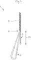
- Fig. 5 illustrates a use, according to the invention, of the rope 1 according to the invention.
- an end portion of the longer first rope-branch 11 has been passed through the lifting lug 9 of an external object in the form of the shown hoisting load 10.
- the link structure 7 has been used to interconnect the first rope-branch-eye 21 and the second rope-branch-eye 22, so that the first rope-branch 11, the second rope-branch 12 and the link structure 7 together are forming the rope-eye 8 at the longitudinal rope end 3 of the rope 1.
- the formed rope-eye 8 is connecting the rope 1 to the hoisting load 10.
- the load is evenly distributed over the left-side and right-side halves of the rope-eye 8.
- the link structure 7 is part of the right-side half of the rope-eye 8. Thanks to this asymmetrical positioning of the link structure 7, the link structure 7 only needs to carry roughly half of the load during lifting, as compared to a considered symmetrically positioned link structure in a considered different rope having a symmetrical end connector segment having first and second rope-branches of mutually equal attainable maximum first and second effective lengths, respectively, where the symmetrically positioned link structure would directly engage the lifting lug 9 of the hoisting load 10. Thanks to this considerably lower loading of the asymmetrically positioned link structure 7 according to the invention, the link structure 7 can be designed relatively compact and light-weight.
- FIG. 6A, 6B, 6C illustrate an example of a first embodiment of a method of manufacturing a rope according to the invention, more specifically a method of manufacturing the rope 1 of Figs. 1-5 .
- the rope 1" of Fig. 6A comprises a main rope segment 4" of, for example, braided or laid rope strands.
- the rope 1" further comprises the branching position 5 and a rope end segment 6".
- the rope end segment 6" comprises twelve rope strands 14. It is noted that the construction of the rope end segment 6" previously was identical to and integral with the rope construction of the main rope segment 4". In fact, the twelve rope strands 14 of the rope end segment 6" as shown in Fig. 6A were obtained by mutually disentangling (for example un-braiding or un-laying) the rope strands of said previously identical and integral rope construction.
- the rope 1' of Fig. 6B has the same main rope segment 4" and the same branching position 5 as the rope 1" of Fig. 6A .
- the rope 1' of Fig. 6B has a rope end segment 6', which is different from the rope end segment 6" of the rope 1" of Fig. 6A . That is, the rope 1' of Fig. 6B has four rope end portions 11A, 11B, 12A, 12B.
- Each of said rope end portions 11A, 11B, 12A, 12B has been obtained by mutually entangling (for example braiding or laying) three of the twelve rope strands 14 of the rope 1" of Fig. 6A .
- the twelve mutually disentangled rope strands 14 in Fig. 6A are shown in four separately arranged groups, each having three mutually disentangled rope strands 14.
- the rope 1 of Fig. 6C is obtained by splicing the rope end portions 11A and 11B of the rope 1' of Fig. 6B end-to-end back into each other to form the first rope-branch 11 having the first rope-branch-eye 21, and by splicing the rope end portions 12A and 12B of the rope 1' of Fig. 6B end-to-end back into each other to form the second rope-branch 12 having the second rope-branch-eye 22.
- said splicings of rope end portions end-to-end back into each other have been highly schematically indicated by the two-way arrows 11C and 12C, respectively.
- Each of said splicings 11C and 12C of rope end portions end-to-end back into each other may for example be performed by, or in combination with, any one of the many various methods disclosed in WO 2011/071387 A1 , such as by, or in combination with, any one of the methods according to any one of the claims 18-34 of WO 2011/071387 A1 .
- each of said splicings 11C and 12C of rope end portions end-to-end back into each other may even be extended with splicing one, more, or all of the rope end portions 11A, 11B, 12A, 12B partly back into the main rope segment 4" of the rope 1' of Fig. 6B to obtain the main rope segment 4 of the rope 1 of Fig. 6C .
- the mutually unequal lengths L1 and L2 of the two rope-branches 11 and 12 of the rope 1 may for example be obtained by shortening the rope strands 14 used for the rope end portions 12A, 12B prior to splicing the rope end portions 12A and 12B of the rope 1' of Fig. 6B end-to-end back into each other to form the second rope-branch 12 having the second rope-branch-eye 22.
- an alternative way of forming the first rope-branch-eye 21 out of the rope end portions 11A and 11B of the rope 1' of Fig. 6B may be realized by using the concept of a "multi-strand coupling rope" as disclosed in the above-mentioned document WO 2012/150469 A2 , such as for example the multi-strand coupling rope 18a shown in Fig. 5 of WO 2012/150469 A2 .
- a multi-strand coupling rope may also be used for forming the second rope-branch-eye 22 out of the rope end portions 12A and 12B of the rope 1' of Fig. 6B .
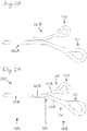
- Figs. 7A, 7B illustrate an example of a second embodiment of a method of manufacturing a rope according to the invention, more specifically a method of manufacturing the rope 101 of Fig. 7B .
- Fig. 7A shows two separate first and second ropes 101A and 101B, respectively.
- the first rope 101A has a first eye 121 at an end of the first rope 101A.
- the rope 101B has a second eye 122 at an end of the second rope 101B.
- Each of the first and second ropes 101A and 101B can be manufactured by many various methods, for example by, or in combination with, any one of the many various methods disclosed in WO 2011/071387 A1 , such as by, or in combination with, any one of the methods according to any one of the claims 18-34 of WO 2011/071387 A1 .
- the rope 101 of Fig. 7B is obtained by splicing a portion of a main rope segment of the rope 101B into a portion of a main rope segment of the rope 101A in such manner that the rope 101 has the shown main rope segment 104, the shown branching position 105 and the shown end connector segment 106 having the shown two rope-branches 111 and 112 of mutually unequal lengths, wherein the first rope-branch 111 comprises the first eye 121 of the first rope 101A as the first rope-branch-eye 121 of the rope 101, and wherein the second rope-branch 112 comprises the second eye 122 of the second rope 101B as the second rope-branch-eye 122 of the rope 101.
- Figs. 8A, 8B illustrate an example of a third embodiment of a method of manufacturing a rope according to the invention, more specifically a method of manufacturing the rope 201 of Fig. 8B .
- Fig. 8A shows a rope 201' of multiple load-bearing sub-ropes 241A, 241B, 242A, 242B within an outer jacket 231.
- the rope 201 of Fig. 8B is obtained by coupling the sub-ropes 241A, 241B together and by coupling the sub-ropes 242A, 242B together, in such manner that the rope 201 has the shown main rope segment 204, the shown branching position 205 and the shown end connector segment 206 having the shown two rope-branches 211 and 212 of mutually unequal lengths, wherein the first rope-branch 211 comprises the shown first rope-branch-eye 221 of the rope 201, and wherein the second rope-branch 212 comprises the shown second rope-branch-eye 222 of the rope 201.
- the main rope segment 4, the first rope-branch 11 and the first rope-branch-eye 21 are each containing the first plurality of strands and the second plurality of strands, while the main rope segment 4, the second rope-branch 12 and the second rope-branch-eye 22 are each containing the third plurality of strands and the fourth plurality of strands.
- the main rope segment 104, the first rope-branch 111 and the first rope-branch-eye 121 are each containing the first plurality of strands and the second plurality of strands
- the main rope segment 104, the second rope-branch 112 and the second rope-branch-eye 122 are each containing the third plurality of strands and the fourth plurality of strands.
- the main rope segment 204, the first rope-branch 211 and the first rope-branch-eye 221 are each containing the first plurality of strands and the second plurality of strands
- the main rope segment 204, the second rope-branch 212 and the second rope-branch-eye 222 are each containing the third plurality of strands and the fourth plurality of strands.
Landscapes
- Engineering & Computer Science (AREA)
- General Engineering & Computer Science (AREA)
- Mechanical Engineering (AREA)
- Lift-Guide Devices, And Elevator Ropes And Cables (AREA)
- Ropes Or Cables (AREA)
Claims (8)
- Corde (1), dans laquelle la corde le long d'une direction de corde longitudinale (2) de la corde vers une extrémité de corde longitudinale (3) de la corde comprend successivement au moins un segment de corde principal (4), une position d'embranchement (5) et un segment de connecteur d'extrémité (6), dans lesquels :- la position d'embranchement (5) est une position fixe le long de la direction de corde longitudinale (2),- le segment de connecteur d'extrémité (4) est formé par toutes les parties de la corde (1) qui, vues dans ladite direction de corde longitudinale (2), s'étendent de la position d'embranchement (5) à l'extrémité de corde longitudinale (3),- le segment de connecteur d'extrémité a deux, et seulement deux, branches de la corde,- lesdites deux branches de la corde consistent en une première branche de corde (11) et une deuxième branche de corde (12), qui se séparent depuis le segment de corde principal au niveau de ladite position d'embranchement, et- la première branche de corde comprend un premier oeil de branche de corde (21) et la deuxième branche de corde comprend un deuxième oeil de branche de corde (22),
caractérisée en ce que- une première longueur efficace maximale atteignable (L1) de la première branche de corde (11) est supérieure à 120 % d'une deuxième longueur efficace maximale atteignable (L2) de la deuxième branche de corde (12). - Corde (1) selon la revendication 1, dans laquelle :- la corde comprend une première pluralité de brins, une deuxième pluralité de brins, une troisième pluralité de brins et une quatrième pluralité de brins,- chaque brin de la première pluralité de brins et de la deuxième pluralité de brins s'étend de façon continue au moins de l'intérieur du segment de corde principal (4) à l'intérieur de la première branche de corde (11),- la première pluralité de brins et la deuxième pluralité de brins sont mises bout à bout pour former une épissure l'une avec l'autre, en formant ainsi au moins partiellement ledit premier oeil de branche de corde (21),- chaque brin de la troisième pluralité de brins et de la quatrième pluralité de brins s'étend de façon continue au moins de l'intérieur du segment de corde principal (4) à l'intérieur de la deuxième branche de corde (12), et- la troisième pluralité de brins et la quatrième pluralité de brins sont mises bout à bout pour former une épissure l'une avec l'autre, en formant ainsi au moins partiellement ledit deuxième oeil de branche de corde (22).
- Corde (1) selon la revendication 1 ou 2, dans laquelle ladite première longueur efficace maximale atteignable (L1) est supérieure à 150 % de ladite deuxième longueur efficace maximale atteignable (L2), de préférence supérieure à 200 % de ladite deuxième longueur efficace maximale atteignable (L2), et mieux encore supérieure à 300 % de ladite deuxième longueur efficace maximale atteignable (L2).
- Utilisation d'une corde (1) selon l'une quelconque des revendications précédentes, dans laquelle une structure de liaison (7) est utilisée pour interconnecter le premier oeil de branche de corde (21) et le deuxième oeil de branche de corde (22), de sorte que la première branche de corde (11), la deuxième branche de corde (12) et ladite structure de liaison (7) forment ensemble un oeil de corde (8) au niveau de ladite extrémité de corde longitudinale (3) de la corde, ledit oeil de corde (8) étant approprié pour attacher la corde à des objets extérieurs (10).
- Utilisation d'une corde (1) selon la revendication 4, dans laquelle ladite structure de liaison (7) comprend un lien sous la forme d'une manille en matériaux durs et/ou mous, ou dans laquelle ladite structure de liaison (7) comprend une chaîne de liens, comme une chaîne d'au moins deux manilles en matériaux durs et/ou mous.
- Procédé de fabrication d'une corde (1), dans lequel le procédé comprend la fabrication d'un segment de corde principal (4) et d'un segment de connecteur d'extrémité (6),de telle manière que la corde (1) le long d'une direction de corde longitudinale (2) de la corde vers une extrémité de corde longitudinale (3) de la corde comprend successivement au moins ledit segment de corde principal (4), une position d'embranchement (5) et ledit segment de connecteur d'extrémité (6), dans lesquels :- la position d'embranchement (5) est une position fixe le long de la direction de corde longitudinale (2),- le segment de connecteur d'extrémité (4) est formé par toutes les parties de la corde (1) qui, vues dans ladite direction de corde longitudinale (2), s'étendent de la position d'embranchement (5) à l'extrémité de corde longitudinale (3),- le segment de connecteur d'extrémité a deux, et seulement deux, branches de la corde,- lesdites deux branches de la corde consistent en une première branche de corde (11) et une deuxième branche de corde (12), qui se séparent depuis le segment de corde principal au niveau de ladite position d'embranchement, et- la première branche de corde comprend un premier oeil de branche de corde (21) et la deuxième branche de corde comprend un deuxième oeil de branche de corde (22),caractérisé en ce queune première longueur efficace maximale atteignable (L1) de la première branche de corde (11) est supérieure à 120 % d'une deuxième longueur efficace maximale atteignable (L2) de la deuxième branche de corde (12).
- Procédé selon la revendication 6, dans lequel :- la corde comprend une première pluralité de brins, une deuxième pluralité de brins, une troisième pluralité de brins et une quatrième pluralité de brins,- chaque brin de la première pluralité de brins et de la deuxième pluralité de brins s'étend de façon continue au moins de l'intérieur du segment de corde principal (4) à l'intérieur de la première branche de corde (11), et- chaque brin de la troisième pluralité de brins et de la quatrième pluralité de brins s'étend de façon continue au moins de l'intérieur du segment de corde principal (4) à l'intérieur de la deuxième branche de corde (12),et dans lequel le procédé comprend les étapes suivantes :- mettre bout à bout la première pluralité de brins et la deuxième pluralité de brins pour former une épissure l'une avec l'autre, en formant ainsi au moins partiellement le premier oeil de branche de corde (21), et- mettre bout à bout la troisième pluralité de brins et la quatrième pluralité de brins pour former une épissure l'une avec l'autre, en formant ainsi au moins partiellement le deuxième oeil de branche de corde (22).
- Procédé selon la revendication 6 ou 7', dans lequel ladite première longueur efficace maximale atteignable (L1) est supérieure à 150 % de ladite deuxième longueur efficace maximale atteignable (L2), de préférence supérieure à 200 % de ladite deuxième longueur efficace maximale atteignable (L2), et mieux encore supérieure à 300 % de ladite deuxième longueur efficace maximale atteignable (L2).
Applications Claiming Priority (2)
| Application Number | Priority Date | Filing Date | Title |
|---|---|---|---|
| EP19175709.5A EP3741911A1 (fr) | 2019-05-21 | 2019-05-21 | Corde ayant un segment de connecteur d'extrémité comprenant deux branches de corde de longueurs inégales |
| PCT/NL2020/050114 WO2020235993A1 (fr) | 2019-05-21 | 2020-02-24 | Corde ayant un segment de connecteur d'extrémité comprenant deux branches de corde de longueurs inégales |
Publications (2)
| Publication Number | Publication Date |
|---|---|
| EP3973100A1 EP3973100A1 (fr) | 2022-03-30 |
| EP3973100B1 true EP3973100B1 (fr) | 2022-11-23 |
Family
ID=66630124
Family Applications (2)
| Application Number | Title | Priority Date | Filing Date |
|---|---|---|---|
| EP19175709.5A Withdrawn EP3741911A1 (fr) | 2019-05-21 | 2019-05-21 | Corde ayant un segment de connecteur d'extrémité comprenant deux branches de corde de longueurs inégales |
| EP20708213.2A Active EP3973100B1 (fr) | 2019-05-21 | 2020-02-24 | Corde ayant un segment de connecteur d'extrémité comprenant deux branches de corde de longueurs inégales |
Family Applications Before (1)
| Application Number | Title | Priority Date | Filing Date |
|---|---|---|---|
| EP19175709.5A Withdrawn EP3741911A1 (fr) | 2019-05-21 | 2019-05-21 | Corde ayant un segment de connecteur d'extrémité comprenant deux branches de corde de longueurs inégales |
Country Status (5)
| Country | Link |
|---|---|
| US (1) | US20220081832A1 (fr) |
| EP (2) | EP3741911A1 (fr) |
| AU (1) | AU2020280872A1 (fr) |
| DK (1) | DK3973100T3 (fr) |
| WO (1) | WO2020235993A1 (fr) |
Families Citing this family (2)
| Publication number | Priority date | Publication date | Assignee | Title |
|---|---|---|---|---|
| EP3742019A1 (fr) * | 2019-05-21 | 2020-11-25 | Lankhorst Touwfabrieken B.V. | Corde dotée d'un segment de connecteur d'extrémité comprenant deux branches de corde pour fabriquer des connexions à n uds coulants |
| US11814789B2 (en) * | 2020-12-07 | 2023-11-14 | Matt Dustin Pavel | Safe metal free and hookless winch rope |
Family Cites Families (5)
| Publication number | Priority date | Publication date | Assignee | Title |
|---|---|---|---|---|
| GB0327600D0 (en) * | 2003-11-27 | 2003-12-31 | Marlow Ropes Ltd | Rope termination |
| NL2003939C2 (en) | 2009-12-10 | 2011-06-14 | Lankhorst Touwfab Bv | Rope, method of forming an eye in a rope, and use of a rope. |
| GB201107443D0 (en) | 2011-05-05 | 2011-06-15 | Parker Hannifin Ltd | Forming an eye end termination on a rope |
| CN103276616A (zh) * | 2013-06-09 | 2013-09-04 | 青岛亿和海丽安防科技有限公司 | 新型多支吊拉绳索 |
| US20170274965A1 (en) * | 2016-03-22 | 2017-09-28 | Lina Beck | Systems, Devices, and/or Methods for Managing Securable Objects |
-
2019
- 2019-05-21 EP EP19175709.5A patent/EP3741911A1/fr not_active Withdrawn
-
2020
- 2020-02-24 DK DK20708213.2T patent/DK3973100T3/da active
- 2020-02-24 US US17/595,586 patent/US20220081832A1/en active Pending
- 2020-02-24 AU AU2020280872A patent/AU2020280872A1/en active Pending
- 2020-02-24 EP EP20708213.2A patent/EP3973100B1/fr active Active
- 2020-02-24 WO PCT/NL2020/050114 patent/WO2020235993A1/fr unknown
Also Published As
| Publication number | Publication date |
|---|---|
| EP3973100A1 (fr) | 2022-03-30 |
| AU2020280872A1 (en) | 2022-01-20 |
| EP3741911A1 (fr) | 2020-11-25 |
| BR112021023375A2 (pt) | 2022-02-01 |
| DK3973100T3 (da) | 2022-12-12 |
| US20220081832A1 (en) | 2022-03-17 |
| WO2020235993A1 (fr) | 2020-11-26 |
Similar Documents
| Publication | Publication Date | Title |
|---|---|---|
| EP3973100B1 (fr) | Corde ayant un segment de connecteur d'extrémité comprenant deux branches de corde de longueurs inégales | |
| US9261167B2 (en) | Segmented synthetic rope structures, systems, and methods | |
| WO2019078905A1 (fr) | Installation de terminaison de câbles longs | |
| US20220228316A1 (en) | Rope having an end connector segment comprising two rope-branches for making noosed connections | |
| US9856600B2 (en) | Rope having a spliced eye, corresponding method of forming an eye and use of the rope | |
| CN102730542A (zh) | 索环钩链 | |
| KR100992580B1 (ko) | 와이어 로프 슬링 제조 방법 및 이를 통해 제조되는 와이어로프 슬링 | |
| US5561973A (en) | Flexible sling construction reinforced by eye parts extended in opposite longitudinal direction throughout multiple body parts in reverse rotational interwine | |
| US20210356018A1 (en) | Heavy-duty hoist chain | |
| US4043581A (en) | Sling construction | |
| CN104233888B (zh) | 一种钢丝绳新式编接方法 | |
| US5651573A (en) | Flat sling coupling constructions | |
| EP3670961B1 (fr) | Connecteur de câble pour connecter des extrémités préparés de deux segments de câble, système d'extension de câble et système de levage comprenant un tel connecteur de câble | |
| US3992048A (en) | Belt chain sling | |
| US10563350B2 (en) | Rope assembly | |
| KR101716790B1 (ko) | 와이어로프슬링 제조방법 및 와이어로프슬링 제조방법에 의하여 제조된 와이어로프슬링 | |
| KR101782749B1 (ko) | 와이어 슬링 벨트 제조방법 | |
| US20240240694A1 (en) | Device for Termination of a Rope | |
| SU421828A1 (ru) | Способ сращивания канатов | |
| BR112021023375B1 (pt) | Corda tendo um segmento conector de extremidade compreendendo duas ramificações de corda com comprimentos diferentes | |
| NL2019011A (en) | Line or line system and systems comprising such line or line system | |
| CZ8953U1 (cs) | Vícepramenné ocelové lano |
Legal Events
| Date | Code | Title | Description |
|---|---|---|---|
| STAA | Information on the status of an ep patent application or granted ep patent |
Free format text: STATUS: UNKNOWN |
|
| STAA | Information on the status of an ep patent application or granted ep patent |
Free format text: STATUS: THE INTERNATIONAL PUBLICATION HAS BEEN MADE |
|
| PUAI | Public reference made under article 153(3) epc to a published international application that has entered the european phase |
Free format text: ORIGINAL CODE: 0009012 |
|
| STAA | Information on the status of an ep patent application or granted ep patent |
Free format text: STATUS: REQUEST FOR EXAMINATION WAS MADE |
|
| 17P | Request for examination filed |
Effective date: 20211126 |
|
| AK | Designated contracting states |
Kind code of ref document: A1 Designated state(s): AL AT BE BG CH CY CZ DE DK EE ES FI FR GB GR HR HU IE IS IT LI LT LU LV MC MK MT NL NO PL PT RO RS SE SI SK SM TR |
|
| GRAP | Despatch of communication of intention to grant a patent |
Free format text: ORIGINAL CODE: EPIDOSNIGR1 |
|
| STAA | Information on the status of an ep patent application or granted ep patent |
Free format text: STATUS: GRANT OF PATENT IS INTENDED |
|
| DAV | Request for validation of the european patent (deleted) | ||
| DAX | Request for extension of the european patent (deleted) | ||
| INTG | Intention to grant announced |
Effective date: 20220610 |
|
| GRAS | Grant fee paid |
Free format text: ORIGINAL CODE: EPIDOSNIGR3 |
|
| GRAA | (expected) grant |
Free format text: ORIGINAL CODE: 0009210 |
|
| STAA | Information on the status of an ep patent application or granted ep patent |
Free format text: STATUS: THE PATENT HAS BEEN GRANTED |
|
| AK | Designated contracting states |
Kind code of ref document: B1 Designated state(s): AL AT BE BG CH CY CZ DE DK EE ES FI FR GB GR HR HU IE IS IT LI LT LU LV MC MK MT NL NO PL PT RO RS SE SI SK SM TR |
|
| REG | Reference to a national code |
Ref country code: GB Ref legal event code: FG4D |
|
| REG | Reference to a national code |
Ref country code: CH Ref legal event code: EP |
|
| REG | Reference to a national code |
Ref country code: DK Ref legal event code: T3 Effective date: 20221208 |
|
| REG | Reference to a national code |
Ref country code: AT Ref legal event code: REF Ref document number: 1533207 Country of ref document: AT Kind code of ref document: T Effective date: 20221215 Ref country code: DE Ref legal event code: R096 Ref document number: 602020006470 Country of ref document: DE |
|
| REG | Reference to a national code |
Ref country code: IE Ref legal event code: FG4D |
|
| REG | Reference to a national code |
Ref country code: NO Ref legal event code: T2 Effective date: 20221123 |
|
| REG | Reference to a national code |
Ref country code: GR Ref legal event code: EP Ref document number: 20220402480 Country of ref document: GR Effective date: 20230210 |
|
| REG | Reference to a national code |
Ref country code: NL Ref legal event code: MP Effective date: 20221123 |
|
| PG25 | Lapsed in a contracting state [announced via postgrant information from national office to epo] |
Ref country code: SE Free format text: LAPSE BECAUSE OF FAILURE TO SUBMIT A TRANSLATION OF THE DESCRIPTION OR TO PAY THE FEE WITHIN THE PRESCRIBED TIME-LIMIT Effective date: 20221123 Ref country code: PT Free format text: LAPSE BECAUSE OF FAILURE TO SUBMIT A TRANSLATION OF THE DESCRIPTION OR TO PAY THE FEE WITHIN THE PRESCRIBED TIME-LIMIT Effective date: 20230323 Ref country code: FI Free format text: LAPSE BECAUSE OF FAILURE TO SUBMIT A TRANSLATION OF THE DESCRIPTION OR TO PAY THE FEE WITHIN THE PRESCRIBED TIME-LIMIT Effective date: 20221123 Ref country code: ES Free format text: LAPSE BECAUSE OF FAILURE TO SUBMIT A TRANSLATION OF THE DESCRIPTION OR TO PAY THE FEE WITHIN THE PRESCRIBED TIME-LIMIT Effective date: 20221123 |
|
| PG25 | Lapsed in a contracting state [announced via postgrant information from national office to epo] |
Ref country code: RS Free format text: LAPSE BECAUSE OF FAILURE TO SUBMIT A TRANSLATION OF THE DESCRIPTION OR TO PAY THE FEE WITHIN THE PRESCRIBED TIME-LIMIT Effective date: 20221123 Ref country code: PL Free format text: LAPSE BECAUSE OF FAILURE TO SUBMIT A TRANSLATION OF THE DESCRIPTION OR TO PAY THE FEE WITHIN THE PRESCRIBED TIME-LIMIT Effective date: 20221123 Ref country code: LV Free format text: LAPSE BECAUSE OF FAILURE TO SUBMIT A TRANSLATION OF THE DESCRIPTION OR TO PAY THE FEE WITHIN THE PRESCRIBED TIME-LIMIT Effective date: 20221123 Ref country code: HR Free format text: LAPSE BECAUSE OF FAILURE TO SUBMIT A TRANSLATION OF THE DESCRIPTION OR TO PAY THE FEE WITHIN THE PRESCRIBED TIME-LIMIT Effective date: 20221123 |
|
| PG25 | Lapsed in a contracting state [announced via postgrant information from national office to epo] |
Ref country code: NL Free format text: LAPSE BECAUSE OF FAILURE TO SUBMIT A TRANSLATION OF THE DESCRIPTION OR TO PAY THE FEE WITHIN THE PRESCRIBED TIME-LIMIT Effective date: 20221123 |
|
| PG25 | Lapsed in a contracting state [announced via postgrant information from national office to epo] |
Ref country code: SM Free format text: LAPSE BECAUSE OF FAILURE TO SUBMIT A TRANSLATION OF THE DESCRIPTION OR TO PAY THE FEE WITHIN THE PRESCRIBED TIME-LIMIT Effective date: 20221123 Ref country code: RO Free format text: LAPSE BECAUSE OF FAILURE TO SUBMIT A TRANSLATION OF THE DESCRIPTION OR TO PAY THE FEE WITHIN THE PRESCRIBED TIME-LIMIT Effective date: 20221123 Ref country code: EE Free format text: LAPSE BECAUSE OF FAILURE TO SUBMIT A TRANSLATION OF THE DESCRIPTION OR TO PAY THE FEE WITHIN THE PRESCRIBED TIME-LIMIT Effective date: 20221123 |
|
| REG | Reference to a national code |
Ref country code: DE Ref legal event code: R097 Ref document number: 602020006470 Country of ref document: DE |
|
| PG25 | Lapsed in a contracting state [announced via postgrant information from national office to epo] |
Ref country code: SK Free format text: LAPSE BECAUSE OF FAILURE TO SUBMIT A TRANSLATION OF THE DESCRIPTION OR TO PAY THE FEE WITHIN THE PRESCRIBED TIME-LIMIT Effective date: 20221123 Ref country code: AL Free format text: LAPSE BECAUSE OF FAILURE TO SUBMIT A TRANSLATION OF THE DESCRIPTION OR TO PAY THE FEE WITHIN THE PRESCRIBED TIME-LIMIT Effective date: 20221123 |
|
| PG25 | Lapsed in a contracting state [announced via postgrant information from national office to epo] |
Ref country code: MC Free format text: LAPSE BECAUSE OF FAILURE TO SUBMIT A TRANSLATION OF THE DESCRIPTION OR TO PAY THE FEE WITHIN THE PRESCRIBED TIME-LIMIT Effective date: 20221123 |
|
| PLBE | No opposition filed within time limit |
Free format text: ORIGINAL CODE: 0009261 |
|
| REG | Reference to a national code |
Ref country code: CH Ref legal event code: PL |
|
| STAA | Information on the status of an ep patent application or granted ep patent |
Free format text: STATUS: NO OPPOSITION FILED WITHIN TIME LIMIT |
|
| PG25 | Lapsed in a contracting state [announced via postgrant information from national office to epo] |
Ref country code: LU Free format text: LAPSE BECAUSE OF NON-PAYMENT OF DUE FEES Effective date: 20230224 Ref country code: LI Free format text: LAPSE BECAUSE OF NON-PAYMENT OF DUE FEES Effective date: 20230228 Ref country code: CH Free format text: LAPSE BECAUSE OF NON-PAYMENT OF DUE FEES Effective date: 20230228 |
|
| 26N | No opposition filed |
Effective date: 20230824 |
|
| PG25 | Lapsed in a contracting state [announced via postgrant information from national office to epo] |
Ref country code: SI Free format text: LAPSE BECAUSE OF FAILURE TO SUBMIT A TRANSLATION OF THE DESCRIPTION OR TO PAY THE FEE WITHIN THE PRESCRIBED TIME-LIMIT Effective date: 20221123 |
|
| REG | Reference to a national code |
Ref country code: AT Ref legal event code: UEP Ref document number: 1533207 Country of ref document: AT Kind code of ref document: T Effective date: 20221123 |
|
| REG | Reference to a national code |
Ref country code: IE Ref legal event code: MM4A |
|
| PG25 | Lapsed in a contracting state [announced via postgrant information from national office to epo] |
Ref country code: IE Free format text: LAPSE BECAUSE OF NON-PAYMENT OF DUE FEES Effective date: 20230224 Ref country code: FR Free format text: LAPSE BECAUSE OF NON-PAYMENT OF DUE FEES Effective date: 20230228 |
|
| PGFP | Annual fee paid to national office [announced via postgrant information from national office to epo] |
Ref country code: GR Payment date: 20240221 Year of fee payment: 5 |
|
| PGFP | Annual fee paid to national office [announced via postgrant information from national office to epo] |
Ref country code: IS Payment date: 20240212 Year of fee payment: 5 |
|
| PGFP | Annual fee paid to national office [announced via postgrant information from national office to epo] |
Ref country code: LT Payment date: 20240123 Year of fee payment: 5 |
|
| PGFP | Annual fee paid to national office [announced via postgrant information from national office to epo] |
Ref country code: DE Payment date: 20240219 Year of fee payment: 5 Ref country code: CZ Payment date: 20240219 Year of fee payment: 5 Ref country code: GB Payment date: 20240219 Year of fee payment: 5 |
|
| PG25 | Lapsed in a contracting state [announced via postgrant information from national office to epo] |
Ref country code: IT Free format text: LAPSE BECAUSE OF FAILURE TO SUBMIT A TRANSLATION OF THE DESCRIPTION OR TO PAY THE FEE WITHIN THE PRESCRIBED TIME-LIMIT Effective date: 20221123 |
|
| PGFP | Annual fee paid to national office [announced via postgrant information from national office to epo] |
Ref country code: NO Payment date: 20240222 Year of fee payment: 5 Ref country code: DK Payment date: 20240223 Year of fee payment: 5 Ref country code: BE Payment date: 20240219 Year of fee payment: 5 |