EP3972891B1 - Rückenstütze für mit einer pedale angetriebene geräte - Google Patents
Rückenstütze für mit einer pedale angetriebene geräte Download PDFInfo
- Publication number
- EP3972891B1 EP3972891B1 EP20821112.8A EP20821112A EP3972891B1 EP 3972891 B1 EP3972891 B1 EP 3972891B1 EP 20821112 A EP20821112 A EP 20821112A EP 3972891 B1 EP3972891 B1 EP 3972891B1
- Authority
- EP
- European Patent Office
- Prior art keywords
- bracket
- back support
- support according
- holder
- axis
- Prior art date
- Legal status (The legal status is an assumption and is not a legal conclusion. Google has not performed a legal analysis and makes no representation as to the accuracy of the status listed.)
- Active
Links
Images


Classifications
-
- B—PERFORMING OPERATIONS; TRANSPORTING
- B62—LAND VEHICLES FOR TRAVELLING OTHERWISE THAN ON RAILS
- B62J—CYCLE SADDLES OR SEATS; AUXILIARY DEVICES OR ACCESSORIES SPECIALLY ADAPTED TO CYCLES AND NOT OTHERWISE PROVIDED FOR, e.g. ARTICLE CARRIERS OR CYCLE PROTECTORS
- B62J1/00—Saddles or other seats for cycles; Arrangement thereof; Component parts
- B62J1/28—Other additional equipment, e.g. back-rests for children
-
- B—PERFORMING OPERATIONS; TRANSPORTING
- B62—LAND VEHICLES FOR TRAVELLING OTHERWISE THAN ON RAILS
- B62J—CYCLE SADDLES OR SEATS; AUXILIARY DEVICES OR ACCESSORIES SPECIALLY ADAPTED TO CYCLES AND NOT OTHERWISE PROVIDED FOR, e.g. ARTICLE CARRIERS OR CYCLE PROTECTORS
- B62J11/00—Supporting arrangements specially adapted for fastening specific devices to cycles, e.g. supports for attaching maps
- B62J11/04—Supporting arrangements specially adapted for fastening specific devices to cycles, e.g. supports for attaching maps for bottles
Definitions
- the invention relates to a back support for devices driven by pedals, with a holder for attachment to a device and a contact part arranged thereon for supporting a person operating the device. Furthermore, the invention also relates to a saddle with such a back support and a device, in particular a bicycle with a saddle, with such a back support.
- back supports are not only suitable for bicycles, motorcycles, pedelecs and other two-wheelers or vehicles operated with pedals, but also for sports equipment that is operated in a stationary manner, such as home trainers or fitness equipment.
- a generic back support is from WO 2019/086059 known.
- This known seat post offers a good counter bearing for a person who is pedaling and who can support their back and in particular their lower back area on this back support.
- Such back supports are usually attached to the saddle and/or the seat post.
- the GB 1911/12 532 A relates to a bicycle in which the backrest is resiliently mounted on a vertical strut.
- Backrests with an articulated cushion show the US 6,206,399 B1 and the U.S. 553,722A .
- the invention is based on the object of further developing such a back support.
- Known seat posts have contact bodies such as balls or rollers, which are movably arranged for mounting.
- the entire system part with the system bodies arranged on it is articulated to the bracket. This makes it possible to fix the system part in a specific position relative to the holder or to keep it pivotable.
- a lever arm between the holder and a contact body enables the contact body to be positioned on a curved line around the articulated connection between the contact part and the holder.
- the height of the plant part and in particular of plant bodies can be adjusted individually.
- the system part can be easily removed from the holder if it is not required, for example when driving downhill, or if it should even interfere.
- the contact part has a plurality of contact bodies, each of which is connected in an articulated manner to the holder.
- the system part has a bracket which is arranged in an articulated manner on the holder.
- a bracket of this type can be I-shaped in section in order to connect the bracket and contact body to one another as a lever.
- the contact part has a plurality of contact bodies which are connected to one another via the bracket which is connected in an articulated manner to the holder. It is advantageous here if the bracket is L-shaped in section or is L-shaped. The angle of the L of the legs does not have to be exactly 90°. The legs can also be arranged in a V-shape relative to one another, for example.
- the L-shaped design makes it possible to firmly position the contact bodies at a specific distance from one another.
- the position is determined by the length of the legs and the angle of the legs to each other.
- the bracket can not only be firmly attached to the bracket, but also be rotatably attached to the bracket.
- the contact part can vibrate about an axis of rotation between the contact part and the holder due to the pressure applied by the rider, in order on the one hand to create a corresponding counter-pressure and on the other hand to be able to yield in such a way that the contact body is optimal against the driver's back.
- the contact bodies spaced transversely to the direction of travel and their elastically padded surface also allow a certain adjustment around a vertical axis of rotation if the contact bodies are first particularly loaded on one side and then the contact bodies on the other side of the bicycle.
- the bracket has two legs of different lengths.
- bracket has two legs arranged at a right, acute or obtuse angle, for example of approximately 90°.
- Geometric bodies of different configurations can be used as contact bodies. It is advantageous if the contact body is a sphere. It is advantageous here if the ball is either rotatable about an axis or rotatably mounted in a cage.
- the plant body can also be a roller. It is advantageous here if the roller can be rotated about its central axis.
- At least one contact body is connected to the bracket so that it can rotate about a contact body axis.
- the special design consisting of spherical or cylindrical contact bodies that can be rotated about an axis, a bracket via which the contact bodies are connected to one another and which is articulated to the bracket, with the contact body axis being rotatably connected to the bracket, enables simple and individual adjustment of the Back support to the driver of the pedal-driven device. It forms a counter bearing for the forces acting on the pedals, it fits perfectly against the rider's back and it also acts as a lateral counter bearing to keep the rider, who moves his back to the side when pedaling, on the saddle .
- the round contact bodies prevent a rubbing relative movement between the contact bodies and the driver's back.
- the bracket positions the contact body in particular optimally to the back in the direction of travel. It also enables an adjustment in the direction perpendicular thereto.
- a major advantage of the proposed back support is that it meets the requirements for stability, ergonomics and lightness with simple means, even with dynamic weight shifts when riding.
- At least one contact body can be plugged onto the contact body axis.
- the contact body axis is rotatable as a shaft together with at least one contact body relative to the bracket.
- An exemplary embodiment provides that the bracket is connected to the holder such that it can rotate about a bracket axis.
- the axis of the contact body is arranged parallel to the axis of the bracket.
- a bracket is particularly preferably used which has three parallel bores for the bracket axis and two bearing body axes. This makes it possible to keep all axes movable.
- the contact bodies can be mounted so that they can rotate and, in addition, the bracket can be fastened to the mount so that it can rotate.
- the entire system part with the rotatable system bodies can thus rotate about an axis relative to the holder while driving. This means that the system part automatically positions itself optimally.
- the holder of the back support can be made particularly simple and stable if you have a truss.
- a diverse use of the back support opens up when the bracket is divisible.
- the upper part can be omitted to save weight, while the lower part remains attached to the seat post.
- other parts such as a luggage rack, a water bottle, a child seat, etc. can also be easily attached to the lower part.
- the holder can be split in the lower third when installed. As a result, the weight can be significantly reduced by removing the upper part and the dividing area is then easily accessible behind the saddle. It is therefore also proposed that the holder can be divided approximately at the height of the saddle.
- a preferred embodiment provides that the holder has a first part with a sleeve and a second part with a pin, the pin being able to be inserted into the sleeve in order to connect the first part and the second part to one another.
- the holder can have a locking device in order to securely connect parts that are plugged into one another.
- This locking device can have a lever, a screw, a button or a locking button that must be actuated in order to release the parts of the holder.
- a lock can also be arranged at this connection, which prevents unauthorized sharing of the holder.
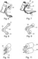
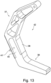
- the back support 1 shown has a bracket 2 which can be attached by means of a manually operable screw 3 to a saddle of a bicycle (not shown) or to another pedal-driven device.
- a system part 4 is used to support a person operating the device (not shown). This system part is articulated by means of a locking screw 5 and can be fixed in different positions on the holder 2 .
- a bracket 7 with an I-shaped cross-section serves as the connection between a contact body 6 and the holder 2 .
- the contact body 6 can simply be plugged onto the contact body axis 9 .
- the plant body 6 can with the bracket 7 along the back of a cyclist can be moved or set and fixed in a position that suits the cyclist individually (variator).
- a roller 8 and 10 is arranged on both sides of the bracket 7 and is firmly connected to the contact body axis 9 so that the contact body axis 9 as a shaft 11 together with the contact bodies 8 and 10 can be rotated relative to the bracket 7 .
- the bracket 7 has a first bore 12 for the shaft 11 for this purpose.
- the contact body axis 8 is arranged parallel to the bracket axis 14 .
- bracket 20 is L-shaped in section in order to hold respective contact bodies 23, 24 in bores 21 and 22 at spaced ends.
- the bracket 20 is held on the holder 2 by means of a locking screw 5 with the bore 25 in between.
- the contact bodies 23, 24 are designed as rollers 26, 27, which are attached to a contact body axis 28, 29.
- the bores 21, 22 and 25 of the bracket 20 are provided for a bracket axis 30 and two axes 28, 29 of the contact body.
- the contact parts 23 and 24 are secured with a threaded hole in the shaft 11 by a washer and screw so that during the movement of the driver in the lateral direction (Z-direction) the contact parts cannot fall off to the side in the event of strong pressure. These discs are in the Figures 6 and 7 good to see.
- the 11 shows the system parts 23 and 24 and the shaft 11, in which the end face is the threaded hole to attach a screw there with a safety washer.
- the figure 12 shows how both balls 31, 32 and rollers 26, 27 can be used on plant body axes.
- the bracket 2 has various struts 33, 34 (numbered only as an example) with which the bracket 2 is constructed as a framework.
- a drinking bottle holder 35 that accommodates a drinking bottle 36 is fastened to this holder 2 .
- Bracket shown is divisible.
- the holder 42 has a first part 37 with a sleeve 38 and a second part 39 with a pin 40, the pin 40 being insertable into the sleeve 38 in order to connect the first part 37 and the second part 39 to one another.
- a locking device 41 is only indicated as a small pin which extends transversely through the sleeve 38 and the spigot 40 to prevent the second part 39 from being pulled off the first part 37 .
Landscapes
- Engineering & Computer Science (AREA)
- Mechanical Engineering (AREA)
- Pivots And Pivotal Connections (AREA)
- Chair Legs, Seat Parts, And Backrests (AREA)
- Chairs Characterized By Structure (AREA)
- Seats For Vehicles (AREA)
Applications Claiming Priority (2)
| Application Number | Priority Date | Filing Date | Title |
|---|---|---|---|
| DE102019007411.4A DE102019007411A1 (de) | 2019-10-24 | 2019-10-24 | Rückenstütze |
| PCT/DE2020/000255 WO2021078317A1 (de) | 2019-10-24 | 2020-10-23 | Rückenstütze für mit einer pedale angetriebene geräte |
Publications (2)
| Publication Number | Publication Date |
|---|---|
| EP3972891A1 EP3972891A1 (de) | 2022-03-30 |
| EP3972891B1 true EP3972891B1 (de) | 2023-05-24 |
Family
ID=73789773
Family Applications (1)
| Application Number | Title | Priority Date | Filing Date |
|---|---|---|---|
| EP20821112.8A Active EP3972891B1 (de) | 2019-10-24 | 2020-10-23 | Rückenstütze für mit einer pedale angetriebene geräte |
Country Status (8)
| Country | Link |
|---|---|
| US (1) | US11912365B2 (pl) |
| EP (1) | EP3972891B1 (pl) |
| JP (1) | JP2022553691A (pl) |
| AU (1) | AU2020370525A1 (pl) |
| DE (2) | DE102019007411A1 (pl) |
| ES (1) | ES2954440T3 (pl) |
| PL (1) | PL3972891T3 (pl) |
| WO (1) | WO2021078317A1 (pl) |
Families Citing this family (2)
| Publication number | Priority date | Publication date | Assignee | Title |
|---|---|---|---|---|
| USD1014401S1 (en) * | 2021-09-09 | 2024-02-13 | Luis Jesus Lopez | Bottle or other accessories mount |
| CN216887018U (zh) * | 2022-03-03 | 2022-07-05 | 北京优贝百祺科技股份有限公司 | 一种带有水壶的鞍座 |
Family Cites Families (12)
| Publication number | Priority date | Publication date | Assignee | Title |
|---|---|---|---|---|
| US553722A (en) * | 1896-01-28 | prall | ||
| GB191112532A (en) * | 1911-05-24 | 1911-10-26 | Thomas Eltringham Wi Henderson | An Adjustable Self Acting Back Rest for Motor and other Cycles. |
| US4313639A (en) * | 1979-05-29 | 1982-02-02 | Ware Manufacturing, Incorporated | Motorcycle backrest |
| JPH0431681U (pl) * | 1990-07-12 | 1992-03-13 | ||
| DE4239548A1 (en) * | 1992-11-25 | 1993-04-15 | Juergen Stiewe | Office or work chair - has brackets, rollers, and circular tracks to allow adjustable tilt for seat and backrest |
| US6206399B1 (en) * | 1996-03-15 | 2001-03-27 | Francis X. Schnitzenbaumer | Bicycle body support and brace |
| US5887943A (en) * | 1996-05-20 | 1999-03-30 | Lee; Christopher J. | Bicycle seat thrust support |
| US8011725B2 (en) * | 2009-05-22 | 2011-09-06 | Kenneth Scott Andrews | Bicycle rider seat brace |
| KR20100133054A (ko) * | 2009-06-11 | 2010-12-21 | 이정우 | 자전거 안장의 엉덩이 밀림 방지 판 |
| US8382139B2 (en) * | 2011-05-02 | 2013-02-26 | Damian Schexnayder | Torsion seat-handle to facilitate learning bicycle riding |
| ES2996532T3 (en) * | 2017-11-04 | 2025-02-12 | B&T Innotec Germany Gmbh | Backrest having a holder, saddle having a backrest, and device having a saddle |
| DE202018102821U1 (de) * | 2018-05-21 | 2018-06-08 | Chia-Jung Chang | Verstellbare Rückenlehne für Kraftfahrzeuge |
-
2019
- 2019-10-24 DE DE102019007411.4A patent/DE102019007411A1/de not_active Withdrawn
-
2020
- 2020-10-23 US US17/770,224 patent/US11912365B2/en active Active
- 2020-10-23 AU AU2020370525A patent/AU2020370525A1/en not_active Abandoned
- 2020-10-23 WO PCT/DE2020/000255 patent/WO2021078317A1/de not_active Ceased
- 2020-10-23 JP JP2022523270A patent/JP2022553691A/ja active Pending
- 2020-10-23 EP EP20821112.8A patent/EP3972891B1/de active Active
- 2020-10-23 PL PL20821112.8T patent/PL3972891T3/pl unknown
- 2020-10-23 DE DE112020005116.1T patent/DE112020005116A5/de active Pending
- 2020-10-23 ES ES20821112T patent/ES2954440T3/es active Active
Also Published As
| Publication number | Publication date |
|---|---|
| US11912365B2 (en) | 2024-02-27 |
| JP2022553691A (ja) | 2022-12-26 |
| ES2954440T3 (es) | 2023-11-22 |
| AU2020370525A1 (en) | 2022-05-19 |
| DE102019007411A1 (de) | 2021-04-29 |
| US20220396327A1 (en) | 2022-12-15 |
| WO2021078317A1 (de) | 2021-04-29 |
| PL3972891T3 (pl) | 2023-10-09 |
| DE112020005116A5 (de) | 2022-07-21 |
| EP3972891A1 (de) | 2022-03-30 |
Similar Documents
| Publication | Publication Date | Title |
|---|---|---|
| EP0734943B1 (de) | Fahrradsitz | |
| DE19943155B4 (de) | Zimmerfahrrad für körperliche Übungen | |
| DE20119292U1 (de) | Dreirad | |
| DE2742719A1 (de) | Trimmfahrrad | |
| DE3132661A1 (de) | Rollschuh | |
| DE202012103125U1 (de) | Fitnessfahrrad für die Freizeit | |
| DE20101815U1 (de) | Roller-Übungsgerät-Kombination | |
| EP3972891B1 (de) | Rückenstütze für mit einer pedale angetriebene geräte | |
| DE20013417U1 (de) | Trainingsgerät mit einem Vorwärts-/Rückwärtsrichtung einstellbaren Sitz | |
| EP3860730B1 (de) | Balance-untersatz für ruderergometer | |
| DE19612632C2 (de) | Trainingsgerät | |
| DE29709387U1 (de) | Vielzweck-Übungsgerät | |
| DE102020127318A1 (de) | Neuartiges Fitnessgerät und zugehörige Gewichtsverstellungsvorrichtung | |
| DE102018006511B4 (de) | Dynamisches Rückenelement für einen Rollstuhl, einen mit diesem Rückenelement ausgestatteten Rollstuhl, eine Anordnung eines Rückenelementes in einem Rollstuhl und die Verwendung eines modifizierten Dämpfelementes zur Bildung des dynamischen Rückenelementes | |
| DE102004048424B4 (de) | Sattelanordnung für eine pedalgetriebene Vorrichtung | |
| DE102009039503A1 (de) | Sattel für Fahrräder, Fitnessgeräte oder dgl. | |
| EP1123859A2 (de) | Sattelträger | |
| AT389641B (de) | Gymnastikgeraet zum staerken der armmuskeln | |
| DE10114121A1 (de) | Vorrichtung für die Sitzflächenanpassung von Fortbewegungsmitteln mit Pedalantrieb | |
| AT392578B (de) | Lehnsessel | |
| EP3684678B1 (de) | Sattelbefestigungseinrichtung | |
| DE202015100142U1 (de) | Fahrradtrainer mit einer Haltebefestigung für ein Fahrradrad | |
| DE102019128945B4 (de) | Vorrichtung zum einstellen des sattelwinkels für ein fahrrad | |
| DE82465C (pl) | ||
| DE29907506U1 (de) | Liegefahrrad |
Legal Events
| Date | Code | Title | Description |
|---|---|---|---|
| STAA | Information on the status of an ep patent application or granted ep patent |
Free format text: STATUS: UNKNOWN |
|
| STAA | Information on the status of an ep patent application or granted ep patent |
Free format text: STATUS: THE INTERNATIONAL PUBLICATION HAS BEEN MADE |
|
| PUAI | Public reference made under article 153(3) epc to a published international application that has entered the european phase |
Free format text: ORIGINAL CODE: 0009012 |
|
| STAA | Information on the status of an ep patent application or granted ep patent |
Free format text: STATUS: REQUEST FOR EXAMINATION WAS MADE |
|
| 17P | Request for examination filed |
Effective date: 20211222 |
|
| AK | Designated contracting states |
Kind code of ref document: A1 Designated state(s): AL AT BE BG CH CY CZ DE DK EE ES FI FR GB GR HR HU IE IS IT LI LT LU LV MC MK MT NL NO PL PT RO RS SE SI SK SM TR |
|
| GRAP | Despatch of communication of intention to grant a patent |
Free format text: ORIGINAL CODE: EPIDOSNIGR1 |
|
| STAA | Information on the status of an ep patent application or granted ep patent |
Free format text: STATUS: GRANT OF PATENT IS INTENDED |
|
| INTG | Intention to grant announced |
Effective date: 20220729 |
|
| GRAS | Grant fee paid |
Free format text: ORIGINAL CODE: EPIDOSNIGR3 |
|
| GRAJ | Information related to disapproval of communication of intention to grant by the applicant or resumption of examination proceedings by the epo deleted |
Free format text: ORIGINAL CODE: EPIDOSDIGR1 |
|
| GRAL | Information related to payment of fee for publishing/printing deleted |
Free format text: ORIGINAL CODE: EPIDOSDIGR3 |
|
| STAA | Information on the status of an ep patent application or granted ep patent |
Free format text: STATUS: REQUEST FOR EXAMINATION WAS MADE |
|
| GRAP | Despatch of communication of intention to grant a patent |
Free format text: ORIGINAL CODE: EPIDOSNIGR1 |
|
| STAA | Information on the status of an ep patent application or granted ep patent |
Free format text: STATUS: GRANT OF PATENT IS INTENDED |
|
| INTC | Intention to grant announced (deleted) | ||
| DAV | Request for validation of the european patent (deleted) | ||
| DAX | Request for extension of the european patent (deleted) | ||
| INTG | Intention to grant announced |
Effective date: 20221220 |
|
| GRAA | (expected) grant |
Free format text: ORIGINAL CODE: 0009210 |
|
| STAA | Information on the status of an ep patent application or granted ep patent |
Free format text: STATUS: THE PATENT HAS BEEN GRANTED |
|
| RAP1 | Party data changed (applicant data changed or rights of an application transferred) |
Owner name: B&T INNOTEC GERMANY GMBH |
|
| RIN1 | Information on inventor provided before grant (corrected) |
Inventor name: TSCHEINIG, ANDREAS Inventor name: BOGENSCHUETZ, JOSEF |
|
| AK | Designated contracting states |
Kind code of ref document: B1 Designated state(s): AL AT BE BG CH CY CZ DE DK EE ES FI FR GB GR HR HU IE IS IT LI LT LU LV MC MK MT NL NO PL PT RO RS SE SI SK SM TR |
|
| REG | Reference to a national code |
Ref country code: GB Ref legal event code: FG4D Free format text: NOT ENGLISH |
|
| REG | Reference to a national code |
Ref country code: CH Ref legal event code: EP |
|
| REG | Reference to a national code |
Ref country code: DE Ref legal event code: R096 Ref document number: 502020003350 Country of ref document: DE |
|
| REG | Reference to a national code |
Ref country code: AT Ref legal event code: REF Ref document number: 1569353 Country of ref document: AT Kind code of ref document: T Effective date: 20230615 |
|
| REG | Reference to a national code |
Ref country code: IE Ref legal event code: FG4D Free format text: LANGUAGE OF EP DOCUMENT: GERMAN |
|
| REG | Reference to a national code |
Ref country code: NL Ref legal event code: FP |
|
| REG | Reference to a national code |
Ref country code: LT Ref legal event code: MG9D |
|
| PG25 | Lapsed in a contracting state [announced via postgrant information from national office to epo] |
Ref country code: SE Free format text: LAPSE BECAUSE OF FAILURE TO SUBMIT A TRANSLATION OF THE DESCRIPTION OR TO PAY THE FEE WITHIN THE PRESCRIBED TIME-LIMIT Effective date: 20230524 Ref country code: PT Free format text: LAPSE BECAUSE OF FAILURE TO SUBMIT A TRANSLATION OF THE DESCRIPTION OR TO PAY THE FEE WITHIN THE PRESCRIBED TIME-LIMIT Effective date: 20230925 Ref country code: NO Free format text: LAPSE BECAUSE OF FAILURE TO SUBMIT A TRANSLATION OF THE DESCRIPTION OR TO PAY THE FEE WITHIN THE PRESCRIBED TIME-LIMIT Effective date: 20230824 |
|
| REG | Reference to a national code |
Ref country code: ES Ref legal event code: FG2A Ref document number: 2954440 Country of ref document: ES Kind code of ref document: T3 Effective date: 20231122 |
|
| PG25 | Lapsed in a contracting state [announced via postgrant information from national office to epo] |
Ref country code: RS Free format text: LAPSE BECAUSE OF FAILURE TO SUBMIT A TRANSLATION OF THE DESCRIPTION OR TO PAY THE FEE WITHIN THE PRESCRIBED TIME-LIMIT Effective date: 20230524 Ref country code: LV Free format text: LAPSE BECAUSE OF FAILURE TO SUBMIT A TRANSLATION OF THE DESCRIPTION OR TO PAY THE FEE WITHIN THE PRESCRIBED TIME-LIMIT Effective date: 20230524 Ref country code: LT Free format text: LAPSE BECAUSE OF FAILURE TO SUBMIT A TRANSLATION OF THE DESCRIPTION OR TO PAY THE FEE WITHIN THE PRESCRIBED TIME-LIMIT Effective date: 20230524 Ref country code: IS Free format text: LAPSE BECAUSE OF FAILURE TO SUBMIT A TRANSLATION OF THE DESCRIPTION OR TO PAY THE FEE WITHIN THE PRESCRIBED TIME-LIMIT Effective date: 20230924 Ref country code: HR Free format text: LAPSE BECAUSE OF FAILURE TO SUBMIT A TRANSLATION OF THE DESCRIPTION OR TO PAY THE FEE WITHIN THE PRESCRIBED TIME-LIMIT Effective date: 20230524 Ref country code: GR Free format text: LAPSE BECAUSE OF FAILURE TO SUBMIT A TRANSLATION OF THE DESCRIPTION OR TO PAY THE FEE WITHIN THE PRESCRIBED TIME-LIMIT Effective date: 20230825 |
|
| PG25 | Lapsed in a contracting state [announced via postgrant information from national office to epo] |
Ref country code: FI Free format text: LAPSE BECAUSE OF FAILURE TO SUBMIT A TRANSLATION OF THE DESCRIPTION OR TO PAY THE FEE WITHIN THE PRESCRIBED TIME-LIMIT Effective date: 20230524 |
|
| PG25 | Lapsed in a contracting state [announced via postgrant information from national office to epo] |
Ref country code: SK Free format text: LAPSE BECAUSE OF FAILURE TO SUBMIT A TRANSLATION OF THE DESCRIPTION OR TO PAY THE FEE WITHIN THE PRESCRIBED TIME-LIMIT Effective date: 20230524 |
|
| PG25 | Lapsed in a contracting state [announced via postgrant information from national office to epo] |
Ref country code: SM Free format text: LAPSE BECAUSE OF FAILURE TO SUBMIT A TRANSLATION OF THE DESCRIPTION OR TO PAY THE FEE WITHIN THE PRESCRIBED TIME-LIMIT Effective date: 20230524 Ref country code: SK Free format text: LAPSE BECAUSE OF FAILURE TO SUBMIT A TRANSLATION OF THE DESCRIPTION OR TO PAY THE FEE WITHIN THE PRESCRIBED TIME-LIMIT Effective date: 20230524 Ref country code: RO Free format text: LAPSE BECAUSE OF FAILURE TO SUBMIT A TRANSLATION OF THE DESCRIPTION OR TO PAY THE FEE WITHIN THE PRESCRIBED TIME-LIMIT Effective date: 20230524 Ref country code: EE Free format text: LAPSE BECAUSE OF FAILURE TO SUBMIT A TRANSLATION OF THE DESCRIPTION OR TO PAY THE FEE WITHIN THE PRESCRIBED TIME-LIMIT Effective date: 20230524 Ref country code: DK Free format text: LAPSE BECAUSE OF FAILURE TO SUBMIT A TRANSLATION OF THE DESCRIPTION OR TO PAY THE FEE WITHIN THE PRESCRIBED TIME-LIMIT Effective date: 20230524 |
|
| REG | Reference to a national code |
Ref country code: DE Ref legal event code: R097 Ref document number: 502020003350 Country of ref document: DE |
|
| PLBE | No opposition filed within time limit |
Free format text: ORIGINAL CODE: 0009261 |
|
| STAA | Information on the status of an ep patent application or granted ep patent |
Free format text: STATUS: NO OPPOSITION FILED WITHIN TIME LIMIT |
|
| 26N | No opposition filed |
Effective date: 20240227 |
|
| PG25 | Lapsed in a contracting state [announced via postgrant information from national office to epo] |
Ref country code: SI Free format text: LAPSE BECAUSE OF FAILURE TO SUBMIT A TRANSLATION OF THE DESCRIPTION OR TO PAY THE FEE WITHIN THE PRESCRIBED TIME-LIMIT Effective date: 20230524 |
|
| PG25 | Lapsed in a contracting state [announced via postgrant information from national office to epo] |
Ref country code: SI Free format text: LAPSE BECAUSE OF FAILURE TO SUBMIT A TRANSLATION OF THE DESCRIPTION OR TO PAY THE FEE WITHIN THE PRESCRIBED TIME-LIMIT Effective date: 20230524 Ref country code: MC Free format text: LAPSE BECAUSE OF FAILURE TO SUBMIT A TRANSLATION OF THE DESCRIPTION OR TO PAY THE FEE WITHIN THE PRESCRIBED TIME-LIMIT Effective date: 20230524 |
|
| REG | Reference to a national code |
Ref country code: BE Ref legal event code: MM Effective date: 20231031 |
|
| PG25 | Lapsed in a contracting state [announced via postgrant information from national office to epo] |
Ref country code: LU Free format text: LAPSE BECAUSE OF NON-PAYMENT OF DUE FEES Effective date: 20231023 |
|
| PG25 | Lapsed in a contracting state [announced via postgrant information from national office to epo] |
Ref country code: LU Free format text: LAPSE BECAUSE OF NON-PAYMENT OF DUE FEES Effective date: 20231023 |
|
| P01 | Opt-out of the competence of the unified patent court (upc) registered |
Free format text: CASE NUMBER: APP_36454/2024 Effective date: 20240618 |
|
| PG25 | Lapsed in a contracting state [announced via postgrant information from national office to epo] |
Ref country code: BE Free format text: LAPSE BECAUSE OF NON-PAYMENT OF DUE FEES Effective date: 20231031 |
|
| PG25 | Lapsed in a contracting state [announced via postgrant information from national office to epo] |
Ref country code: IE Free format text: LAPSE BECAUSE OF NON-PAYMENT OF DUE FEES Effective date: 20231023 |
|
| PG25 | Lapsed in a contracting state [announced via postgrant information from national office to epo] |
Ref country code: IE Free format text: LAPSE BECAUSE OF NON-PAYMENT OF DUE FEES Effective date: 20231023 |
|
| PG25 | Lapsed in a contracting state [announced via postgrant information from national office to epo] |
Ref country code: BG Free format text: LAPSE BECAUSE OF FAILURE TO SUBMIT A TRANSLATION OF THE DESCRIPTION OR TO PAY THE FEE WITHIN THE PRESCRIBED TIME-LIMIT Effective date: 20230524 |
|
| PG25 | Lapsed in a contracting state [announced via postgrant information from national office to epo] |
Ref country code: BG Free format text: LAPSE BECAUSE OF FAILURE TO SUBMIT A TRANSLATION OF THE DESCRIPTION OR TO PAY THE FEE WITHIN THE PRESCRIBED TIME-LIMIT Effective date: 20230524 |
|
| PG25 | Lapsed in a contracting state [announced via postgrant information from national office to epo] |
Ref country code: CY Free format text: LAPSE BECAUSE OF FAILURE TO SUBMIT A TRANSLATION OF THE DESCRIPTION OR TO PAY THE FEE WITHIN THE PRESCRIBED TIME-LIMIT; INVALID AB INITIO Effective date: 20201023 |
|
| PG25 | Lapsed in a contracting state [announced via postgrant information from national office to epo] |
Ref country code: HU Free format text: LAPSE BECAUSE OF FAILURE TO SUBMIT A TRANSLATION OF THE DESCRIPTION OR TO PAY THE FEE WITHIN THE PRESCRIBED TIME-LIMIT; INVALID AB INITIO Effective date: 20201023 |
|
| PGFP | Annual fee paid to national office [announced via postgrant information from national office to epo] |
Ref country code: PL Payment date: 20250918 Year of fee payment: 6 |
|
| REG | Reference to a national code |
Ref country code: CH Ref legal event code: U11 Free format text: ST27 STATUS EVENT CODE: U-0-0-U10-U11 (AS PROVIDED BY THE NATIONAL OFFICE) Effective date: 20251101 |
|
| PGFP | Annual fee paid to national office [announced via postgrant information from national office to epo] |
Ref country code: NL Payment date: 20251021 Year of fee payment: 6 |
|
| PG25 | Lapsed in a contracting state [announced via postgrant information from national office to epo] |
Ref country code: TR Free format text: LAPSE BECAUSE OF FAILURE TO SUBMIT A TRANSLATION OF THE DESCRIPTION OR TO PAY THE FEE WITHIN THE PRESCRIBED TIME-LIMIT Effective date: 20230524 |
|
| PGFP | Annual fee paid to national office [announced via postgrant information from national office to epo] |
Ref country code: DE Payment date: 20251022 Year of fee payment: 6 |
|
| PGFP | Annual fee paid to national office [announced via postgrant information from national office to epo] |
Ref country code: GB Payment date: 20251022 Year of fee payment: 6 |
|
| PGFP | Annual fee paid to national office [announced via postgrant information from national office to epo] |
Ref country code: AT Payment date: 20251022 Year of fee payment: 6 |
|
| PGFP | Annual fee paid to national office [announced via postgrant information from national office to epo] |
Ref country code: IT Payment date: 20251024 Year of fee payment: 6 |
|
| PGFP | Annual fee paid to national office [announced via postgrant information from national office to epo] |
Ref country code: FR Payment date: 20251030 Year of fee payment: 6 |
|
| PGFP | Annual fee paid to national office [announced via postgrant information from national office to epo] |
Ref country code: CH Payment date: 20251101 Year of fee payment: 6 |
|
| PGFP | Annual fee paid to national office [announced via postgrant information from national office to epo] |
Ref country code: CZ Payment date: 20251015 Year of fee payment: 6 |
|
| PGFP | Annual fee paid to national office [announced via postgrant information from national office to epo] |
Ref country code: ES Payment date: 20251216 Year of fee payment: 6 |