EP3972891B1 - Rückenstütze für mit einer pedale angetriebene geräte - Google Patents
Rückenstütze für mit einer pedale angetriebene geräte Download PDFInfo
- Publication number
- EP3972891B1 EP3972891B1 EP20821112.8A EP20821112A EP3972891B1 EP 3972891 B1 EP3972891 B1 EP 3972891B1 EP 20821112 A EP20821112 A EP 20821112A EP 3972891 B1 EP3972891 B1 EP 3972891B1
- Authority
- EP
- European Patent Office
- Prior art keywords
- bracket
- back support
- support according
- holder
- axis
- Prior art date
- Legal status (The legal status is an assumption and is not a legal conclusion. Google has not performed a legal analysis and makes no representation as to the accuracy of the status listed.)
- Active
Links
Images


Classifications
-
- B—PERFORMING OPERATIONS; TRANSPORTING
- B62—LAND VEHICLES FOR TRAVELLING OTHERWISE THAN ON RAILS
- B62J—CYCLE SADDLES OR SEATS; AUXILIARY DEVICES OR ACCESSORIES SPECIALLY ADAPTED TO CYCLES AND NOT OTHERWISE PROVIDED FOR, e.g. ARTICLE CARRIERS OR CYCLE PROTECTORS
- B62J1/00—Saddles or other seats for cycles; Arrangement thereof; Component parts
- B62J1/28—Other additional equipment, e.g. back-rests for children
-
- B—PERFORMING OPERATIONS; TRANSPORTING
- B62—LAND VEHICLES FOR TRAVELLING OTHERWISE THAN ON RAILS
- B62J—CYCLE SADDLES OR SEATS; AUXILIARY DEVICES OR ACCESSORIES SPECIALLY ADAPTED TO CYCLES AND NOT OTHERWISE PROVIDED FOR, e.g. ARTICLE CARRIERS OR CYCLE PROTECTORS
- B62J11/00—Supporting arrangements specially adapted for fastening specific devices to cycles, e.g. supports for attaching maps
- B62J11/04—Supporting arrangements specially adapted for fastening specific devices to cycles, e.g. supports for attaching maps for bottles
Definitions
- the invention relates to a back support for devices driven by pedals, with a holder for attachment to a device and a contact part arranged thereon for supporting a person operating the device. Furthermore, the invention also relates to a saddle with such a back support and a device, in particular a bicycle with a saddle, with such a back support.
- back supports are not only suitable for bicycles, motorcycles, pedelecs and other two-wheelers or vehicles operated with pedals, but also for sports equipment that is operated in a stationary manner, such as home trainers or fitness equipment.
- a generic back support is from WO 2019/086059 known.
- This known seat post offers a good counter bearing for a person who is pedaling and who can support their back and in particular their lower back area on this back support.
- Such back supports are usually attached to the saddle and/or the seat post.
- the GB 1911/12 532 A relates to a bicycle in which the backrest is resiliently mounted on a vertical strut.
- Backrests with an articulated cushion show the US 6,206,399 B1 and the U.S. 553,722A .
- the invention is based on the object of further developing such a back support.
- Known seat posts have contact bodies such as balls or rollers, which are movably arranged for mounting.
- the entire system part with the system bodies arranged on it is articulated to the bracket. This makes it possible to fix the system part in a specific position relative to the holder or to keep it pivotable.
- a lever arm between the holder and a contact body enables the contact body to be positioned on a curved line around the articulated connection between the contact part and the holder.
- the height of the plant part and in particular of plant bodies can be adjusted individually.
- the system part can be easily removed from the holder if it is not required, for example when driving downhill, or if it should even interfere.
- the contact part has a plurality of contact bodies, each of which is connected in an articulated manner to the holder.
- the system part has a bracket which is arranged in an articulated manner on the holder.
- a bracket of this type can be I-shaped in section in order to connect the bracket and contact body to one another as a lever.
- the contact part has a plurality of contact bodies which are connected to one another via the bracket which is connected in an articulated manner to the holder. It is advantageous here if the bracket is L-shaped in section or is L-shaped. The angle of the L of the legs does not have to be exactly 90°. The legs can also be arranged in a V-shape relative to one another, for example.
- the L-shaped design makes it possible to firmly position the contact bodies at a specific distance from one another.
- the position is determined by the length of the legs and the angle of the legs to each other.
- the bracket can not only be firmly attached to the bracket, but also be rotatably attached to the bracket.
- the contact part can vibrate about an axis of rotation between the contact part and the holder due to the pressure applied by the rider, in order on the one hand to create a corresponding counter-pressure and on the other hand to be able to yield in such a way that the contact body is optimal against the driver's back.
- the contact bodies spaced transversely to the direction of travel and their elastically padded surface also allow a certain adjustment around a vertical axis of rotation if the contact bodies are first particularly loaded on one side and then the contact bodies on the other side of the bicycle.
- the bracket has two legs of different lengths.
- bracket has two legs arranged at a right, acute or obtuse angle, for example of approximately 90°.
- Geometric bodies of different configurations can be used as contact bodies. It is advantageous if the contact body is a sphere. It is advantageous here if the ball is either rotatable about an axis or rotatably mounted in a cage.
- the plant body can also be a roller. It is advantageous here if the roller can be rotated about its central axis.
- At least one contact body is connected to the bracket so that it can rotate about a contact body axis.
- the special design consisting of spherical or cylindrical contact bodies that can be rotated about an axis, a bracket via which the contact bodies are connected to one another and which is articulated to the bracket, with the contact body axis being rotatably connected to the bracket, enables simple and individual adjustment of the Back support to the driver of the pedal-driven device. It forms a counter bearing for the forces acting on the pedals, it fits perfectly against the rider's back and it also acts as a lateral counter bearing to keep the rider, who moves his back to the side when pedaling, on the saddle .
- the round contact bodies prevent a rubbing relative movement between the contact bodies and the driver's back.
- the bracket positions the contact body in particular optimally to the back in the direction of travel. It also enables an adjustment in the direction perpendicular thereto.
- a major advantage of the proposed back support is that it meets the requirements for stability, ergonomics and lightness with simple means, even with dynamic weight shifts when riding.
- At least one contact body can be plugged onto the contact body axis.
- the contact body axis is rotatable as a shaft together with at least one contact body relative to the bracket.
- An exemplary embodiment provides that the bracket is connected to the holder such that it can rotate about a bracket axis.
- the axis of the contact body is arranged parallel to the axis of the bracket.
- a bracket is particularly preferably used which has three parallel bores for the bracket axis and two bearing body axes. This makes it possible to keep all axes movable.
- the contact bodies can be mounted so that they can rotate and, in addition, the bracket can be fastened to the mount so that it can rotate.
- the entire system part with the rotatable system bodies can thus rotate about an axis relative to the holder while driving. This means that the system part automatically positions itself optimally.
- the holder of the back support can be made particularly simple and stable if you have a truss.
- a diverse use of the back support opens up when the bracket is divisible.
- the upper part can be omitted to save weight, while the lower part remains attached to the seat post.
- other parts such as a luggage rack, a water bottle, a child seat, etc. can also be easily attached to the lower part.
- the holder can be split in the lower third when installed. As a result, the weight can be significantly reduced by removing the upper part and the dividing area is then easily accessible behind the saddle. It is therefore also proposed that the holder can be divided approximately at the height of the saddle.
- a preferred embodiment provides that the holder has a first part with a sleeve and a second part with a pin, the pin being able to be inserted into the sleeve in order to connect the first part and the second part to one another.
- the holder can have a locking device in order to securely connect parts that are plugged into one another.
- This locking device can have a lever, a screw, a button or a locking button that must be actuated in order to release the parts of the holder.
- a lock can also be arranged at this connection, which prevents unauthorized sharing of the holder.
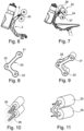
- the back support 1 shown has a bracket 2 which can be attached by means of a manually operable screw 3 to a saddle of a bicycle (not shown) or to another pedal-driven device.
- a system part 4 is used to support a person operating the device (not shown). This system part is articulated by means of a locking screw 5 and can be fixed in different positions on the holder 2 .
- a bracket 7 with an I-shaped cross-section serves as the connection between a contact body 6 and the holder 2 .
- the contact body 6 can simply be plugged onto the contact body axis 9 .
- the plant body 6 can with the bracket 7 along the back of a cyclist can be moved or set and fixed in a position that suits the cyclist individually (variator).
- a roller 8 and 10 is arranged on both sides of the bracket 7 and is firmly connected to the contact body axis 9 so that the contact body axis 9 as a shaft 11 together with the contact bodies 8 and 10 can be rotated relative to the bracket 7 .
- the bracket 7 has a first bore 12 for the shaft 11 for this purpose.
- the contact body axis 8 is arranged parallel to the bracket axis 14 .
- bracket 20 is L-shaped in section in order to hold respective contact bodies 23, 24 in bores 21 and 22 at spaced ends.
- the bracket 20 is held on the holder 2 by means of a locking screw 5 with the bore 25 in between.
- the contact bodies 23, 24 are designed as rollers 26, 27, which are attached to a contact body axis 28, 29.
- the bores 21, 22 and 25 of the bracket 20 are provided for a bracket axis 30 and two axes 28, 29 of the contact body.
- the contact parts 23 and 24 are secured with a threaded hole in the shaft 11 by a washer and screw so that during the movement of the driver in the lateral direction (Z-direction) the contact parts cannot fall off to the side in the event of strong pressure. These discs are in the Figures 6 and 7 good to see.
- the 11 shows the system parts 23 and 24 and the shaft 11, in which the end face is the threaded hole to attach a screw there with a safety washer.
- the figure 12 shows how both balls 31, 32 and rollers 26, 27 can be used on plant body axes.
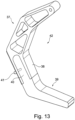
- the bracket 2 has various struts 33, 34 (numbered only as an example) with which the bracket 2 is constructed as a framework.
- a drinking bottle holder 35 that accommodates a drinking bottle 36 is fastened to this holder 2 .
- Bracket shown is divisible.
- the holder 42 has a first part 37 with a sleeve 38 and a second part 39 with a pin 40, the pin 40 being insertable into the sleeve 38 in order to connect the first part 37 and the second part 39 to one another.
- a locking device 41 is only indicated as a small pin which extends transversely through the sleeve 38 and the spigot 40 to prevent the second part 39 from being pulled off the first part 37 .
Landscapes
- Engineering & Computer Science (AREA)
- Mechanical Engineering (AREA)
- Pivots And Pivotal Connections (AREA)
- Chair Legs, Seat Parts, And Backrests (AREA)
- Seats For Vehicles (AREA)
- Chairs Characterized By Structure (AREA)
Description
- Die Erfindung betrifft eine Rückenstütze für mit einer Pedale angetriebene Geräte, mit einer Halterung für eine Befestigung an einem Gerät und einem daran angeordneten Anlageteil zur Abstützung einer das Gerät bedienenden Person. Ferner betrifft die Erfindung auch einen Sattel mit einer derartigen Rückenstütze und ein Gerät, insbesondere ein Fahrrad mit einem Sattel, mit einer derartigen Rückenstütze. Derartige Rückenstützen eignen sich aber nicht nur für Fahrräder, Motorräder, Pedelecs, und andere Zweiräder oder mit einer Pedale betriebene Fahrzeuge, sondern auch für Sportgeräte, die ortsfest betrieben werden, wie Hometrainer oder Fitnessgeräte.
- Eine gattungsgemäße Rückenstütze ist aus der
WO 2019/086059 bekannt. Diese bekannte Sattelstütze bietet ein gutes Gegenlager für eine Person, die in eine Pedale tritt und sich mit dem Rücken und insbesondere mit dem unteren Rückenbereich an dieser Rückenstütze abstützen kann. Derartige Rückenstützen sind üblicherweise am Sattel und/oder an der Sattelstange befestigt. - Die
GB 1911/12 532 A US 6,206,399 B1 und dieUS 553,722 A . - Der Erfindung liegt die Aufgabe zu Grunde, eine derartige Rückenstütze weiterzuentwickeln.
- Diese Aufgabe wird mit einer Rückenstütze mit den Merkmalen des Patentanspruchs 1 gelöst. Vorteilhafte Weiterbildungen sind Gegenstand der Unteransprüche.
- Bekannte Sattelstützen haben Anlagekörper wie Kugeln oder Walzen, die beweglich zur Halterung angeordnet sind. Es hat sich jedoch herausgestellt, dass es besonders vorteilhaft ist, wenn das gesamte Anlageteil mit den daran angeordneten Anlagekörpern gelenkig mit der Halterung verbunden ist. Dies ermöglicht es, das Anlageteil relativ zur Halterung in einer bestimmten Position zu fixieren oder auch schwenkbar zu halten. Ein Hebelarm zwischen der Halterung und einem Anlagekörper ermöglicht eine Positionierung des Anlagekörpers auf einer Bogenlinie um die gelenkige Verbindung zwischen Anlageteil und Halterung. Dadurch kann die Höhe des Anlageteils und insbesondere von Anlagekörpern individuell eingestellt werden. Außerdem kann das Anlageteil leicht von der Halterung entfernt werden, wenn es beispielsweise beim Bergabfahren nicht benötigt wird oder sogar stören sollte.
- Besonders vorteilhaft ist, dass das Anlageteil mehrere Anlagekörper aufweist, die jeweils gelenkig mit der Halterung verbunden sind.
- Außerdem weist das Anlageteil einen Bügel auf, der gelenkig an der Halterung angeordnet ist. Ein derartiger Bügel kann im Schnitt I-förmig sein, um als Hebel Halterung und Anlagekörper miteinander zu verbinden.
- Erfindungsgemäß weist das Anlageteil mehrere Anlagekörper auf, die über den Bügel miteinander verbunden sind, der gelenkig mit der Halterung verbunden ist. Hierbei ist es vorteilhaft, wenn der Bügel im Schnitt L-förmig ausgebildet ist oder L-Formartig ausgebildet ist. Hierbei muss der Winkel des L der Schenkel nicht genau 90 ° sein. Die Schenkel können beispielsweise auch V-förmig zueinander angeordnet sein.
- Die L-förmige Ausbildung ermöglicht es, die Anlagekörper in einem bestimmten Abstand zueinander fest zu positionieren. Dabei wird die Position durch die Länge der Schenkel und den Winkel der Schenkel zueinander bestimmt. Darüber hinaus kann der Bügel nicht nur fest an der Halterung befestigt werden, sondern auch drehbeweglich an der Halterung befestigt sein. Dies führt dazu, dass das Anlageteil beim Fahrradfahren durch den vom Fahrer aufgebrachten Druck um eine Drehachse zwischen Anlageteil und Halterung schwingen kann, um einerseits einen entsprechenden Gegendruck zu bilden und andererseits auch so nachgeben zu können, dass die Anlagekörper optimal am Rücken des Fahrers anliegen. Die quer zur Fahrtrichtung beabstandet angeordneten Anlagekörper und deren elastisch gepolsterte Oberfläche ermöglichen darüber hinaus auch eine gewisse Anpassung um eine senkrechte Drehachse, wenn beim Fahren die Anlagekörper zunächst auf einer Seite besonders belastet werden und danach die Anlagekörper auf der anderen Seite des Fahrrades.
- Für eine besonders gute ergonomische Anpassung während der Fahrt wird vorgeschlagen, dass der Bügel zwei Schenkel mit unterschiedlicher Länge aufweist.
- Ein einfacher, leichter Aufbau ergibt sich, wenn der Bügel zwei in einem rechten, spitzen oder stumpfen Winkel, beispielsweise von etwa 90 ° angeordnete Schenkel aufweist.
- Als Anlagekörper sind geometrische Körper unterschiedlicher Ausbildungen einsetzbar. Vorteilhaft ist es, wenn der Anlagekörper eine Kugel ist. Hierbei ist es vorteilhaft, wenn die Kugel entweder um eine Achse drehbar oder in einem Käfig drehbar gelagert ist. Der Anlagekörper kann auch eine Walze sein. Hierbei ist es vorteilhaft, wenn die Walze um ihre zentrale Achse drehbar ist.
- Daher wird vorgeschlagen, dass mindestens ein Anlagekörper um eine Anlagekörperachse drehbar mit dem Bügel verbunden ist.
- Die spezielle Ausbildung aus um eine Achse drehbaren kugel- oder walzenförmigen Anlagekörpern, einem Bügel, über den die Anlagekörper miteinander verbunden sind und der gelenkig mit der Halterung verbunden ist, wobei die Anlagekörperachse drehbar mit dem Bügel verbunden ist, ermöglicht eine einfache und individuelle Anpassung der Rückenstütze an den Fahrer des mit einer Pedale angetriebenen Gerätes. Sie bildet ein Gegenlager für die auf die Pedale wirkenden Kräfte, sie legt sich optimal am Rücken des Fahrers an und sie wirkt auch seitlich als Gegenlager, um den Fahrer, der beim in die Pedale treten den Rücken zur Seite bewegt, auf dem Sattel zu halten. Die runden Anlagekörper verhindern eine schleifende Relativbewegung zwischen den Anlagekörpern und dem Rücken des Fahrers. Der Bügel positioniert die Anlagekörper insbesondere in Fahrtrichtung optimal zum Rücken. Dabei ermöglicht er auch eine Anpassung in dazu senkrechter Richtung.
- Da bei Fahrrädern besonders auf das Gewicht geachtet wird, ist ein großer Vorteil der vorgeschlagenen Rückenstütze, dass sie mit einfachen Mitteln auch bei den dynamischen Gewichtsverlagerungen beim Fahren den Anforderungen an Stabilität, Ergonomie und Leichtigkeit gerecht wird.
- Hierbei ist es besonders vorteilhaft, wenn mindestens ein Anlagekörper auf die Anlagekörperachse aufsteckbar ist.
- Weiterhin ist es vorteilhaft, wenn die Anlagekörperachse als Welle zusammen mit mindestens einem Anlagekörper relativ zum Bügel drehbar ist.
- Ein Ausführungsbeispiel sieht vor, dass der Bügel um eine Bügelachse drehbar mit der Halterung verbunden ist.
- Dabei ist es von Vorteil, wenn die Anlagekörperachse parallel zur Bügelachse angeordnet ist.
- Besonders bevorzugt wird ein Bügel eingesetzt, der drei parallele Bohrungen für die Bügelachse und zwei Anlagekörperachsen aufweist. Dies ermöglicht es, alle Achsen beweglich zu halten. Somit können die Anlagekörper drehbeweglich gelagert werden und darüber hinaus kann der Bügel drehbeweglich an der Halterung befestigt sein. Das gesamte Anlageteil mit den drehbaren Anlagekörpern kann sich somit während der Fahrt relativ zur Halterung um eine Achse drehen. Dies führt dazu, dass sich das Anlageteil selbständig optimal positioniert.
- Die Halterung der Rückenstütze kann besonders einfach und stabil hergestellt werden, wenn Sie ein Fachwerk aufweist.
- Eine vielfältige Verwendung der Rückenstütze erschließt sich, wenn die Halterung teilbar ist. Es kann zum Einsparen von Gewicht auf das obere Teil verzichtet werden, während das untere Teil an der Sattelstange befestigt bleibt. Es können aber auch andere Teile wie ein Gepäckträger, eine Wasserflasche ein Kindersitz etc. auf einfache Art und Weise am unteren Teil befestigt werden. Besonders vorteilhaft ist es, wenn die Halterung eingebaut im unteren Drittel teilbar ist. Dadurch kann das Gewicht durch Abnehmen des oberen Teils deutlich reduziert werden und der Teilungsbereich ist dann hinter dem Sattel gut zugänglich. Es wird daher auch vorgeschlagen, dass die Halterung etwa in der Höhe des Sattels teilbar ist.
- Eine bevorzugte Ausführungsform sieht vor dass die Halterung ein erstes Teil mit einer Hülse und ein zweites Teil mit einem Zapfen aufweist, wobei der Zapfen in die Hülse steckbar ist, um erstes Teil und zweites Teil miteinander zu verbinden.
- Außerdem kann die Halterung eine Arretiereinrichtung aufweisen, um ineinander gesteckte Teile sicher miteinander zu verbinden. Diese Arretiereinrichtung kann einen Hebel, eine Verschraubung, einen Knopf oder Rastknopf aufweisen, die betätigt werden müssen, um die Teile der Halterung zu lösen. An dieser Verbindung kann auch ein Schloss angeordnet sein, das ein unbefugtes Teilen der Halterung verhindert.
- Bevorzugte Ausführungsbeispiele sind in der Zeichnung dargestellt und werden im Folgenden näher erläutert.
- Es zeigen
- Figur 1
- eine schematische Darstellung einer Rückenstütze mit nur einem Anlagekörper,
- Figur 2
- eine perspektivische Ansicht der in
Figur 1 gezeigten Rückenstütze, - Figur 3
- einen Schnitt durch einen I-förmigen Bügel,
- Figur 4
- eine perspektivische Ansicht des in
Figur 3 gezeigten Bügels, - Figur 5
- eine perspektivische Ansicht eines als Walze ausgebildeten Anlagekörpers,
- Figur 6
- eine schematische Ansicht einer Rückenstütze mit zwei Anlagekörpern,
- Figur 7
- eine perspektivische Ansicht der in
Figur 6 gezeigten Rückenstütze, - Figur 8
- einen Schnitt durch einen L-förmigen Bügel,
- Figur 9
- eine perspektivische Ansicht des in
Figur 8 gezeigten L-förmigen Bügels, - Figur 10
- eine perspektivische Ansicht von zwei als Walze ausgebildeten Anlagekörpern,
- Figur 11
- die in
Figur 10 gezeigten Anlagekörper mit dem inFigur 9 gezeigten Lförmigen Bügel, - Figur 12
- eine Rückenstütze mit einseitig kugelförmigen Anlagekörpern und auf der anderen Seite Anlagekörpern, die als Walze ausgebildet sind, und
- Figur 13
- eine teilbare Halterung.
- Die in
Figur 1 gezeigte Rückenstütze 1 hat eine Halterung 2, die mittels einer manuell bedienbaren Schraube 3 an einem Sattel eines Fahrrads (nicht gezeigt) oder an einem anderen mittels einer Pedale angetriebenen Gerätes befestigt werden kann. Ein Anlageteil 4 dient der Abstützung einer das Gerät bedienenden Person (nicht gezeigt). Dieses Anlageteil ist mittels einer Feststellschraube 5 gelenkig und in verschiedenen Positionen fixierbar an der Halterung 2 befestigt. - Als Verbindung zwischen einem Anlagekörper 6 und der Halterung 2 dient in diesem Ausführungsbeispiel ein im Schnitt I-förmig ausgebildeter Bügel 7. Der Anlagekörper 6 ist eine Walze 8, die um eine Anlagekörperachse 9 drehbar mit dem Bügel 7 verbunden ist. Hierfür kann der Anlagekörper 6 einfach auf die Anlagekörperachse 9 aufgesteckt werden. Der Anlagekörper 6 kann mit dem Bügel 7 entlang des Rückens eines Fahrradfahrers beweglich sein oder in einer individuell zum Fahrradfahrer passenden Position eingestellt und fixiert werden (Variator).
- In diesem Ausführungsbeispiel ist beidseitig des Bügels 7 jeweils eine Walze 8 und 10 angeordnet, die fest mit der Anlagekörperachse 9 verbunden sind, sodass die Anlagekörperachse 9 als Welle 11 zusammen mit den Anlageköpern 8 und 10 relativ zum Bügel 7 drehbar ist. Hierfür weist der Bügel 7 eine erste Bohrung 12 für die Welle 11 auf. Am anderen Ende des Bügels 7 ist eine Bohrung 13 für eine Bügelachse 14, um die das Anlageteil 4 drehbar mit der Halterung 2 verbunden ist. Dabei ist die Anlagekörperachse 8 parallel zur Bügelachse 14 angeordnet.
- Das in den
Figuren 6 bis 12 gezeigte weitere Ausführungsbeispiel ist im Wesentlichen, wie das in denFiguren 1 bis 5 gezeigte Ausführungsbeispiel aufgebaut. Der Bügel 20 ist jedoch im Schnitt L-förmig ausgebildet, um an beabstandeten Enden in Bohrungen 21 und 22 jeweils Anlagekörper 23, 24 zu halten. Mit der dazwischen liegenden Bohrung 25 wird der Bügel 20 an der Halterung 2 mittels einer Feststellschraube 5 gehalten. - Auch bei diesem Ausführungsbeispiel sind die Anlagekörper 23, 24 als Walzen 26, 27 ausgebildet, die auf eine Anlagekörperachse 28, 29 aufgesteckt sind. Die Bohrungen 21, 22 und 25 des Bügels 20 sind für eine Bügelachse 30 und zwei Anlagekörperachsen 28, 29 vorgesehen. Die Anlageteile 23 und 24 sind mit einer in der Welle 11 angebrachten Bohrung mit Gewinde durch eine Scheibe und Schraube so gesichert, das während der Bewegung des Fahrer in seitlicher Richtung (Z-Richtung) die Anlageteile bei starkem Druck nicht seitlich abfallen können. Diese Scheiben sind in den
Figuren 6 und 7 gut zu sehen. DieFig. 11 zeigt die Anlageteile 23 und 24 und die Welle 11, in der sich stirnseitig die Bohrung mit Gewinde befindet, um dort eine Schraube mit einer Sicherheitsscheibe anzubringen. - Die
Figur 12 zeigt, wie auf Anlagekörperachsen sowohl Kugeln 31, 32 als auch Walzen 26, 27 verwendet werden können. - Die Halterung 2 hat verschiedene Streben 33, 34 (nur exemplarisch beziffert) mit denen die Halterung 2 als Fachwerk aufgebaut ist.
- An dieser Halterung 2 ist im Ausführungsbeispiel eine Trinkflaschenhalterung 35 befestigt, die eine Trinkflasche 36 aufnimmt.
- Die in
Figur 13 gezeigte Halterung ist teilbar. Dafür weist die Halterung 42 ein erstes Teil 37 mit einer Hülse 38 und ein zweites Teil 39 mit einem Zapfen 40 auf, wobei der Zapfen 40 in die Hülse 38 steckbar ist, um erstes Teil 37 und zweites Teil 39 miteinander zu verbinden. Eine Arretiereinrichtung 41 ist nur als kleiner Stift angedeutet, der sich quer durch die Hülse 38 und den Zapfen 40 erstreckt, um zu verhindern, dass das zweite Teil 39 vom ersten Teil 37 abgezogen wird.
Claims (15)
- Rückenstütze (1) für mit einer Pedale angetriebene Geräte mit einer Halterung (2) für eine Befestigung an einem Gerät und einem daran angeordneten Anlageteil (4) zur Abstützung einer das Gerät bedienenden Person, wobei das Anlageteil (4) gelenkig mit der Halterung (2) verbunden ist und mehrere Anlagekörper (6, 23, 24) und einen Bügel (7, 20) aufweist, über den die Anlagekörper (23, 24) miteinander verbunden sind, wobei mindestens ein Anlagekörper (6, 23, 24) eine Kugel (31, 32) oder eine Walze (26, 27) ist und um eine Anlagekörper-Achse (9, 28, 29) drehbar mit dem Bügel (7, 20) verbunden ist, dadurch gekennzeichnet, dass der Bügel gelenkig mit der Halterung (2) verbunden ist.
- Rückenstütze nach Anspruch 1, dadurch gekennzeichnet, dass der Bügel (7) im Schnitt I-förmig ist.
- Rückenstütze nach Anspruch 1 oder 2, dadurch gekennzeichnet, dass der Bügel (20) im Schnitt L-förmig ist.
- Rückenstütze nach Anspruch 3, dadurch gekennzeichnet, dass der Bügel (20) zwei Schenkel mit unterschiedlicher Länge aufweist.
- Rückenstütze nach Anspruch 3 oder 4, dadurch gekennzeichnet, dass der Bügel (20) zwei in einem Winkel von etwa 90 ° angeordnete Schenkel aufweist.
- Rückenstütze nach einem der vorhergehenden Ansprüche, dadurch gekennzeichnet, dass mindestens ein Anlagekörper (6, 23, 24) auf die Anlagekörper-Achse (9, 28, 29) aufsteckbar ist.
- Rückenstütze nach einem der vorhergehenden Ansprüche, dadurch gekennzeichnet, dass die Anlagekörper-Achse (9) als Welle (11) zusammen mit mindestens einem Anlagekörper (6, 23, 24) relativ zum Bügel (7, 20) drehbar ist.
- Rückenstütze nach einem der vorhergehenden Ansprüche, dadurch gekennzeichnet, dass der Bügel (7, 20) um eine Bügel-Achse (14) drehbar mit der Halterung (2) verbunden ist.
- Rückenstütze nach Anspruch 8, dadurch gekennzeichnet, dass die Anlagekörper-Achse (9) parallel zur Bügel-Achse (14) angeordnet ist.
- Rückenstütze nach Anspruch 8 oder 9, dadurch gekennzeichnet, dass der Bügel (7) drei parallele Bohrungen (21, 22, 25) für die Bügelachse (30) und zwei AnlagekörperAchsen (28, 29) aufweist.
- Rückenstütze nach einem der vorhergehenden Ansprüche, dadurch gekennzeichnet, dass die Halterung (2) ein Fachwerk aufweist.
- Rückenstütze nach einem der vorhergehenden Ansprüche, dadurch gekennzeichnet, dass die Halterung (2) ein erstes Teil (37) mit einer Hülse (38) und ein zweites Teil (39) mit einem Zapfen (40) aufweist, wobei der Zapfen (40) in die Hülse (38) steckbar ist, um erstes Teil (37) und zweites Teil (39) miteinander zu verbinden.
- Rückenstütze nach Anspruch 12, dadurch gekennzeichnet, dass die Halterung eine Arretiereinrichtung (41) aufweist, um ineinander gesteckte Teile (37, 39) sicher miteinander zu verbinden.
- Sattel mit einer Rückenstütze nach einem der vorhergehenden Ansprüche.
- Gerät, insbesondere Fahrrad mit einem Sattel, mit einer Rückenstütze nach einem der Ansprüche 1 bis 13.
Applications Claiming Priority (2)
| Application Number | Priority Date | Filing Date | Title |
|---|---|---|---|
| DE102019007411.4A DE102019007411A1 (de) | 2019-10-24 | 2019-10-24 | Rückenstütze |
| PCT/DE2020/000255 WO2021078317A1 (de) | 2019-10-24 | 2020-10-23 | Rückenstütze für mit einer pedale angetriebene geräte |
Publications (2)
| Publication Number | Publication Date |
|---|---|
| EP3972891A1 EP3972891A1 (de) | 2022-03-30 |
| EP3972891B1 true EP3972891B1 (de) | 2023-05-24 |
Family
ID=73789773
Family Applications (1)
| Application Number | Title | Priority Date | Filing Date |
|---|---|---|---|
| EP20821112.8A Active EP3972891B1 (de) | 2019-10-24 | 2020-10-23 | Rückenstütze für mit einer pedale angetriebene geräte |
Country Status (8)
| Country | Link |
|---|---|
| US (1) | US11912365B2 (de) |
| EP (1) | EP3972891B1 (de) |
| JP (1) | JP2022553691A (de) |
| AU (1) | AU2020370525A1 (de) |
| DE (2) | DE102019007411A1 (de) |
| ES (1) | ES2954440T3 (de) |
| PL (1) | PL3972891T3 (de) |
| WO (1) | WO2021078317A1 (de) |
Families Citing this family (2)
| Publication number | Priority date | Publication date | Assignee | Title |
|---|---|---|---|---|
| USD1014401S1 (en) * | 2021-09-09 | 2024-02-13 | Luis Jesus Lopez | Bottle or other accessories mount |
| CN216887018U (zh) * | 2022-03-03 | 2022-07-05 | 北京优贝百祺科技股份有限公司 | 一种带有水壶的鞍座 |
Family Cites Families (12)
| Publication number | Priority date | Publication date | Assignee | Title |
|---|---|---|---|---|
| US553722A (en) * | 1896-01-28 | prall | ||
| GB191112532A (en) * | 1911-05-24 | 1911-10-26 | Thomas Eltringham Wi Henderson | An Adjustable Self Acting Back Rest for Motor and other Cycles. |
| US4313639A (en) * | 1979-05-29 | 1982-02-02 | Ware Manufacturing, Incorporated | Motorcycle backrest |
| JPH0431681U (de) * | 1990-07-12 | 1992-03-13 | ||
| DE4239548A1 (en) * | 1992-11-25 | 1993-04-15 | Juergen Stiewe | Office or work chair - has brackets, rollers, and circular tracks to allow adjustable tilt for seat and backrest |
| US6206399B1 (en) * | 1996-03-15 | 2001-03-27 | Francis X. Schnitzenbaumer | Bicycle body support and brace |
| US5887943A (en) * | 1996-05-20 | 1999-03-30 | Lee; Christopher J. | Bicycle seat thrust support |
| US8011725B2 (en) * | 2009-05-22 | 2011-09-06 | Kenneth Scott Andrews | Bicycle rider seat brace |
| KR20100133054A (ko) * | 2009-06-11 | 2010-12-21 | 이정우 | 자전거 안장의 엉덩이 밀림 방지 판 |
| US8382139B2 (en) * | 2011-05-02 | 2013-02-26 | Damian Schexnayder | Torsion seat-handle to facilitate learning bicycle riding |
| EP3573883B1 (de) * | 2017-11-04 | 2024-08-07 | B&T Innotec Germany GmbH | Rückenstütze mit einer halterung, sattel mit einer rückenstütze und gerät mit einem sattel |
| DE202018102821U1 (de) * | 2018-05-21 | 2018-06-08 | Chia-Jung Chang | Verstellbare Rückenlehne für Kraftfahrzeuge |
-
2019
- 2019-10-24 DE DE102019007411.4A patent/DE102019007411A1/de not_active Withdrawn
-
2020
- 2020-10-23 PL PL20821112.8T patent/PL3972891T3/pl unknown
- 2020-10-23 JP JP2022523270A patent/JP2022553691A/ja active Pending
- 2020-10-23 ES ES20821112T patent/ES2954440T3/es active Active
- 2020-10-23 WO PCT/DE2020/000255 patent/WO2021078317A1/de not_active Ceased
- 2020-10-23 US US17/770,224 patent/US11912365B2/en active Active
- 2020-10-23 DE DE112020005116.1T patent/DE112020005116A5/de active Pending
- 2020-10-23 EP EP20821112.8A patent/EP3972891B1/de active Active
- 2020-10-23 AU AU2020370525A patent/AU2020370525A1/en not_active Abandoned
Also Published As
| Publication number | Publication date |
|---|---|
| ES2954440T3 (es) | 2023-11-22 |
| DE112020005116A5 (de) | 2022-07-21 |
| AU2020370525A1 (en) | 2022-05-19 |
| WO2021078317A1 (de) | 2021-04-29 |
| US20220396327A1 (en) | 2022-12-15 |
| DE102019007411A1 (de) | 2021-04-29 |
| US11912365B2 (en) | 2024-02-27 |
| PL3972891T3 (pl) | 2023-10-09 |
| JP2022553691A (ja) | 2022-12-26 |
| EP3972891A1 (de) | 2022-03-30 |
Similar Documents
| Publication | Publication Date | Title |
|---|---|---|
| EP0734943B1 (de) | Fahrradsitz | |
| DE19943155B4 (de) | Zimmerfahrrad für körperliche Übungen | |
| DE20119292U1 (de) | Dreirad | |
| DE2742719A1 (de) | Trimmfahrrad | |
| DE3132661A1 (de) | Rollschuh | |
| DE202012103125U1 (de) | Fitnessfahrrad für die Freizeit | |
| DE20101815U1 (de) | Roller-Übungsgerät-Kombination | |
| EP3972891B1 (de) | Rückenstütze für mit einer pedale angetriebene geräte | |
| DE20013417U1 (de) | Trainingsgerät mit einem Vorwärts-/Rückwärtsrichtung einstellbaren Sitz | |
| EP3860730B1 (de) | Balance-untersatz für ruderergometer | |
| DE19612632C2 (de) | Trainingsgerät | |
| DE29709387U1 (de) | Vielzweck-Übungsgerät | |
| DE102020127318A1 (de) | Neuartiges Fitnessgerät und zugehörige Gewichtsverstellungsvorrichtung | |
| DE102018006511B4 (de) | Dynamisches Rückenelement für einen Rollstuhl, einen mit diesem Rückenelement ausgestatteten Rollstuhl, eine Anordnung eines Rückenelementes in einem Rollstuhl und die Verwendung eines modifizierten Dämpfelementes zur Bildung des dynamischen Rückenelementes | |
| DE102004048424B4 (de) | Sattelanordnung für eine pedalgetriebene Vorrichtung | |
| DE102009039503A1 (de) | Sattel für Fahrräder, Fitnessgeräte oder dgl. | |
| EP1123859A2 (de) | Sattelträger | |
| AT389641B (de) | Gymnastikgeraet zum staerken der armmuskeln | |
| DE10114121A1 (de) | Vorrichtung für die Sitzflächenanpassung von Fortbewegungsmitteln mit Pedalantrieb | |
| AT392578B (de) | Lehnsessel | |
| EP3684678B1 (de) | Sattelbefestigungseinrichtung | |
| DE202015100142U1 (de) | Fahrradtrainer mit einer Haltebefestigung für ein Fahrradrad | |
| DE102019128945B4 (de) | Vorrichtung zum einstellen des sattelwinkels für ein fahrrad | |
| DE82465C (de) | ||
| DE29907506U1 (de) | Liegefahrrad |
Legal Events
| Date | Code | Title | Description |
|---|---|---|---|
| STAA | Information on the status of an ep patent application or granted ep patent |
Free format text: STATUS: UNKNOWN |
|
| STAA | Information on the status of an ep patent application or granted ep patent |
Free format text: STATUS: THE INTERNATIONAL PUBLICATION HAS BEEN MADE |
|
| PUAI | Public reference made under article 153(3) epc to a published international application that has entered the european phase |
Free format text: ORIGINAL CODE: 0009012 |
|
| STAA | Information on the status of an ep patent application or granted ep patent |
Free format text: STATUS: REQUEST FOR EXAMINATION WAS MADE |
|
| 17P | Request for examination filed |
Effective date: 20211222 |
|
| AK | Designated contracting states |
Kind code of ref document: A1 Designated state(s): AL AT BE BG CH CY CZ DE DK EE ES FI FR GB GR HR HU IE IS IT LI LT LU LV MC MK MT NL NO PL PT RO RS SE SI SK SM TR |
|
| GRAP | Despatch of communication of intention to grant a patent |
Free format text: ORIGINAL CODE: EPIDOSNIGR1 |
|
| STAA | Information on the status of an ep patent application or granted ep patent |
Free format text: STATUS: GRANT OF PATENT IS INTENDED |
|
| INTG | Intention to grant announced |
Effective date: 20220729 |
|
| GRAS | Grant fee paid |
Free format text: ORIGINAL CODE: EPIDOSNIGR3 |
|
| GRAJ | Information related to disapproval of communication of intention to grant by the applicant or resumption of examination proceedings by the epo deleted |
Free format text: ORIGINAL CODE: EPIDOSDIGR1 |
|
| GRAL | Information related to payment of fee for publishing/printing deleted |
Free format text: ORIGINAL CODE: EPIDOSDIGR3 |
|
| STAA | Information on the status of an ep patent application or granted ep patent |
Free format text: STATUS: REQUEST FOR EXAMINATION WAS MADE |
|
| GRAP | Despatch of communication of intention to grant a patent |
Free format text: ORIGINAL CODE: EPIDOSNIGR1 |
|
| STAA | Information on the status of an ep patent application or granted ep patent |
Free format text: STATUS: GRANT OF PATENT IS INTENDED |
|
| INTC | Intention to grant announced (deleted) | ||
| DAV | Request for validation of the european patent (deleted) | ||
| DAX | Request for extension of the european patent (deleted) | ||
| INTG | Intention to grant announced |
Effective date: 20221220 |
|
| GRAA | (expected) grant |
Free format text: ORIGINAL CODE: 0009210 |
|
| STAA | Information on the status of an ep patent application or granted ep patent |
Free format text: STATUS: THE PATENT HAS BEEN GRANTED |
|
| RAP1 | Party data changed (applicant data changed or rights of an application transferred) |
Owner name: B&T INNOTEC GERMANY GMBH |
|
| RIN1 | Information on inventor provided before grant (corrected) |
Inventor name: TSCHEINIG, ANDREAS Inventor name: BOGENSCHUETZ, JOSEF |
|
| AK | Designated contracting states |
Kind code of ref document: B1 Designated state(s): AL AT BE BG CH CY CZ DE DK EE ES FI FR GB GR HR HU IE IS IT LI LT LU LV MC MK MT NL NO PL PT RO RS SE SI SK SM TR |
|
| REG | Reference to a national code |
Ref country code: GB Ref legal event code: FG4D Free format text: NOT ENGLISH |
|
| REG | Reference to a national code |
Ref country code: CH Ref legal event code: EP |
|
| REG | Reference to a national code |
Ref country code: DE Ref legal event code: R096 Ref document number: 502020003350 Country of ref document: DE |
|
| REG | Reference to a national code |
Ref country code: AT Ref legal event code: REF Ref document number: 1569353 Country of ref document: AT Kind code of ref document: T Effective date: 20230615 |
|
| REG | Reference to a national code |
Ref country code: IE Ref legal event code: FG4D Free format text: LANGUAGE OF EP DOCUMENT: GERMAN |
|
| REG | Reference to a national code |
Ref country code: NL Ref legal event code: FP |
|
| REG | Reference to a national code |
Ref country code: LT Ref legal event code: MG9D |
|
| PG25 | Lapsed in a contracting state [announced via postgrant information from national office to epo] |
Ref country code: SE Free format text: LAPSE BECAUSE OF FAILURE TO SUBMIT A TRANSLATION OF THE DESCRIPTION OR TO PAY THE FEE WITHIN THE PRESCRIBED TIME-LIMIT Effective date: 20230524 Ref country code: PT Free format text: LAPSE BECAUSE OF FAILURE TO SUBMIT A TRANSLATION OF THE DESCRIPTION OR TO PAY THE FEE WITHIN THE PRESCRIBED TIME-LIMIT Effective date: 20230925 Ref country code: NO Free format text: LAPSE BECAUSE OF FAILURE TO SUBMIT A TRANSLATION OF THE DESCRIPTION OR TO PAY THE FEE WITHIN THE PRESCRIBED TIME-LIMIT Effective date: 20230824 |
|
| REG | Reference to a national code |
Ref country code: ES Ref legal event code: FG2A Ref document number: 2954440 Country of ref document: ES Kind code of ref document: T3 Effective date: 20231122 |
|
| PG25 | Lapsed in a contracting state [announced via postgrant information from national office to epo] |
Ref country code: RS Free format text: LAPSE BECAUSE OF FAILURE TO SUBMIT A TRANSLATION OF THE DESCRIPTION OR TO PAY THE FEE WITHIN THE PRESCRIBED TIME-LIMIT Effective date: 20230524 Ref country code: LV Free format text: LAPSE BECAUSE OF FAILURE TO SUBMIT A TRANSLATION OF THE DESCRIPTION OR TO PAY THE FEE WITHIN THE PRESCRIBED TIME-LIMIT Effective date: 20230524 Ref country code: LT Free format text: LAPSE BECAUSE OF FAILURE TO SUBMIT A TRANSLATION OF THE DESCRIPTION OR TO PAY THE FEE WITHIN THE PRESCRIBED TIME-LIMIT Effective date: 20230524 Ref country code: IS Free format text: LAPSE BECAUSE OF FAILURE TO SUBMIT A TRANSLATION OF THE DESCRIPTION OR TO PAY THE FEE WITHIN THE PRESCRIBED TIME-LIMIT Effective date: 20230924 Ref country code: HR Free format text: LAPSE BECAUSE OF FAILURE TO SUBMIT A TRANSLATION OF THE DESCRIPTION OR TO PAY THE FEE WITHIN THE PRESCRIBED TIME-LIMIT Effective date: 20230524 Ref country code: GR Free format text: LAPSE BECAUSE OF FAILURE TO SUBMIT A TRANSLATION OF THE DESCRIPTION OR TO PAY THE FEE WITHIN THE PRESCRIBED TIME-LIMIT Effective date: 20230825 |
|
| PG25 | Lapsed in a contracting state [announced via postgrant information from national office to epo] |
Ref country code: FI Free format text: LAPSE BECAUSE OF FAILURE TO SUBMIT A TRANSLATION OF THE DESCRIPTION OR TO PAY THE FEE WITHIN THE PRESCRIBED TIME-LIMIT Effective date: 20230524 |
|
| PG25 | Lapsed in a contracting state [announced via postgrant information from national office to epo] |
Ref country code: SK Free format text: LAPSE BECAUSE OF FAILURE TO SUBMIT A TRANSLATION OF THE DESCRIPTION OR TO PAY THE FEE WITHIN THE PRESCRIBED TIME-LIMIT Effective date: 20230524 |
|
| PG25 | Lapsed in a contracting state [announced via postgrant information from national office to epo] |
Ref country code: SM Free format text: LAPSE BECAUSE OF FAILURE TO SUBMIT A TRANSLATION OF THE DESCRIPTION OR TO PAY THE FEE WITHIN THE PRESCRIBED TIME-LIMIT Effective date: 20230524 Ref country code: SK Free format text: LAPSE BECAUSE OF FAILURE TO SUBMIT A TRANSLATION OF THE DESCRIPTION OR TO PAY THE FEE WITHIN THE PRESCRIBED TIME-LIMIT Effective date: 20230524 Ref country code: RO Free format text: LAPSE BECAUSE OF FAILURE TO SUBMIT A TRANSLATION OF THE DESCRIPTION OR TO PAY THE FEE WITHIN THE PRESCRIBED TIME-LIMIT Effective date: 20230524 Ref country code: EE Free format text: LAPSE BECAUSE OF FAILURE TO SUBMIT A TRANSLATION OF THE DESCRIPTION OR TO PAY THE FEE WITHIN THE PRESCRIBED TIME-LIMIT Effective date: 20230524 Ref country code: DK Free format text: LAPSE BECAUSE OF FAILURE TO SUBMIT A TRANSLATION OF THE DESCRIPTION OR TO PAY THE FEE WITHIN THE PRESCRIBED TIME-LIMIT Effective date: 20230524 |
|
| REG | Reference to a national code |
Ref country code: DE Ref legal event code: R097 Ref document number: 502020003350 Country of ref document: DE |
|
| PLBE | No opposition filed within time limit |
Free format text: ORIGINAL CODE: 0009261 |
|
| STAA | Information on the status of an ep patent application or granted ep patent |
Free format text: STATUS: NO OPPOSITION FILED WITHIN TIME LIMIT |
|
| 26N | No opposition filed |
Effective date: 20240227 |
|
| PG25 | Lapsed in a contracting state [announced via postgrant information from national office to epo] |
Ref country code: SI Free format text: LAPSE BECAUSE OF FAILURE TO SUBMIT A TRANSLATION OF THE DESCRIPTION OR TO PAY THE FEE WITHIN THE PRESCRIBED TIME-LIMIT Effective date: 20230524 |
|
| PG25 | Lapsed in a contracting state [announced via postgrant information from national office to epo] |
Ref country code: SI Free format text: LAPSE BECAUSE OF FAILURE TO SUBMIT A TRANSLATION OF THE DESCRIPTION OR TO PAY THE FEE WITHIN THE PRESCRIBED TIME-LIMIT Effective date: 20230524 Ref country code: MC Free format text: LAPSE BECAUSE OF FAILURE TO SUBMIT A TRANSLATION OF THE DESCRIPTION OR TO PAY THE FEE WITHIN THE PRESCRIBED TIME-LIMIT Effective date: 20230524 |
|
| REG | Reference to a national code |
Ref country code: BE Ref legal event code: MM Effective date: 20231031 |
|
| PG25 | Lapsed in a contracting state [announced via postgrant information from national office to epo] |
Ref country code: LU Free format text: LAPSE BECAUSE OF NON-PAYMENT OF DUE FEES Effective date: 20231023 |
|
| PG25 | Lapsed in a contracting state [announced via postgrant information from national office to epo] |
Ref country code: LU Free format text: LAPSE BECAUSE OF NON-PAYMENT OF DUE FEES Effective date: 20231023 |
|
| P01 | Opt-out of the competence of the unified patent court (upc) registered |
Free format text: CASE NUMBER: APP_36454/2024 Effective date: 20240618 |
|
| PG25 | Lapsed in a contracting state [announced via postgrant information from national office to epo] |
Ref country code: BE Free format text: LAPSE BECAUSE OF NON-PAYMENT OF DUE FEES Effective date: 20231031 |
|
| PG25 | Lapsed in a contracting state [announced via postgrant information from national office to epo] |
Ref country code: IE Free format text: LAPSE BECAUSE OF NON-PAYMENT OF DUE FEES Effective date: 20231023 |
|
| PG25 | Lapsed in a contracting state [announced via postgrant information from national office to epo] |
Ref country code: IE Free format text: LAPSE BECAUSE OF NON-PAYMENT OF DUE FEES Effective date: 20231023 |
|
| PG25 | Lapsed in a contracting state [announced via postgrant information from national office to epo] |
Ref country code: BG Free format text: LAPSE BECAUSE OF FAILURE TO SUBMIT A TRANSLATION OF THE DESCRIPTION OR TO PAY THE FEE WITHIN THE PRESCRIBED TIME-LIMIT Effective date: 20230524 |
|
| PG25 | Lapsed in a contracting state [announced via postgrant information from national office to epo] |
Ref country code: BG Free format text: LAPSE BECAUSE OF FAILURE TO SUBMIT A TRANSLATION OF THE DESCRIPTION OR TO PAY THE FEE WITHIN THE PRESCRIBED TIME-LIMIT Effective date: 20230524 |
|
| PG25 | Lapsed in a contracting state [announced via postgrant information from national office to epo] |
Ref country code: CY Free format text: LAPSE BECAUSE OF FAILURE TO SUBMIT A TRANSLATION OF THE DESCRIPTION OR TO PAY THE FEE WITHIN THE PRESCRIBED TIME-LIMIT; INVALID AB INITIO Effective date: 20201023 |
|
| PG25 | Lapsed in a contracting state [announced via postgrant information from national office to epo] |
Ref country code: HU Free format text: LAPSE BECAUSE OF FAILURE TO SUBMIT A TRANSLATION OF THE DESCRIPTION OR TO PAY THE FEE WITHIN THE PRESCRIBED TIME-LIMIT; INVALID AB INITIO Effective date: 20201023 |
|
| PGFP | Annual fee paid to national office [announced via postgrant information from national office to epo] |
Ref country code: PL Payment date: 20250918 Year of fee payment: 6 |
|
| REG | Reference to a national code |
Ref country code: CH Ref legal event code: U11 Free format text: ST27 STATUS EVENT CODE: U-0-0-U10-U11 (AS PROVIDED BY THE NATIONAL OFFICE) Effective date: 20251101 |
|
| PGFP | Annual fee paid to national office [announced via postgrant information from national office to epo] |
Ref country code: NL Payment date: 20251021 Year of fee payment: 6 |
|
| PG25 | Lapsed in a contracting state [announced via postgrant information from national office to epo] |
Ref country code: TR Free format text: LAPSE BECAUSE OF FAILURE TO SUBMIT A TRANSLATION OF THE DESCRIPTION OR TO PAY THE FEE WITHIN THE PRESCRIBED TIME-LIMIT Effective date: 20230524 |
|
| PGFP | Annual fee paid to national office [announced via postgrant information from national office to epo] |
Ref country code: DE Payment date: 20251022 Year of fee payment: 6 |
|
| PGFP | Annual fee paid to national office [announced via postgrant information from national office to epo] |
Ref country code: GB Payment date: 20251022 Year of fee payment: 6 |
|
| PGFP | Annual fee paid to national office [announced via postgrant information from national office to epo] |
Ref country code: AT Payment date: 20251022 Year of fee payment: 6 |
|
| PGFP | Annual fee paid to national office [announced via postgrant information from national office to epo] |
Ref country code: IT Payment date: 20251024 Year of fee payment: 6 |
|
| PGFP | Annual fee paid to national office [announced via postgrant information from national office to epo] |
Ref country code: FR Payment date: 20251030 Year of fee payment: 6 |
|
| PGFP | Annual fee paid to national office [announced via postgrant information from national office to epo] |
Ref country code: CH Payment date: 20251101 Year of fee payment: 6 |
|
| PGFP | Annual fee paid to national office [announced via postgrant information from national office to epo] |
Ref country code: CZ Payment date: 20251015 Year of fee payment: 6 |
|
| PGFP | Annual fee paid to national office [announced via postgrant information from national office to epo] |
Ref country code: ES Payment date: 20251216 Year of fee payment: 6 |