EP3972527B1 - Prothetische zahnimplantatschraube, anziehwerkzeug und kupplungssystem zwischen den beiden - Google Patents
Prothetische zahnimplantatschraube, anziehwerkzeug und kupplungssystem zwischen den beiden Download PDFInfo
- Publication number
- EP3972527B1 EP3972527B1 EP20739935.3A EP20739935A EP3972527B1 EP 3972527 B1 EP3972527 B1 EP 3972527B1 EP 20739935 A EP20739935 A EP 20739935A EP 3972527 B1 EP3972527 B1 EP 3972527B1
- Authority
- EP
- European Patent Office
- Prior art keywords
- screw
- circumference
- diameter
- screwdriver
- tip
- Prior art date
- Legal status (The legal status is an assumption and is not a legal conclusion. Google has not performed a legal analysis and makes no representation as to the accuracy of the status listed.)
- Active
Links
Images










Classifications
-
- A—HUMAN NECESSITIES
- A61—MEDICAL OR VETERINARY SCIENCE; HYGIENE
- A61C—DENTISTRY; APPARATUS OR METHODS FOR ORAL OR DENTAL HYGIENE
- A61C8/00—Means to be fixed to the jaw-bone for consolidating natural teeth or for fixing dental prostheses thereon; Dental implants; Implanting tools
- A61C8/0048—Connecting the upper structure to the implant, e.g. bridging bars
- A61C8/005—Connecting devices for joining an upper structure with an implant member, e.g. spacers
-
- A—HUMAN NECESSITIES
- A61—MEDICAL OR VETERINARY SCIENCE; HYGIENE
- A61C—DENTISTRY; APPARATUS OR METHODS FOR ORAL OR DENTAL HYGIENE
- A61C8/00—Means to be fixed to the jaw-bone for consolidating natural teeth or for fixing dental prostheses thereon; Dental implants; Implanting tools
- A61C8/0048—Connecting the upper structure to the implant, e.g. bridging bars
- A61C8/005—Connecting devices for joining an upper structure with an implant member, e.g. spacers
- A61C8/0068—Connecting devices for joining an upper structure with an implant member, e.g. spacers with an additional screw
-
- A—HUMAN NECESSITIES
- A61—MEDICAL OR VETERINARY SCIENCE; HYGIENE
- A61C—DENTISTRY; APPARATUS OR METHODS FOR ORAL OR DENTAL HYGIENE
- A61C8/00—Means to be fixed to the jaw-bone for consolidating natural teeth or for fixing dental prostheses thereon; Dental implants; Implanting tools
- A61C8/0089—Implanting tools or instruments
-
- B—PERFORMING OPERATIONS; TRANSPORTING
- B25—HAND TOOLS; PORTABLE POWER-DRIVEN TOOLS; MANIPULATORS
- B25B—TOOLS OR BENCH DEVICES NOT OTHERWISE PROVIDED FOR, FOR FASTENING, CONNECTING, DISENGAGING, OR HOLDING
- B25B15/00—Screwdrivers
- B25B15/001—Screwdrivers characterised by material or shape of the tool bit
- B25B15/004—Screwdrivers characterised by material or shape of the tool bit characterised by cross-section
- B25B15/005—Screwdrivers characterised by material or shape of the tool bit characterised by cross-section with cross- or star-shaped cross-section
-
- B—PERFORMING OPERATIONS; TRANSPORTING
- B25—HAND TOOLS; PORTABLE POWER-DRIVEN TOOLS; MANIPULATORS
- B25B—TOOLS OR BENCH DEVICES NOT OTHERWISE PROVIDED FOR, FOR FASTENING, CONNECTING, DISENGAGING, OR HOLDING
- B25B23/00—Details of, or accessories for, spanners, wrenches, screwdrivers
- B25B23/0007—Connections or joints between tool parts
- B25B23/0028—Angular adjustment means between tool head and handle
Definitions
- the present invention dental prosthetic screw implant, tightening tool and coupling system, firstly relates to a screw for retaining and fixing a dental element in a dental implant, said dental element being able to be any component that preferably aims to support a dental structure or dental prosthesis, preferably machined or laser sintered or laser sintered and re-machined or machined by CAD/CAM, and even the structure itself or dental prosthesis. Therefore, different components are used in the manufacture of prostheses on dental implants in human implantology, requiring said components to be retained and fixed to the dental implant by means of screws on the implant. Moreover, the invention relates to a screwdriver or tightening tool compatible with said dental screw and a tightening or coupling system formed by the two.
- the present invention pertaining to the dental prosthetic sector aims to extend the angle of screwing of a dental component or structure to a dental implant by means of a screw, providing advantages by improving the safety of the screwing system of the CAD/CAM machined or sintered structure, or dynamic pillar, by avoiding a greater number of problems, increasing the durability of the components, increasing the number of solutions to solve aesthetic and functional problems, decreasing the probability of the tool disengaging from the screw head during use, increasing the flexibility of use and maintaining the cost with respect to the screws and screwdrivers used in the state of the art.
- Adjusting the angulation enables a tightening torque to be applied which ensures the retention and fixation of the screw and the implant within a specific range of inclination.
- the screw is used to fix and retain a dental structure or dental prosthesis to the dental implant, either directly or indirectly through intermediate components such as interfaces or attachments.
- the screw can be used to retain different components by screwing them into dental models, that is, to screw away from the mouth, for example, during moulding in order to manufacture the prosthesis or for teaching purposes.
- fixation devices for joining two dental elements in particular prosthetic screws for dental implants, which have heads with different geometries that cooperate with complementary screwdriver tips for screwing the screw to another element by means of the screw thread.
- no fixing device or screw with a head at one end and a thread at the opposite end that allows its operation by means of a tightening tool or screwdriver is known, such that between the axis of the screwdriver and the axis of the screw, on the head of which the screwdriver tip is inserted, there is an angle greater than 35° and it enables the screw to be retained and fastened with sufficient guarantees.
- screw and tool assemblies which enable a tightening torque of the tool to be applied to the screw with an inclination of up to 35°.
- This screw and tool assembly known in the state of the art comprise five or six lobules, in the shape of the hollow of the screw and the shape of the head of the tool, that allow to reach this inclination.
- prosthetic screws for dental implants are subject to tightening torques and loosening torques on several occasions, which combined with the configuration of the screw head can cause the wear thereof with the consequent risk of either preventing the tightening of the screw or, even worse, preventing the loosening thereof when it is screwed to the implant.
- the present invention proposes a dental prosthetic screw which enables said drawbacks to be overcome, and in particular, which enables the tightening, or loosening, torque to be transmitted between a screwdriver and a screw, necessary when there is no inclination between the two or when the inclination is less than or equal to 35°, greater than 35°, up to 45o and preferably at least 50°, and preventing wear of the screw head due to stripping.
- the present invention is applicable to metal and non-metal dental structures for dental implants made by the CAD/CAM process as well as for dynamic pillar assemblies.
- the structures of the prostheses made by means of a casting process require the dynamic pillar as a base piece to model the structure in wax and then perform the casting by fixing the pillar in its correct position.
- the metal and non-metal structures made by means of a CAD/CAM process do not require the dynamic pillar since the structure is designed by computer and a machine tool mills said structure, using only the screw and screwdriver of the system for the screwing thereof in angulation.
- Prior art document US2008085492A1 refers to a dental implant designed to support a dental prosthesis, like a crown or denture. It has a unique internal cavity with a cylindrical portion and semi-circular channels, which help to securely hold the prosthesis in place. The ratio of the sizes of these features is carefully designed to optimize the stability and longevity of the implant.
- prior art document DE20108605U1 describes a screwdriver bit that has a flat tip and three or more drive webs.
- the flat tip has a sloping edge that leads to the drive webs that have a curved outer area and a shoulder towards the flat tip.
- the outer regions and the flat tip are essentially parts of a spherical surface.
- This design allows the screwdriver bit to tilt and support itself when driving a screw.
- the invention includes a screw head with a drive for inserting the screwdriver bit.
- Said drive has a recess with grooves that form shoulders and vertical wall areas with a peripheral edge formed between the vertical wall area and the bottom of the recess.
- the present invention overcomes the limitations and disadvantages of the screws and screwdrivers or tightening tools of the state of the art by means of constructive modifications that improve the safety of the screwing system of a prosthetic screw for dental implants and a screwdriver complementary to the screw system, enabling screwing at angles even greater than 35 degrees, from 0° to 45o, preferably to at least 50°.
- a greater number of problems with angulation can be corrected in the retention and fastening of elements to the implants: increasing the number of solutions to problems of improper positioning of the implant; increasing the durability and safety of the screw and the screwdriver by having less wear due to a greater contact surface and the better fit and coupling between the two; allowing greater flexibility of the male and female connections, providing a greater number of solutions to solve aesthetic and functional problems; lower probability of the screwdriver or tool losing contact or disengaging from the screw during threading when there is an inclination between the two at the same time that the required tightening, or loosening, torque is transmitted; lower probability of the screw head losing its geometric shape; greater flexibility of use; and same costs in relation to the screws and tool or screwdrivers of the state of the art.
- a first object of the present invention is therefore a fastening device, or screw, according to claim 1, with a thread at one end and a head at the opposite end to receive a tightening tool by said head.
- the dental prosthetic screw for dental implant object of the invention is intended to be screwed into a threaded housing of a dental implant or equivalent element fixed inside a body, usually the jaw of a patient, such that after inserting the threaded end of the screw in the threaded housing of the implant the same is screwed, or unscrewed, with the help of a tool or screwdriver.
- the screw goes through a channel, straight or with a change of inclination, of a dental structure or dental prosthesis to retain and fix it to the implant, such that the screw head located at the end opposite that of the thread and with a diameter larger than said thread enables said dental structure or prosthesis to be fixed to the implant.
- the dental structure has a channel that passes there through with a diameter approximately equal to the diameter of the screw head and at the lower end of the structure it comprises a seating for said screw head, such that it allows the passage of the threaded end but not the head that abuts against the seating in the dental structure, thus enabling said structure to be retained and fixed to the implant after the corresponding tightening of the screw.
- said inclination could be up to 45°, or preferably it could even be up to 50°, between the axis of the screw and the axis of the screwdriver.
- the longitudinal axis of the screw preferably coincides with the longitudinal axis of the implant once the screw is screwed into the implant.
- the screw and complementary tightening tool, object of this invention have a shape for the hollow of the screw and the head of the tool, with exclusively three equidistant lobules in order to overcome the drawbacks of screws and tools in the prior art with five or six lobules. According to the previously mentioned drawbacks:
- the screw head with a diameter larger than the threaded end of the screw, is provided with a longitudinal hollow or housing with inner walls extending a certain distance along the longitudinal axis of the screw.
- the walls of the hollow are preferably parallel to the longitudinal axis of the screw, although they could be slightly inclined with respect thereto, defining a frustoconical hollow or housing, and they extend a certain length inside the head.
- the bottom of the hollow after the wall thereof, has a preferably frustoconical section but it could also be semi-circular or flat.
- Said hollow comprises in a cross section perpendicular to the longitudinal axis:
- the arc is a segment of a circle or circumference with the same radius as the centre of said circle or circumference, therefore, the centre of the arc is the centre of said circle or circumference. This applies too to the embodiments where the second arcs exist, being the centres of said second arcs placed on a fourth circumference.
- each of the second arcs are tangent to said first circumference at one end and tangent to one of the three first arcs at the other end, such that the transition between the central circular opening of the hollow and the lobes is continuous.
- both arcs preferably have a radius with the same dimension, and preferably the same length, although said radius could be smaller than that of said first arcs. In some embodiments these second arcs could even disappear.
- a screwdriver with a head having a transverse cross section with only three projections, preferably complementary to the projections of the hollow of the screw head, with dimensions slightly smaller than those of said hollow in order to be able to be inserted therein, can preferably be inclined at least up to 45°, preferably 50°, with respect to the longitudinal axis of the screw.
- each of the projections of the screwdriver head has a curved profile in its longitudinal cross section which enables the screwdriver head to pivot, and thus incline, with respect to the hollow or housing of the screw. The inclination is measured between the longitudinal axis of the screw and the longitudinal axis of the screwdriver.
- a second object of the invention is, therefore, a screwdriver or tightening tool according to claim 8.
- a screwdriver to act in the hollow of a dental prosthetic screw, which has an action tip at one end, intended to be inserted in the prosthetic screw housing and a handle, support or fastening area at the end opposite that of the tip, said tip having only three projections that determine three lobes, the transverse cross section of which determines at least one outer arc in each lobe and an equilateral triangle determining the joining of the centres of said radii, and the longitudinal cross section of said projection or lobe of the screwdriver tip also determines an outer arc or spherical spindle.
- the screwdriver head can alternatively have a transverse cross section that, in addition to the three projections complementary to those of the hollow of the screw head, have other configurations between said projections, for example, more or less pronounced inlets between said projections of the screwdriver, so as to allow cooperation between the screwdriver and the screw, or a shape completely complementary to that of the screw housing.
- the screw head specifically the hollow or housing in the screw head, and the screwdriver tip must preferably have a specific ratio between the dimensions of the parts that make up said head and said tip.
- said dimensions may vary slightly due precisely to manufacturing tolerances, such that, although certain dimensions should ideally be the same, in practice they are not due to said manufacturing tolerances and even errors therein. Therefore, in the present description, when mentioning that two dimensions are equal, it must be understood that it refers to ideal conditions that in practice are truly difficult to achieve.
- the ratios between the different parts of the screw that determine the shape of the hollow or housing of the head are preferably:
- the outer diameter D of the screw head is ideally 1.56 times the diameter of the first circumference A.
- the first circumference A has a diameter between 0,8 mm and 3 mm.
- said ideal conditions are difficult to achieve mainly due to the manufacturing process, such that dimensions that approach the above ratios, and are within manufacturing tolerances, are also considered object of the present invention, since these approximations will be given to absorb the differences in machining.
- the longitudinal hollow in the screw head is determined by the length of the inner wall or walls, its beginning at the inlet of the hollow being depressed, or displaced, with respect to the outer surface of the screw head.
- the total depth of the hollow is determined by the length of the wall between the bottom of the longitudinal hollow and the beginning thereof at the inlet of the hollow, and the distance between the beginning of the wall and the outer surface of the screw head.
- the surface between the beginning of the wall and said outer surface is preferably inclined/chamfered.
- a termination is preferably provided, with a preferably frustoconical or semi-circular cross section so that the end of the screwdriver tip is inserted therein, if necessary.
- the dimensions of the different parts of the longitudinal hollow in its longitudinal cross section should also preferably maintain a ratio there between:
- the objectives of the present invention and, in particular, a robust and reliable design of the hollow of a dental screw are achieved to avoid the wear of the geometry thereof due to the distance between the projecting lobes thereof and the lack of inlet lobes that are susceptible to greater wear. Also, due to the particular geometry thereof combined with the tip of a screwdriver or tightening tool, it is possible to incline the screwdriver from 0° until the axis thereof forms at least 45 degrees, and preferably even up to 50°, with the longitudinal axis of the screw.
- a second object of the invention is, as mentioned above, a screwdriver or tightening tool that along a longitudinal axis "t" has at one lower end an action tip which is inserted in the hollow of the screw head and at the opposite upper end has a fastening area. Both ends are joined by the body of the screwdriver or handle followed by a rod that joins said body to the action tip.
- the essential part of the screwdriver is the configuration of the tip, so that in order for the screwdriver to act on the screw, the tip must be able to be coupled and act together with the geometry of the housing or hollow of the screw.
- the tip of the screwdriver must have only three projections that are complementary in the transverse cross section thereof with the projections of the hollow of the screw head described above and in the longitudinal cross section thereof each projection has a curved profile, with a specific radius, that enables the screwdriver head to pivot, and thus incline with respect to the hollow or housing of the screw.
- the longitudinal cross sections of the screwdriver head on one of the projections have on one side the curvature of the radius of the projection and on the opposite side the shape of the cross section that is arranged between the projections of the tip.
- a screwdriver to act in the hollow of a dental prosthetic screw, having an action tip, intended to be inserted in the prosthetic screw housing, at one end and a handle or support at the end opposite to that of the tip, wherein the tip comprises only three projections that determine three lobes, preferably inscribed in a second circumference, the transverse cross section of which determines at least one outer arc in each lobe with a radii, the joining of the centres of said radii determining an equilateral triangle, and the longitudinal section of said projection or lobe of the screwdriver tip also determines an outer arc.
- the ratios between the different parts of the screwdriver tip and the parts of the previously described screw are:
- the first circumference F has a diameter between 0,8 mm and 3 mm.
- the transverse cross section of the screwdriver tip is determined by a first circumference with a first diameter and by the three first arcs exterior to said first diameter, or lobes or projections, which determine a surface with an area larger than that of the first circumference, the length of said first arcs being shorter than the length of a semi-circumference,,or half of a circumference, with the same radius as that of said first arcs, said three first arcs inscribed in, and tangent to, a second virtual circumference with a diameter larger than the first circumference, both circumferences being concentric, and the centres of each first arc, equidistant from each other, are located on a third circumference with a diameter concentric to the diameter of the first and second circumferences.
- each first arc is joined to the first circumference by means of two seconds arcs, the centres of said second arcs being located on a fourth virtual circumference having a diameter larger than the diameter of the second circumference, such that the transverse cross section of the approximately spherical tip is mainly circular with the three lobes with their equidistant centres.
- the first arcs could be joined to the first circumference through second arcs with their centres in a fourth circumference with a diameter smaller than the second circumference or even these second arcs could not exist, so that the first arcs would join to the first circumference through a sharp edge.
- the first circumference could even not exist between the first arcs if the same are joined between them through other curved or straight lines.
- the screwdriver tip has an apparently spherical shape, i.e. with a spherical appearance, with its transverse cross section, perpendicular to the longitudinal axis of the screwdriver, complementary to the transverse cross section, perpendicular to the longitudinal axis of the screw, of the hollow of the screw head or with the mouth or inlet of the hollow of the screw.
- the area between the projections of the screwdriver is complementary to the existing shape between the projections of the hollow of the screw, said area will have a spherical appearance, in fact, it will be a spherical wedge.
- other constructions may be arranged between the projections.
- a transverse cross section in the middle of the screwdriver tip along the longitudinal axis, coinciding with approximately the half of one of the projections preferably has a cross section complementary to that of the hollow of the screw, increasing the area of said cross section from the lower pole until reaching the diameter of the spherical tip of the screwdriver, from which the area of the cross section begins to decrease until reaching the base of the rod, thus having the approximately spherical shape.
- the complementary part of the screwdriver tip with the hollow or housing of the screw head must always be the part with the three projections or lobes of the screwdriver tip, complementary to the three projections of the hollow of the head of the tooth.
- the lower end of the screwdriver tip may have a protrusion on its lower pole, on the side opposite that of the joining of the tip with the rod.
- Said protrusion can have different shapes or even not exist and even the lower end of the screwdriver tip can be flat.
- Said apparently spherical shape, i.e. with a spherical appearance, of the screwdriver tip is defined by curved walls, by way of first spherical spindles, separated from each other by depressions which are also spherical and by way of second spindles and by way of projections, like third spherical spindles.
- the spherical third spindles have a thickness smaller than the first spherical spindles, while the spherical depressions have a thickness less than that of the third spherical spindles.
- the depressions are a continuation of recesses made in the lower end of the screwdriver rod to weaken the same and enable the screwdriver to be separated into two parts in the event that a certain torque is exceeded and the screw on which said torque is applied does not rotate. This prevents damage to the screw.
- the screwdriver tip is stripped at the lower part with a protrusion or projection that can have a conical, spherical or flat shape, although it is not essential for the development of the screwdriver.
- the screwdriver has, in a preferable construction that is complementary to the cross section of the hollow of the screw:
- each first arc is joined to the first circumference by means of two second arcs, the centres of said second arcs being located on a fourth virtual circumference having a diameter larger than the diameter of the first circumference and smaller than the diameter of the second circumference, such that the transverse cross section of the approximately spherical tip is mainly circular with three lobes with their equidistant centres.
- the first diameter of the screwdriver tip F must be slightly smaller than the first diameter A of the hollow of the screw head, thus allowing the screwdriver tip to be inserted for its coupling in said hollow.
- the dimensions of the screwdriver parts, complementary to those of the hollow of the screw, should be slightly smaller than those of said screw.
- the ratios between the different parts of the screwdriver are, preferably:
- the other dimensions of the screwdriver in the event that the shape thereof in its larger transverse cross section is not complementary to that of the hollow of the screw, may vary.
- the inner radius Rid joining the outer radius Red of the projection of the screwdriver to the first diameter F of said screwdriver can be different depending on the shape that is desired for the screwdriver.
- the distance between the larger transverse cross section of the screwdriver and the lower pole may vary depending on the end of said pole, which may be apparently spherical, or ending in a cone, or ending in a plane resulting from having truncated the cone or the sphere, or another alternative construction.
- a third object of the invention is a coupling system formed by a screw and a screwdriver such as those described above.
- the present invention enables:
- Figure 1 shows a screw 10 object of the present invention, with a longitudinal axis "e", and comprising a thread 12 at one end and the head 11 of the screw 10 at the end opposite that of the thread.
- Said head 11 has a longitudinal hollow or housing 14 for receiving the tip 150 of a screwdriver 100 or tightening/loosening tool.
- Said housing or hollow 14 comprises an opening determined by a first circumference 16 with a first diameter and with three first outer arcs 15 or lobes that increase the transverse surface of the opening with respect to the surface of an opening of a first circumference 16 with said first diameter.
- the length of the perimeter of said opening of the housing 14 is longer than the length of the perimeter of the first circumference 16.
- the length of said first arcs 15 is shorter than the length of a semi-circumference, or half a circumference or circle, with the same radius as that of said first arcs 15.
- said three first arcs 15 are inscribed and tangent to a second circumference 17 having a diameter larger than the first circumference, said first circumference 16 and second circumference 17 being concentric with their centre on the "e" axis.
- the equidistant centres of the three first arcs 15 are located on a third circumference 18 also concentric with the first circumference 16 and second circumference 17.
- the joining of the first arcs 15 and the first circumference 16 is preferably carried out by means of second arcs 19, the centres of which are located on a fourth circumference 21 with a diameter that is preferably larger than the diameter of the second circumference 17.
- Said housing 14 is inscribed in the head 11 of the screw 10, which preferably has a circular shape with a diameter larger than the diameter of the second circumference 17.
- the second arcs 19 are preferably tangent to the first circumference 19 at one of the two ends thereof and tangent to a first arc 15 at the opposite end, thus determining an opening with three equidistant lobes or arcs with the same radius.
- the diameter of said second arcs could vary and therefore the centre of the same could even be located on a fourth circumference with a diameter smaller than the diameter of the second circumference, but larger than the diameter of the first circumference. Said second arcs could even disappear so that the first arcs could be joined to the first circumference through sharp edges.
- the housing 14 is determined, in addition to the form of opening thereof, by the depth of said housing, comprising walls 22 preferably parallel to the longitudinal axis "e" of the screw and following the shape of the cross section of the opening of the housing, i.e. a circumference with three projecting lobes.
- the shape of the walls 22 is preferably the shape of the transverse cross section of the opening of the head of the tooth described above.
- the walls may include some inclination, such that they are not parallel to the axis of the screw.
- Figure 7 shows a hollow or housing with inclined walls (22') such that the hollow is increased as it deepens therein
- Figure 8 shows inclined walls (22") such that the hollow is reduced as it deepens therein.
- Figure 2 shows three views of the screw of Figure 1 , wherein the different diameters discussed above and defining the shape of the opening of the housing 14 can be observed in the plan view.
- the shape of the inner housing or hollow can also be seen as a dotted line in one of the elevation views, with the lower end thereof or bottom having a conical longitudinal cross section. Alternatively, said lower end or bottom could be semi-circular or frustoconical.
- the walls 22 of the housing 14 are parallel to the longitudinal axis "e" of the screw 10. However, said walls could also be slightly inclined, determining an opening with a transverse cross section larger than the cross section of the bottom of the hollow where the wall 22 ends ( Figure 8 ) or vice versa ( Figure 7 ).
- Figure 3 shows the different parts and parameters that determine the geometry and shape of the screw head, namely:
- the diameter of the first circumference 16 (A) of the screw in which the projections of the hollow of the screw are inscribed, all the dimensions of the hollow of the screw can be obtained, the diameter of said first circumference 16 (A) being between 1 mm and 3 mm in the dental sector.
- the screwdriver values are also obtained from these values.
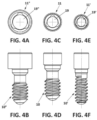
- Figure 4 shows three screw alternatives, A (10"), B (10) and C (10'), according to the present invention, wherein the dimensions of the different parts of the screw vary and the variation of dimensions of the heads (11", 11, 11') of the screw is mainly shown, where the screw A (10") has the head (11") with the larger outer diameter, of approximately (X); the screw B (10) has the head (11) with the intermediate outer diameter; and the screw C (10') has the head (11') with the smaller outer diameter.
- the dimensions of the transverse cross section of the opening are also different and are determined by the diameter of the second circumference (17).
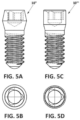
- Figure 5 shows two views of two other examples of screws (10′′′, 10 iv ), respectively.
- the screws of the previous figures have the same configuration (19, 19', 19") with respect to the hollow or housing of the head of the screws although with different dimensions, and they also have different shapes and lengths with respect to other parts of the screw which are not object of the present invention, such as the length of the threaded end or the external shape of the screw to adapt to different housings.
- Figure 6 shows a longitudinal cross section of the screw 10 of Figure 1 and a plan view of the head 11 thereof wherein the different diameters and dimensions making up the shape of the housing 14 can be observed.
- the dimensions of the head 11 of the screw 10 and the housing 14 thereof are determined according to the following ratios between the different parts of the screw 10:
- the outer diameter of the head 11 of the screw 10 is approximately 1.56 times the diameter of the first circumference 16.
- the same determined by the beginning of the wall 22 and the end thereof at the bottom of the hollow 14 is depressed with respect to the outer surface of the head 11 of the screw 10.
- the length between the end of the wall 22 at the bottom of the housing 14 and the upper surface of the screw head 11 is equal to 0.68 times the diameter of the first circumference 16.
- the distance between the beginning of the wall 22 on the side opposite that of the bottom of the housing 14 and the upper surface of the screw head 11 furthest from the end with the thread 12 is 0.20 times the diameter of the first circumference 16.
- the surface between the beginning of the wall 22 and the upper surface of the screw head 11 is inclined or chamfered, between 30° and 60°.
- FIG. 9 to 14 a first preferred embodiment of a screwdriver 100 according to the present invention is shown.
- Said screwdriver 100 with a longitudinal axis "t" preferably has a lower end with an action tip 150, which is introduced in the housing 14 arranged in the head 11 of the screw 10 to cause the rotation thereof, and an upper end preferably having a fastening area 110.
- the body of the screwdriver 100 Arranged between both ends is the body of the screwdriver 100, which can have a handle or body 120 after the upper grip end 110 and followed, immediately before the tip 150, by a rod 130.
- the essential part of the screwdriver 100 is the configuration of the tip 150. In order for the screwdriver 100 to act on the screw 10, the tip 150 must be able to be coupled and act on the geometry and construction of the housing 14 of the screw 10.
- Figure 9 shows a perspective view of the tip 150 of the screwdriver 100 where the main parts thereof are shown.
- the apparently spherical configuration i.e. with a spherical appearance, is shown, defined by curved walls 154 by way of first spherical spindles, separated from each other by depressions 151 also spherical and by way of second spindles and by projections 153, by way of third spherical spindles.
- the third spherical spindles 153 have a thickness less than the first spherical spindles 154, while the spherical depressions 151 have a thickness less than that of the third spherical spindles 153.
- the depressions 151 are preferably a continuation of recesses made in the lower end of the screwdriver rod to weaken the same and enable the screwdriver to be separated into two parts in the event that a certain torque is exceeded and the screw on which said torque is applied does not rotate. This prevents damage to the screw.
- the tip 150 of the screwdriver is stripped at the lower part with an end 152 which may have a conical, spherical or flat shape, although it is not essential for the development of the screwdriver.
- Figure 11 shows a bottom plan view of the head or tip 150 of the screwdriver 100 and the parts described above.
- the infinite transverse cross sections of the tip 150 have the same shape as the transverse cross section of the housing 14 of the screw, with the difference that in the case of the screwdriver said cross sections do not have the same surface as is preferable in the housing of the screw, but rather the different cross sections vary their surface according to the transverse plane determined by the cross section on the spherical tip 150.
- four transverse cross sections are shown according to the cutting planes of the tip 150. It is shown how the surface of the cross sections vary depending on the cutting plane. That is, each of the different transverse cross sections of the tip 150 of the screwdriver is governed by the same ratios as the housing 14 of the screw 10.
- the cross section of the tip 150 with a larger surface will preferably be slightly smaller than the surface of the cross section of the housing 14 of the screw 10 so that the tip 150 of the screwdriver 100 can penetrate the housing 14 of the screw.
- Figure 12 shows a side view of the screwdriver tip, as well as a longitudinal cross section and a transverse cross section thereof wherein the parts and parameters that determine the geometry and shape of the screwdriver head are shown:
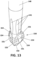
- Figure 13 shows a perspective detailed view of the screwdriver tip with the recesses 141, also shown in other figures, for reducing the cross section of the screwdriver above the tip and facilitate that the same is broken through that section.
- Figure 14 shows successive cross sections of the screwdriver tip.
- the second arcs can have a radii that goes into the body of the tip.
- Figure 15 shows a screw 10 and a screwdriver 100 with an inclination of up to 45° between the longitudinal axis of the screw 10 and the longitudinal axis of the screwdriver 100.
- Said inclination can preferably reach up to 50°.
- the screwdriver can operate on the screw 10 in the entire range between 0° and 45°, and preferably up to 50°.
- Figure 16 is an enlarged detailed view of Figure 15 in which the tip 150 of the screwdriver 100 inside the housing 14 of the screw head 11 is also shown.
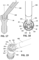
- a cross section of this Figure 16 is shown in Figure 17 where it is shown how the rod 140 of the screwdriver 100 rests on the inclined edge 13 of the housing 14 of the screw 10.
- Figure 18 shows a top view of the previous coupling and
- Figure 19 shows a perspective view of said coupling.
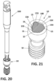
- Figure 20 shows a perspective view of a longitudinal cross section of the mentioned coupling while Figure 21 shows an elevation view of said longitudinal cross section.
- Figures 20 and 21 show a screwdriver 100 on a screw 10, the longitudinal axis "e” of the screw 10 forming 0° with the longitudinal axis "t” of the screwdriver, i.e. both axes coinciding.
- Figure 21 shows a cross section of the tip 150 of the screwdriver 100 where it can be seen how said cross section of the tip 150, according to the first embodiment of the screwdriver, coincides with the cross section of the housing 14 of the screw 10.
- Figure 22 shows a longitudinally cross-sectioned dental implant 200 on which an intermediate element 400 with a dental prosthesis 300 is installed, said intermediate element 400 being fastened to the dental implant 200 by means of a screw 10 and a screwdriver 100 according to the present invention.
- Due to the configuration of the screw 10 and the screwdriver in particular due to the configuration of the housing 14 of the screw and of the tip 150 of the screwdriver, it is possible to act on the screw 10 with the screwdriver 100 when the dental prosthesis has a channel 310 with an inclination greater than 0°, and preferably up to 50°, in the figure, 45° with the axis "d" of the dental implant 200.
- said axis "d" of the dental implant 200 coincides with the axis "e” of the screw 10, such that the screwdriver will act on the screw with the inclination required by the inclination of the channel 310 of the prosthesis 300.
- the tip does not show a first circumference F complementary to the first circumference A of the screw but alternative shapes that do not interfere with said first circumference A of the screw.
- the projections of the tip are inscribed in a second circumference.
- the diameter of the second arcs is different to the one of the previous embodiments, and can be even larger than the previous ones or smaller. Said second arcs could even disappear so that the first arcs could be joined to the area between them through sharp edges.
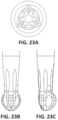
- Figure 23 shows a second exemplary embodiment of a screwdriver according to the present invention. Specifically, two side views and a plan view are shown, where it is shown that the area between the projections of the screwdriver tip is almost straight, that is to say, it would not adapt to the shape of the housing of the screw existing between the projections, such that only the projections of the screwdriver would come in contact with the projections of the hollow of the screw.
- Figure 24 shows a third exemplary embodiment of a screwdriver according to the present invention, wherein the area between the projections of the screwdriver tip is slightly curved and towards the inside of the tip.
- Figure 25 shows a fourth exemplary embodiment of a screwdriver according to the present invention, wherein the area between the projections of the screwdriver tip is curved and towards the inside of the tip in a more pronounced manner than in the previous figure.
- Figure 26 shows a fifth exemplary embodiment of a screwdriver according to the present invention, similar to the screwdriver of the first embodiment, but with the lower pole thereof being pointed.
- Figure 27 shows a fifth exemplary embodiment of a screwdriver according to the present invention, similar to the screwdriver of the first embodiment, but with the lower pole thereof being flat.
Landscapes
- Health & Medical Sciences (AREA)
- Oral & Maxillofacial Surgery (AREA)
- Orthopedic Medicine & Surgery (AREA)
- Dentistry (AREA)
- Epidemiology (AREA)
- Life Sciences & Earth Sciences (AREA)
- Animal Behavior & Ethology (AREA)
- General Health & Medical Sciences (AREA)
- Public Health (AREA)
- Veterinary Medicine (AREA)
- Engineering & Computer Science (AREA)
- Mechanical Engineering (AREA)
- Dental Prosthetics (AREA)
Claims (9)
- Zahnprothesen-Implantatschraube (10), die zur Befestigung eines Zahnelements oder einer Zahnprothese an einem Zahnimplantat angepasst ist, mit einem Kopf (11) an einem Ende und einem Gewinde (12) am gegenüberliegenden Ende, wobei der Kopf einen länglichen zentralen Hohlraum (14) mit Innenwänden (22) aufweist, der sich entlang der Längsachse (e) der Schraube (10) erstreckt und einen Querschnitt senkrecht zur Längsachse (e) des Hohlraums (14) aufweist, wobei der Querschnittsabschnitt Folgendes umfasst:- eine Öffnung des Hohlraums, die aus einer Form besteht, die bestimmt wird durch einen ersten Umfang (16) mit einem ersten Durchmesser und nur drei äußeren ersten Kreisbögen (15), die drei Nocken (15) bestimmen, die die Querfläche der Öffnung vergrößern, wobei die Länge der drei äußeren ersten Kreisbögen (15) kürzer ist als die Länge eines Halbkreises mit demselben Radius wie dem der drei äußeren ersten Kreisbögen (15), und- wobei sich die drei Mittelpunkte der drei äußeren ersten Kreisbögen (15) auf demselben dritten Umfang (18) konzentrisch zum ersten Umfang (16) befinden und die drei Mittelpunkte gleich weit voneinander entfernt sind.
- Schraube nach einem der vorhergehenden Ansprüche, dadurch gekennzeichnet, dass:- der Durchmesser des dritten Umfangs (18) gleich dem 0,87-Fachen des Durchmessers des ersten Umfangs (16) ist und- der Radius der drei äußeren ersten Kreisbögen (15) gleich dem 0,19-Fachen des Durchmessers des ersten Umfangs (16) ist.
- Schraube nach einem der vorhergehenden Ansprüche, dadurch gekennzeichnet, dass die Länge zwischen dem Ende der Innenwand (22) am Boden des Hohlraums (14) und der äußeren Oberfläche des Schraubenkopfes (11) gleich dem 0,68-Fachen des Durchmessers des ersten Umfangs (16) ist.
- Schraube nach einem der Ansprüche 2 oder 3, dadurch gekennzeichnet, dass der Abstand zwischen dem Anfang der Wand (22) in der Öffnung auf der dem Boden des Hohlraums (14) gegenüberliegenden Seite und der oberen Oberfläche des Schraubenkopfes (11), die am weitesten von dem Ende mit dem Gewinde (12) entfernt ist, das 0,20-Fache des Durchmessers des ersten Umfangs (16) beträgt.
- Schraube nach einem der Ansprüche 3 oder 4, dadurch gekennzeichnet, dass die Oberfläche zwischen dem Anfang der Wand (22) und der oberen Oberfläche des Schraubenkopfes (11) zwischen 30° und 60° geneigt/abgeschrägt ist.
- Spannwerkzeug zum Wirken im Hohlraum einer Zahnprothesenschraube, das zur Befestigung eines Zahnelements oder einer Zahnprothese an einem Zahnimplantat angepasst ist und eine Aktionsspitze an einem Ende, die dafür vorgesehen ist, in den Hohlraum der Prothesenschraube eingeführt zu werden, und einen Griff oder eine Stütze an dem Ende, das demjenigen der Spitze gegenüberliegt, aufweist, wobei der Querschnitt der Spitze durch Folgendes bestimmt wird:- einen ersten Umfang (F) mit einem ersten Durchmesser und nur drei Vorsprüngen, die drei Nocken bestimmen, wobei der Querschnitt der Nocken einen ersten äußeren Kreisbogen (153) in jeder Nocke bestimmt, die Länge der drei ersten äußeren Kreisbögen (153) kürzer ist als die Länge eines Halbkreises mit demselben Radius wie dem der drei ersten äußeren Kreisbögen (153), die drei ersten äußeren Kreisbögen (153) in jeder Nocke oder jedem Vorsprung außerhalb des ersten Umfangs (F) liegen und eine Fläche bestimmen, die größer ist als die des ersten Umfangs,- die drei ersten äußeren Kreisbögen (153) in einen zweiten virtuellen Umfang mit einem größeren Durchmesser als der erste Umfang (F) einbeschrieben sind und zu diesem tangential sind, wobei beide Umfänge konzentrisch sind,- die Mittelpunkte jedes ersten äußeren Kreisbogens (153) gleich weit voneinander entfernt sind und sich auf einem dritten Umfang (E) mit einem zum Durchmesser des ersten und zweiten Umfangs konzentrischen Durchmesser befinden, wobei die Verbindung der Mittelpunkte der Radien der ersten äußeren Kreisbögen (153) ein gleichseitiges Dreieck bestimmt, und- der Längsschnitt des Vorsprungs oder der Nocke der Schraubenzieherspitze ebenfalls einen äußeren Bogen bestimmt.
- Kopplungssystem, dadurch gekennzeichnet, dass es eine Schraube nach einem der Ansprüche 1 bis 5 und einen Schraubenzieher nach Anspruch 6 umfasst.
- System nach Anspruch 7, dadurch gekennzeichnet, dass:- der Durchmesser des dritten Umfangs des Werkzeugs (E) das 1/1,17-Fache des Durchmessers des ersten Umfangs der Schraube (16) beträgt,- der Radius jeder Nocke des Werkzeugs (Rot) in ihrem Querschnitt das 1/6,4-Fache des Durchmessers des ersten Umfangs (16) der Schraube beträgt und- der äußere Radius der Schraubenzieherspitze H im Längsschnitt jeder Nocke das 1/0,87-Fache des Durchmessers des ersten Umfangs (16) der Schraube beträgt.
- System nach Anspruch 8, dadurch gekennzeichnet, dass der Querschnitt seiner Spitze durch einen ersten Umfang (F) mit einem ersten Durchmesser und durch die drei ersten äußeren Kreisbögen (153), die sich in jeder Nocke oder jedem Vorsprung außerhalb des ersten Umfangs (F) befinden, bestimmt wird.
Applications Claiming Priority (2)
| Application Number | Priority Date | Filing Date | Title |
|---|---|---|---|
| EP19382587.4A EP3763322A1 (de) | 2019-07-10 | 2019-07-10 | Prothetische zahnschraube, spannwerkzeug und kopplungssystem zwischen den beiden |
| PCT/EP2020/069373 WO2021005158A1 (en) | 2019-07-10 | 2020-07-09 | Prosthetic dental screw implant, tightening tool and coupling system between the two |
Publications (2)
| Publication Number | Publication Date |
|---|---|
| EP3972527A1 EP3972527A1 (de) | 2022-03-30 |
| EP3972527B1 true EP3972527B1 (de) | 2025-02-26 |
Family
ID=67551318
Family Applications (2)
| Application Number | Title | Priority Date | Filing Date |
|---|---|---|---|
| EP19382587.4A Withdrawn EP3763322A1 (de) | 2019-07-10 | 2019-07-10 | Prothetische zahnschraube, spannwerkzeug und kopplungssystem zwischen den beiden |
| EP20739935.3A Active EP3972527B1 (de) | 2019-07-10 | 2020-07-09 | Prothetische zahnimplantatschraube, anziehwerkzeug und kupplungssystem zwischen den beiden |
Family Applications Before (1)
| Application Number | Title | Priority Date | Filing Date |
|---|---|---|---|
| EP19382587.4A Withdrawn EP3763322A1 (de) | 2019-07-10 | 2019-07-10 | Prothetische zahnschraube, spannwerkzeug und kopplungssystem zwischen den beiden |
Country Status (9)
| Country | Link |
|---|---|
| US (2) | US12396827B2 (de) |
| EP (2) | EP3763322A1 (de) |
| AU (1) | AU2020309167A1 (de) |
| CA (1) | CA3144559A1 (de) |
| ES (1) | ES3017937T3 (de) |
| HU (1) | HUE071415T2 (de) |
| PL (1) | PL3972527T3 (de) |
| PT (1) | PT3972527T (de) |
| WO (1) | WO2021005158A1 (de) |
Families Citing this family (6)
| Publication number | Priority date | Publication date | Assignee | Title |
|---|---|---|---|---|
| EP3763322A1 (de) * | 2019-07-10 | 2021-01-13 | Tech Xika PTT, S.L. | Prothetische zahnschraube, spannwerkzeug und kopplungssystem zwischen den beiden |
| GB2602045B (en) * | 2020-12-16 | 2025-02-12 | Exstent Ltd | Model and method of modelling a pulmonary autograft |
| EP4260982A1 (de) * | 2022-04-11 | 2023-10-18 | Bonastre Biomed, SL | Schraube, schraubendreher und schraubenbefestigungssatz |
| EP4450021A1 (de) | 2023-04-21 | 2024-10-23 | Sweden & Martina SpA | Werkzeuge für die zahnimplantologie |
| US20250073002A1 (en) * | 2023-05-05 | 2025-03-06 | Daniel Domingue | Abutment adjusting screw |
| USD1046155S1 (en) * | 2023-05-05 | 2024-10-08 | Daniel Domingue | Dental screw |
Citations (2)
| Publication number | Priority date | Publication date | Assignee | Title |
|---|---|---|---|---|
| DE20108605U1 (de) * | 2001-05-22 | 2001-11-22 | Waller, Peter, 82131 Gauting | Schraubendreher, Bit und Schraubenkopf |
| EP3441041A1 (de) * | 2016-04-04 | 2019-02-13 | Vogul, S.L.U. | Schraube und betätigungswerkzeug für zahnimplantologie |
Family Cites Families (14)
| Publication number | Priority date | Publication date | Assignee | Title |
|---|---|---|---|---|
| US6733291B1 (en) * | 1999-09-27 | 2004-05-11 | Nobel Biocare Usa, Inc. | Implant with internal multi-lobed interlock |
| SE526887C2 (sv) * | 2003-10-01 | 2005-11-15 | Nobel Biocare Ab | Anordning vid implantat med invändig fattning för vridverktyg |
| US7249949B2 (en) * | 2004-06-29 | 2007-07-31 | Lifecore Biomedical, Inc. | Internal connection dental implant |
| CA2680349A1 (en) * | 2007-03-23 | 2008-10-02 | Biomain Ab | Screwdriver and screw member adapted therefore |
| ES2368635B1 (es) * | 2009-04-16 | 2012-09-25 | Ramón Farre Berga | Estructura de acoplamiento entre cabeza de tornillo y herramienta de apriete. |
| DE102011009906A1 (de) * | 2011-01-31 | 2012-08-02 | Holger Zipprich | Dental- Implantatsystem |
| AU2012280708A1 (en) * | 2011-07-06 | 2014-01-23 | Nobel Biocare Services Ag | Screw and driver tool |
| EP2607722B1 (de) * | 2011-12-22 | 2014-02-26 | Straumann Holding AG | Verbindungsschraube für ein Dentalimplantat |
| BR102012029369A2 (pt) * | 2012-11-19 | 2014-09-23 | Esteban Xam-Mar Mangrane | Aperfeiçoamentos introduzidos em conjunto pilar dinâmico |
| US20140236247A1 (en) * | 2013-02-20 | 2014-08-21 | Warsaw Orthopedic, Inc. | Surgical implant system and method |
| EP2932929B1 (de) * | 2014-04-15 | 2017-02-08 | Biedermann Technologies GmbH & Co. KG | Schraubelement zur Verwendung in der spinalen, orthopädischen oder traumatologischen Chirurgie und System mit solch einem Schraubelement und daran angepassten Schraubendreher |
| WO2017070335A1 (en) | 2015-10-20 | 2017-04-27 | Implant Direct Sybron International Llc | Screw and driver tool for dental procedures |
| ES1154360U (es) * | 2016-03-14 | 2016-04-12 | Esteban Xam-Mar Mangrane | Tornillo para implantologia dental |
| EP3763322A1 (de) * | 2019-07-10 | 2021-01-13 | Tech Xika PTT, S.L. | Prothetische zahnschraube, spannwerkzeug und kopplungssystem zwischen den beiden |
-
2019
- 2019-07-10 EP EP19382587.4A patent/EP3763322A1/de not_active Withdrawn
-
2020
- 2020-07-09 HU HUE20739935A patent/HUE071415T2/hu unknown
- 2020-07-09 EP EP20739935.3A patent/EP3972527B1/de active Active
- 2020-07-09 WO PCT/EP2020/069373 patent/WO2021005158A1/en not_active Ceased
- 2020-07-09 PL PL20739935.3T patent/PL3972527T3/pl unknown
- 2020-07-09 PT PT207399353T patent/PT3972527T/pt unknown
- 2020-07-09 AU AU2020309167A patent/AU2020309167A1/en active Pending
- 2020-07-09 US US17/625,459 patent/US12396827B2/en active Active
- 2020-07-09 CA CA3144559A patent/CA3144559A1/en active Pending
- 2020-07-09 ES ES20739935T patent/ES3017937T3/es active Active
-
2025
- 2025-07-25 US US19/280,804 patent/US20250345153A1/en active Pending
Patent Citations (3)
| Publication number | Priority date | Publication date | Assignee | Title |
|---|---|---|---|---|
| DE20108605U1 (de) * | 2001-05-22 | 2001-11-22 | Waller, Peter, 82131 Gauting | Schraubendreher, Bit und Schraubenkopf |
| EP3441041A1 (de) * | 2016-04-04 | 2019-02-13 | Vogul, S.L.U. | Schraube und betätigungswerkzeug für zahnimplantologie |
| US20190151051A1 (en) * | 2016-04-04 | 2019-05-23 | Vogul, S.L.U. | Screw and actuating tool for dental implantology |
Also Published As
| Publication number | Publication date |
|---|---|
| ES3017937T3 (en) | 2025-05-14 |
| PL3972527T3 (pl) | 2025-06-09 |
| HUE071415T2 (hu) | 2025-08-28 |
| PT3972527T (pt) | 2025-03-24 |
| US20220313400A1 (en) | 2022-10-06 |
| EP3972527A1 (de) | 2022-03-30 |
| CA3144559A1 (en) | 2021-01-14 |
| AU2020309167A1 (en) | 2022-01-20 |
| US12396827B2 (en) | 2025-08-26 |
| WO2021005158A1 (en) | 2021-01-14 |
| US20250345153A1 (en) | 2025-11-13 |
| EP3763322A1 (de) | 2021-01-13 |
Similar Documents
| Publication | Publication Date | Title |
|---|---|---|
| US20250345153A1 (en) | Prosthetic dental screw implant, tightening tool and coupling system between the two | |
| US11045288B2 (en) | Screw, tool and assembly for dental implantology | |
| JP4929160B2 (ja) | 摩擦係合可能な表面を有するらせんねじ締め留め具 | |
| KR102489389B1 (ko) | 특정한 임플란트 포스트 기하구조를 구비한 상부구조 지지체 | |
| CN101146491B (zh) | 牙齿植入体 | |
| JP6509211B2 (ja) | 上部構造支持体及び上部構造支持体を製造する方法 | |
| JP6084978B2 (ja) | 歯科用構成要素、歯科用フィクスチャー、および歯科用インプラント | |
| KR102048593B1 (ko) | 치과용 부품 및 치과용 임플란트 | |
| CN105283147B (zh) | 牙科植入物和插入工具 | |
| CN102177353B (zh) | 螺丝的螺丝刀嵌合用十字槽的结构 | |
| JP2000512883A (ja) | 歯科用インプラントおよび歯科用インプラントをともなう装置 | |
| KR102440721B1 (ko) | 특정한 내측 및 외측 기하구조를 구비한 상부구조 지지체 | |
| EP0046010A1 (de) | Schrauben und Schraubenzieher-Kombination | |
| CA2562696A1 (en) | Internal connection dental implant | |
| KR102932723B1 (ko) | 상부 구조물과 임플란트 바디 사이의 조립 인터페이스 | |
| AU2012200267B2 (en) | Torque transmission tool | |
| EP4450021A1 (de) | Werkzeuge für die zahnimplantologie | |
| JP2007002880A (ja) | 十字穴付ねじ | |
| KR20230077714A (ko) | 트위스트 기구 |
Legal Events
| Date | Code | Title | Description |
|---|---|---|---|
| STAA | Information on the status of an ep patent application or granted ep patent |
Free format text: STATUS: UNKNOWN |
|
| STAA | Information on the status of an ep patent application or granted ep patent |
Free format text: STATUS: THE INTERNATIONAL PUBLICATION HAS BEEN MADE |
|
| PUAI | Public reference made under article 153(3) epc to a published international application that has entered the european phase |
Free format text: ORIGINAL CODE: 0009012 |
|
| STAA | Information on the status of an ep patent application or granted ep patent |
Free format text: STATUS: REQUEST FOR EXAMINATION WAS MADE |
|
| 17P | Request for examination filed |
Effective date: 20211222 |
|
| AK | Designated contracting states |
Kind code of ref document: A1 Designated state(s): AL AT BE BG CH CY CZ DE DK EE ES FI FR GB GR HR HU IE IS IT LI LT LU LV MC MK MT NL NO PL PT RO RS SE SI SK SM TR |
|
| DAV | Request for validation of the european patent (deleted) | ||
| DAX | Request for extension of the european patent (deleted) | ||
| STAA | Information on the status of an ep patent application or granted ep patent |
Free format text: STATUS: EXAMINATION IS IN PROGRESS |
|
| 17Q | First examination report despatched |
Effective date: 20230615 |
|
| GRAP | Despatch of communication of intention to grant a patent |
Free format text: ORIGINAL CODE: EPIDOSNIGR1 |
|
| STAA | Information on the status of an ep patent application or granted ep patent |
Free format text: STATUS: GRANT OF PATENT IS INTENDED |
|
| INTG | Intention to grant announced |
Effective date: 20241209 |
|
| GRAS | Grant fee paid |
Free format text: ORIGINAL CODE: EPIDOSNIGR3 |
|
| GRAA | (expected) grant |
Free format text: ORIGINAL CODE: 0009210 |
|
| STAA | Information on the status of an ep patent application or granted ep patent |
Free format text: STATUS: THE PATENT HAS BEEN GRANTED |
|
| AK | Designated contracting states |
Kind code of ref document: B1 Designated state(s): AL AT BE BG CH CY CZ DE DK EE ES FI FR GB GR HR HU IE IS IT LI LT LU LV MC MK MT NL NO PL PT RO RS SE SI SK SM TR |
|
| REG | Reference to a national code |
Ref country code: GB Ref legal event code: FG4D |
|
| REG | Reference to a national code |
Ref country code: CH Ref legal event code: EP |
|
| REG | Reference to a national code |
Ref country code: DE Ref legal event code: R096 Ref document number: 602020046751 Country of ref document: DE |
|
| REG | Reference to a national code |
Ref country code: PT Ref legal event code: SC4A Ref document number: 3972527 Country of ref document: PT Date of ref document: 20250324 Kind code of ref document: T Free format text: AVAILABILITY OF NATIONAL TRANSLATION Effective date: 20250319 |
|
| REG | Reference to a national code |
Ref country code: IE Ref legal event code: FG4D |
|
| REG | Reference to a national code |
Ref country code: SE Ref legal event code: TRGR |
|
| REG | Reference to a national code |
Ref country code: GR Ref legal event code: EP Ref document number: 20250400687 Country of ref document: GR Effective date: 20250514 |
|
| REG | Reference to a national code |
Ref country code: NL Ref legal event code: MP Effective date: 20250226 |
|
| PG25 | Lapsed in a contracting state [announced via postgrant information from national office to epo] |
Ref country code: RS Free format text: LAPSE BECAUSE OF FAILURE TO SUBMIT A TRANSLATION OF THE DESCRIPTION OR TO PAY THE FEE WITHIN THE PRESCRIBED TIME-LIMIT Effective date: 20250526 |
|
| PG25 | Lapsed in a contracting state [announced via postgrant information from national office to epo] |
Ref country code: FI Free format text: LAPSE BECAUSE OF FAILURE TO SUBMIT A TRANSLATION OF THE DESCRIPTION OR TO PAY THE FEE WITHIN THE PRESCRIBED TIME-LIMIT Effective date: 20250226 |
|
| PGFP | Annual fee paid to national office [announced via postgrant information from national office to epo] |
Ref country code: PL Payment date: 20250620 Year of fee payment: 6 |
|
| REG | Reference to a national code |
Ref country code: LT Ref legal event code: MG9D |
|
| PG25 | Lapsed in a contracting state [announced via postgrant information from national office to epo] |
Ref country code: IS Free format text: LAPSE BECAUSE OF FAILURE TO SUBMIT A TRANSLATION OF THE DESCRIPTION OR TO PAY THE FEE WITHIN THE PRESCRIBED TIME-LIMIT Effective date: 20250626 Ref country code: NO Free format text: LAPSE BECAUSE OF FAILURE TO SUBMIT A TRANSLATION OF THE DESCRIPTION OR TO PAY THE FEE WITHIN THE PRESCRIBED TIME-LIMIT Effective date: 20250526 |
|
| PG25 | Lapsed in a contracting state [announced via postgrant information from national office to epo] |
Ref country code: NL Free format text: LAPSE BECAUSE OF FAILURE TO SUBMIT A TRANSLATION OF THE DESCRIPTION OR TO PAY THE FEE WITHIN THE PRESCRIBED TIME-LIMIT Effective date: 20250226 |
|
| PG25 | Lapsed in a contracting state [announced via postgrant information from national office to epo] |
Ref country code: HR Free format text: LAPSE BECAUSE OF FAILURE TO SUBMIT A TRANSLATION OF THE DESCRIPTION OR TO PAY THE FEE WITHIN THE PRESCRIBED TIME-LIMIT Effective date: 20250226 |
|
| PG25 | Lapsed in a contracting state [announced via postgrant information from national office to epo] |
Ref country code: LV Free format text: LAPSE BECAUSE OF FAILURE TO SUBMIT A TRANSLATION OF THE DESCRIPTION OR TO PAY THE FEE WITHIN THE PRESCRIBED TIME-LIMIT Effective date: 20250226 |
|
| PGFP | Annual fee paid to national office [announced via postgrant information from national office to epo] |
Ref country code: PT Payment date: 20250605 Year of fee payment: 6 |
|
| PG25 | Lapsed in a contracting state [announced via postgrant information from national office to epo] |
Ref country code: BG Free format text: LAPSE BECAUSE OF FAILURE TO SUBMIT A TRANSLATION OF THE DESCRIPTION OR TO PAY THE FEE WITHIN THE PRESCRIBED TIME-LIMIT Effective date: 20250226 |
|
| PGFP | Annual fee paid to national office [announced via postgrant information from national office to epo] |
Ref country code: CZ Payment date: 20250620 Year of fee payment: 6 |
|
| PGFP | Annual fee paid to national office [announced via postgrant information from national office to epo] |
Ref country code: HU Payment date: 20250625 Year of fee payment: 6 |
|
| REG | Reference to a national code |
Ref country code: AT Ref legal event code: MK05 Ref document number: 1769911 Country of ref document: AT Kind code of ref document: T Effective date: 20250226 |
|
| REG | Reference to a national code |
Ref country code: HU Ref legal event code: AG4A Ref document number: E071415 Country of ref document: HU |
|
| PG25 | Lapsed in a contracting state [announced via postgrant information from national office to epo] |
Ref country code: SM Free format text: LAPSE BECAUSE OF FAILURE TO SUBMIT A TRANSLATION OF THE DESCRIPTION OR TO PAY THE FEE WITHIN THE PRESCRIBED TIME-LIMIT Effective date: 20250226 |
|
| PGFP | Annual fee paid to national office [announced via postgrant information from national office to epo] |
Ref country code: ES Payment date: 20250805 Year of fee payment: 6 |
|
| PG25 | Lapsed in a contracting state [announced via postgrant information from national office to epo] |
Ref country code: DK Free format text: LAPSE BECAUSE OF FAILURE TO SUBMIT A TRANSLATION OF THE DESCRIPTION OR TO PAY THE FEE WITHIN THE PRESCRIBED TIME-LIMIT Effective date: 20250226 |
|
| PGFP | Annual fee paid to national office [announced via postgrant information from national office to epo] |
Ref country code: DE Payment date: 20250729 Year of fee payment: 6 |
|
| PGFP | Annual fee paid to national office [announced via postgrant information from national office to epo] |
Ref country code: GR Payment date: 20250729 Year of fee payment: 6 |
|
| PGFP | Annual fee paid to national office [announced via postgrant information from national office to epo] |
Ref country code: TR Payment date: 20250708 Year of fee payment: 6 Ref country code: IT Payment date: 20250721 Year of fee payment: 6 |
|
| PGFP | Annual fee paid to national office [announced via postgrant information from national office to epo] |
Ref country code: GB Payment date: 20250728 Year of fee payment: 6 |
|
| PG25 | Lapsed in a contracting state [announced via postgrant information from national office to epo] |
Ref country code: AT Free format text: LAPSE BECAUSE OF FAILURE TO SUBMIT A TRANSLATION OF THE DESCRIPTION OR TO PAY THE FEE WITHIN THE PRESCRIBED TIME-LIMIT Effective date: 20250226 |
|
| PGFP | Annual fee paid to national office [announced via postgrant information from national office to epo] |
Ref country code: FR Payment date: 20250725 Year of fee payment: 6 |
|
| PGFP | Annual fee paid to national office [announced via postgrant information from national office to epo] |
Ref country code: SE Payment date: 20250727 Year of fee payment: 6 Ref country code: CH Payment date: 20250801 Year of fee payment: 6 |
|
| PG25 | Lapsed in a contracting state [announced via postgrant information from national office to epo] |
Ref country code: EE Free format text: LAPSE BECAUSE OF FAILURE TO SUBMIT A TRANSLATION OF THE DESCRIPTION OR TO PAY THE FEE WITHIN THE PRESCRIBED TIME-LIMIT Effective date: 20250226 |
|
| PGFP | Annual fee paid to national office [announced via postgrant information from national office to epo] |
Ref country code: IE Payment date: 20250728 Year of fee payment: 6 |
|
| PGFP | Annual fee paid to national office [announced via postgrant information from national office to epo] |
Ref country code: RO Payment date: 20250701 Year of fee payment: 6 |
|
| PG25 | Lapsed in a contracting state [announced via postgrant information from national office to epo] |
Ref country code: SK Free format text: LAPSE BECAUSE OF FAILURE TO SUBMIT A TRANSLATION OF THE DESCRIPTION OR TO PAY THE FEE WITHIN THE PRESCRIBED TIME-LIMIT Effective date: 20250226 |
|
| REG | Reference to a national code |
Ref country code: DE Ref legal event code: R097 Ref document number: 602020046751 Country of ref document: DE |
|
| PLBE | No opposition filed within time limit |
Free format text: ORIGINAL CODE: 0009261 |
|
| STAA | Information on the status of an ep patent application or granted ep patent |
Free format text: STATUS: NO OPPOSITION FILED WITHIN TIME LIMIT |
|
| 26N | No opposition filed |
Effective date: 20251127 |
|
| PG25 | Lapsed in a contracting state [announced via postgrant information from national office to epo] |
Ref country code: LU Free format text: LAPSE BECAUSE OF NON-PAYMENT OF DUE FEES Effective date: 20250709 |
|
| REG | Reference to a national code |
Ref country code: BE Ref legal event code: MM Effective date: 20250731 |
|
| PG25 | Lapsed in a contracting state [announced via postgrant information from national office to epo] |
Ref country code: BE Free format text: LAPSE BECAUSE OF NON-PAYMENT OF DUE FEES Effective date: 20250731 |