EP3970872A1 - Sheet bending machine with stop system - Google Patents
Sheet bending machine with stop system Download PDFInfo
- Publication number
- EP3970872A1 EP3970872A1 EP21196703.9A EP21196703A EP3970872A1 EP 3970872 A1 EP3970872 A1 EP 3970872A1 EP 21196703 A EP21196703 A EP 21196703A EP 3970872 A1 EP3970872 A1 EP 3970872A1
- Authority
- EP
- European Patent Office
- Prior art keywords
- sub
- sheet metal
- working machine
- finger
- support rails
- Prior art date
- Legal status (The legal status is an assumption and is not a legal conclusion. Google has not performed a legal analysis and makes no representation as to the accuracy of the status listed.)
- Pending
Links
Images


Classifications
-
- B—PERFORMING OPERATIONS; TRANSPORTING
- B21—MECHANICAL METAL-WORKING WITHOUT ESSENTIALLY REMOVING MATERIAL; PUNCHING METAL
- B21D—WORKING OR PROCESSING OF SHEET METAL OR METAL TUBES, RODS OR PROFILES WITHOUT ESSENTIALLY REMOVING MATERIAL; PUNCHING METAL
- B21D5/00—Bending sheet metal along straight lines, e.g. to form simple curves
- B21D5/002—Positioning devices
-
- B—PERFORMING OPERATIONS; TRANSPORTING
- B21—MECHANICAL METAL-WORKING WITHOUT ESSENTIALLY REMOVING MATERIAL; PUNCHING METAL
- B21D—WORKING OR PROCESSING OF SHEET METAL OR METAL TUBES, RODS OR PROFILES WITHOUT ESSENTIALLY REMOVING MATERIAL; PUNCHING METAL
- B21D43/00—Feeding, positioning or storing devices combined with, or arranged in, or specially adapted for use in connection with, apparatus for working or processing sheet metal, metal tubes or metal profiles; Associations therewith of cutting devices
- B21D43/26—Stops
-
- B—PERFORMING OPERATIONS; TRANSPORTING
- B21—MECHANICAL METAL-WORKING WITHOUT ESSENTIALLY REMOVING MATERIAL; PUNCHING METAL
- B21D—WORKING OR PROCESSING OF SHEET METAL OR METAL TUBES, RODS OR PROFILES WITHOUT ESSENTIALLY REMOVING MATERIAL; PUNCHING METAL
- B21D5/00—Bending sheet metal along straight lines, e.g. to form simple curves
- B21D5/04—Bending sheet metal along straight lines, e.g. to form simple curves on brakes making use of clamping means on one side of the work
- B21D5/042—With a rotational movement of the bending blade
Definitions
- the present invention relates to a sheet metal processing machine for processing metal sheets along a processing line.
- Sheet metal working machines of this type which can in particular be a swivel bending machine for bending sheet metal along a bending line or around a bending line (corresponding to the processing line), typically have a stop system with at least one stop element for an edge of the sheet metal to be processed and an adjustment mechanism for adjustment the position of the at least one stop element (relative to the machining line).
- a (continuous or interrupted) stop bar can be used as a stop element, which typically runs parallel to the processing line, the distance between the stop bar and the processing line being adjustable within predetermined limits by means of the adjustment mechanism.
- a plurality of separate stop elements are often provided, which form stop points for the edge of a sheet metal to be processed, the stop points lying on a straight line (typically running parallel to the bending line) and the distance between the stop points is suitably adjustable to the bending line by means of the adjustment mechanism for the bending process desired in each case.
- sheet metal is processed (bended) by first clamping the sheet metal, suitably positioned by means of the at least one stop element, between an upper and a lower beam, by the upper beam previously in an open position being adjusted by suitable (e.g. hydraulic or electric) servomotors is driven down into a closed position in which the sheet is held firmly between the upper and lower beam.
- suitable (e.g. hydraulic or electric) servomotors is driven down into a closed position in which the sheet is held firmly between the upper and lower beam.
- the processing or bending process that takes place along the (straight) processing or bending line can then take place in that a bending beam of the swivel bending machine that is brought into contact with the sheet metal performs a defined swiveling process, with which the sheet metal is bent at a predetermined angle around the bending line will.
- the sheet metal working machine has a stop system with at least one stop element for an edge of the sheet metal to be processed and an adjustment mechanism for adjusting the position of the at least one stop element.
- the adjustment mechanism has two support rails arranged parallel to one another and a plurality of finger rails, each finger rail being articulated (in particular rotatable) attached to both support rails and with its front end defining the position of the at least one stop element or forming such a stop element.
- Each carrier rail is articulated via compensating levers to two carriages of the adjustment mechanism arranged on the left and right of the center of the carrier rail, which can each be moved along a (linear) guide provided for this purpose perpendicular to the bending line.
- the invention provides that the support rails are aligned parallel to the processing line when the adjustment mechanism is in a basic position and at an angle to the processing line when the adjustment mechanism is in an inclined position, while the finger strips, in particular due to the articulated attachment to the support rails, are aligned both in the basic position and are aligned in the inclined position perpendicular to the machining line.
- the adjustment mechanism has a bearing on at least one mounting rail acting centering mechanism, with which the pivot point of both support rails during the transition from the basic position to the inclined position in a - is held central region of the respective support rail - based on the longitudinal axis of the support rail.
- the stop system of the sheet metal processing machine according to the invention which can in particular be a swivel bending machine (often also referred to as a folding machine), has a plurality of finger strips, each of which with its front end forms a stop element for the edge of the sheet metal to be processed or bent form or specify the position of the at least one stop element.
- All finger strips preferably in their rear area, are articulated, in particular rotatable, to two support rails running parallel to one another in such a way that they are also articulated when the support rails move from a basic position oriented parallel to the processing line into an inclined position oblique thereto are transferred (with their longitudinal axis) are always aligned perpendicularly to the processing line.
- the front end of the respective finger strip which defines the stop for a metal sheet and is preferably rounded, always points perpendicularly in the direction of the bending line, which ensures an equally well-defined stop for the metal sheet in every position of the adjustment mechanism.
- the two support rails which are oriented parallel to one another, are articulated on the left and right (relative to the center of the support rails viewed in the longitudinal extension) via suitable compensating levers each on a carriage that can be moved linearly along a guide, with the compensating levers being provided and necessary for this purpose, in order to to compensate for the misalignment caused by tilting the support rails.
- the centering mechanism used according to the invention ensures that the support rails are rotated about a pivot point that is always located in a central area of the respective support rail during the transition from the basic to the inclined position, it is achieved that - in relation to the longitudinal extent of the support rails - In the central area of the support rail, finger strips articulated in the transition from the basic to the inclined position show little or no lateral offset, while the finger strips mounted on the edge of the support rails move slightly inwards during the transition to the inclined position.
- the fulcrum would be at a lateral edge of the support rail, then the finger strips located on the side of the fulcrum would have no lateral offset
- the centering mechanism provided according to the invention also stabilizes the articulation of the carrier rails to the linearly guided carriage via the compensating lever, since this articulation alone would not be suitable for specifying the position of the pivot point of the carrier rails when tilting.
- the adjustment mechanism of the stop system of the sheet metal working machine makes do with exactly two linear guides arranged to the left and right of the center (i.e. preferably at the edge) in relation to the longitudinal extent of the bending line or the support rails for adjusting the stop system, which means that in particular no third
- a linear guide for the stop system on the sheet metal working machine that is articulated centrally on the support rails must be provided.
- the transition of the adjusting mechanism from the basic position to the inclined position can take place by moving one of the two carriages on the guide assigned to it, while the second carriage is not moved.
- the pivot point according to the invention in one middle area of the respective mounting rail. If both carriages are moved simultaneously and at the same speed in opposite directions on their respective guides, the support rails rotate by one in the middle region of the respective support rail without additional linear displacement.
- the pivot point of the support rails is kept in the middle area during the transition from the basic to the inclined position, it is of course particularly preferred if the pivot point is always exactly in the middle of the respective support rail. In principle, however, it is sufficient for the realization of the advantages according to the invention if the pivot point is only in a central area, which can, for example, make up the middle 20% or 10% of the entire length of the support rail.
- the centering mechanism provided according to the invention can basically be realized in different ways, in particular by a suitable lever system as described in more detail below, by an arrangement of two toothed racks which are pivotably attached to the support rails and are coupled by means of a pinion, or by a suitable cable arrangement, by means of which the pivot point could also be held centrally on the mounting rail.
- the centering mechanism is advantageously realized by a lever mechanism.
- the centering mechanism has a centering rocker with a swivel joint and two free ends, the swivel joint based on a longitudinal extent of the support rails is mounted approximately centrally on one of the two support rails and one of two articulation points of the relevant support rail, which are arranged eccentrically and symmetrically to the center of the support rail in relation to the longitudinal extent of the support rails, via a coupling rod in each case in the area of one of the two free ends coupled with the centering rocker.
- a finger bar attached centrally to the two mounting rails in relation to the longitudinal extent of the mounting rail is articulated at the same place on a mounting rail as the pivot joint of the centering rocker, so that the finger bar in question can be moved during the transition from the basic position to the Inclination has no lateral offset.
- the finger rails are arranged at least partially in recesses provided for this purpose in a machine table, a holder or the lower beam of the sheet metal working machine or can be moved into them, with the recesses being dimensioned in such a way that the transition from the basic position lateral offset of the finger rails resulting from the skewing is taken into account.
- each support rail is articulated by means of an angled compensating lever on each of the two carriages, the two compensating levers assigned to each carriage being coupled to one another by means of a coupling rod.
- each of the finger strips preferably forms a separate stop element for the sheet metal to be processed.
- a stop bar functioning as a stop element is provided on each finger bar or that the plurality of finger bars specify the position for a stop bar connecting all finger bars.
- Swivel bending machine is, in which the processing line is thus a bending line.
- Such a swivel bending machine typically has—in addition to the stop system designed according to the invention—a lower beam, an upper beam and a bending beam, as already described in the introduction to the prior art.
- a sheet metal working machine can also be guillotine shears, in which the working line is formed by a cutting edge.
- the sheet metal to be cut is typically held by a hold-down device and cut using a cutting tool consisting of a movable upper blade and a fixed lower blade.
- the illustrated embodiment of the present invention relates to a sheet metal working machine 1 for working sheet metal 2 along a working line B, the illustrated embodiment being a swivel bending machine for bending sheet metal around a bending line (corresponding to the working line B).
- This has a fixed lower beam 3, which can be moved in the usual way in the vertical direction between an open position and a closed position (cf. 2 and 4 ) Movable upper beam 4 and one for bending the sheet metal 2 clamped between the upper beam 4 and the lower beam 3 around the machining or bending line B according to arrow S (cf. 2 and 4 ) pivotable bending beam 5 on.
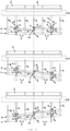
- the in the Figures 1 - 4 Sheet metal working machine 1 shown also has a in the Figures 5 - 10 Stop system illustrated in more detail with, in the given example, a total of five stop elements A 1 , A 2 , A 3 , A 4 , A 5 for the edge R of the metal sheet 2 to be bent and an adjustment mechanism 6 arranged on the rear of the machine for adjusting the position of the five stop elements A 1 , A 2 , A3 , A4 , A5 .
- the adjustment mechanism 6 in turn comprises two support rails 7, 8 arranged parallel to one another and a plurality of finger strips F 1 , F 2 , F 3 , F 4 , F 5 , each finger strip F 1 , F 2 , F 3 , F 4 , F 5 is rotatably articulated at first articulation points D 1 , D 2 , D 3 , D 4 , D 5 on the rear support rail 7 and at second articulation points E 1 , E 2 , E 3 , E 4 , E 5 is rotatably articulated on the front support rail 8 ( see. 6 ) and forms a stop element A 1 , A 2 , A 3 , A 4 , A 5 with its front end.
- the pivot points D 1 , D 2 , D 3 , D 4 , D 5 , E 1 , E 2 , E 3 , E 4 , E 5 are arranged on the respective support rail 7, 8 symmetrically to the center, with one of the pivot points D 3 , E 3 based on the longitudinal extension of the respective support rail 7, 8 is centered on this.
- Each support rail 7, 8 is connected via compensating levers L 1 , L 2 or R 1 , R 2 (coupled to one another by means of a coupling rod K 1 , K 2 and angled) on two carriages 9 , 10 of the adjustment mechanism arranged on the left and right of the middle of the support rail 6 articulated, each along a the guide 11, 12 provided for this purpose can be moved perpendicularly to the bending line B.
- the carriages 9, 10 can be moved on the linear guide 11, 12 with the aid of an electric motor (not shown) or another suitable (e.g. hydraulic) drive unit, independently of one another, in order to adjust the adjustment mechanism 6 to convert by moving only one of the two carriages 9, 10 from the basic position to the inclined position, which further below with reference to 10 will be explained in more detail.
- an electric motor not shown
- another suitable (e.g. hydraulic) drive unit independently of one another, in order to adjust the adjustment mechanism 6 to convert by moving only one of the two carriages 9, 10 from the basic position to the inclined position, which further below with reference to 10 will be explained in more detail.
- a suitable control can be used to ensure that the two carriages 9, 10 can also be moved in a coupled manner while maintaining the basic position or a certain inclined position.
- the mounting rails are in the (e.g. in the Figures 5, 6 and 9 shown) basic position of the adjustment mechanism 6 parallel to the processing or bending line B and in a (e.g. in the 1 and 3 illustrated) inclined position of the adjusting mechanism 6 aligned obliquely to the processing or bending line B, while the finger strips F 1 , F 2 , F 3 , F 4 , F 5 both in the basic position and in the inclined position perpendicular to the processing or bending line B are aligned.
- the adjusting mechanism 6 has one in the Figures 7 - 10 centering mechanism 13 shown in more detail, with which the pivot points P 1 , P 2 (cf. 10 ) of both support rails 7, 8 in the transition from the basic position to the inclined position in a central area Z of the respective Support rail 7, 8 (or in the present case held exactly in the middle of the relevant support rail 7, 8.
- the centering mechanism 13 is realized by a lever system which has a centering rocker 14 with a swivel joint 15 and two free ends 16, 17.
- the rotary joint 15 is mounted approximately centrally on one of the two support rails 7, 8, in the example given on the support rail 8 lying closer to the bending line B, in relation to the longitudinal extension of the support rails 7, 8.
- One of two pivot points 18, 19 of the respective mounting rail 8, which are arranged eccentrically and symmetrically to the center of the mounting rail 8 in relation to the longitudinal extent of the mounting rail 8, is connected to the centering rocker 14 via a respective coupling rod 20, 21 in the area of one of the two free ends 16, 17 coupled to corresponding pivot points 22, 23 (cf. 8 ), whereby in this case the finger strip F 3 articulated centrally on the two support rails 7, 8 is articulated at the same location E 3 on the support rail 8 as the rotary joint 15 of the centering rocker 14.
- Recesses 24, 25, 26, 27, 28 are also provided on the lower beam 3, in which the finger strips F 1 , F 2 , F 3 , F 4 , F 5 at least partially with their lower edge when approaching the bending line B are included, with a machine table not shown in the given figures having corresponding recesses for (partially) accommodating the finger strips F 1 , F 2 , F 3 , F 4 , F 5 .
- FIG 10 shows a basic position of the adjusting mechanism 6 with support rails 7, 8 oriented parallel to the bending line B.
- the two carriages 9, 10 arranged on the left and right of the middle of the support rail can be moved independently of one another according to the double arrows U, V on the respective linear guide 11, 12.
- the transition to the respective inclined position corresponds to a rotation of the support rails due to the lateral articulation of the support rails 7, 8 to the carriages 9, 10 via the compensating levers L1 , L2 , R1 , R2 and due to the centering mechanism 13 already described in more detail above 7, 8 around the central pivot points P 1 , P 2 (with additional linear displacement perpendicular to the bending line), as a result of which the finger strip F 3 , which is hinged in the middle of the support rails 7, 8, does not show any lateral offset during the transition to the respective inclined position, as is shown by the in 10 shown in solid dashed line from top to bottom.
Landscapes
- Engineering & Computer Science (AREA)
- Mechanical Engineering (AREA)
- Bending Of Plates, Rods, And Pipes (AREA)
Abstract
Die vorliegende Erfindung betrifft eine Blechbearbeitungsmaschine (1) zum Bearbeiten von Blechen (2) längs einer Bearbeitungslinie (B), wobei die Blechbearbeitungsmaschine (1) ein Anschlagsystem mit wenigstens einem Anschlagelement (A<sub>1,</sub> A<sub>2</sub>, A<sub>3</sub>, A<sub>4</sub>, A<sub>5</sub>) für einen Rand (R) des zu bearbeitenden Blechs (2) und eine Verstellmechanik (6) zur Einstellung der Position des wenigstens einen Anschlagelements aufweist. Die Verstellmechanik (6) weist zwei parallel zueinander angeordnete Tragschienen (7, 8) sowie eine Mehrzahl an Fingerleisten (F<sub>1</sub>, F<sub>2</sub>, F<sub>3</sub>, F<sub>4</sub>, F<sub>5</sub>) auf, wobei jede Fingerleiste gelenkig an beiden Tragschienen (7, 8) befestigt ist und mit ihrem vorderen Ende (E) die Position des wenigstens einen Anschlagelements (A<sub>1</sub>, A<sub>2</sub>, A<sub>3</sub>, A<sub>4</sub>, A<sub>5</sub>) vorgibt oder ein solches bildet. Jede Tragschiene (7, 8) ist über Ausgleichshebel (L<sub>1</sub>, L<sub>2</sub>, R<sub>1</sub>, R<sub>2</sub>) an zwei links- und rechtsseitig der Tragschienenmitte angeordneten Schlitten (9, 10) angelenkt, die jeweils längs einer hierfür vorgesehenen Führung (11, 12) senkrecht zur Bearbeitungslinie (B) verfahrbar sind. Die Tragschienen (7, 8) sind in einer Grundstellung parallel zur Bearbeitungslinie (B) und in einer Schrägstellung schräg zur Bearbeitungslinie (B) ausgerichtet. Die Fingerleisten (F<sub>1</sub>, F<sub>2</sub>, F<sub>3</sub>, F<sub>4</sub>, F<sub>5</sub>) sind sowohl in der Grundstellung als auch in der Schrägstellung senkrecht zur Bearbeitungslinie (B) ausgerichtet. Schließlich weist die Verstellmechanik (6) einen auf wenigstens eine Tragschiene (7, 8) einwirkenden Zentriermechanismus (13) auf, mit welchem der Drehpunkt beider Tragschienen (7, 8) beim Übergang von der Grundstellung in die Schrägstellung in einem mittleren Bereich der jeweiligen Tragschiene (7, 8) gehalten wird.The present invention relates to a sheet metal working machine (1) for processing sheet metal (2) along a processing line (B), the sheet metal working machine (1) having a stop system with at least one stop element (A<sub>1,</sub>A<sub> 2</sub>, A<sub>3</sub>, A<sub>4</sub>, A<sub>5</sub>) for an edge (R) of the sheet to be machined (2) and an adjusting mechanism (6) for adjusting the position of the at least one stop element. The adjustment mechanism (6) has two support rails (7, 8) arranged parallel to one another and a plurality of finger strips (F<sub>1</sub>, F<sub>2</sub>, F<sub>3</sub> >, F<sub>4</sub>, F<sub>5</sub>), each finger bar being articulated on both support rails (7, 8) and with its front end (E) the position of the at least a stop element (A<sub>1</sub>, A<sub>2</sub>, A<sub>3</sub>, A<sub>4</sub>, A<sub>5</ sub>) or forms one. Each support rail (7, 8) is connected via compensating levers (L<sub>1</sub>, L<sub>2</sub>, R<sub>1</sub>, R<sub>2</sub> ) articulated to two carriages (9, 10) arranged on the left and right of the center of the support rail, which can each be moved along a guide (11, 12) provided for this purpose, perpendicular to the processing line (B). The support rails (7, 8) are aligned parallel to the processing line (B) in a basic position and at an angle to the processing line (B) in an inclined position. The finger bars (F<sub>1</sub>, F<sub>2</sub>, F<sub>3</sub>, F<sub>4</sub>, F<sub>5</ sub>) are aligned perpendicular to the processing line (B) both in the basic position and in the inclined position. Finally, the adjustment mechanism (6) has a centering mechanism (13) which acts on at least one support rail (7, 8) and with which the pivot point of both support rails (7, 8) is located in a central area of the respective support rail during the transition from the basic position to the inclined position (7, 8) is held.
Description
Die vorliegende Erfindung betrifft eine Blechbearbeitungsmaschine zum Bearbeiten von Blechen längs einer Bearbeitungslinie.The present invention relates to a sheet metal processing machine for processing metal sheets along a processing line.
Derartige Blechbearbeitungsmaschinen, bei denen es sich insbesondere um eine Schwenkbiegemaschine zum Biegen von Blechen längs einer bzw. um eine (der Bearbeitungslinie entsprechende) Biegelinie handeln kann, weisen typischerweise ein Anschlagsystem mit wenigstens einem Anschlagelement für einen Rand des zu bearbeitenden Blechs und eine Verstellmechanik zur Einstellung der Position des wenigstens einen Anschlagelements (relativ zur Bearbeitungslinie) auf. Als Anschlagelement kann dabei eine (durchgehende oder unterbrochene) Anschlagleiste Verwendung finden, die typischerweise parallel zur Bearbeitungslinie verläuft, wobei mittels der Verstellmechanik der Abstand der Anschlagleiste von der Bearbeitungslinie innerhalb vorgegebener Grenzen einstellbar ist. Häufig sind bei gattungsgemäßen Blechbearbeitungsmaschinen anstelle einer einzigen Anschlagleiste auch eine Mehrzahl an separaten Anschlagelementen vorgesehen, die Anschlagpunkte für den Rand eines zu bearbeitenden Blechs ausbilden, wobei die Anschlagpunkte auf einer geraden (typischerweise parallel zur Biegelinie verlaufenden) Linie liegen, und wobei der Abstand der Anschlagpunkte zur Biegelinie mittels der Verstellmechanik für den jeweils gewünschten Biegevorgang geeignet einstellbar ist.Sheet metal working machines of this type, which can in particular be a swivel bending machine for bending sheet metal along a bending line or around a bending line (corresponding to the processing line), typically have a stop system with at least one stop element for an edge of the sheet metal to be processed and an adjustment mechanism for adjustment the position of the at least one stop element (relative to the machining line). A (continuous or interrupted) stop bar can be used as a stop element, which typically runs parallel to the processing line, the distance between the stop bar and the processing line being adjustable within predetermined limits by means of the adjustment mechanism. In sheet metal working machines of this type, instead of a single stop bar, a plurality of separate stop elements are often provided, which form stop points for the edge of a sheet metal to be processed, the stop points lying on a straight line (typically running parallel to the bending line) and the distance between the stop points is suitably adjustable to the bending line by means of the adjustment mechanism for the bending process desired in each case.
Bei Schwenkbiegemaschinen erfolgt das Bearbeiten (Biegen) eines Blechs, indem das mittels des wenigstens einen Anschlagelements geeignet positionierte Blech zunächst zwischen einer Ober- und einer Unterwange eingespannt wird, indem die zuvor in einer Öffnungsstellung befindliche Oberwange durch geeignete (z.B. hydraulische oder elektrische) Stellmotoren nach unten in eine Schließstellung gefahren wird, in welcher das Blech fest zwischen der Ober- und Unterwange gehalten ist. Anschließend kann der längs der (geraden) Bearbeitungs- bzw. Biegelinie erfolgende Bearbeitungs- bzw. Biegevorgang stattfinden, indem eine an dem Blech zur Anlage gebrachte Biegewange der Schwenkbiegemaschine einen definierten Schwenkvorgang vollzieht, mit welchem das Blech um einen vorgegebenen Winkel um die Biegelinie herum gebogen wird.In folding machines, sheet metal is processed (bended) by first clamping the sheet metal, suitably positioned by means of the at least one stop element, between an upper and a lower beam, by the upper beam previously in an open position being adjusted by suitable (e.g. hydraulic or electric) servomotors is driven down into a closed position in which the sheet is held firmly between the upper and lower beam. The processing or bending process that takes place along the (straight) processing or bending line can then take place in that a bending beam of the swivel bending machine that is brought into contact with the sheet metal performs a defined swiveling process, with which the sheet metal is bent at a predetermined angle around the bending line will.
Während viele Schwenkbiege- oder Blechbearbeitungsmaschinen der vorstehend diskutierten Art ein Anschlagsystem aufweisen, bei dem eine Anschlagleiste oder eine Mehrzahl an durch einzelne Anschlagelemente gebildete Anschlagpunkten stets auf einer parallel zur Biegelinie orientierten Linie liegen, besteht manchmal auch ein Bedarf zum sogenannten konischen Biegen von Blechen, bei welchem die den Anschlag für das zu bearbeitende Blech liegenden Anschlagpunkte (bzw. die Anschlagleiste) nicht auf einer parallel, sondern (in Draufsicht) schräg zur Biegelinie verlaufenden Linie liegen müssen.While many folding or sheet metal working machines of the type discussed above have a stop system in which a stop bar or a plurality of stop points formed by individual stop elements always lie on a line oriented parallel to the bending line, there is sometimes also a need for so-called conical bending of sheet metal which the stop points lying the stop for the sheet metal to be processed (or the stop bar) must not lie on a line running parallel, but (in plan view) at an angle to the bending line.
Um z.B. Entwässerungsrinnen aus Metall mit nicht parallelen Rändern des Seitensteg für Gefälle anfertigen zu können, ist es notwendig den Blechzuschnitt konisch bzw. trapezförmig zu erstellen bzw. ein Blech um eine nicht parallel zum Rand des Blechs (also unter einem gewissen Winkel schräg hierzu verlaufende) Biegelinie zu biegen, wodurch das Anschlagsystem mit dem wenigstens einen Anschlagelement in eine entsprechende Schrägstellung überführbar sein muss. Gleichermaßen kann es auch bei Tafelscheren notwendig sein, ein damit zu schneidendes Blech längs einer schräg zum Rand des Blechabschnitts verlaufenden Schnittkante zu schneiden, was ebenfalls ein Anschlagsystem erfordert, das entsprechend schräg gestellt werden kann.For example, in order to be able to produce metal drainage channels with non-parallel edges of the side bar for slopes, it is necessary to cut the metal sheet conically or trapezoidally to create or to bend a metal sheet around a bending line that is not parallel to the edge of the metal sheet (i.e. running at a certain angle obliquely thereto), as a result of which the stop system with the at least one stop element must be convertible into a corresponding inclined position. Equally, it can also be necessary with guillotine shears to cut a metal sheet to be cut along a cutting edge running obliquely to the edge of the sheet metal section, which also requires a stop system that can be set at an appropriate angle.
Die Herstellung bzw. Bearbeitung solch konischer Blechzuschnitte ist mit den gängigen Anschlagsystemen, bei denen typischerweise zwei links- und rechtsseitig vorgesehene Linearführungen zur Verstellung des wenigstens einen Anschlagelements Verwendung finden, nur schwer zu realisieren, zumal sich bei Schrägstellung des Anschlagssystems unter Verwendung eines randseitig an einer der beiden Führungen liegenden Drehpunkts typischerweise starke laterale Auslenkungen an den auf der anderen Seite angeordneten Anschlagelementen ergeben, was nachteilig ist.The production or processing of such conical sheet metal blanks is difficult to implement with the common stop systems, in which typically two linear guides provided on the left and right side are used to adjust the at least one stop element, especially since when the stop system is inclined using a the pivot point lying on the two guides typically result in strong lateral deflections on the stop elements arranged on the other side, which is disadvantageous.
Daher ist es die Aufgabe der vorliegenden Erfindung, eine Blechbearbeitungsmaschine der eingangs genannten Art bereitzustellen, welche ein möglichst einfach aufgebautes, zuverlässiges und platzsparendes Anschlagsystem mit Möglichkeit zur Schrägstellung des Anschlags relativ zur Bearbeitungslinie aufweist.It is therefore the object of the present invention to provide a sheet metal working machine of the type mentioned at the outset, which has a stop system which is as simple as possible, reliable and space-saving with the option of tilting the stop relative to the processing line.
Diese Aufgabe wird im Rahmen der vorliegenden Erfindung durch eine Blechbearbeitungsmaschine zum Bearbeiten von Blechen längs einer Bearbeitungslinie nach Anspruch 1 gelöst.This object is achieved within the scope of the present invention by a sheet metal processing machine for processing metal sheets along a processing line according to
Die erfindungsgemäße Blechbearbeitungsmaschine weist ein Anschlagsystem mit wenigstens einem Anschlagelement für einen Rand des zu bearbeitenden Blechs und eine Verstellmechanik zur Einstellung der Position des wenigstens einen Anschlagelements auf. Die Verstellmechanik weist zwei parallel zueinander angeordnete Tragschienen sowie eine Mehrzahl an Fingerleisten auf, wobei jede Fingerleiste gelenkig (insbesondere drehbar) an beiden Tragschienen befestigt ist und mit ihrem vorderen Ende die Position des wenigstens einen Anschlagelements vorgibt oder ein solches bildet. Jede Tragschiene ist über Ausgleichshebel an zwei links- und rechtsseitig der Tragschienenmitte angeordneten Schlitten der Verstellmechanik angelenkt, die jeweils längs einer hierfür vorgesehenen (Linear-)Führung senkrecht zur Biegelinie verfahrbar sind.The sheet metal working machine according to the invention has a stop system with at least one stop element for an edge of the sheet metal to be processed and an adjustment mechanism for adjusting the position of the at least one stop element. The adjustment mechanism has two support rails arranged parallel to one another and a plurality of finger rails, each finger rail being articulated (in particular rotatable) attached to both support rails and with its front end defining the position of the at least one stop element or forming such a stop element. Each carrier rail is articulated via compensating levers to two carriages of the adjustment mechanism arranged on the left and right of the center of the carrier rail, which can each be moved along a (linear) guide provided for this purpose perpendicular to the bending line.
Ferner ist im Rahmen der Erfindung vorgesehen, dass die Tragschienen in einer Grundstellung der Verstellmechanik parallel zur Bearbeitungslinie und in einer Schrägstellung der Verstellmechanik schräg zur Bearbeitungslinie ausgerichtet sind, während die Fingerleisten, insbesondere aufgrund der gelenkigen Befestigung an den Tragschienen, sowohl in der Grundstellung als auch in der Schrägstellung senkrecht zur Bearbeitungslinie ausgerichtet sind.Furthermore, the invention provides that the support rails are aligned parallel to the processing line when the adjustment mechanism is in a basic position and at an angle to the processing line when the adjustment mechanism is in an inclined position, while the finger strips, in particular due to the articulated attachment to the support rails, are aligned both in the basic position and are aligned in the inclined position perpendicular to the machining line.
Und schließlich ist erfindungsgemäß noch vorgesehen, dass die Verstellmechanik einen auf wenigstens eine Tragschiene einwirkenden Zentriermechanismus aufweist, mit welchem der Drehpunkt beider Tragschienen beim Übergang von der Grundstellung in die Schrägstellung in einem - bezogen auf die Längsachse der Tragschiene - mittleren Bereich der jeweiligen Tragschiene gehalten wird.And finally, according to the invention, it is also provided that the adjustment mechanism has a bearing on at least one mounting rail acting centering mechanism, with which the pivot point of both support rails during the transition from the basic position to the inclined position in a - is held central region of the respective support rail - based on the longitudinal axis of the support rail.
Mit der vorliegenden Erfindung werden gleichzeitig eine Mehrzahl an Vorteilen erzielt.A number of advantages are achieved simultaneously with the present invention.
Das Anschlagsystem der erfindungsgemäßen Blechbearbeitungsmaschine, bei der es sich insbesondere um eine (häufig auch als Abkantmaschine bezeichnete) Schwenkbiegemaschine handeln kann, weist eine Mehrzahl an Fingerleisten auf, die jeweils mit ihrem vorderen Ende ein Anschlagelement für den Rand des zu bearbeitenden bzw. zu biegenden Bleches bilden oder die Position des wenigstens einen Anschlagelements vorgeben. Dabei sind sämtliche Fingerleisten, bevorzugt in ihrem hinteren Bereich, gelenkig, insbesondere drehbar, an zwei parallel zueinander verlaufenden Tragschienen in einer solchen Art und Weise angelenkt, dass sie auch dann, wenn die Tragschienen aus einer parallel zur Bearbeitungslinie orientierten Grundstellung in eine hierzu schräge Schrägstellung überführt werden, (mit ihrer Längsachse) stets senkrecht zur Bearbeitungslinie ausgerichtet sind. So kann gewährleistet werden, dass das den Anschlag für ein Blech vorgebende vordere Ende der jeweiligen Fingerleiste, welches bevorzugt gerundet ausgeführt ist, stets senkrecht in Richtung zur Biegelinie zeigt, wodurch in jeder Stellung der Verstellmechanik ein gleichermaßen gut definierter Anschlag für das Blech gewährleistet ist.The stop system of the sheet metal processing machine according to the invention, which can in particular be a swivel bending machine (often also referred to as a folding machine), has a plurality of finger strips, each of which with its front end forms a stop element for the edge of the sheet metal to be processed or bent form or specify the position of the at least one stop element. All finger strips, preferably in their rear area, are articulated, in particular rotatable, to two support rails running parallel to one another in such a way that they are also articulated when the support rails move from a basic position oriented parallel to the processing line into an inclined position oblique thereto are transferred (with their longitudinal axis) are always aligned perpendicularly to the processing line. It can thus be ensured that the front end of the respective finger strip, which defines the stop for a metal sheet and is preferably rounded, always points perpendicularly in the direction of the bending line, which ensures an equally well-defined stop for the metal sheet in every position of the adjustment mechanism.
Die zwei parallel zueinander orientierten Tragschienen sind links- und rechtsseitig (bezogen auf die in Längserstreckung betrachtete Mitte der Tragschienen) jeweils über geeignete Ausgleichshebel an je einem längs einer Führung linear verfahrbaren Schlitten angelenkt, wobei die Ausgleichshebel dazu vorgesehen und notwendig sind, um den sich beim Schrägstellen der Tragschienen ergebenden Versatz auszugleichen.The two support rails, which are oriented parallel to one another, are articulated on the left and right (relative to the center of the support rails viewed in the longitudinal extension) via suitable compensating levers each on a carriage that can be moved linearly along a guide, with the compensating levers being provided and necessary for this purpose, in order to to compensate for the misalignment caused by tilting the support rails.
Aufgrund der stets senkrecht zur Biegelinie ausgerichteten Fingerleisten und deren gelenkiger Befestigung an den zwei Tragschienen ergibt es sich außerdem, dass der laterale Abstand zwischen je zwei benachbarten Fingerleisten in der Schrägstellung geringer ist als in der Grundstellung.Due to the finger strips, which are always aligned perpendicularly to the bending line, and their articulated attachment to the two support rails, it also results that the lateral distance between each two adjacent finger strips is smaller in the inclined position than in the basic position.
Dadurch dass mittels des erfindungsgemäß verwendeten Zentriermechanismus dafür Sorge getragen ist, dass die Tragschienen beim Übergang aus der Grund- in die Schrägstellung um einen stets in einem mittleren Bereich der jeweiligen Tragschiene gelegenen Drehpunkt gedreht werden, wird erreicht, dass - bezogen auf die Längserstreckung der Tragschienen - im mittleren Bereich der Tragschiene angelenkte Fingerleisten beim Übergang aus der Grund- in die Schrägstellung keinen oder einen nur sehr geringen Seitenversatz zeigen, während die randseitig an den Tragschienen montierten Fingerleisten beim Übergang in die Schrägstellung jeweils etwas nach innen rücken.Because the centering mechanism used according to the invention ensures that the support rails are rotated about a pivot point that is always located in a central area of the respective support rail during the transition from the basic to the inclined position, it is achieved that - in relation to the longitudinal extent of the support rails - In the central area of the support rail, finger strips articulated in the transition from the basic to the inclined position show little or no lateral offset, while the finger strips mounted on the edge of the support rails move slightly inwards during the transition to the inclined position.
Wenn demgegenüber der Drehpunkt an einem seitlichen Rand der Tragschiene läge, dann würden die auf der Seite des Drehpunkts gelegenen Fingerleisten keinen Seitenversatz beimIf, on the other hand, the fulcrum would be at a lateral edge of the support rail, then the finger strips located on the side of the fulcrum would have no lateral offset
Übergang aus der Grund- in die Schrägstellung zeigen, während die auf der gegenüberliegenden Seite angeordneten Fingerleisten in nachteiliger Art und Weise einen deutlich größeren Seitenversatz hätten, als dies bei der vorliegenden Erfindung der Fall ist.Show the transition from the basic to the inclined position, while the finger strips arranged on the opposite side would disadvantageously have a significantly larger lateral offset than is the case with the present invention.
Der erfindungsgemäß vorgesehene Zentriermechanismus stabilisiert im Übrigen auch die über die Ausgleichshebel erfolgende Anlenkung der Tragschienen an die linear geführten Schlitten, da diese Anlenkung alleine noch nicht geeignet wäre die Lage des Drehpunkts der Tragschienen beim Schrägstellen vorzugeben.The centering mechanism provided according to the invention also stabilizes the articulation of the carrier rails to the linearly guided carriage via the compensating lever, since this articulation alone would not be suitable for specifying the position of the pivot point of the carrier rails when tilting.
Außerdem ist festzustellen, dass die Verstellmechanik des Anschlagssystems der erfindungsgemäßen Blechbearbeitungsmaschine mit genau zwei - bezogen auf die Längserstreckung der Biegelinie bzw. der Tragschienen - links- und rechtsseitig der Mitte (also bevorzugt randseitig) angeordneten Linearführungen zur Verstellung des Anschlagssystems auskommt, wodurch insbesondere keine dritte, z.B. mittig an den Tragschienen angelenkte Linearführung für das Anschlagsystem an der Blechbearbeitungsmaschine vorgesehen sein muss.It should also be noted that the adjustment mechanism of the stop system of the sheet metal working machine according to the invention makes do with exactly two linear guides arranged to the left and right of the center (i.e. preferably at the edge) in relation to the longitudinal extent of the bending line or the support rails for adjusting the stop system, which means that in particular no third For example, a linear guide for the stop system on the sheet metal working machine that is articulated centrally on the support rails must be provided.
Der Übergang der Verstellmechanik aus der Grundstellung in die Schrägstellung kann erfolgen indem einer der beiden Schlitten auf der ihm zugeordneten Führung verfahren wird, währen der zweite Schlitten nicht bewegt wird. Im Ergebnis ergibt sich dann für beide Tragschienen eine Lageänderung, die aus einer linearen Verschiebung senkrecht zur Bearbeitungslinie und einer Drehung um einen Drehpunkt zusammengesetzt ist, wobei der Drehpunkt erfindungsgemäß in einem mittleren Bereich der jeweiligen Tragschiene liegt. Wenn beide Schlitten gleichzeitig und mit gleicher Geschwindigkeit in entgegengesetzter Richtung auf ihren jeweiligen Führungen verfahren werden, ergibt sich eine Drehung der Tragschienen um einen im mittleren Bereich der jeweiligen Tragschiene ohne zusätzliche Linearverschiebung.The transition of the adjusting mechanism from the basic position to the inclined position can take place by moving one of the two carriages on the guide assigned to it, while the second carriage is not moved. As a result, there is then a change in position for both support rails, which is composed of a linear displacement perpendicular to the machining line and a rotation about a pivot point, the pivot point according to the invention in one middle area of the respective mounting rail. If both carriages are moved simultaneously and at the same speed in opposite directions on their respective guides, the support rails rotate by one in the middle region of the respective support rail without additional linear displacement.
Soweit anspruchsgemäß vorgesehen ist, dass der Drehpunkt der Tragschienen beim Übergang von der Grund- in die Schrägstellung in deren mittleren Bereich gehalten wird, so ist es natürlich besonders bevorzugt, wenn der Drehpunkt stets exakt in der Mitte der jeweiligen Tragschiene liegt. Grundsätzlich ist es jedoch für die Realisierung der erfindungsgemäßen Vorteile ausreichend, wenn der Drehpunkt lediglich in einem mittleren Bereich liegt, der z.B. die mittleren 20% oder 10% der gesamten Tragschienenlänge ausmachen kann.Insofar as it is provided according to the claims that the pivot point of the support rails is kept in the middle area during the transition from the basic to the inclined position, it is of course particularly preferred if the pivot point is always exactly in the middle of the respective support rail. In principle, however, it is sufficient for the realization of the advantages according to the invention if the pivot point is only in a central area, which can, for example, make up the
Der erfindungsgemäß vorgesehene Zentriermechanismus kann grundsätzlich auf verschiedene Art und Weise realisiert werden, insbesondere durch ein geeignetes Hebelgewerk wie nachfolgend noch näher beschrieben, durch eine Anordnung aus zwei an den Tragschienen schwenkbar befestigten Zahnstangen, die mittels eines Ritzels gekoppelt sind, oder durch eine geeignete Seilzuganordnung, mittels derer der Drehpunkt ebenfalls mittig an der Tragschiene gehalten werden könnte.The centering mechanism provided according to the invention can basically be realized in different ways, in particular by a suitable lever system as described in more detail below, by an arrangement of two toothed racks which are pivotably attached to the support rails and are coupled by means of a pinion, or by a suitable cable arrangement, by means of which the pivot point could also be held centrally on the mounting rail.
Wie bereits angemerkt, ist der Zentriermechanismus vorteilhaft durch ein Hebelgewerk realisiert. Insoweit ist im Rahmen der Erfindung bevorzugt vorgesehen, dass der Zentriermechanismus eine Zentrierschwinge mit einem Drehgelenk und zwei freien Enden aufweist, wobei das Drehgelenk bezogen auf eine Längserstreckung der Tragschienen in etwa mittig an einer der beiden Tragschienen gelagert ist und wobei je einer von zwei bezogen auf die Längserstreckung der Tragschienen außermittig und symmetrisch zur Mitte der Tragschiene angeordneten Anlenkpunkten der betreffenden Tragschiene über je eine Koppelstange im Bereich je eines der beiden freien Enden mit der Zentrierschwinge gekoppelt ist.As already noted, the centering mechanism is advantageously realized by a lever mechanism. In that regard, it is preferably provided within the scope of the invention that the centering mechanism has a centering rocker with a swivel joint and two free ends, the swivel joint based on a longitudinal extent of the support rails is mounted approximately centrally on one of the two support rails and one of two articulation points of the relevant support rail, which are arranged eccentrically and symmetrically to the center of the support rail in relation to the longitudinal extent of the support rails, via a coupling rod in each case in the area of one of the two free ends coupled with the centering rocker.
Eine derartige Ausführung des Zentriermechanismus ist einfach aufgebaut, benötigt wenig Bauraum und erweist sich als zuverlässig im Betrieb.Such a design of the centering mechanism has a simple structure, requires little installation space and has proven to be reliable in operation.
Weiterhin kann dann in zweckmäßiger Weise vorgesehen sein, dass eine bezogen auf die Längserstreckung der Tragschiene mittig an den beiden Tragschienen befestigte Fingerleiste am gleich Ort an einer Tragschiene angelenkt ist wie das Drehgelenk der Zentrierschwinge, so dass die betreffende Fingerleiste beim Übergang aus der Grundstellung in die Schrägstellung keinen Seitenversatz aufweist.Furthermore, it can then be provided in an expedient manner that a finger bar attached centrally to the two mounting rails in relation to the longitudinal extent of the mounting rail is articulated at the same place on a mounting rail as the pivot joint of the centering rocker, so that the finger bar in question can be moved during the transition from the basic position to the Inclination has no lateral offset.
Eine abermals bevorzugte Weiterbildung der Erfindung sieht vor, dass die Fingerleisten zumindest teilweise in hierfür vorgesehenen Aussparungen eines Maschinentischs, eines Hochhalters oder der Unterwange der Blechbearbeitungsmaschine angeordnet oder in diese einfahrbar sind, wobei die Aussparungen so bemessen sind, dass der sich beim Übergang von der Grundstellung in die Schrägstellung ergebende Seitenversatz der Fingerleisten berücksichtigt ist.Another preferred development of the invention provides that the finger rails are arranged at least partially in recesses provided for this purpose in a machine table, a holder or the lower beam of the sheet metal working machine or can be moved into them, with the recesses being dimensioned in such a way that the transition from the basic position lateral offset of the finger rails resulting from the skewing is taken into account.
Insbesondere kann dann dabei vorgesehen sein, dass für diejenigen Fingerleisten, die eher mittig an den Tragschienen befestigt sind und die somit einen geringen oder keinen Seitenversatz beim Übergang von der Grundstellung in die Schrägstellung zeigen, schmalere Aussparungen im Maschinentisch bzw. Hochhalter vorgesehen sind, als dies für die seitlich an den Tragschienen befestigten Fingerleisten der Fall ist, da letztere einen etwas größeren Seitenversatz zeigen.In particular, provision can then be made for those finger strips that are more centrally located on the mounting rails are attached and which therefore show little or no lateral offset when transitioning from the basic position to the inclined position, narrower recesses are provided in the machine table or holder than is the case for the finger rails attached laterally to the support rails, since the latter have a slightly larger lateral offset demonstrate.
Als zweckmäßig erweist es sich im Hinblick auf die Stabilität der Verstellmechanik, wenn jede Tragschiene mittels je eines gewinkelten Ausgleichshebels an jedem der beiden Schlitten angelenkt ist, wobei die jeweils zwei einem Schlitten zugeordneten Ausgleichshebel mittels einer Koppelstange miteinander gekoppelt sind.With regard to the stability of the adjusting mechanism, it has proven to be expedient if each support rail is articulated by means of an angled compensating lever on each of the two carriages, the two compensating levers assigned to each carriage being coupled to one another by means of a coupling rod.
Ferner kann bevorzugt vorgesehen sein, dass die Mehrzahl an Fingerleisten bezogen auf die Längserstreckung der Tragschienen an solchen Orten an den Tragschienen angelenkt sind, die symmetrisch zur Mitte der Tragschiene liegen.Furthermore, provision can preferably be made for the plurality of finger strips to be articulated at such locations on the support rails, based on the longitudinal extent of the support rails, that are symmetrical to the center of the support rail.
Wie bereits vorstehend erwähnt, bilden die Fingerleisten mit ihrem vorderen Ende bevorzugt je ein separates Anschlagelement für das zu bearbeitende Blech. Im Rahmen der Erfindung kann jedoch auch vorgesehen sein, dass an jeder Fingerleiste eine als Anschlagelement fungierende Anschlagleiste vorgesehen ist oder dass die Mehrzahl an Fingerleisten die Position für eine alle Fingerleisten verbindende Anschlagleiste vorgeben.As already mentioned above, the front end of each of the finger strips preferably forms a separate stop element for the sheet metal to be processed. Within the scope of the invention, however, it can also be provided that a stop bar functioning as a stop element is provided on each finger bar or that the plurality of finger bars specify the position for a stop bar connecting all finger bars.
Ferner sei nochmals angemerkt, dass es sich bei der erfindungsgemäßen Blechbearbeitungsmaschine vorteilhaft um eineIt should also be noted again that the sheet metal working machine according to the invention is advantageously a
Schwenkbiegemaschine handelt, bei der die Bearbeitungslinie somit eine Biegelinie ist. Eine solche Schwenkbiegemaschine weist typischerweise - neben dem erfindungsgemäße gestalteten Anschlagsystem - eine Unterwange, eine Oberwange und eine Biegewange auf, wie bereits einleitend zum Stand der Technik beschrieben.Swivel bending machine is, in which the processing line is thus a bending line. Such a swivel bending machine typically has—in addition to the stop system designed according to the invention—a lower beam, an upper beam and a bending beam, as already described in the introduction to the prior art.
Bei einer erfindungsgemäßen Blechbearbeitungsmaschine kann es sich jedoch auch um eine Tafelschere handeln, bei welcher die Bearbeitungslinie durch eine Schnittkante gebildet ist. Bei einer Tafelschere wird das zu schneidende Blech typischerweise von einem Niederhalter gehalten und mittels eines aus beweglichem Ober- und feststehendem Untermesser bestehenden Schneidwerkzeugs geschnitten.However, a sheet metal working machine according to the invention can also be guillotine shears, in which the working line is formed by a cutting edge. In the case of guillotine shears, the sheet metal to be cut is typically held by a hold-down device and cut using a cutting tool consisting of a movable upper blade and a fixed lower blade.
Nachfolgend wird ein Ausführungsbeispiel der vorliegenden Erfindung anhand der Zeichnung näher erläutert. Dabei zeigt
- Fig. 1
- eine perspektivische Ansicht auf ein Ausführungsbeispiel einer erfindungsgemäßen Blechbearbeitungsmaschine in Art einer Schwenkbiegemaschine vor Durchführung eines Biegevorgangs,
- Fig. 2
- eine Seitenansicht auf die Schwenkbiegemaschine gemäß Pfeil II aus
Fig. 1 , wobei hier nun die inFig. 1 der besseren Übersichtlichkeit halber weggelassene Oberwange mit dargestellt ist, - Fig. 3
- eine perspektivische Ansicht auf das Ausführungsbeispiel gemäß
Fig. 1 und 2 nach Durchführung eines Biegevorgangs, wiederum ohne Darstellung der Oberwange, - Fig. 4
- eine Seitenansicht auf die Schwenkbiegemaschine gemäß Pfeil IV aus
Fig 3 , - Fig. 5 und 6
- perspektivische Detaildarstellungen des in dem Ausführungsbeispiel verbauten Anschlagsystems mit Verstellmechanik von oben (
Fig. 5 ) und unten (Fig. 6 ), - Fig. 7 bis 9
- verschiedene Detaildarstellungen des in dem Ausführungsbeispiel verbauten Anschlagsystem mit Verstellmechanik, und
- Fig. 10
- das Anschlagsystem in drei verschiedenen Stellungen zur besseren Darstellung der Funktionalität der gegebenen Verstellmechanik.
- 1
- a perspective view of an exemplary embodiment of a sheet metal working machine according to the invention in the form of a swivel bending machine before a bending process is carried out,
- 2
- a side view of the bending machine according to arrow II
1 , whereby here the in1 the upper beam omitted for the sake of clarity is also shown, - 3
- a perspective view of the embodiment according to
Figures 1 and 2 after performing a bending process, again without showing the upper beam, - 4
- a side view of the bending machine according to arrow IV
figure 3 , - Figures 5 and 6
- Perspective detailed representations of the stop system with adjustment mechanism installed in the exemplary embodiment from above (
figure 5 ) and below (6 ), - Figures 7 to 9
- various detailed representations of the stop system with adjustment mechanism installed in the exemplary embodiment, and
- 10
- the stop system in three different positions for a better representation of the functionality of the given adjustment mechanism.
Das in den
Diese weist eine feststehende Unterwange 3, eine in üblicher Weise in vertikaler Richtung zwischen einer Öffnungsstellung und einer Schließstellung (vgl.
Die in den
Die Verstellmechanik 6 wiederum umfasst zwei parallel zueinander angeordnete Tragschienen 7, 8 sowie eine Mehrzahl an Fingerleisten F1, F2, F3, F4, F5, wobei jede Fingerleiste F1, F2, F3, F4, F5 an ersten Anlenkpunkten D1, D2, D3, D4, D5 drehbar an der hinteren Tragschiene 7 sowie an zweiten Anlenkpunkten E1, E2, E3, E4, E5 drehbar an der vorderen Tragschiene 8 angelenkt ist (vgl.
Jede Tragschiene 7, 8 ist über (untereinander mittels einer Koppelstange K1, K2 gekoppelte und gewinkelt ausgeführte) Ausgleichshebel L1, L2 bzw. R1, R2 an zwei links- und rechtsseitig der Tragschienenmitte angeordneten Schlitten 9, 10 der Verstellmechanik 6 angelenkt, die jeweils längs einer hierfür vorgesehenen Führung 11, 12 senkrecht zur Biegelinie B verfahrbar sind.Each
Selbstverständlich ist im Rahmen der vorliegenden Erfindung bevorzugt vorgesehen, dass die Schlitten 9, 10 unter Zuhilfenahme eines (nicht dargestellten) Elektromotors oder einer sonstigen geeigneten (z.B. hydraulischen) Antriebseinheit an der Linearführung 11, 12 verfahrbar sind, und zwar voneinander unabhängig, um die Verstellmechanik 6 durch Verfahrung von nur einem der beiden Schlitten 9, 10 aus der Grundstellung in die Schrägstellung zu überführen, was weiter unten mit Bezug auf
Die Tragschienen sind in der (z.B. in den
Schließlich weist die Verstellmechanik 6 noch einen in den
Die Grundstellung mit parallel zur Biegelinie B verlaufenden Tragschienen 7, 8 wird selbstverständlich eingenommen, wenn die beiden Schlitten 9, 10 an ihren jeweiligen Führungen 11, 12 in gleichem Abstand zur Biegelinie B angeordnet sind. Die beiden Führungen 11, 12 sind im Übrigen an einem massiven Maschinenuntergestell 29 befestigt, welches im gegebenen Ausführungsbeispiel auch die feststehende Unterwange 3 der Schwenkbiegemaschine trägt. Sonstige Teile der Schwenkbiegemaschine, wie sie aus dem Stand der Technik bekannt sind und welche zur Erläuterung der vorliegenden Erfindung nicht notwendig sind, sind in den Figuren nicht dargestellt.The basic position with the support rails 7, 8 running parallel to the bending line B is of course assumed when the two
Der Zentriermechanismus 13 ist im dargestellten Ausführungsbeispiel der Erfindung durch ein Hebelgewerk realisiert, welches eine Zentrierschwinge 14 mit einem Drehgelenk 15 und zwei freien Enden 16, 17 aufweist. Das Drehgelenk 15 ist bezogen auf die Längserstreckung der Tragschienen 7, 8 in etwa mittig an einer der beiden Tragschienen 7, 8, im gegebenen Beispiel an der näher an der Biegelinie B liegenden Tragschiene 8 gelagert. Je einer von zwei bezogen auf die Längserstreckung der Tragschiene 8 außermittig und symmetrisch zur Mitte der Tragschiene 8 angeordneten Anlenkpunkten 18, 19 der betreffenden Tragschiene8 ist über je eine Koppelstange 20, 21 im Bereich je eines der beiden freien Enden 16, 17 mit der Zentrierschwinge 14 an entsprechenden Anlenkpunkten 22, 23 gekoppelt (vgl.
An der Unterwange 3 sind im Übrigen Aussparung 24, 25, 26, 27, 28 vorgesehen, in welcher die Fingerleisten F1, F2, F3, F4, F5 beim nahen Heranfahren an die Biegelinie B zumindest teilweise mit ihrem unteren Rand aufgenommen sind, wobei ein in den gegebenen Figuren nicht dargestellter Maschinentisch über entsprechende Aussparungen zur (teilweisen) Aufnahme der Fingerleisten F1, F2, F3, F4, F5 verfügt.
Die
Zur Überführung der Verstellmechanik 6 in eine der beiden in
Wird ausgehend aus der in
Wird ausgehend aus der in
Der Übergang in die jeweilige Schrägstellung entspricht aufgrund der seitlichen Anlenkung der Tragschienen 7, 8 an die Schlitten 9, 10 über die Ausgleichshebel L1, L2, R1, R2 und aufgrund des weiter oben bereits näher beschriebenen Zentriermechanismus 13 einer Verdrehung der Tragschienen 7, 8 um die mittig hierauf gelegenen Drehpunkte P1, P2 (mit zusätzlicher Linearverschiebung senkrecht zur Biegelinie), wodurch die mittig an den Tragschienen 7, 8 angelenkte Fingerleiste F3 beim Übergang in die jeweilige Schrägstellung keinerlei Seitenversatz zeigt, wie dies durch die in
Claims (9)
dadurch gekennzeichnet,
characterized,
dadurch gekennzeichnet,
dass eine bezogen auf die Längserstreckung der Tragschiene (7, 8) mittig an den beiden Tragschienen (7, 8) befestigte Fingerleiste (F3) am gleich Ort (E3) an einer Tragschiene (8) angelenkt ist wie das Drehgelenk (15) der Zentrierschwinge (14), so dass die betreffende Fingerleiste (F3) beim Übergang aus der Grundstellung in die Schrägstellung keinen Seitenversatz aufweist.Sheet metal working machine according to claim 2,
characterized,
that a finger strip (F 3 ) fixed centrally on the two support rails (7, 8) in relation to the longitudinal extent of the support rail (7, 8) is articulated at the same location (E 3 ) on a support rail (8) as the rotary joint (15) the centering rocker (14), so that the finger bar in question (F 3 ) has no lateral offset during the transition from the basic position to the inclined position.
dadurch gekennzeichnet,
dass die Fingerleisten (F1, F2, F3, F4, F5) zumindest teilweise in hierfür vorgesehenen Aussparungen (24, 25, 26, 27, 28) eines Maschinentischs, Hochhalters oder einer Unterwange (3) der Blechbearbeitungsmaschine (1) angeordnet oder in diese einfahrbar sind, wobei die Aussparungen so bemessen sind, dass der sich beim Übergang von der Grundstellung in die Schrägstellung ergebende Seitenversatz der Fingerleisten (F1, F2, F3, F4, F5) berücksichtigt ist.Sheet metal working machine according to one of the preceding claims,
characterized,
that the finger rails (F 1 , F 2 , F 3 , F 4 , F 5 ) are at least partially in recesses (24, 25, 26, 27, 28) provided for this purpose in a machine table, holder or lower beam (3) of the sheet metal working machine (1st ) are arranged or can be moved into them, the recesses being dimensioned in such a way that the lateral offset of the finger strips (F 1 , F 2 , F 3 , F 4 , F 5 ) resulting from the transition from the basic position to the inclined position is taken into account.
dadurch gekennzeichnet,
dass jede Tragschiene (7, 8) mittels je eines gewinkelten Ausgleichshebels (L1, L2, R1, R2) an jedem der beiden Schlitten (9, 10) angelenkt ist, wobei die jeweils zwei einem Schlitten (9, 10) zugeordneten Ausgleichshebel (L1, L2; R1, R2) mittels einer Koppelstange (K1, K2) miteinander gekoppelt sind.Sheet metal working machine according to one of the preceding claims,
characterized,
that each support rail (7, 8) is articulated to each of the two carriages (9, 10) by means of an angled compensating lever (L 1 , L 2 , R 1 , R 2 ), with each two carriages (9, 10) associated compensating lever (L 1 , L 2 ; R 1 , R 2 ) are coupled to one another by means of a coupling rod (K 1 , K 2 ).
dadurch gekennzeichnet,
dass die Mehrzahl an Fingerleisten (F1, F2, F3, F4, F5) bezogen auf die Längserstreckung der Tragschienen (7, 8) an solchen Orten (D1, D2, D3, D4, D5; E1, E2, E3, E4, E5) an den Tragschienen (7, 8) angelenkt sind, die symmetrisch zur Mitte der Tragschiene (7, 8) liegen.Sheet metal working machine according to one of the preceding claims,
characterized,
that the majority of finger rails (F 1 , F 2 , F 3 , F 4 , F 5 ) in relation to the longitudinal extension of the support rails (7, 8) at such locations (D 1 , D 2 , D 3 , D 4 , D 5 ; E 1 , E 2 , E 3 , E 4 , E 5 ) are articulated on the support rails (7, 8) which are symmetrical to the center of the support rail (7, 8).
dadurch gekennzeichnet,
dass das wenigstens eine Anschlagelement eine Anschlagleiste ist.Sheet metal working machine according to one of the preceding claims,
characterized,
that the at least one stop element is a stop bar.
dadurch gekennzeichnet,
dass die Blechbearbeitungsmaschine (1) eine Schwenkbiegemaschine ist und dass die Bearbeitungslinie eine Biegelinie ist.Sheet metal working machine according to one of the preceding claims,
characterized,
that the sheet metal working machine (1) is a folding machine and that the working line is a bending line.
dadurch gekennzeichnet,
dass die Blechbearbeitungsmaschine (1) eine Tafelschere und dass die Bearbeitungslinie durch eine Schnittkante gebildet ist.Sheet metal working machine according to one of the preceding claims,
characterized,
that the sheet metal working machine (1) has guillotine shears and that the working line is formed by a cutting edge.
Applications Claiming Priority (1)
| Application Number | Priority Date | Filing Date | Title |
|---|---|---|---|
| DE102020124126.7A DE102020124126B3 (en) | 2020-09-16 | 2020-09-16 | Sheet metal bending machine with stop system |
Publications (1)
| Publication Number | Publication Date |
|---|---|
| EP3970872A1 true EP3970872A1 (en) | 2022-03-23 |
Family
ID=77801472
Family Applications (1)
| Application Number | Title | Priority Date | Filing Date |
|---|---|---|---|
| EP21196703.9A Pending EP3970872A1 (en) | 2020-09-16 | 2021-09-14 | Sheet bending machine with stop system |
Country Status (2)
| Country | Link |
|---|---|
| EP (1) | EP3970872A1 (en) |
| DE (1) | DE102020124126B3 (en) |
Citations (3)
| Publication number | Priority date | Publication date | Assignee | Title |
|---|---|---|---|---|
| JP2000263137A (en) * | 1999-03-12 | 2000-09-26 | Amada Co Ltd | Butting device for positioning work integrated with follow-up device |
| EP1681111A1 (en) * | 2002-05-13 | 2006-07-19 | Trumpf Maschinen Austria GmbH & CO. KG. | Manufacturing device, in particular bending press, and method for operating said manufacturing device |
| CN107520294A (en) * | 2017-09-15 | 2017-12-29 | 安徽哈科数控机床制造有限公司 | A kind of mutual flow-through rear material stopping device for bending machine of integration |
Family Cites Families (3)
| Publication number | Priority date | Publication date | Assignee | Title |
|---|---|---|---|---|
| DE2909750C2 (en) | 1979-03-13 | 1983-04-14 | Reinhardt Maschinenbau Gmbh, 7032 Sindelfingen | Swivel bending machine |
| DE4011007A1 (en) | 1990-04-05 | 1991-10-10 | Gerd Ising | Motorised stop for sheet bending machine - uses stop beam and stop fingers with separate adjustment |
| JP6517203B2 (en) | 2013-08-09 | 2019-05-22 | バイストロニック レーザー アクチェンゲゼルシャフト | Bending press |
-
2020
- 2020-09-16 DE DE102020124126.7A patent/DE102020124126B3/en active Active
-
2021
- 2021-09-14 EP EP21196703.9A patent/EP3970872A1/en active Pending
Patent Citations (3)
| Publication number | Priority date | Publication date | Assignee | Title |
|---|---|---|---|---|
| JP2000263137A (en) * | 1999-03-12 | 2000-09-26 | Amada Co Ltd | Butting device for positioning work integrated with follow-up device |
| EP1681111A1 (en) * | 2002-05-13 | 2006-07-19 | Trumpf Maschinen Austria GmbH & CO. KG. | Manufacturing device, in particular bending press, and method for operating said manufacturing device |
| CN107520294A (en) * | 2017-09-15 | 2017-12-29 | 安徽哈科数控机床制造有限公司 | A kind of mutual flow-through rear material stopping device for bending machine of integration |
Also Published As
| Publication number | Publication date |
|---|---|
| DE102020124126B3 (en) | 2022-02-03 |
Similar Documents
| Publication | Publication Date | Title |
|---|---|---|
| DE2915288C2 (en) | Cold circular saw with a swiveling saw blade arm | |
| DE3219539A1 (en) | CUTTING MACHINE | |
| EP3052256B1 (en) | Bending press and bending method | |
| EP2353810A1 (en) | Device for treating a sheet of material | |
| DE102019129535A1 (en) | ELECTRIC MACHINING MACHINE | |
| DE3826993C2 (en) | ||
| DE2741001A1 (en) | THREE-POINT SHEET BENDING MACHINE | |
| DE102007040278B4 (en) | Cutting device for cutting stacks formed from sheets | |
| CH678160A5 (en) | ||
| EP1064108B1 (en) | Bending machine | |
| DD153404A5 (en) | Tamping machine | |
| EP1479467B1 (en) | Device for finishing edges on front faces of plate-shaped workpieces | |
| DE4243054C1 (en) | Device for processing the edge edges of continuously moving plate-shaped workpieces | |
| EP1064110A1 (en) | Bending machine | |
| DE102005025889A1 (en) | Laser worktable comprises numerous longitudinal workpiece supports which are spaced apart and perpendicular to the work plane | |
| EP0873206B1 (en) | Bending machine | |
| DE102020124126B3 (en) | Sheet metal bending machine with stop system | |
| DE2110540A1 (en) | Frame-welder - for plastic frames eg window frames | |
| DE19621667C2 (en) | Device for cutting frame parts | |
| DE202020105304U1 (en) | Sheet metal bending machine with stop system | |
| EP1429923B1 (en) | Top part of a screen printing machine with bearing elements for a screen printing stencil | |
| EP0438737B1 (en) | Apparatus for cutting stacked material in sheet form with a lateral stop and a pusher movable against the lateral stop to align the material to be cut | |
| EP0941154B1 (en) | Knife-holder with adjustable circular knife | |
| DE19841415C2 (en) | Device for punching flat material | |
| DE3912460C2 (en) |
Legal Events
| Date | Code | Title | Description |
|---|---|---|---|
| PUAI | Public reference made under article 153(3) epc to a published international application that has entered the european phase |
Free format text: ORIGINAL CODE: 0009012 |
|
| STAA | Information on the status of an ep patent application or granted ep patent |
Free format text: STATUS: THE APPLICATION HAS BEEN PUBLISHED |
|
| AK | Designated contracting states |
Kind code of ref document: A1 Designated state(s): AL AT BE BG CH CY CZ DE DK EE ES FI FR GB GR HR HU IE IS IT LI LT LU LV MC MK MT NL NO PL PT RO RS SE SI SK SM TR |
|
| STAA | Information on the status of an ep patent application or granted ep patent |
Free format text: STATUS: REQUEST FOR EXAMINATION WAS MADE |
|
| 17P | Request for examination filed |
Effective date: 20220921 |
|
| RBV | Designated contracting states (corrected) |
Designated state(s): AL AT BE BG CH CY CZ DE DK EE ES FI FR GB GR HR HU IE IS IT LI LT LU LV MC MK MT NL NO PL PT RO RS SE SI SK SM TR |