EP3970537A1 - Tobacco rod for flavor inhaler - Google Patents
Tobacco rod for flavor inhaler Download PDFInfo
- Publication number
- EP3970537A1 EP3970537A1 EP19930112.8A EP19930112A EP3970537A1 EP 3970537 A1 EP3970537 A1 EP 3970537A1 EP 19930112 A EP19930112 A EP 19930112A EP 3970537 A1 EP3970537 A1 EP 3970537A1
- Authority
- EP
- European Patent Office
- Prior art keywords
- flavor
- tobacco rod
- cylindrical container
- tobacco
- longitudinal direction
- Prior art date
- Legal status (The legal status is an assumption and is not a legal conclusion. Google has not performed a legal analysis and makes no representation as to the accuracy of the status listed.)
- Granted
Links
Images



Classifications
-
- A—HUMAN NECESSITIES
- A24—TOBACCO; CIGARS; CIGARETTES; SIMULATED SMOKING DEVICES; SMOKERS' REQUISITES
- A24C—MACHINES FOR MAKING CIGARS OR CIGARETTES
- A24C5/00—Making cigarettes; Making tipping materials for, or attaching filters or mouthpieces to, cigars or cigarettes
- A24C5/01—Making cigarettes for simulated smoking devices
-
- A—HUMAN NECESSITIES
- A24—TOBACCO; CIGARS; CIGARETTES; SIMULATED SMOKING DEVICES; SMOKERS' REQUISITES
- A24C—MACHINES FOR MAKING CIGARS OR CIGARETTES
- A24C5/00—Making cigarettes; Making tipping materials for, or attaching filters or mouthpieces to, cigars or cigarettes
- A24C5/14—Machines of the continuous-rod type
- A24C5/18—Forming the rod
- A24C5/1821—Forming the rod containing different tobacco mixtures, e.g. composite rods
-
- A—HUMAN NECESSITIES
- A24—TOBACCO; CIGARS; CIGARETTES; SIMULATED SMOKING DEVICES; SMOKERS' REQUISITES
- A24C—MACHINES FOR MAKING CIGARS OR CIGARETTES
- A24C5/00—Making cigarettes; Making tipping materials for, or attaching filters or mouthpieces to, cigars or cigarettes
- A24C5/14—Machines of the continuous-rod type
- A24C5/18—Forming the rod
- A24C5/1885—Forming the rod for cigarettes with an axial air duct
-
- A—HUMAN NECESSITIES
- A24—TOBACCO; CIGARS; CIGARETTES; SIMULATED SMOKING DEVICES; SMOKERS' REQUISITES
- A24D—CIGARS; CIGARETTES; TOBACCO SMOKE FILTERS; MOUTHPIECES OF CIGARS OR CIGARETTES; MANUFACTURE OF TOBACCO SMOKE FILTERS OR MOUTHPIECES
- A24D1/00—Cigars; Cigarettes
- A24D1/20—Cigarettes specially adapted for simulated smoking devices
-
- A—HUMAN NECESSITIES
- A24—TOBACCO; CIGARS; CIGARETTES; SIMULATED SMOKING DEVICES; SMOKERS' REQUISITES
- A24F—SMOKERS' REQUISITES; MATCH BOXES; SIMULATED SMOKING DEVICES
- A24F40/00—Electrically operated smoking devices; Component parts thereof; Manufacture thereof; Maintenance or testing thereof; Charging means specially adapted therefor
- A24F40/05—Devices without heating means
-
- A—HUMAN NECESSITIES
- A24—TOBACCO; CIGARS; CIGARETTES; SIMULATED SMOKING DEVICES; SMOKERS' REQUISITES
- A24F—SMOKERS' REQUISITES; MATCH BOXES; SIMULATED SMOKING DEVICES
- A24F40/00—Electrically operated smoking devices; Component parts thereof; Manufacture thereof; Maintenance or testing thereof; Charging means specially adapted therefor
- A24F40/20—Devices using solid inhalable precursors
-
- A—HUMAN NECESSITIES
- A24—TOBACCO; CIGARS; CIGARETTES; SIMULATED SMOKING DEVICES; SMOKERS' REQUISITES
- A24F—SMOKERS' REQUISITES; MATCH BOXES; SIMULATED SMOKING DEVICES
- A24F40/00—Electrically operated smoking devices; Component parts thereof; Manufacture thereof; Maintenance or testing thereof; Charging means specially adapted therefor
- A24F40/40—Constructional details, e.g. connection of cartridges and battery parts
- A24F40/42—Cartridges or containers for inhalable precursors
Definitions
- the present invention relates to a tobacco rod for a flavor inhaler, and more particularly, it relates to a tobacco rod for a direct heating type or indirect heating type flavor inhaler.
- PTL 1 discloses a heating type smoking article including a gathered or crimped tobacco material sheet.
- a flavor source of a direct heating type flavor inhaler is heated at a lower temperature than a conventional combustion type tobacco, and a flavor source of an indirect heating type flavor inhaler is not directly heated. Therefore, in the direct heating type flavor inhaler and the indirect heating type flavor inhaler, a flavor component does not have a high volatilization property as compared with that of the conventional combustion type tobacco.
- an object of the present invention is to provide a tobacco rod for a flavor inhaler having high volatilization efficiency of a flavor component.
- the present inventors made earnest studies to find that the above-described problem can be solved by a tobacco rod in which a plurality of segments are connected to one another in such a manner that channels of the segments are discontinuous. Specifically, the above-described problem is solved by the following present invention.
- a tobacco rod for a flavor inhaler comprising a plurality of rod-shaped segments connected to one another, in which each of the segments includes a cylindrical container and a flavor source including tobacco filled in the cylindrical container, the flavor source being filled in such a manner as to form, over a longitudinal direction, a channel for causing a flavor component to pass therethrough, and the channels of the segments are discontinuously connected at the connecting portion.
- a side surface of the cylindrical container is made of a material selected from the group consisting of paper, a resin, a metal, and a combination thereof.
- a direct heating type or indirect heating type flavor inhaler comprising the tobacco rod according to any one of the embodiments 1 to 8.
- An ultrasonic vibration type flavor inhaler comprising the tobacco rod according to the embodiment 1.
- the present invention can provide a tobacco rod for a flavor inhaler having high volatilization efficiency of a flavor component.
- X to Y embraces end values of X and Y.
- a tobacco rod refers to a cylindrical member that generates a flavor.
- a side on a mouthpiece end of the tobacco rod is referred to as the "downstream” side, and the other side is referred to as the "upstream” side.
- the outline of the tobacco rod is illustrated in Fig. 1.
- Fig. 1 is a perspective view of the tobacco rod.
- a reference sign 1 denotes the tobacco rod
- a reference sign 1s denotes a segment included in the tobacco rod 1
- a reference sign 1c denotes a channel for causing a flavor component to pass therethrough over a longitudinal direction.
- the channels 1c are connected to each other discontinuously at a connecting surface between the segments 1s.
- connection discontinuously means that the channels are connected to overlap with each other not wholly but partially.
- one channel 1c in each segment 1s is illustrated in this drawing for ease of understanding, there can be present a plurality of channels 1c.
- one or more discontinuously connected channels may be formed over the longitudinal direction of the tobacco rod 1.
- the channels provided over the longitudinal direction may have one or more discontinuously connected sites. For example, when three rod-shaped segments are present, either a connecting portion between the first and second segments or a connecting portion between the second and third segments may have a discontinuously connected site.
- a time when aerosol stays in the tobacco rod 1 can be extended, and hence, volatilization efficiency of a flavor component can be improved.
- An example of a substance to be used for comparison of a volatilization property of a flavor component includes nicotine.
- the cross-sectional shape of the tobacco rod 1 is not limited, and can be a circular, elliptical, polygonal, or rounded polygonal shape.
- the size of the cross-sectional shape of the tobacco rod 1 is not limited, and the maximum length (hereinafter also referred to as the "width") is preferably 1 mm or more, and more preferably 3 mm or more.
- the upper limit is preferably 9 mm or less, and more preferably 7 mm or less.
- the length of the tobacco rod 1 is preferably 40 mm or less, and more preferably 25 mm or less.
- the lower limit is preferably 1 mm or more, and more preferably 5 mm or more.
- the length of the segment 1s can be appropriately adjusted depending on the length of the tobacco rod 1 and the number of segments.
- the segment 1s comprises a flavor source 10 including tobacco.
- the flavor source 10 including tobacco (hereinafter also simply referred to as the "flavor source”) forms a channel through which aerosol flows over the longitudinal direction of the segment 1s. Therefore, the flavor source 10 including tobacco is preferably a flavor generating sheet.
- the flavor generating sheet can be a sheet in which a component capable of generating a flavor is supported on a sheet substrate, or a sheet made of a material that generates a flavor. Examples of the component capable of generating a flavor include a smoking flavor component contained in a tobacco raw material, and a perfume component such as menthol.
- the sheet substrate can be, for example, a tobacco material such as a compressed tobacco pellet or a tobacco powder, and is preferably a tobacco material.
- the flavor generating sheet may contain a tobacco-derived material in either the sheet substrate or the component capable of generating a flavor, and in one embodiment, a tobacco sheet in which a component capable of generating a flavor if necessary is supported on a substrate sheet of a tobacco material is preferably used.
- Fig. 2 is a cross-sectional view of the segment 1s in which a flavor generating sheet 10s is folded to be filled in the cylindrical container 12 as the flavor source 10.
- Fig. 2(1) illustrates an embodiment in which the flavor generating sheet 10s not having been subjected to a surface treatment is filled
- Fig. 2(2) illustrates an embodiment in which the flavor generating sheet 10s having been subjected to a surface treatment such as crimping is filled.
- the number of flavor generating sheets to be filled is not limited, can be 1 to 3, and is preferably 1 from the viewpoint of manufacturability.
- the amount of the flavor source 10 to be filled is appropriately adjusted, and in one embodiment, the amount is preferably 40 to 90% by volume based on the volume of the cylindrical container 12.
- a more preferable lower limit is 50% by volume or more, 55% by volume or more, or 60% by volume or more
- a more preferable upper limit is 60% by volume or less, 65% by volume or less, 70% by volume or less, 80% by volume or less, or 90% by volume or less.
- the channels may have substantially uniform cross-sectional areas, or there may be one or more channels having larger cross-sectional areas than the others. In the later embodiment, it is preferable that the channels having the larger cross-sectional areas are discontinuously connected.
- the flavor generating sheet 10s is used as the flavor source 10
- at least one surface of the sheet is preferably subjected to a surface treatment.
- the surface treatment refers to a process for forming a plurality of irregularities on the front surface or the rear surface of the flavor generating sheet 10s.
- the surface treatment is not especially limited, and crimping process, embossing process, debossing process, half cutting process, or the like can be performed.
- the crimping process is a process for forming wrinkles in the sheet.
- the crimping process can be performed by forming wrinkles extending orthogonally to a sheet conveyance direction on both the front surface and the rear surface of the flavor generating sheet 10s.
- the thus formed projections extend orthogonally to the sheet conveyance direction.
- a pitch between apexes of the projections provided on the rollers is preferably 0.5 to 2.0 mm.
- an apex angle is preferably 30 to 70 degrees.
- the embossing process and the debossing process refer to a process for forming recesses on one surface or both surfaces of the sheet by pressing a pointed working tool against the sheet
- the half cutting process refers to a process for forming, on one surface or both surfaces of the sheet, a notch having a depth sufficiently small not to cut the sheet, preferably a depth equal to or smaller than a half of the thickness of the sheet.
- a plurality of strip-shaped flavor generating sheets may be used as the flavor source 10.
- a strip-shaped sheet refers to a sheet having a length in a short direction, on a principal surface, smaller than the cross-sectional dimension of the cylindrical container 12.
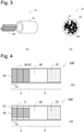
- Fig. 3(1) illustrates the outline of this embodiment.
- a reference sign 10r denotes the strip-shaped flavor generating sheet.
- the strip-shaped flavor generating sheets 10r are filled with the longitudinal direction aligned substantially in parallel to the longitudinal direction of the cylindrical container 12.
- Fig. 3(2) is a cross-sectional view of the segment 1s of this embodiment.
- the strip-shaped flavor generating sheet 10r may be subjected to the surface treatment.
- a production method disclosed in Japanese Patent Laid-Open No. 62-272962 is known, and the segment 1s of the present invention can also be produced by the method described in this publication.
- a reconstituted tobacco sheet is preferably used as a sheet material instead of a recycled tobacco material, and as the reconstituted tobacco sheet, a sheet obtained by a papermaking process, a slurry sheet, or a cast sheet is preferably used.
- a strip of a sheet material pulled out of a bobbin may be subjected to the surface treatment described in the above paragraph before being caused to pass through cutting means.
- the flavor generating sheet 10s can be prepared by a known method.
- the flavor generating sheet 10s can be prepared by a known method of, for example, a papermaking, slurry, or rolling method. Specifically, in employing the papermaking method, it can be produced by a method comprising the following steps: 1) A dried leaf tobacco raw material is coarsely crushed, and the resultant is separated into a water extract and a residue through extraction with water. 2) The water extract is concentrated by vacuum drying. 3) Pulp is added to the residue, and the resultant is fiberized with a refiner, followed by papermaking. 4) A concentrate of the water extract is added to a sheet resulting from the papermaking, and the resultant is dried to obtain a tobacco sheet.
- the shape of the flavor generating sheet 10s is not limited, and the principal surface of the sheet is preferably in a rectangular shape.
- the thickness is not limited, and in consideration of highly efficient heat exchange and the strength of a flavor generating segment, is preferably 200 to 600 ⁇ m.
- One side A of the flavor generating sheet 10s preferably has the same length as the length in the longitudinal direction of the cylindrical container 12.
- the length of the other side B of the flavor generating sheet 10s is appropriately adjusted, and in one embodiment, is 1 to 10 times as long as the length of A.
- the strip-shaped flavor generating sheet 10r can be prepared by cutting the flavor generating sheet 10s.
- a length a in the longitudinal direction of the strip-shaped flavor generating sheet 10r is preferably the same as the length in the longitudinal direction of the cylindrical container 12.
- a length b in the short direction of the strip-shaped flavor generating sheet 10r is appropriately adjusted, and in one embodiment, is about 0.4 to 3.0 mm, preferably 0.6 to 2.0 mm, and more preferably 0.8 to 1.5 mm.
- the flavor source 10 may include an aerosol source.
- An example of the aerosol source includes polyol such as glycerin, propylene glycol, or 1,3-butanediol.
- the amount of the aerosol source to be added is preferably 5 to 50% by weight, and more preferably 10 to 30% by weight based on a dry weight of the flavor source 10.
- the aerosol source included in the flavor source 10 is referred to also as the "internal aerosol source".
- the tobacco rod 1 is suitably used for the direct heating type flavor inhaler.
- the flavor source 10 for the indirect heating type flavor inhaler preferably does not include the internal aerosol source.
- the cylindrical container 12 is made of a known material.
- a side surface of the cylindrical container 12 is made of a material selected from the group consisting of paper, a resin, a metal, and a combination thereof.
- the cylindrical container 12 is preferably made of a resin from the viewpoint of handleability.
- the resin include polypropylene, polyethylene terephthalate, polyethylene, ABS, and a polylactic acid resin.
- the thickness of a side surface portion is not limited, and is preferably about 0.4 to 1.0 mm, more preferably about 0.6 to 0.8 mm, and further preferably about 0.7 mm.
- its side surface is preferably made of a laminate of paper with a resin film such as a polyethylene film, polyvinyl alcohol, or polylactic acid, a laminate of paper with a thin layer formed by coating a solution of a polysaccharide/mucopolysaccharide, such as alginic acid, carrageenan, carboxymethyl cellulose, xanthan gum, guar gum, pectin, mannose, glucuronic acid, locust bean gum, gellan gum, starch, oxidized starch, processed starch, hyaluronic acid, or chondroitin sulfate, a laminate of paper with a metal foil such as an aluminum foil, or cardboard.
- a resin film such as a polyethylene film, polyvinyl alcohol, or polylactic acid
- the number of layers in the laminate is not limited, and a three-layer structure of a paper layer/a resin layer (or a metal foil layer, or a polysaccharide/mucopolysaccharide layer)/a paper layer is preferably employed. Since the paper layer is exposed in such a laminate, it can be sufficiently adhered with a vinyl acetate adhesive or a hot melt adhesive when wound. At this point, sufficient peel strength (22.4 g to 28.0 g) can be attained, and adhesive peeling otherwise caused after winding can be reduced.
- An example of the paper includes Sandwich Laminate #85/S52 manufactured by Nippon Paper Papylia Co., Ltd. (thickness: 220 ⁇ m, basis weight: 85/52 gsm, stiffness: 145 cm 3 /100).
- the thickness of the resin layer is preferably 12 to 70 ⁇ m, and more preferably 17 to 20 ⁇ m.
- the cardboard has permeability of preferably less than 50 coresta units, more preferably less than 15 coresta units, and further preferably less than 1 coresta unit.
- the thickness is preferably 100 to 150 ⁇ m, and the basis weight is preferably about 80 to 150 gsm.
- the cardboard can be one containing 87.5% by weight of kraft pulp, 5% by weight of an inorganic filler, 0.5% by weight of starch, and about 7% by weight of moisture. Such cardboard is available from, for example, Julius Glatz GmbH.
- the side surface of the cylindrical container 12 has permeability of preferably less than 1 coresta unit, and more preferably 0 coresta unit.
- a coresta unit refers to air flow volume (cm 3 ) per cm 2 and per minute under a condition of 100 mm H 2 O.
- the permeability can be measured using an permeability meter PPM100 manufactured by FILTRONA, USA.
- One end or both ends of the cylindrical container 12 may be opened, or may be closed with retaining the permeability. If the end is closed, the end is preferably made of the above-described material.
- the dimension of the cylindrical container 12 is appropriately adjusted to attain the above-described dimension of the tobacco rod 1.
- the cylindrical container 12 may be continuous over a plurality of segments 1s.
- the direct heating type flavor inhaler refers to an article that generates a flavor by heating the flavor source 10.
- Fig. 4 illustrates one embodiment of the direct heating type flavor inhaler.
- a reference sign 100 denotes the direct heating type flavor inhaler
- the reference sign 1 denotes the tobacco rod
- a reference sign 2 denotes a mouthpiece
- a reference sign 20 denotes a cooling portion
- a reference sign 22 denotes a filter
- a reference sign 3 denotes a wrapper.
- the mouthpiece is not limited in the dimension, and preferably has the same width as the tobacco rod 1, and preferably has a length of 26 to 50 mm.
- the filter 22 is preferably made of a material usually used in this field, such as a cellulose acetate filter.
- the length of the filter 22 is preferably 12 to 60% of the whole length of the mouthpiece.
- the cooling portion 20 has a function to cool aerosol.
- the cooling portion 20 may be hollow, or may have a cooling element such as a polylactic acid film.
- the cooling portion 20 may be provided with ventilation.
- the length of the cooling member 20 is preferably 8 to 77% of the whole length of the mouthpiece 2.
- the wrapper 3 the laminate of paper with a resin film such as a polyethylene film, the laminate of paper with a thin film formed by drying a solution of a saccharide/polysaccharide, the laminate of paper with a metal foil such as an aluminum foil, the cardboard described above or the like can be used.
- the cylindrical container 12 may be elongated to also work as the wrapper 3 as illustrated in Fig. 4(1) .
- the wrapper 3 may be provided outside the cylindrical container 12 as illustrated in Fig. 4(2) .
- the cylindrical container 12 is preferably made of the resin or the cardboard.
- the direct heating type flavor inhaler is heated by a known heater.
- the heater is preferably capable of electrically heating the tobacco rod 1 to 200 to 400°C.
- the direct heating type flavor inhaler is classified into an internal heating type in which the heater is inserted into the tobacco rod 1, and an external heating type in which the heater is provided around the tobacco rod 1. In the present invention, the latter is preferred because the structure of the channels is not changed before and after the heater is installed.
- a combination of the direct heating type flavor inhaler and the heater is also referred to as a direct heating type flavor inhaling system.
- the indirect heating type flavor inhaler refers to an article that generates a flavor without directly heating the flavor source but generating aerosol from the aerosol source disposed on the upstream side to cause a flavor component from the flavor source to be carried on the aerosol.
- Fig. 5 illustrates an embodiment of the indirect heating type flavor inhaler.
- a reference sign 200 denotes an indirect heating type flavor inhaler
- a reference sign 1 denotes a tobacco rod
- a reference sign 1s denotes a segment
- a reference sign 3 denotes a wrapper
- a reference sign 4 denotes an atomizing portion
- a reference sign 5 denotes an external aerosol source
- a reference sign 7 denotes an outer frame.
- the external aerosol source 5 is disposed on the upstream side of the tobacco rod 1, and aerosol is generated by the atomizing portion 4.
- the atomizing portion 4 is preferably capable of electrically heating the external aerosol source 5 to about 200 to 300°C. Through this heating, the aerosol is generated, and the aerosol is introduced into the tobacco rod 1, passes therethrough while the flavor source is exposed to an atmosphere of 30 to 40°C, and carries the flavor component which is then inhaled by a user.
- a combination of the indirect heating type flavor inhaler and a power supply is also referred to as an indirect heating type flavor inhaling system.
- Known indirect heating type flavor inhaler and indirect heating type flavor inhaling system are disclosed in, for example, International Publication No. WO2016/075749 .
- Fig. 6 illustrates a preferable embodiment of the indirect heating type flavor inhaling system.
- a reference sign 210 denotes the indirect heating type flavor inhaling system
- a reference sign 203 denotes a power supply unit
- a reference sign 210 denotes a cartridge.
- the cartridge 201 is detachable from the power supply unit 203.
- the cartridge 201 includes the external aerosol source 5, the atomizing portion 4, and a passage 6.
- the tobacco rod 1 is housed in a space disposed at the mouthpiece end in the cartridge 201.
- the tobacco rod 1 is housed in the space within the cartridge 201 to constitute the indirect heating type flavor inhaler 200.
- the cartridge 201 may have a filter at the mouthpiece end.
- the external aerosol source 5 can be configured by causing the above-described aerosol source to be supported on a porous material such as a fiber filler.
- the length of the external aerosol source 5 is not limited, and is preferably 10 to 25 mm.
- the power supply unit 203 includes a power supply such as a battery, and atomizes the aerosol source without causing combustion.
- the outer frame 7 of the indirect heating type flavor inhaler can be a resin housing.
- the side wall of the cartridge 201 corresponds to the outer frame 7.
- the tobacco rod of the present invention can be used also for an ultrasonic vibration type flavor inhaler, that is, one application of the indirect heating type flavor inhaler.
- the ultrasonic vibration type flavor inhaler refers to a flavor inhaler employing a system in which an ultrasonic oscillator is used in the atomizing portion to generate aerosol by vibrating the external aerosol source.
- the tobacco rod 1 of the present invention is produced preferably through the following steps:
- a reference sign 1' denotes the precursor
- a reference sign Y denotes the longitudinal direction axis
- a reference sign Z denotes a cut position.
- the precursor can be prepared in the same manner as the segment 1s.
- the precursor 1' is cut in the direction vertical to the longitudinal direction.
- the precursor 1' is cut in the positions Z in Fig. 8 .
- Fig. 8 illustrates an embodiment in which the center segment is rotated in the circumferential direction by about 30 degrees.
- a tobacco sheet obtained by a papermaking process (thickness: 200 ⁇ m, basis weight: 71 g/m 2 , nicotine amount: 1.4% by weight) was treated with an alkaline aqueous solution of pH 9.6.
- the thus prepared flavor generating sheet was cut into a square shape having a side of 21 mm, and a weight of 310 mg.
- a polypropylene straw having a diameter of 8 mm, a wall thickness of 0.2 mm, and a length of 21 mm was provided.
- the cut flavor generating sheet was folded and filled within the straw to prepare a precursor.
- the precursor had a cross-section in a shape as illustrated in Fig. 2(1).
- the precursor was cut, vertically to the longitudinal direction, into three equal portions to obtain three segments.
- the center segment was rotated in the circumferential direction around a central axis in the longitudinal direction by 120 degrees. Thereafter, the three segments were connected to one another by winding these with one piece of tipping paper, and thus, a tobacco rod including three segments was produced.
- the indirect heating type flavor inhaling system illustrated in Fig. 6 was provided.
- the length of the cartridge 201 was 21 mm, which was the same as that of the tobacco rod 1.
- the system was used to perform machine smoking of 20 puffs.
- a sample was prepared in accordance with the humidity controlling/conditioning method for tobacco and tobacco products defined by ISO (the International Organization for Standardization) 3402: 1999 (Non Patent Literature).
- ISO the International Organization for Standardization
- a machine smoking method and a method for collecting a generated aerosol were performed in accordance with CORRESTA RECOMMENDED METHOD No.
- a Cambridge filter in which the aerosol had been trapped was collected to measure a nicotine amount by gas chromatography.
- a Cambridge filter is a flat circular glass fiber filter having a diameter of about 44 mm and a thickness of 1.5 mm, and is known to and widely used by those skilled in the art as a filter capable of trapping a particulate matter.
- the Cambridge filter is available from Cambridge Filter Japan, Ltd., Borgwalt (Catalog No. 8020 285 2) and the like.
- TPM total particle matter
- a precursor was prepared in the same manner as in Example 1. Subsequently, the precursor was cut into five equal portions to obtain five segments. The second and fourth segments were rotated in the circumferential direction around the central axis in the longitudinal direction by 72 degrees, and thus, a tobacco rod including five segments was prepared. This tobacco rod was evaluated in the same manner as in Example 1.
- a tobacco sheet obtained by a papermaking process which was the same as that used in Example 1, was provided. Subsequently, the resultant sheet was subjected to a surface treatment using a crimping roller. As the crimping roller, a chevron roller (60 degrees, 1 mm pitch) was used. In this manner, a flavor generating sheet was prepared. The flavor generating sheet was cut into a square shape having a side of 21 mm, and a weight of 310 mg. The thus cut sheet was used to produce a tobacco rod including five segments in the same manner as in Example 3, and the resultant was evaluated.
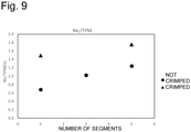
- Tobacco rods respectively including one and five segments were produced in the same manner as in Examples 1 and 3 except that the precursor was directly used as a tobacco rod without cutting, and the resultants were evaluated. Results are shown in Table 1 and Fig. 9 .
- the tobacco rods of the examples had higher values, than those of the comparative examples, of a ratio of the flavor component contained in the particulate matter of the aerosol generated from the tobacco rod. It is thus obvious that the tobacco rod of the present invention has an excellent volatilization property for a flavor component.
Landscapes
- Manufacture Of Tobacco Products (AREA)
- Cigarettes, Filters, And Manufacturing Of Filters (AREA)
Abstract
Description
- The present invention relates to a tobacco rod for a flavor inhaler, and more particularly, it relates to a tobacco rod for a direct heating type or indirect heating type flavor inhaler.
- A direct heating type flavor inhaler and an indirect heating type flavor inhaler have been developed to be used instead of a conventional combustion type smoking article.
PTL 1 discloses a heating type smoking article including a gathered or crimped tobacco material sheet. - PTL 1:
Japanese Patent No. 6017546 - A flavor source of a direct heating type flavor inhaler is heated at a lower temperature than a conventional combustion type tobacco, and a flavor source of an indirect heating type flavor inhaler is not directly heated. Therefore, in the direct heating type flavor inhaler and the indirect heating type flavor inhaler, a flavor component does not have a high volatilization property as compared with that of the conventional combustion type tobacco. In consideration of these circumstances, an object of the present invention is to provide a tobacco rod for a flavor inhaler having high volatilization efficiency of a flavor component.
- The present inventors made earnest studies to find that the above-described problem can be solved by a tobacco rod in which a plurality of segments are connected to one another in such a manner that channels of the segments are discontinuous. Specifically, the above-described problem is solved by the following present invention.
- A tobacco rod for a flavor inhaler, comprising a plurality of rod-shaped segments connected to one another, in which each of the segments includes a cylindrical container and a flavor source including tobacco filled in the cylindrical container, the flavor source being filled in such a manner as to form, over a longitudinal direction, a channel for causing a flavor component to pass therethrough, and the channels of the segments are discontinuously connected at the connecting portion.
- The tobacco rod according to the
embodiment 1, wherein the tobacco rod is for use in a direct heating type or indirect heating type flavor inhaler. - The tobacco rod according to any one of the
embodiments 2 to 4, in which the flavor source comprises a surface-treated flavor generating sheet. - The tobacco rod according to the
embodiment - The tobacco rod according to any one of the
embodiments 2 to 4, in which the side surface of the cylindrical container has a multilayer structure. - The tobacco rod according to any one of the
embodiments 2 to 5, in which the side surface of the cylindrical container has an permeability of less than 1 coresta unit. - The tobacco rod according to any one of the
embodiments 2 to 6, in which the flavor source comprises a plurality of strip-shaped flavor generating sheets, and a longitudinal direction of the sheets is substantially parallel to the longitudinal direction of the cylindrical container. - The tobacco rod according to any one of the
embodiments 2 to 7, in which the flavor source comprises an aerosol source that generates aerosol. - A method for producing the tobacco rod according to any one of the
embodiments 1 to 8, including: a step of providing a precursor that includes a cylindrical container and a flavor source including tobacco filled in the cylindrical container, the flavor source being filled in such a manner as to form, over a longitudinal direction, a channel for causing a flavor component to pass therethrough; a step of preparing two or more of the segments by cutting the precursor in a direction vertical to the longitudinal direction; and a step of rotating one or more of the segments in a circumferential direction around a longitudinal direction axis. - A direct heating type or indirect heating type flavor inhaler, comprising the tobacco rod according to any one of the
embodiments 1 to 8. - The flavor inhaler according to the
embodiment 10, further comprising an aerosol source that generates aerosol on an upstream side of the tobacco rod. - An ultrasonic vibration type flavor inhaler, comprising the tobacco rod according to the
embodiment 1. - The present invention can provide a tobacco rod for a flavor inhaler having high volatilization efficiency of a flavor component.
-
-
Fig. 1 is a schematic diagram of a tobacco rod. -
Fig. 2 is a cross-sectional view of a segment according to one embodiment. -
Fig. 3 illustrates a schematic diagram and a cross-sectional view of the segment according to another embodiment. -
Fig. 4 is a conceptual diagram of a direct heating type flavor inhaler. -
Fig. 5 is a conceptual diagram of an indirect heating type flavor inhaler. -
Fig. 6 is a conceptual diagram of an indirect heating type flavor inhaling system according to one embodiment. -
Fig. 7 is a cross-sectional view of a cartridge according to one embodiment. -
Fig. 8 is a conceptual diagram illustrating a method for producing a tobacco rod. -
Fig. 9 is a diagram of correlation between the number of segments and a volatilization property of a flavor component. - The present invention will now be described in detail. In the present invention, the term "X to Y" embraces end values of X and Y.
- A tobacco rod refers to a cylindrical member that generates a flavor. A side on a mouthpiece end of the tobacco rod is referred to as the "downstream" side, and the other side is referred to as the "upstream" side. The outline of the tobacco rod is illustrated in
Fig. 1. Fig. 1 is a perspective view of the tobacco rod. In the drawing, areference sign 1 denotes the tobacco rod, areference sign 1s denotes a segment included in thetobacco rod 1, and areference sign 1c denotes a channel for causing a flavor component to pass therethrough over a longitudinal direction. As illustrated in this drawing, thechannels 1c are connected to each other discontinuously at a connecting surface between thesegments 1s. The term "connected discontinuously" means that the channels are connected to overlap with each other not wholly but partially. Although onechannel 1c in eachsegment 1s is illustrated in this drawing for ease of understanding, there can be present a plurality ofchannels 1c. When a plurality ofchannels 1c are present, one or more discontinuously connected channels may be formed over the longitudinal direction of thetobacco rod 1. Besides, the channels provided over the longitudinal direction may have one or more discontinuously connected sites. For example, when three rod-shaped segments are present, either a connecting portion between the first and second segments or a connecting portion between the second and third segments may have a discontinuously connected site. Since such channels are provided in the present invention, a time when aerosol stays in thetobacco rod 1 can be extended, and hence, volatilization efficiency of a flavor component can be improved. An example of a substance to be used for comparison of a volatilization property of a flavor component includes nicotine. - The cross-sectional shape of the
tobacco rod 1 is not limited, and can be a circular, elliptical, polygonal, or rounded polygonal shape. The size of the cross-sectional shape of thetobacco rod 1 is not limited, and the maximum length (hereinafter also referred to as the "width") is preferably 1 mm or more, and more preferably 3 mm or more. The upper limit is preferably 9 mm or less, and more preferably 7 mm or less. The length of thetobacco rod 1 is preferably 40 mm or less, and more preferably 25 mm or less. The lower limit is preferably 1 mm or more, and more preferably 5 mm or more. The length of thesegment 1s can be appropriately adjusted depending on the length of thetobacco rod 1 and the number of segments. - The
segment 1s comprises aflavor source 10 including tobacco. Theflavor source 10 including tobacco (hereinafter also simply referred to as the "flavor source") forms a channel through which aerosol flows over the longitudinal direction of thesegment 1s. Therefore, theflavor source 10 including tobacco is preferably a flavor generating sheet. The flavor generating sheet can be a sheet in which a component capable of generating a flavor is supported on a sheet substrate, or a sheet made of a material that generates a flavor. Examples of the component capable of generating a flavor include a smoking flavor component contained in a tobacco raw material, and a perfume component such as menthol. The sheet substrate can be, for example, a tobacco material such as a compressed tobacco pellet or a tobacco powder, and is preferably a tobacco material. In other words, the flavor generating sheet may contain a tobacco-derived material in either the sheet substrate or the component capable of generating a flavor, and in one embodiment, a tobacco sheet in which a component capable of generating a flavor if necessary is supported on a substrate sheet of a tobacco material is preferably used. - The
flavor source 10 is filled in acylindrical container 12 described below in such a manner as to form channel voids over the longitudinal direction.Fig. 2 is a cross-sectional view of thesegment 1s in which aflavor generating sheet 10s is folded to be filled in thecylindrical container 12 as theflavor source 10. Fig. 2(1) illustrates an embodiment in which theflavor generating sheet 10s not having been subjected to a surface treatment is filled, and Fig. 2(2) illustrates an embodiment in which theflavor generating sheet 10s having been subjected to a surface treatment such as crimping is filled. In this case, the number of flavor generating sheets to be filled is not limited, can be 1 to 3, and is preferably 1 from the viewpoint of manufacturability. - The amount of the
flavor source 10 to be filled is appropriately adjusted, and in one embodiment, the amount is preferably 40 to 90% by volume based on the volume of thecylindrical container 12. A more preferable lower limit is 50% by volume or more, 55% by volume or more, or 60% by volume or more, and a more preferable upper limit is 60% by volume or less, 65% by volume or less, 70% by volume or less, 80% by volume or less, or 90% by volume or less. When a plurality ofchannels 1c are present, the channels may have substantially uniform cross-sectional areas, or there may be one or more channels having larger cross-sectional areas than the others. In the later embodiment, it is preferable that the channels having the larger cross-sectional areas are discontinuously connected. - If the
flavor generating sheet 10s is used as theflavor source 10, at least one surface of the sheet is preferably subjected to a surface treatment. The surface treatment refers to a process for forming a plurality of irregularities on the front surface or the rear surface of theflavor generating sheet 10s. The surface treatment is not especially limited, and crimping process, embossing process, debossing process, half cutting process, or the like can be performed. The crimping process is a process for forming wrinkles in the sheet. For example, when theflavor generating sheet 10s is allowed to pass between a pair of rollers each having a plurality of projections on the surface, the crimping process can be performed by forming wrinkles extending orthogonally to a sheet conveyance direction on both the front surface and the rear surface of theflavor generating sheet 10s. The thus formed projections extend orthogonally to the sheet conveyance direction. A pitch between apexes of the projections provided on the rollers is preferably 0.5 to 2.0 mm. Besides, an apex angle is preferably 30 to 70 degrees. The embossing process and the debossing process refer to a process for forming recesses on one surface or both surfaces of the sheet by pressing a pointed working tool against the sheet, and the half cutting process refers to a process for forming, on one surface or both surfaces of the sheet, a notch having a depth sufficiently small not to cut the sheet, preferably a depth equal to or smaller than a half of the thickness of the sheet. - Alternatively, a plurality of strip-shaped flavor generating sheets may be used as the
flavor source 10. A strip-shaped sheet refers to a sheet having a length in a short direction, on a principal surface, smaller than the cross-sectional dimension of thecylindrical container 12.Fig. 3(1) illustrates the outline of this embodiment. In this drawing, areference sign 10r denotes the strip-shaped flavor generating sheet. The strip-shapedflavor generating sheets 10r are filled with the longitudinal direction aligned substantially in parallel to the longitudinal direction of thecylindrical container 12.Fig. 3(2) is a cross-sectional view of thesegment 1s of this embodiment. The strip-shapedflavor generating sheet 10r may be subjected to the surface treatment. - As a method for producing the tobacco rod, a production method disclosed in
Japanese Patent Laid-Open No. 62-272962 segment 1s of the present invention can also be produced by the method described in this publication. In the present invention, however, a reconstituted tobacco sheet is preferably used as a sheet material instead of a recycled tobacco material, and as the reconstituted tobacco sheet, a sheet obtained by a papermaking process, a slurry sheet, or a cast sheet is preferably used. Besides, a strip of a sheet material pulled out of a bobbin may be subjected to the surface treatment described in the above paragraph before being caused to pass through cutting means. - The
flavor generating sheet 10s can be prepared by a known method. Theflavor generating sheet 10s can be prepared by a known method of, for example, a papermaking, slurry, or rolling method. Specifically, in employing the papermaking method, it can be produced by a method comprising the following steps: 1) A dried leaf tobacco raw material is coarsely crushed, and the resultant is separated into a water extract and a residue through extraction with water. 2) The water extract is concentrated by vacuum drying. 3) Pulp is added to the residue, and the resultant is fiberized with a refiner, followed by papermaking. 4) A concentrate of the water extract is added to a sheet resulting from the papermaking, and the resultant is dried to obtain a tobacco sheet. - The shape of the
flavor generating sheet 10s is not limited, and the principal surface of the sheet is preferably in a rectangular shape. The thickness is not limited, and in consideration of highly efficient heat exchange and the strength of a flavor generating segment, is preferably 200 to 600 µm. One side A of theflavor generating sheet 10s preferably has the same length as the length in the longitudinal direction of thecylindrical container 12. The length of the other side B of theflavor generating sheet 10s is appropriately adjusted, and in one embodiment, is 1 to 10 times as long as the length of A. - The strip-shaped
flavor generating sheet 10r can be prepared by cutting theflavor generating sheet 10s. A length a in the longitudinal direction of the strip-shapedflavor generating sheet 10r is preferably the same as the length in the longitudinal direction of thecylindrical container 12. A length b in the short direction of the strip-shapedflavor generating sheet 10r is appropriately adjusted, and in one embodiment, is about 0.4 to 3.0 mm, preferably 0.6 to 2.0 mm, and more preferably 0.8 to 1.5 mm. - The
flavor source 10 may include an aerosol source. An example of the aerosol source includes polyol such as glycerin, propylene glycol, or 1,3-butanediol. The amount of the aerosol source to be added is preferably 5 to 50% by weight, and more preferably 10 to 30% by weight based on a dry weight of theflavor source 10. The aerosol source included in theflavor source 10 is referred to also as the "internal aerosol source". When containing the internal aerosol source, thetobacco rod 1 is suitably used for the direct heating type flavor inhaler. As described below, theflavor source 10 for the indirect heating type flavor inhaler preferably does not include the internal aerosol source. - The
cylindrical container 12 is made of a known material. For example, a side surface of thecylindrical container 12 is made of a material selected from the group consisting of paper, a resin, a metal, and a combination thereof. When used for the indirect heating type flavor inhaler, thecylindrical container 12 is preferably made of a resin from the viewpoint of handleability. Examples of the resin include polypropylene, polyethylene terephthalate, polyethylene, ABS, and a polylactic acid resin. The thickness of a side surface portion is not limited, and is preferably about 0.4 to 1.0 mm, more preferably about 0.6 to 0.8 mm, and further preferably about 0.7 mm. - When the
cylindrical container 12 is used for the indirect heating type flavor inhaler, its side surface is preferably made of a laminate of paper with a resin film such as a polyethylene film, polyvinyl alcohol, or polylactic acid, a laminate of paper with a thin layer formed by coating a solution of a polysaccharide/mucopolysaccharide, such as alginic acid, carrageenan, carboxymethyl cellulose, xanthan gum, guar gum, pectin, mannose, glucuronic acid, locust bean gum, gellan gum, starch, oxidized starch, processed starch, hyaluronic acid, or chondroitin sulfate, a laminate of paper with a metal foil such as an aluminum foil, or cardboard. The number of layers in the laminate is not limited, and a three-layer structure of a paper layer/a resin layer (or a metal foil layer, or a polysaccharide/mucopolysaccharide layer)/a paper layer is preferably employed. Since the paper layer is exposed in such a laminate, it can be sufficiently adhered with a vinyl acetate adhesive or a hot melt adhesive when wound. At this point, sufficient peel strength (22.4 g to 28.0 g) can be attained, and adhesive peeling otherwise caused after winding can be reduced. An example of the paper includes Sandwich Laminate #85/S52 manufactured by Nippon Paper Papylia Co., Ltd. (thickness: 220 µm, basis weight: 85/52 gsm, stiffness: 145 cm3/100). The thickness of the resin layer is preferably 12 to 70 µm, and more preferably 17 to 20 µm. - The cardboard has permeability of preferably less than 50 coresta units, more preferably less than 15 coresta units, and further preferably less than 1 coresta unit. The thickness is preferably 100 to 150 µm, and the basis weight is preferably about 80 to 150 gsm. The cardboard can be one containing 87.5% by weight of kraft pulp, 5% by weight of an inorganic filler, 0.5% by weight of starch, and about 7% by weight of moisture. Such cardboard is available from, for example, Julius Glatz GmbH.
- From the viewpoint of satisfactorily improving the volatilization property of the flavor component, the side surface of the
cylindrical container 12 has permeability of preferably less than 1 coresta unit, and more preferably 0 coresta unit. A coresta unit refers to air flow volume (cm3) per cm2 and per minute under a condition of 100 mm H2O. The permeability can be measured using an permeability meter PPM100 manufactured by FILTRONA, USA. - One end or both ends of the
cylindrical container 12 may be opened, or may be closed with retaining the permeability. If the end is closed, the end is preferably made of the above-described material. The dimension of thecylindrical container 12 is appropriately adjusted to attain the above-described dimension of thetobacco rod 1. Thecylindrical container 12 may be continuous over a plurality ofsegments 1s. - The direct heating type flavor inhaler refers to an article that generates a flavor by heating the
flavor source 10.Fig. 4 illustrates one embodiment of the direct heating type flavor inhaler. In this drawing, areference sign 100 denotes the direct heating type flavor inhaler, thereference sign 1 denotes the tobacco rod, areference sign 2 denotes a mouthpiece, areference sign 20 denotes a cooling portion, areference sign 22 denotes a filter, and areference sign 3 denotes a wrapper. - The mouthpiece is not limited in the dimension, and preferably has the same width as the
tobacco rod 1, and preferably has a length of 26 to 50 mm. Thefilter 22 is preferably made of a material usually used in this field, such as a cellulose acetate filter. The length of thefilter 22 is preferably 12 to 60% of the whole length of the mouthpiece. The coolingportion 20 has a function to cool aerosol. The coolingportion 20 may be hollow, or may have a cooling element such as a polylactic acid film. The coolingportion 20 may be provided with ventilation. The length of the coolingmember 20 is preferably 8 to 77% of the whole length of themouthpiece 2. - As the
wrapper 3, the laminate of paper with a resin film such as a polyethylene film, the laminate of paper with a thin film formed by drying a solution of a saccharide/polysaccharide, the laminate of paper with a metal foil such as an aluminum foil, the cardboard described above or the like can be used. In other words, thecylindrical container 12 may be elongated to also work as thewrapper 3 as illustrated inFig. 4(1) . In another embodiment, thewrapper 3 may be provided outside thecylindrical container 12 as illustrated inFig. 4(2) . In this embodiment, thecylindrical container 12 is preferably made of the resin or the cardboard. - The direct heating type flavor inhaler is heated by a known heater. The heater is preferably capable of electrically heating the
tobacco rod 1 to 200 to 400°C. In general, the direct heating type flavor inhaler is classified into an internal heating type in which the heater is inserted into thetobacco rod 1, and an external heating type in which the heater is provided around thetobacco rod 1. In the present invention, the latter is preferred because the structure of the channels is not changed before and after the heater is installed. A combination of the direct heating type flavor inhaler and the heater is also referred to as a direct heating type flavor inhaling system. - The indirect heating type flavor inhaler refers to an article that generates a flavor without directly heating the flavor source but generating aerosol from the aerosol source disposed on the upstream side to cause a flavor component from the flavor source to be carried on the aerosol.
Fig. 5 illustrates an embodiment of the indirect heating type flavor inhaler. In the drawing, areference sign 200 denotes an indirect heating type flavor inhaler, areference sign 1 denotes a tobacco rod, areference sign 1s denotes a segment, areference sign 3 denotes a wrapper, areference sign 4 denotes an atomizing portion, areference sign 5 denotes an external aerosol source, and areference sign 7 denotes an outer frame. Theexternal aerosol source 5 is disposed on the upstream side of thetobacco rod 1, and aerosol is generated by the atomizingportion 4. The atomizingportion 4 is preferably capable of electrically heating theexternal aerosol source 5 to about 200 to 300°C. Through this heating, the aerosol is generated, and the aerosol is introduced into thetobacco rod 1, passes therethrough while the flavor source is exposed to an atmosphere of 30 to 40°C, and carries the flavor component which is then inhaled by a user. A combination of the indirect heating type flavor inhaler and a power supply is also referred to as an indirect heating type flavor inhaling system. Known indirect heating type flavor inhaler and indirect heating type flavor inhaling system are disclosed in, for example, International Publication No.WO2016/075749 . -
Fig. 6 illustrates a preferable embodiment of the indirect heating type flavor inhaling system. In this drawing, areference sign 210 denotes the indirect heating type flavor inhaling system, areference sign 203 denotes a power supply unit, and areference sign 210 denotes a cartridge. Thecartridge 201 is detachable from thepower supply unit 203. As illustrated inFig. 7 , thecartridge 201 includes theexternal aerosol source 5, the atomizingportion 4, and apassage 6. Thetobacco rod 1 is housed in a space disposed at the mouthpiece end in thecartridge 201. Thetobacco rod 1 is housed in the space within thecartridge 201 to constitute the indirect heatingtype flavor inhaler 200. Thecartridge 201 may have a filter at the mouthpiece end. - The
external aerosol source 5 can be configured by causing the above-described aerosol source to be supported on a porous material such as a fiber filler. The length of theexternal aerosol source 5 is not limited, and is preferably 10 to 25 mm. Thepower supply unit 203 includes a power supply such as a battery, and atomizes the aerosol source without causing combustion. - The
outer frame 7 of the indirect heating type flavor inhaler can be a resin housing. In the embodiment shown inFig. 6 , the side wall of thecartridge 201 corresponds to theouter frame 7. - Besides, the tobacco rod of the present invention can be used also for an ultrasonic vibration type flavor inhaler, that is, one application of the indirect heating type flavor inhaler. The ultrasonic vibration type flavor inhaler refers to a flavor inhaler employing a system in which an ultrasonic oscillator is used in the atomizing portion to generate aerosol by vibrating the external aerosol source.
- The
tobacco rod 1 of the present invention is produced preferably through the following steps: - Step 1: A precursor comprises a cylindrical container and a flavor source including tobacco filled in the cylindrical container is provided, the flavor source being filled in such a manner as to form, over the longitudinal direction, channels for causing a flavor component to pass therethrough.
- Step 2: The precursor is cut in a direction vertical to the longitudinal direction to prepare two or more of the segments described above.
- Step 3: One or more of the segments are rotated in a circumferential direction around a longitudinal direction axis.
- The outline of the production method is illustrated in
Fig. 8 . InFig. 8 , a reference sign 1' denotes the precursor, a reference sign Y denotes the longitudinal direction axis, and a reference sign Z denotes a cut position. - The precursor can be prepared in the same manner as the
segment 1s. - In this step, the precursor 1' is cut in the direction vertical to the longitudinal direction. For example, the precursor 1' is cut in the positions Z in
Fig. 8 . - In this step, one or more of the segments are rotated in the circumferential direction around the longitudinal direction axis. The longitudinal direction axis refers to an axis passing through the centers of a front edge surface and a rear edge surface. The angle of the rotation is not limited as long as discontinuously connected channels can be formed. For example,
Fig. 8 illustrates an embodiment in which the center segment is rotated in the circumferential direction by about 30 degrees. - A tobacco sheet obtained by a papermaking process (thickness: 200 µm, basis weight: 71 g/m2, nicotine amount: 1.4% by weight) was treated with an alkaline aqueous solution of pH 9.6. The thus prepared flavor generating sheet was cut into a square shape having a side of 21 mm, and a weight of 310 mg.
- As a cylindrical container, a polypropylene straw having a diameter of 8 mm, a wall thickness of 0.2 mm, and a length of 21 mm was provided. The cut flavor generating sheet was folded and filled within the straw to prepare a precursor. The precursor had a cross-section in a shape as illustrated in Fig. 2(1). Subsequently, the precursor was cut, vertically to the longitudinal direction, into three equal portions to obtain three segments. The center segment was rotated in the circumferential direction around a central axis in the longitudinal direction by 120 degrees. Thereafter, the three segments were connected to one another by winding these with one piece of tipping paper, and thus, a tobacco rod including three segments was produced.
- Referring to the description of
International Publication No. WO2016/075749 , the indirect heating type flavor inhaling system illustrated inFig. 6 was provided. The length of thecartridge 201 was 21 mm, which was the same as that of thetobacco rod 1. The system was used to perform machine smoking of 20 puffs. A sample was prepared in accordance with the humidity controlling/conditioning method for tobacco and tobacco products defined by ISO (the International Organization for Standardization) 3402: 1999 (Non Patent Literature). A machine smoking method and a method for collecting a generated aerosol were performed in accordance with CORRESTA RECOMMENDED METHOD No. 81 "ROUTINE ANALYTICAL MACHINE FOR E-CIGARETTE AEROSOL GENERATION AND COLLECTION - DEFINITIONS AND STANDARD". A Cambridge filter in which the aerosol had been trapped was collected to measure a nicotine amount by gas chromatography. A Cambridge filter is a flat circular glass fiber filter having a diameter of about 44 mm and a thickness of 1.5 mm, and is known to and widely used by those skilled in the art as a filter capable of trapping a particulate matter. The Cambridge filter is available from Cambridge Filter Japan, Ltd., Borgwalt (Catalog No. 8020 285 2) and the like. As a representative of flavor components contained in the particulate matter (total particle matter, hereinafter referred to as the "TPM") of the thus trapped aerosol, nicotine was analyzed to obtain a nicotine amount in the TPM. Quantitative determination of nicotine was performed by a method commonly employed by those skilled in the art. - A precursor was prepared in the same manner as in Example 1. Subsequently, the precursor was cut into five equal portions to obtain five segments. The second and fourth segments were rotated in the circumferential direction around the central axis in the longitudinal direction by 72 degrees, and thus, a tobacco rod including five segments was prepared. This tobacco rod was evaluated in the same manner as in Example 1.
- A tobacco sheet obtained by a papermaking process, which was the same as that used in Example 1, was provided. Subsequently, the resultant sheet was subjected to a surface treatment using a crimping roller. As the crimping roller, a chevron roller (60 degrees, 1 mm pitch) was used. In this manner, a flavor generating sheet was prepared. The flavor generating sheet was cut into a square shape having a side of 21 mm, and a weight of 310 mg. The thus cut sheet was used to produce a tobacco rod including five segments in the same manner as in Example 3, and the resultant was evaluated.
- Tobacco rods respectively including one and five segments were produced in the same manner as in Examples 1 and 3 except that the precursor was directly used as a tobacco rod without cutting, and the resultants were evaluated. Results are shown in Table 1 and
Fig. 9 .[Table 1] Number of Segments Nic/TPM mg/20 puff not crimped crimped Comparative Example 1 1 0.68 Example 1 3 1.02 Example 2 5 1.24 Comparative Example 2 1 1.49 Example 3 5 1.75 - As shown in Table 1, the tobacco rods of the examples had higher values, than those of the comparative examples, of a ratio of the flavor component contained in the particulate matter of the aerosol generated from the tobacco rod. It is thus obvious that the tobacco rod of the present invention has an excellent volatilization property for a flavor component.
-
- 1 tobacco rod
- 1s segment
- 1c channel
- 10 flavor source including tobacco
- 10s flavor generating sheet
- 10r strip-shaped flavor generating sheet
- 12 cylindrical container
- 100 direct heating type flavor inhaler
- 2 mouthpiece
- 20 cooling portion
- 22 filter
- 3 wrapper
- 200 indirect heating type flavor inhaler
- 210 indirect heating type flavor inhaling system
- 201 cartridge
- 4 atomizing portion
- 5 external aerosol source
- 6 passage
- 7 outer frame
- 203 power supply unit
- 1' precursor
- Y longitudinal direction axis
Z cut position
Claims (12)
- A tobacco rod for a flavor inhaler, comprising a plurality of rod-shaped segments connected to one another,wherein each of the segments includes a cylindrical container and a flavor source including tobacco filled in the cylindrical container, the flavor source being filled in such a manner as to form, over a longitudinal direction, a channel for causing a flavor component to pass therethrough, andthe channels of the segments are discontinuously connected at the connecting portion.
- The tobacco rod according to claim 1, wherein the tobacco rod is for use in a direct heating type or indirect heating type flavor inhaler.
- The tobacco rod according to any one of claims 2 to 4, wherein the flavor source comprises a surface-treated flavor generating sheet.
- The tobacco rod according to claim 2 or 3, wherein a side surface of the cylindrical container is made of a material selected from the group consisting of paper, a resin, a metal, and a combination thereof.
- The tobacco rod according to any one of claims 2 to 4, wherein the side surface of the cylindrical container has a multilayer structure.
- The tobacco rod according to any one of claims 2 to 5, wherein the side surface of the cylindrical container has a permeability of less than 1 coresta unit.
- The tobacco rod according to any one of claims 2 to 6, wherein the flavor source comprises a plurality of strip-shaped flavor generating sheets, and a longitudinal direction of the sheets is substantially parallel to the longitudinal direction of the cylindrical container.
- The tobacco rod according to any one of claims 2 to 7, wherein the flavor source comprises an aerosol source that generates aerosol.
- A method for producing the tobacco rod according to any one of claims 1 to 8, comprising:a step of providing a precursor including a cylindrical container and a flavor source including tobacco filled in the cylindrical container, the flavor source being filled in such a manner as to form, over a longitudinal direction, a channel for causing a flavor component to pass therethrough;a step of preparing two or more of the segments by cutting the precursor in a direction vertical to the longitudinal direction; anda step of rotating one or more of the segments in a circumferential direction around a longitudinal direction axis.
- A direct heating type or indirect heating type flavor inhaler, comprising the tobacco rod according to any one of claims 1 to 8.
- The flavor inhaler according to claim 10, further comprising an aerosol source that generates aerosol on an upstream side of the tobacco rod.
- An ultrasonic vibration type flavor inhaler, comprising the tobacco rod according to claim 1.
Applications Claiming Priority (1)
| Application Number | Priority Date | Filing Date | Title |
|---|---|---|---|
| PCT/JP2019/019659 WO2020234916A1 (en) | 2019-05-17 | 2019-05-17 | Tobacco rod for flavor inhaler |
Publications (4)
| Publication Number | Publication Date |
|---|---|
| EP3970537A1 true EP3970537A1 (en) | 2022-03-23 |
| EP3970537A4 EP3970537A4 (en) | 2023-01-04 |
| EP3970537C0 EP3970537C0 (en) | 2026-03-18 |
| EP3970537B1 EP3970537B1 (en) | 2026-03-18 |
Family
ID=73459222
Family Applications (1)
| Application Number | Title | Priority Date | Filing Date |
|---|---|---|---|
| EP19930112.8A Active EP3970537B1 (en) | 2019-05-17 | 2019-05-17 | Tobacco rod for flavor inhaler |
Country Status (7)
| Country | Link |
|---|---|
| US (2) | US20220071277A1 (en) |
| EP (1) | EP3970537B1 (en) |
| JP (2) | JP7595005B2 (en) |
| CN (1) | CN113840546A (en) |
| PL (1) | PL3970537T3 (en) |
| TW (1) | TW202042678A (en) |
| WO (1) | WO2020234916A1 (en) |
Families Citing this family (12)
| Publication number | Priority date | Publication date | Assignee | Title |
|---|---|---|---|---|
| KR102682158B1 (en) * | 2021-04-07 | 2024-07-04 | 주식회사 케이티앤지 | Aerosol generating article and aerosol generating device receving the same |
| KR102713416B1 (en) * | 2021-05-14 | 2024-10-02 | 주식회사 케이티앤지 | Aerosol generating article and aerosol generating device having the same |
| JP7312918B2 (en) * | 2021-06-28 | 2023-07-21 | 日本たばこ産業株式会社 | Manufacturing method of cartridge for flavor inhaler |
| WO2023188374A1 (en) * | 2022-03-31 | 2023-10-05 | 日本たばこ産業株式会社 | Atomization unit and method for manufacturing same, and inhalation device |
| WO2023188372A1 (en) * | 2022-03-31 | 2023-10-05 | 日本たばこ産業株式会社 | Atomization unit and method for manufacturing same, and inhalation device |
| WO2023188377A1 (en) * | 2022-03-31 | 2023-10-05 | 日本たばこ産業株式会社 | Atomization unit, method for manufacturing same, and inhalation tool |
| WO2023188375A1 (en) * | 2022-03-31 | 2023-10-05 | 日本たばこ産業株式会社 | Atomizing unit and method for manufacturing same, and inhaler |
| WO2023188373A1 (en) * | 2022-03-31 | 2023-10-05 | 日本たばこ産業株式会社 | Atomization unit, production method therefor, and inhalation device |
| WO2023188376A1 (en) * | 2022-03-31 | 2023-10-05 | 日本たばこ産業株式会社 | Atomization unit, method for manufacturing same, and inhalation apparatus |
| CN118512031A (en) * | 2023-02-20 | 2024-08-20 | 思摩尔国际控股有限公司 | An aerosol generating substrate and an aerosol generating product |
| WO2025229902A1 (en) * | 2024-04-30 | 2025-11-06 | 日本たばこ産業株式会社 | Aerosol-generating segment and aerosol-generating article |
| CN118787128B (en) * | 2024-08-26 | 2026-07-31 | 浙江中烟工业有限责任公司 | Method for improving richness of aroma of middle and rear sections of cigars |
Family Cites Families (21)
| Publication number | Priority date | Publication date | Assignee | Title |
|---|---|---|---|---|
| US4416295A (en) * | 1980-10-17 | 1983-11-22 | Union Camp Corporation | Smoking-material rods and a method of making such rods |
| JPS6017546B2 (en) | 1982-01-14 | 1985-05-04 | 航空宇宙技術研究所長 | How to extinguish a fuel tank fire |
| US4889143A (en) * | 1986-05-14 | 1989-12-26 | R. J. Reynolds Tobacco Company | Cigarette rods and filters containing strands provided from sheet-like materials |
| US5074321A (en) * | 1989-09-29 | 1991-12-24 | R. J. Reynolds Tobacco Company | Cigarette |
| US6615840B1 (en) * | 2002-02-15 | 2003-09-09 | Philip Morris Incorporated | Electrical smoking system and method |
| KR20080059548A (en) * | 2006-08-08 | 2008-06-30 | 심용석 | Tobacco with a constant tobacco taste. |
| CA2712412C (en) * | 2008-06-27 | 2016-11-29 | Olig Ag | Smoke-free cigarette |
| GB0818810D0 (en) * | 2008-10-14 | 2008-11-19 | British American Tobacco Co | Smoking article |
| WO2010113702A1 (en) * | 2009-04-03 | 2010-10-07 | 日本たばこ産業株式会社 | Sheet for non-combustion type smoking article, non-combustion type smoking article, and method for producing same |
| EP2550877B1 (en) * | 2010-03-26 | 2020-06-17 | Japan Tobacco Inc. | Cigarette with increased volatile-flavor delivery |
| MX358027B (en) * | 2011-05-31 | 2018-08-01 | Philip Morris Products Sa | Rods for use in smoking articles. |
| UA111624C2 (en) * | 2011-10-07 | 2016-05-25 | Філіп Морріс Продактс С.А. | MULTI-SECTION SMOKING PRODUCT |
| WO2014016961A1 (en) * | 2012-07-27 | 2014-01-30 | 日本たばこ産業株式会社 | Smoking article |
| PT3136881T (en) * | 2014-08-13 | 2018-01-04 | Philip Morris Products Sa | Method of making a rod for use as an aerosol-forming substrate having controlled porosity distribution |
| CN107072311B (en) * | 2014-11-10 | 2021-01-05 | 日本烟草产业株式会社 | Non-combustion type fragrance extractor |
| CN107072310B (en) * | 2014-11-10 | 2020-08-04 | 日本烟草产业株式会社 | Cartridges and non-combustible aroma extractors |
| KR102836943B1 (en) * | 2015-09-30 | 2025-07-22 | 필립모리스 프로덕츠 에스.에이. | Smoking articles with reduced side-effects |
| GB201705888D0 (en) * | 2017-04-12 | 2017-05-24 | British American Tobacco Investments Ltd | Apparatus for volatilising smokable material and a smoking article |
| WO2018235241A1 (en) * | 2017-06-22 | 2018-12-27 | 日本たばこ産業株式会社 | Flavor generation segment, and flavor generation article and flavor suction system comprising the same |
| GB201712380D0 (en) * | 2017-08-01 | 2017-09-13 | British American Tobacco Investments Ltd | A modular tobacco industry product |
| JP6280287B1 (en) * | 2017-11-02 | 2018-02-14 | 株式会社 東亜産業 | Electronic cigarette cartridge using tobacco plant or non-tobacco plant and supporting member thereof |
-
2019
- 2019-05-17 EP EP19930112.8A patent/EP3970537B1/en active Active
- 2019-05-17 CN CN201980096518.0A patent/CN113840546A/en active Pending
- 2019-05-17 PL PL19930112.8T patent/PL3970537T3/en unknown
- 2019-05-17 JP JP2021520490A patent/JP7595005B2/en active Active
- 2019-05-17 WO PCT/JP2019/019659 patent/WO2020234916A1/en not_active Ceased
- 2019-06-13 TW TW108120505A patent/TW202042678A/en unknown
-
2021
- 2021-11-16 US US17/527,712 patent/US20220071277A1/en not_active Abandoned
-
2023
- 2023-07-04 JP JP2023109924A patent/JP2023126894A/en active Pending
-
2026
- 2026-03-13 US US19/565,627 patent/US20260198556A1/en active Pending
Also Published As
| Publication number | Publication date |
|---|---|
| CN113840546A (en) | 2021-12-24 |
| EP3970537C0 (en) | 2026-03-18 |
| JPWO2020234916A1 (en) | 2020-11-26 |
| EP3970537B1 (en) | 2026-03-18 |
| JP7595005B2 (en) | 2024-12-05 |
| US20220071277A1 (en) | 2022-03-10 |
| JP2023126894A (en) | 2023-09-12 |
| TW202042678A (en) | 2020-12-01 |
| EP3970537A4 (en) | 2023-01-04 |
| PL3970537T3 (en) | 2026-05-25 |
| US20260198556A1 (en) | 2026-07-16 |
| WO2020234916A1 (en) | 2020-11-26 |
Similar Documents
| Publication | Publication Date | Title |
|---|---|---|
| EP3970537B1 (en) | Tobacco rod for flavor inhaler | |
| US12150471B2 (en) | Tobacco rod for flavor inhaler | |
| KR20250128318A (en) | Aerosol-generating article having a flat frame | |
| WO2018235956A1 (en) | Flavor generation segment, and flavor generation article and flavor suction system comprising the same | |
| WO2019030272A1 (en) | Aerosol-generating article having rod with multiple sheets of tobacco material | |
| JP3241411U (en) | Non-Combustible Heated Tobacco and Non-Combustible Heated Tobacco Systems | |
| US20240245090A1 (en) | Tobacco sheet for non-combustion heating flavor inhaler, non-combustion heating flavor inhaler, and non-combustion heating flavor inhalation system | |
| US20240245103A1 (en) | Tobacco sheet for non-combustion heating-type flavor inhaler and method for manufacturing same, non-combustion heating-type flavor inhaler, and non-combustion heating-type flavor inhaling system | |
| US20240237696A1 (en) | Tobacco sheet for non-combustion heating-type flavor inhaler, non-combustion heating-type flavor inhaler, and non-combustion heating-type flavor inhalation system | |
| EP4445755A1 (en) | Non-combustion-heating-type stick, and inhalation system | |
| RU2773669C1 (en) | Tobacco rod for aromatic substance inhaler | |
| JP2025525549A (en) | Aerosol-generating article having a thick, lightweight wrapper | |
| JP2025525590A (en) | Aerosol-generating article having a susceptor and a thick wrapper | |
| KR20250040942A (en) | Aerosol-generating articles having thick wrappers and dense substrates | |
| CN120167673A (en) | Reconstituted tobacco leaf, preparation method thereof, and heated cigarette | |
| WO2023084770A1 (en) | Non-combustion-heated stick | |
| WO2025158484A1 (en) | Flavor-generating article and flavor-generating system |
Legal Events
| Date | Code | Title | Description |
|---|---|---|---|
| STAA | Information on the status of an ep patent application or granted ep patent |
Free format text: STATUS: THE INTERNATIONAL PUBLICATION HAS BEEN MADE |
|
| PUAI | Public reference made under article 153(3) epc to a published international application that has entered the european phase |
Free format text: ORIGINAL CODE: 0009012 |
|
| STAA | Information on the status of an ep patent application or granted ep patent |
Free format text: STATUS: REQUEST FOR EXAMINATION WAS MADE |
|
| 17P | Request for examination filed |
Effective date: 20211119 |
|
| AK | Designated contracting states |
Kind code of ref document: A1 Designated state(s): AL AT BE BG CH CY CZ DE DK EE ES FI FR GB GR HR HU IE IS IT LI LT LU LV MC MK MT NL NO PL PT RO RS SE SI SK SM TR |
|
| DAV | Request for validation of the european patent (deleted) | ||
| DAX | Request for extension of the european patent (deleted) | ||
| REG | Reference to a national code |
Ref country code: DE Ref legal event code: R079 Ipc: A24C0005010000 Ref country code: DE Ref legal event code: R079 Ref document number: 602019082716 Country of ref document: DE Free format text: PREVIOUS MAIN CLASS: A24F0047000000 Ipc: A24C0005010000 |
|
| A4 | Supplementary search report drawn up and despatched |
Effective date: 20221202 |
|
| RIC1 | Information provided on ipc code assigned before grant |
Ipc: A24D 1/20 20200101ALI20221128BHEP Ipc: A24C 5/01 20200101AFI20221128BHEP |
|
| STAA | Information on the status of an ep patent application or granted ep patent |
Free format text: STATUS: EXAMINATION IS IN PROGRESS |
|
| 17Q | First examination report despatched |
Effective date: 20230619 |
|
| RIC1 | Information provided on ipc code assigned before grant |
Ipc: A24C 5/01 20200101AFI20250704BHEP Ipc: A24D 1/20 20200101ALI20250704BHEP Ipc: A24C 5/18 20060101ALI20250704BHEP |
|
| GRAP | Despatch of communication of intention to grant a patent |
Free format text: ORIGINAL CODE: EPIDOSNIGR1 |
|
| STAA | Information on the status of an ep patent application or granted ep patent |
Free format text: STATUS: GRANT OF PATENT IS INTENDED |
|
| INTG | Intention to grant announced |
Effective date: 20251007 |
|
| GRAS | Grant fee paid |
Free format text: ORIGINAL CODE: EPIDOSNIGR3 |
|
| GRAA | (expected) grant |
Free format text: ORIGINAL CODE: 0009210 |
|
| STAA | Information on the status of an ep patent application or granted ep patent |
Free format text: STATUS: THE PATENT HAS BEEN GRANTED |
|
| AK | Designated contracting states |
Kind code of ref document: B1 Designated state(s): AL AT BE BG CH CY CZ DE DK EE ES FI FR GB GR HR HU IE IS IT LI LT LU LV MC MK MT NL NO PL PT RO RS SE SI SK SM TR |
|
| REG | Reference to a national code |
Ref country code: CH Ref legal event code: F10 Free format text: ST27 STATUS EVENT CODE: U-0-0-F10-F00 (AS PROVIDED BY THE NATIONAL OFFICE) Effective date: 20260318 Ref country code: GB Ref legal event code: FG4D |
|
| REG | Reference to a national code |
Ref country code: DE Ref legal event code: R096 Ref document number: 602019082716 Country of ref document: DE |
|
| REG | Reference to a national code |
Ref country code: IE Ref legal event code: FG4D |
|
| U01 | Request for unitary effect filed |
Effective date: 20260409 |
|
| U07 | Unitary effect registered |
Designated state(s): AT BE BG DE DK EE FI FR IT LT LU LV MT NL PT RO SE SI Effective date: 20260415 |
|
| REG | Reference to a national code |
Ref country code: CH Ref legal event code: U11 Free format text: ST27 STATUS EVENT CODE: U-0-0-U10-U11 (AS PROVIDED BY THE NATIONAL OFFICE) Effective date: 20260601 |
|
| U20 | Renewal fee for the european patent with unitary effect paid |
Year of fee payment: 8 Effective date: 20260527 |
|
| PG25 | Lapsed in a contracting state [announced via postgrant information from national office to epo] |
Ref country code: RS Free format text: LAPSE BECAUSE OF FAILURE TO SUBMIT A TRANSLATION OF THE DESCRIPTION OR TO PAY THE FEE WITHIN THE PRESCRIBED TIME-LIMIT Effective date: 20260618 |
|
| PGFP | Annual fee paid to national office [announced via postgrant information from national office to epo] |
Ref country code: GB Payment date: 20260522 Year of fee payment: 8 |
|
| PG25 | Lapsed in a contracting state [announced via postgrant information from national office to epo] |
Ref country code: GR Free format text: LAPSE BECAUSE OF FAILURE TO SUBMIT A TRANSLATION OF THE DESCRIPTION OR TO PAY THE FEE WITHIN THE PRESCRIBED TIME-LIMIT Effective date: 20260619 |
|
| PG25 | Lapsed in a contracting state [announced via postgrant information from national office to epo] |
Ref country code: NO Free format text: LAPSE BECAUSE OF FAILURE TO SUBMIT A TRANSLATION OF THE DESCRIPTION OR TO PAY THE FEE WITHIN THE PRESCRIBED TIME-LIMIT Effective date: 20260618 |
|
| PGFP | Annual fee paid to national office [announced via postgrant information from national office to epo] |
Ref country code: CH Payment date: 20260601 Year of fee payment: 8 |
|
| PG25 | Lapsed in a contracting state [announced via postgrant information from national office to epo] |
Ref country code: HR Free format text: LAPSE BECAUSE OF FAILURE TO SUBMIT A TRANSLATION OF THE DESCRIPTION OR TO PAY THE FEE WITHIN THE PRESCRIBED TIME-LIMIT Effective date: 20260318 |