EP3969822B1 - Wärmeaustauschkreislauf für eine geothermische anlage - Google Patents
Wärmeaustauschkreislauf für eine geothermische anlage Download PDFInfo
- Publication number
- EP3969822B1 EP3969822B1 EP20721738.1A EP20721738A EP3969822B1 EP 3969822 B1 EP3969822 B1 EP 3969822B1 EP 20721738 A EP20721738 A EP 20721738A EP 3969822 B1 EP3969822 B1 EP 3969822B1
- Authority
- EP
- European Patent Office
- Prior art keywords
- heat exchange
- well
- casing
- circuit according
- exchange circuit
- Prior art date
- Legal status (The legal status is an assumption and is not a legal conclusion. Google has not performed a legal analysis and makes no representation as to the accuracy of the status listed.)
- Active
Links
Images


Classifications
-
- F—MECHANICAL ENGINEERING; LIGHTING; HEATING; WEAPONS; BLASTING
- F24—HEATING; RANGES; VENTILATING
- F24T—GEOTHERMAL COLLECTORS; GEOTHERMAL SYSTEMS
- F24T10/00—Geothermal collectors
- F24T10/10—Geothermal collectors with circulation of working fluids through underground channels, the working fluids not coming into direct contact with the ground
- F24T10/13—Geothermal collectors with circulation of working fluids through underground channels, the working fluids not coming into direct contact with the ground using tube assemblies suitable for insertion into boreholes in the ground, e.g. geothermal probes
- F24T10/15—Geothermal collectors with circulation of working fluids through underground channels, the working fluids not coming into direct contact with the ground using tube assemblies suitable for insertion into boreholes in the ground, e.g. geothermal probes using bent tubes; using tubes assembled with connectors or with return headers
-
- F—MECHANICAL ENGINEERING; LIGHTING; HEATING; WEAPONS; BLASTING
- F24—HEATING; RANGES; VENTILATING
- F24T—GEOTHERMAL COLLECTORS; GEOTHERMAL SYSTEMS
- F24T10/00—Geothermal collectors
- F24T10/10—Geothermal collectors with circulation of working fluids through underground channels, the working fluids not coming into direct contact with the ground
- F24T10/13—Geothermal collectors with circulation of working fluids through underground channels, the working fluids not coming into direct contact with the ground using tube assemblies suitable for insertion into boreholes in the ground, e.g. geothermal probes
-
- F—MECHANICAL ENGINEERING; LIGHTING; HEATING; WEAPONS; BLASTING
- F24—HEATING; RANGES; VENTILATING
- F24T—GEOTHERMAL COLLECTORS; GEOTHERMAL SYSTEMS
- F24T10/00—Geothermal collectors
- F24T10/20—Geothermal collectors using underground water as working fluid; using working fluid injected directly into the ground, e.g. using injection wells and recovery wells
-
- F—MECHANICAL ENGINEERING; LIGHTING; HEATING; WEAPONS; BLASTING
- F24—HEATING; RANGES; VENTILATING
- F24T—GEOTHERMAL COLLECTORS; GEOTHERMAL SYSTEMS
- F24T10/00—Geothermal collectors
- F24T10/30—Geothermal collectors using underground reservoirs for accumulating working fluids or intermediate fluids
-
- F—MECHANICAL ENGINEERING; LIGHTING; HEATING; WEAPONS; BLASTING
- F03—MACHINES OR ENGINES FOR LIQUIDS; WIND, SPRING, OR WEIGHT MOTORS; PRODUCING MECHANICAL POWER OR A REACTIVE PROPULSIVE THRUST, NOT OTHERWISE PROVIDED FOR
- F03G—SPRING, WEIGHT, INERTIA OR LIKE MOTORS; MECHANICAL-POWER PRODUCING DEVICES OR MECHANISMS, NOT OTHERWISE PROVIDED FOR OR USING ENERGY SOURCES NOT OTHERWISE PROVIDED FOR
- F03G4/00—Devices for producing mechanical power from geothermal energy
- F03G4/001—Binary cycle plants where the source fluid from the geothermal collector heats the working fluid via a heat exchanger
-
- F—MECHANICAL ENGINEERING; LIGHTING; HEATING; WEAPONS; BLASTING
- F03—MACHINES OR ENGINES FOR LIQUIDS; WIND, SPRING, OR WEIGHT MOTORS; PRODUCING MECHANICAL POWER OR A REACTIVE PROPULSIVE THRUST, NOT OTHERWISE PROVIDED FOR
- F03G—SPRING, WEIGHT, INERTIA OR LIKE MOTORS; MECHANICAL-POWER PRODUCING DEVICES OR MECHANISMS, NOT OTHERWISE PROVIDED FOR OR USING ENERGY SOURCES NOT OTHERWISE PROVIDED FOR
- F03G4/00—Devices for producing mechanical power from geothermal energy
- F03G4/023—Devices for producing mechanical power from geothermal energy characterised by the geothermal collectors
- F03G4/029—Devices for producing mechanical power from geothermal energy characterised by the geothermal collectors closed loop geothermal collectors, i.e. the fluid is pumped through a closed loop in heat exchange with the geothermal source, e.g. via a heat exchanger
-
- F—MECHANICAL ENGINEERING; LIGHTING; HEATING; WEAPONS; BLASTING
- F03—MACHINES OR ENGINES FOR LIQUIDS; WIND, SPRING, OR WEIGHT MOTORS; PRODUCING MECHANICAL POWER OR A REACTIVE PROPULSIVE THRUST, NOT OTHERWISE PROVIDED FOR
- F03G—SPRING, WEIGHT, INERTIA OR LIKE MOTORS; MECHANICAL-POWER PRODUCING DEVICES OR MECHANISMS, NOT OTHERWISE PROVIDED FOR OR USING ENERGY SOURCES NOT OTHERWISE PROVIDED FOR
- F03G4/00—Devices for producing mechanical power from geothermal energy
- F03G4/031—Devices for producing mechanical power from geothermal energy using waste heat from a primary power cycle to produce mechanical power in a second cycle
-
- F—MECHANICAL ENGINEERING; LIGHTING; HEATING; WEAPONS; BLASTING
- F03—MACHINES OR ENGINES FOR LIQUIDS; WIND, SPRING, OR WEIGHT MOTORS; PRODUCING MECHANICAL POWER OR A REACTIVE PROPULSIVE THRUST, NOT OTHERWISE PROVIDED FOR
- F03G—SPRING, WEIGHT, INERTIA OR LIKE MOTORS; MECHANICAL-POWER PRODUCING DEVICES OR MECHANISMS, NOT OTHERWISE PROVIDED FOR OR USING ENERGY SOURCES NOT OTHERWISE PROVIDED FOR
- F03G4/00—Devices for producing mechanical power from geothermal energy
- F03G4/033—Devices for producing mechanical power from geothermal energy having a Rankine cycle
- F03G4/035—Devices for producing mechanical power from geothermal energy having a Rankine cycle of the Organic Rankine Cycle [ORC] type or the Kalina Cycle type
-
- F—MECHANICAL ENGINEERING; LIGHTING; HEATING; WEAPONS; BLASTING
- F03—MACHINES OR ENGINES FOR LIQUIDS; WIND, SPRING, OR WEIGHT MOTORS; PRODUCING MECHANICAL POWER OR A REACTIVE PROPULSIVE THRUST, NOT OTHERWISE PROVIDED FOR
- F03G—SPRING, WEIGHT, INERTIA OR LIKE MOTORS; MECHANICAL-POWER PRODUCING DEVICES OR MECHANISMS, NOT OTHERWISE PROVIDED FOR OR USING ENERGY SOURCES NOT OTHERWISE PROVIDED FOR
- F03G4/00—Devices for producing mechanical power from geothermal energy
- F03G4/04—Devices for producing mechanical power from geothermal energy with deep-well turbo pump
-
- F—MECHANICAL ENGINEERING; LIGHTING; HEATING; WEAPONS; BLASTING
- F24—HEATING; RANGES; VENTILATING
- F24T—GEOTHERMAL COLLECTORS; GEOTHERMAL SYSTEMS
- F24T10/00—Geothermal collectors
- F24T2010/50—Component parts, details or accessories
- F24T2010/53—Methods for installation
-
- Y—GENERAL TAGGING OF NEW TECHNOLOGICAL DEVELOPMENTS; GENERAL TAGGING OF CROSS-SECTIONAL TECHNOLOGIES SPANNING OVER SEVERAL SECTIONS OF THE IPC; TECHNICAL SUBJECTS COVERED BY FORMER USPC CROSS-REFERENCE ART COLLECTIONS [XRACs] AND DIGESTS
- Y02—TECHNOLOGIES OR APPLICATIONS FOR MITIGATION OR ADAPTATION AGAINST CLIMATE CHANGE
- Y02E—REDUCTION OF GREENHOUSE GAS [GHG] EMISSIONS, RELATED TO ENERGY GENERATION, TRANSMISSION OR DISTRIBUTION
- Y02E10/00—Energy generation through renewable energy sources
- Y02E10/10—Geothermal energy
Definitions
- the present invention relates to an innovative heat exchange circuit for a geothermal plant which provides thermal energy to one or more users for the generation of electrical energy and/or for thermal storage.
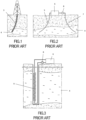
- a drilling auger is schematized in Figure 1 which produces vertical or sub-vertical wells, as shown in the Figure, in the case of slim holes.
- the drilling activity creates a well 3 which reaches an aquifer 4.
- Figure 2 typically at least two wells are drilled, i.e. a production well 5 within which the geothermal fluid extracted from the aquifer 4 flows, to a surface user 6 (for example, a power plant with organic Rankine cycle).
- the geothermal fluid after having supplied heat to the plant, is then fed to a re-injection well 7 reaching the aquifer 4 in a position relatively remote from the production well, in order to avoid feeding the user 6 with the spent, i.e. colder, fluid.
- One or more pumps can be installed along the path of the geothermal fluid, in order to keep it pressurized at the right level.
- re-injection pump 8 can be installed along the path of the geothermal fluid, in order to keep it pressurized at the right level.
- FIG. 3 shows a very simplified diagram of a bottom-well heat exchanger 9.
- the bottom-well heat exchanger has numerous advantages compared to the usual geothermal fluid transfer pattern on the surface, through a first well (the production well), used at the surface level (for example for producing electricity in a power plant), then by reintroducing (partially or entirely) the geothermal fluid through a second well (the re-injection well).
- a first well the production well
- the surface level for example for producing electricity in a power plant
- the bottom-well heat exchanger is not commonly used, as it also has several disadvantages. In particular:
- a purpose of the present invention is therefore to provide a heat exchange circuit for a geothermal plant which allows to obtain the aforementioned advantages typical of heat exchange at the bottom of a well, that is, without the need to move the geothermal fluid towards the surface.
- the invention must allow an easy and fast transfer of the equipment which is present inside the well, towards the surface, for the maintenance or replacement of components.
- a heat exchange circuit for a geothermal plant which includes a well dug into the rock for reaching an aquifer and arranged in a substantially closed ring, except for an interruption on the surface. Inside the well a casing is inserted, that includes at least one first extended perforated section along a first portion of the well and at least a second perforated section extended along a second portion of the well.
- the perforated casing sections allow an inlet and an outlet of a geothermal fluid flow contained in the aquifer.
- An internal duct is positioned inside the casing in which a heat transfer fluid flows, so that at least one bottom-well heat exchange section is formed, within which the geothermal fluid transfers heat to the heat transfer fluid.
- the heat exchange circuit and in particular the internal duct is connected to at least one user for the use of thermal energy or for the generation of electrical energy (or a combination thereof), who is located on the surface.
- This allows the heat transfer fluid, which has acquired heat energy from the geothermal source, either to give heat to a plant for the generation of electrical energy, for example by operating with a Rankine cycle or an organic Rankine cycle or a gas, or to transfer heat to a thermal user.
- interception means which seal the inner duct when it is detached from the surface users
- translation means configured to move the inner duct making it translate in any of its points, so that the portion used for the downhole heat exchange may rise to the surface and so allowing its simple and quick maintenance.
- the advantage of the present invention resides in the fact that it is not necessary to disassemble the pieces of the inner duct as the portion used for the heat exchange goes up towards the surface. Only in some special cases, as will be seen below, it may be necessary to carry out a disassembly of the adjacent and preceding duct portion (according to the direction of movement), such portion being used for heat exchange in two or more lengths of the order of 500 m.
- the duct portions being adjacent and preceding the portion used as the heat exchange and being connected to it are moved until reaching the surface through one end of the casing and they can be subsequently reintroduced in the casing itself and transferred to its inside through the opposite end of the casing itself.
- the heat exchange circuit for geothermal plants according to the present invention shows the characteristics of the independent claim 1 of the plant.
- the invention relates to a heat exchange circuit for a geothermal plant.
- HDD Horizontal Directional Drilling
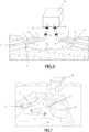
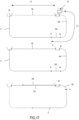
- the heat exchange circuit comprises a well 10 which is schematically shown in Figure 4 .
- the well 10 is perforated preferably starting from a large trench 15 with an inclined side 17.
- a suitable equipment 16 By means of a suitable equipment 16, the excavation of the well starts from this side, and proceeds deeper and deeper until it reaches the aquifer 4. It is necessary to reach a first portion A of the aquifer 4 which is characterized by a high permeability, so that it is suitable for receiving a flow, that is, a less hot flow, of the exhausted geothermal fluid flow.
- the perforation proceeds in a direction such as to reach a second portion B of the aquifer characterized by high temperature and a large potential reserve of geothermal fluid.
- the distance between the first portion A and the second portion B defines the heat exchange section 12 of the circuit and will preferably range between 200 meters and 2000 meters, for example with a distance of the order of magnitude of 1000 meters, so as to delay for as long as possible the mixing of the hot geothermal fluid with the exhausted geothermal fluid.
- the perforation proceeds further up to a progressively lower depth, until it reaches a point in the surface trench 15.
- the direction of perforation must be such that the starting point of the perforation C and the outlet point D are substantially aligned and the their distance on the surface is sufficient to compensate, by remaining within the limits of the mechanical resistance of the pipe, any misalignments, indicatively of the order of 100 meters.
- an effective solution schematized in Figure 14 , consists in reaching a position D1 during the raising towards the surface, which is distant from the desired position D and is characterized by a depth compatible with the guide of the perforating apparatus from the surface.
- the guide of the perforating apparatus from the surface (prior art) is in fact precise and easy: if applied for a sufficient length of well it allows to obtain an effective alignment of the access ports to the wells C and D.
- the order of magnitude of the length of the section D1-D to be adopted is a function of the diameter of the "casing" and of the guiding precision of the deep fraction of the well.
- a distance of 150 meters from the outlet point aligned with the inlet point is sufficient to give an efficient alignment. If, as a consequence of this perforation procedure of the well, an extended section at a modest depth is present, it may be advantageous to structure the plant so that the low-depth section belongs to the descent section of the heat transfer fluid, rather than the raising section, so as to minimize heat losses towards adjacent rocks.
- the next step is boring the well according to known techniques, in order to obtain the desired diameter and surface finish of the well.
- the next step is the introduction into the well of a housing 11 or casing, having a slightly smaller diameter than the well ends C and D, substantially corresponding with the same access ports to the well.
- references C and D will be used indifferently in order to identify the ends of the well 10 (i.e. the starting point and the outlet point of the perforation of the well) or of the casing 11.
- the casing 11 is characterized by at least a first perforated section extended along the first portion A and at least a second perforated section extended along the second portion B. Once realized, the casing 11 will be blocked inside the well according to known techniques, for example by cement application.
- the first portion A acts as a re-injection region of the exhausted (i.e. less hot), geothermal fluid
- the second portion B acts as a production region, where, in other words, the hot geothermal fluid can transfer heat to a heat transfer fluid.
- the curvature of the well must be small enough to obtain an acceptable level of mechanical stress inside the casing.
- the choice of the type and of the perforation area, the acceptable value of the curvature of the well, the interaction between the casing and the rocks, the best positioning of the perforated areas of the casing, are all skills which are consolidated in the geothermal or "oil & gas" field and therefore it will not be further discussed in this description.
- the result of the described operations relates to a well 10 inside which the casing 11 is mechanically positioned.
- the well 10 will be realized substantially ring-shaped, with a first portion A of re-injection and a second portion B of production.
- the positions of the two portions A and B must be such that the re-mixing of the hot fluid in portion B with the exhausted fluid in portion A is avoided for many years.
- the circulation of the geothermal fluid from the second portion B to the first portion A can take place naturally inside the casing 11, due to the pressure difference in the two positions.
- the geothermal fluid feeds the casing 11 due to the presence of the perforated sections.
- an internal duct E preferably with a circular section
- the curvature of the well must be small enough so as to obtain an acceptable stress level in the casing 11 but also in the inner duct E, which is be made of metal material, preferably in tempered steel, preferably in accordance with API, American Petroleum Institute, standards.
- the inner duct may have a non-circular section, in particular oval or elliptical, or it may be pre-deformed to allow the reduction of the minimum radius of curvature allowed for the well along its path, if this is required by the geological conditions. Again in order to contain the stresses induced in the inner duct E, i.e.
- the inner duct E may be provided with flexible elements, located at least one for each section of inner duct.
- Such flexible elements could be sections of pipes or corrugations or bi-conical couplings with a general behavior due to ball joints.
- the inner duct E supplies from the surface a suitable heat transfer fluid to the heat exchange section 12 between the second portion B and the first portion A.
- a suitable heat transfer fluid can be water and have a single-phase full path, i.e. without reaching the evaporation temperature. Its circulation inside the duct E can be assured by a circulation pump located on the surface.
- the plant may have a pressurized expansion vessel.
- suitable operating conditions may arise in causing the presence in the water circuit of one or more flash conditions, or even there may be generation of superheated or hypercritical steam along the underground path.
- the heat transfer fluid may be either a diathermal fluid, such as a mineral and synthetic diathermal oil, or CO2 or molten salts.
- the heat transfer fluid may finally be an organic working fluid, for example, cyclopentane, propane or butane, in particular "VP1" (azeotropic diphenyldiphenyl oxide).
- the heat transfer fluid receives thermal energy from the geothermal fluid by performing a heat exchange, preferably in counter-current way. Therefore the active section 12 represents to all purposes a heat exchange section 12 located at the bottom of the well, where in its most essential form, the heat exchanger at the bottom of the well consists of the casing 11 and the inner duct E, with the heat transfer fluid (exchanged heat receptor) inside the inner duct E and the geothermal fluid (transferring the exchanged heat) outside the duct E and inside the casing 11. Downstream of the active section 12, the heat transfer fluid inside the duct E is transferred to the end D at ground level.
- the inner duct can be divided into a number of pipes separated from each other, so as to constitute a tube bundle exchanger or in any case to assume a structure suitable for optimizing the heat exchange with the flow of the geothermal fluid.
- the favorable pressure difference of the first portion A with respect to the second portion B can be established by adopting a lower depth for the portion B with respect to the portion A, so as to obtain a radiator effect, due to the increase in density of the geothermal fluid during its progressive cooling in contact with the inner duct.
- the heat exchange section 12 can include a circulation pump P for pushing the geothermal fluid.
- the pump can be powered electrically, by means of a cable, from the surface.
- a turbine T can be provided for operating the circulation pump P through a shaft S.
- the turbine T is positioned along the circuit of the heat transfer fluid and is driven by the latter.
- a suitable sealing on the shaft avoids transfers of heat transfer fluid to the geothermal fluid.
- the heat transfer fluid can be water, demineralized water suitable for high temperature operation, CO2, diathermal oil, suitable hydrocarbons, molten salt.
- the heat transfer fluid can either remain in the liquid phase, or in any case it has no phase changes (for example a fluid in supercritical conditions), or alternatively it can evaporate during its path in the underground duct.
- pumps can be dedicated to the transfer of geothermal fluid, with arrangement in series or in parallel on the geothermal fluid path.
- Each pump can be driven by a turbine, with an arrangement preferably in series on the path of the fluid transfer path, supplied by the inner duct.
- the end D of the duct E is connected with the user Q.
- Such user may typically be a plant for the production of electric energy, preferably by means of an ORC cycle (Organic Rankine Cycle).
- ORC cycle Organic Rankine Cycle
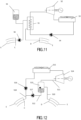
- FIG 11 a possible simplified diagram is shown in Figure 11 .
- the heat transfer fluid from the underground is supply from the exit D to a system of heat exchangers S1 between the heat transfer fluid and the organic working fluid.
- the organic working fluid in the vapor phase expands in a turbine S2 providing useful work, passes through a condenser S3 (with a cold source with air or other fluid) and returns to the liquid phase.
- a supply pump S4 brings the organic working fluid back again to the entry of the heat exchanger system S1.
- a circulation pump S6 sends the heat transfer fluid, which has transferred its heat to the organic working fluid, to the end C of the well.
- the circuit can be characterized by the presence of an expansion vessel S5 of the content of the internal duct E and of the exchanger S1 and of related connections, in the presence of significant temperature variations.
- the expansion vessel therefore represents a plenum chamber for pressurizing the circuit corresponding to the internal duct E, according to the prior art.
- a Rankine cycle with an organic fluid it is possible to use a Rankine cycle with an inorganic fluid, in particular a water vapor cycle.
- liquid water or in any case a two-phase fluid with a low vapor content
- a cycle is carried out on the surface with one or more flashes, which supply the known steam turbines.
- the entire steam system is much less expensive and more reliable than the usual plant with geothermal fluid steam.
- FIG. 12 The corresponding simplified plant diagrams are shown in Figure 12 (plant with a single "flash”) and in Figure 13 (plant with triple “flash” ).
- the heat transfer fluid coming from the duct E arrives, through a supply duct S10, from the internal duct E of the well 10 to a flash container S13.
- the live steam produced, through the pipe S11 is expanded in the steam turbine S14 and subsequently returns to the liquid state in the condenser S15.
- An extraction pump S16 from the condenser pushes this liquid back toward the entry point C of the duct E.
- the description is simplified and the actual diagram may include other pumps, such as for example a pump separate from the pumps S16 and S17, which supplies the internal duct downstream of the confluence of the flow from the flash container and the condenser.
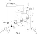
- the triple flash plant is schematized in Figure 13 .
- the operating principle is the same as in the previous plant, with the only difference that the steam turbine S22 is a multi-admission turbine, being able to receive and expand the steam coming from the three flash containers S19, S20, S21 (containers crossed in series by the portions of residual liquid by means of corresponding ducts S24, S26, S28). The steam portions will reach the turbine through corresponding ducts S23, S25, S27.
- connection between duct E and user Q is made through a pipe system, which includes the thermal expansion compensators L and M or any other means to compensate for the thermal expansion in the long underground duct, avoiding an overstressing of the material of the internal duct E.
- the return pipe towards the duct and downstream the user Q allows for the thermal expansion, by predicting the presence of additional compensators N and P.
- the users on the surface may be more than one and be powered by corresponding ducts.
- the latter may be separated from each other, or have a supply duct in common with the internal duct, or again can have in common a manifold located at the exit of the same internal duct from the well.
- systems can also be made in which different wells according to the invention are present, connected with the user in series or in parallel with each other, or with combinations of series and parallel connections.
- the pump (s) present on the surface must provide the pressure increase necessary to supply the pump drive turbine with the necessary power.
- the modulation of the flow rate and pressure of the pump can be integrated with the actuation of variable valves or nozzles, with preferably hydraulic controls from the surface, supplied by a separate duct.
- the pump itself In the presence of a well-bottom circulation pump, the pump itself must be equipped with a non-return valve, schematically indicated with V1 in Fig. 5 , preferably a petal pump, to prevent the pumped geothermal fluid from flowing back to the entry of the pump itself.
- a further way of using the invention is to use it as an electrical energy storage system with the aim of generating power when necessary, and vice versa for storing heat in the aquifer when electrical energy is not required.
- the user on the surface consists of two machines or of a reversible machine, capable of performing both the function of producing electric power and the function of a heat pump.
- the machine receives a high temperature fluid from the deep aquifer and transfers heat to a cold source (air or water).
- a receiver of excess electricity the machine transfers thermal power from the surface cold source (air or water) to the deep aquifer, raising its temperature due to the heat pump function at the expense of consuming electricity.
- this scheme can also be achieved by using two wells according to the invention, in separate aquifers which have very different temperatures. There is therefore a "hot” aquifer, presumably in the deep and a “cold” aquifer of modest depth, with an alternating flow, from hot to cold and from cold to hot, depending on the function in progress.
- the user Q is deactivated and the heat transfer fluid is no longer supplied to the internal duct E.
- the connections the end of the internal duct R and Z (for example, double cone connections) are disassembled and both ends are connected to two connectors and to any plugs.
- the two ends of the internal duct E may be connected by a pipe section E', in order to achieve a closed circuit, so by keeping in mind, as already, that the starting point of perforation C and the exit point D are substantially aligned and their distance from the surface be sufficient to compensate, by remaining within the limits of the mechanical strength of the pipe, possible misalignments, indicatively of the order of 100 meters.
- the subsequent phase is the progressive operation of the mechanisms of traction X and Y, which guide the internal duct E towards the left end C of the well, until the connector R disappears into the well.
- the movement of the duct E (counterclockwise in the illustrated case) continues still up to when the first portion 50 of the heat exchange section 12, including the section of the heat exchanger and the pump and the turbine, reach the surface and can be adequately maintained.
- a sequence of displacement of the internal duct E is shown in Fig. 8 :
- FIG. 9 A solution for pulling the tube, according to another aspect of the invention, is shown in Figure 9 , with reference to the traction mechanism X of the right side.
- the opposite traction mechanism Y is specular to the traction mechanism X.
- the reference D indicates the surface of the casing 11. Sequentially with respect to this end of the casing 11 the following elements are bolted (or in any way connected in any suitable manner):
- the elements X1 to X 4 constitute the first fixed section of the traction mechanism.
- Corresponding and equivalent elements, X6, X7 and X8 constitute a second mobile section of the traction mechanism.
- the adoption of the heat exchange circuit with a well-bottom exchanger should allow a drastic limitation of the emissions deriving from the production of electricity from geothermal sources, so reducing downtime for maintenance and reducing the time of plant implementation.
- the present invention is also applicable if a well is already present, for example a vertical well.
- Figures 15 to 18 schematically show this further embodiment of the present invention.
- the pre-existing well 100 is a vertical well on the descending side and comprises a first vertical portion 101 which, starting from the surface of the ground, reaches the level of the aquifer 4, and a second almost horizontal or sub-horizontal portion 102 which extends inside the aquifer itself.
- This may be, for example, the case of wells almost exhausted wells for the extraction of "shale gas" or gas obtained from artificially fractured clays.
- the well 10 in this embodiment, will include the existing perforation 100 and also the new construction. The difference with respect to what has been described up to now consists in that the existing well will be substantially vertical.
- the starting point CC of the pre-existing well 100 will be rather distant from the exit point D of the new perforation due to the pre-existence of the second portion 102.
- it will therefore be necessary to make a further perforation 200 or a trench, preferably sub-horizontal but however not so deep in order to obtain the ring almost closed as in the embodiment already described, albeit characterized by the abrupt transition from the substantially horizontal direction to the vertical direction of the well.
- the casing 11 is introduced into the well 10 and a second casing 77 in the sub-horizontal perforation 200.
- the same reference 77 is used for the trench.
- the inner duct E is introduced into the casing 11, inside which the heat transfer fluid will flow. It should be noted that, being the well vertical, the inner duct E can be inserted only if it is broken down into bars. Alternatively, the inner duct can be introduced from the reamed side of the well 10 (the one on the right side in Fig. 15 ) and be pulled by means of the winch AV.
- a pair of winches AV, AH can be provided as means for moving the inner duct E for the traction in the vertical direction and for a horizontal traction respectively.
- a non-translation duct 70 In order for the inner duct to be closed, in addition to the already described connections with the user Q, a non-translation duct 70 must be provided inside the casing 77 and therefore from point C to point DD and finally a fitting 75 which connects the non-translation duct 70 with the inner duct E during its translation inside the well 10.
- this portion 60 can be left on the surface (or inside the trench) or be re-introduced in a casing (in this case the casing 77) until the maintenance operations are completed.
- the length of the casing (or trench) 77 is called L1 and the length of the inner duct E, called L2, in the section from the beginning (zone A) of the active section (of the heat exchange) 12 at the exit point D, which is the first case to be analyzed, is the one in which: L 1 > L 2
- the casing 77 (or the trench) has a greater length with respect to the length of the inner duct E to be traveled, in order to bring to the surface the heat exchange section 12 for maintenance operations.
- the portion 60 of the inner duct E which precedes the heat exchange section 12 can therefore be housed within the casing 77, parallel to the non-translation portion of the inner duct 70.
- the portion 60 of the inner conduit to be housed must be divided into several sections, for example in two lengths 61, 62 illustrated in the section of Figure 18 .
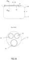
- FIG. 19 A third embodiment of the invention is shown schematically in Figure 19 .
- the heat exchange circuit illustrated therein differs from the heat exchange circuit of Figure 4 for the following characteristics:
- the geothermal fluid feeds a heat exchanger S40 of the second plant ORC2 and returns to the aquifer by means of a re-injection well 110.
- the presence of the geothermal fluid on the surface obviously taking care to avoid any form of pollution due to the content of compounds dissolved or transported by the geothermal fluid, also allows the recovery of important components for other applications, such as lithium or silica gel.
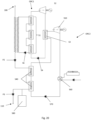
- the two plants ORC1, ORC2, mutually in cascade, are shown in Figure 20 , in one of the possible configurations.
- the plant ORC1 is the organic high temperature cycle and its hot source is represented by the heat transfer fluid which circulates in the inner duct E. This cycle is completely similar to that of the ORC cycle illustrated in Fig. 11 .
- the heat transfer fluid coming from the underground is supplied ad the exit D to a system of heat exchangers S1 between the heat transfer fluid and a first organic working fluid.
- the first organic working fluid in vapor phase expands in a turbine S2 providing useful work, through an S3 condenser, by exchanging heat with a second organic working fluid circulating in the second plant ORC2, and returning in liquid phase.
- a supply pump S4 will bring the first organic working fluid back to the inlet of the heat exchanger plant S1.
- a circulation pump S6 will transfer the heat transfer fluid, which has transferred heat to the organic working fluid, up to the end C of the well 10.
- the plant ORC2 is the low temperature organic cycle and its hot source is represented by the geothermal fluid coming from the branch 100 and supplied by the pump P2 which, as already mentioned, exchanges heat with the second organic working fluid in one or more pre-heaters S40. Then the second organic working fluid exchanges heat with the first organic working fluid in the condenser S3 of the plant ORC1.
- the condenser S3, considered as a component of ORC2 is in fact the vaporizer of this plant. According to known technique, the second organic working fluid in the vapor phase expands in a turbine S50 providing useful work, passes through a condenser S60 (with a cold source with air or other fluid) and returns to the liquid phase.
- a supply pump S70 brings the second organic working fluid back to the entry of the heat exchanger system S40.
- a re-injection pump P3 supplies the geothermal fluid, which has given heat to the organic working fluid, to the re-injection well 110.
- a device S80 may be arranged for the recovery from the geothermal fluid of compounds suitable to be used separately with respect to the geothermal fluid, for example lithium or silica gel compounds.
Landscapes
- Engineering & Computer Science (AREA)
- Life Sciences & Earth Sciences (AREA)
- Sustainable Development (AREA)
- Sustainable Energy (AREA)
- Chemical & Material Sciences (AREA)
- Combustion & Propulsion (AREA)
- Mechanical Engineering (AREA)
- General Engineering & Computer Science (AREA)
- General Life Sciences & Earth Sciences (AREA)
- Hydrology & Water Resources (AREA)
- Engine Equipment That Uses Special Cycles (AREA)
- Heat-Exchange Devices With Radiators And Conduit Assemblies (AREA)
Claims (26)
- Wärmeaustauschkreislauf für eine Geothermieanlage, bestehend aus:- einem in den Fels gegrabenen Schacht (10),- ein Gehäuse (11), das innerhalb des Schachts (10) angeordnet und mit diesem fest verbunden ist und mindestens einen ersten perforierten Abschnitt umfasst, der sich entlang eines ersten Teils (A) des Schachts (10) erstreckt, und mindestens einen zweiten perforierten Abschnitt, der sich entlang eines zweiten Teils (B) des Schachts (10) erstreckt, wobei die perforierten Abschnitte den Austritt und den Eintritt eines Stroms einer in einem Grundwasserleiter (4) enthaltenen geothermischen Flüssigkeit ermöglichen,- eine innere Leitung (E), die sich innerhalb des Gehäuses (11) befindet und in dem eine Wärmeträgerflüssigkeit strömt,- wobei der Schacht (10), das Gehäuse (11) und die innere Leitung (E) bis auf mindestens eine Oberflächenunterbrechung als im Wesentlichen geschlossener Ring angeordnet sind,- mindestens einen Wärmeaustauschabschnitt (12) am Boden des Schachts zwischen dem ersten Teil (A) und dem zweiten teil (B) des Schachts (10), in dem das geothermische Fluid Wärme an das Wärmeübertragungsfluid überträgt, und wobei dieser mindestens eine Wärmeaustauschabschnitt (12) mindestens einen ersten Teil (50) der inneren Leitung (E) umfasst,- mindestens einem Verbraucher (Q) zur Nutzung thermischer Energie oder zur Erzeugung elektrischer Energie oder einer Kombination davon, der sich an der Oberfläche befindet und mit dem die innere Leitung (E) durch einen Luftteil der Rohrleitung lösbar verbunden ist,wobei der Wärmeaustauschkreislauf dadurch gekennzeichnet ist, dass die innere Leitung (E) innerhalb des Gehäuses (11) verschiebbar ist, so dass der erste Teil (50) der inneren Leitung (E) jede beliebige Position innerhalb des Gehäuses (11) einnimmt, einschließlich einer Position am Boden des Schachts oder einer Position an der Oberfläche.
- Wärmeaustauschkreislauf nach Anspruch 1, wobei ein zweiter allgemeiner Teil (60) der inneren Leitung (E) eine beliebige Position innerhalb des Gehäuses (11) einnimmt.
- Wärmeaustauschkreislauf nach Anspruch 2, der außerdem ein zweites Gehäuse oder einen Graben (77) umfasst, der eine nicht verschiebbare Leitung (70) enthält, die mechanisch und hydraulisch mit der inneren Leitung (E) verbunden ist, wobei der zweite Teil (60) der inneren Leitung (E) aufgrund der Verschiebbarkeit der inneren Leitung (E) in das zweite Gehäuse oder in den Graben (77) hineinragt.
- Wärmeaustauschkreislauf nach Anspruch 3, wobei der zweite allgemeine Teil (60) zwei oder mehr Stücke (61, 62) umfasst.
- Wärmeaustauschkreislauf nach einem der vorhergehenden Ansprüche, wobei im Wärmeaustauschabschnitt (12) am Boden des Schachts die innere Leitung (E) in eine Anzahl von voneinander getrennten Rohren unterteilt ist, um einen Rohrbündelwärmetauscher zu bilden, der den Wärmeaustausch der Wärmeübertragungsflüssigkeit mit der geothermischen Flüssigkeit optimiert.
- Wärmeaustauschkreislauf nach einem der vorhergehenden Ansprüche, wobei sich der zweite Teil (B) des Schachts (10) in einer geringeren Tiefe befindet als der erste Teil (A), um eine natürliche Zirkulation der geothermischen Flüssigkeit während ihrer fortschreitenden Abkühlung in Kontakt mit der inneren Leitung (E) zu erreichen.
- Wärmeaustauschkreislauf nach einem der Ansprüche 1 bis 5, wobei sich im Wärmeaustauschabschnitt (12) am Boden des Schachts eine Umwälzpumpe (P) für die geothermische Flüssigkeit befindet.
- Wärmeaustauschkreislauf nach Anspruch 7, wobei die Umwälzpumpe (P) eine elektrische Pumpe ist, die über ein Kabel von der Oberfläche gespeist wird.
- Wärmeaustauschkreislauf nach Anspruch 7, wobei die Umwälzpumpe (P) von einer Turbine (T) angetrieben wird, die entlang des Wärmeübertragungsflüssigkeitskreislaufs angeordnet ist und von diesem angetrieben wird.
- Wärmeaustauschkreislauf nach einem der vorhergehenden Ansprüche, wobei der Abstand zwischen dem ersten Teil (A) des Schachts (10) und dem zweiten Teil (B) des Schachts (10) zwischen 200 Metern und 2000 Metern liegt.
- Wärmeaustauschkreislauf nach einem der vorhergehenden Ansprüche, wobei die Verbindung der inneren Leitung (E) mit dem Verbraucher (Q) über mindestens zwei Leitungen erfolgt, die mit Ausdehnungskompensatoren (L, M, N, P) ausgestattet sind, um eine Überbeanspruchung des Materials der inneren Leitung (E) zu vermeiden.
- Wärmeaustauschkreislauf nach einem der vorhergehenden Ansprüche, wobei es sich bei der Wärmeübertragungsflüssigkeit um Wasser in einphasiger oder zweiphasiger Form handelt oder wobei entlang des unterirdischen Pfads überhitzter oder hyperkritischer Dampf erzeugt wird.
- Wärmeaustauschkreislauf nach einem der Ansprüche 1 bis 11, wobei die Wärmeübertragungsflüssigkeit eine diathermische Flüssigkeit ist, wie etwa mineralisches und synthetisches diathermisches Öl, CO2 oder geschmolzene Salze.
- Wärmeaustauschkreislauf nach einem der Ansprüche 1 bis 11, wobei das Wärmeträgerfluid ein organisches Arbeitsfluid, insbesondere ein Azeotrop aus Diphenyldiphenyloxid, Cyclopentan, Propan oder Butan, ist.
- Wärmeaustauschkreislauf nach einem der vorhergehenden Ansprüche, wobei die innere Leitung (E) einen kreisförmigen Querschnitt aufweist.
- Wärmeaustauschkreislauf nach einem der Ansprüche 1 bis 14, wobei die innere Leitung (E) einen lokal ovalen oder elliptischen Querschnitt aufweist.
- Wärmetauschkreislauf nach einem der vorhergehenden Ansprüche, wobei die innere Leitung (E) vorverformt ist.
- Wärmeaustauschkreislauf nach einem der vorhergehenden Ansprüche, wobei die innere Leitung (E) mit flexiblen Elementen versehen ist.
- Wärmeaustauschkreislauf nach Anspruch 18, wobei die flexiblen Elemente Wellrohrabschnitte sind oder mit Balgwellungen versehen sind, oder Kugelgelenke, die zwei Rohrabschnitte miteinander verbinden.
- Wärmeaustauschkreislauf nach einem der vorhergehenden Ansprüche, wobei der Abstand zwischen einem Startpunkt (C) des Schachts (10) und einem Austrittspunkt (D) des Schachts (10) nicht mehr als 100 Meter beträgt.
- Wärmeaustauschkreislauf nach Anspruch 20, wobei eine Position (D1) des Schachts (10), die sich vom Austrittspunkt (D) des Schachts (10) unterscheidet, einen Abstand von mehr als 150 Metern vom Austrittspunkt (D) des Schachts (10) aufweist.
- Wärmeaustauschkreislauf nach einem der vorhergehenden Ansprüche, weiterhin umfassend Abfangmittel zum Abdichten der inneren Leitung (E), wenn diese vom Benutzer abgelöst wird, und Translationsmittel, die zum Bewegen der inneren Leitung (E) konfiguriert sind.
- Wärmetauschkreislauf nach einem der vorhergehenden Ansprüche, dadurch gekennzeichnet, dass:- die Zone der Fensteroberfläche des ersten perforierten Anschnitts, die sich entlang des ersten Teils (A) des Schachts (10) erstreckt, kleiner als die Zone der Fensteroberfläche des zweiten perforierten Abschnitts ist, der sich entlang des zweiten Teils (B) des Schachts (10) erstreckt, so dass ein Prozentsatz der geothermischen Flüssigkeit in dem Gehäuse (11) verbleibt;- das Gehäuse (11) einen Abzweig (100) aufweist, der das Gehäuse (11) mit dem mindestens einen Verbraucher (Q, ORC1) und/oder mit mindestens einem zweiten Verbraucher (ORC2) verbindet.
- Wärmeaustauschkreislauf nach dem vorhergehenden Anspruch, dadurch gekennzeichnet, dass die Zone der Fensteroberfläche des ersten perforierten Abschnitts, der sich entlang des ersten Teils (A) des Schachts (10) erstreckt, im Wesentlichen gleich Null ist, so dass der gesamte Fluss der geothermischen Flüssigkeit in dem Gehäuse (11) enthalten bleibt und an die Oberfläche übertragen wird.
- Wärmeaustauschkreislauf nach Anspruch 23 oder 24, dadurch gekennzeichnet, dass der zweite Verbraucher (ORC2) eine Vorrichtung (S80) zur Rückgewinnung von Lithium-Verbindungen oder Silicagel aus dem geothermischen Fluid umfasst.
- Verfahren zur Wartung eines Wärmetauschkreislaufs nach einem der vorhergehenden Ansprüche, umfassend die folgenden Schritte:a) Abtrennen des oberirdischen Teils der Rohrleitung,b) Verschließen der Enden (R) und (Z) der inneren Leitung (E),c) Verschieben der inneren Leitung (E),so dass der erste Teil (50) der inneren Leitung (E), der im Wärmeaustauschabschnitt (12) enthalten ist, zu aufeinanderfolgenden Zeitpunkten Positionen einnimmt, die fortschreitend näher an die Oberfläche sind, bis sie ein Oberflächenende des Gehäuses (11) passiert, und daher aus dem Gehäuse selbst herausschiebbar ist, undso dass ein allgemeiner zweiter Teil (60) der inneren Leitung (E) verschoben wird, bis er durch ein Ende des Gehäuses (11) die Oberfläche erreicht, und anschließend wieder in das Gehäuse (11) eingeführt und darin durch das entgegengesetzte Ende des Gehäuses verschoben wird oder an der Oberfläche verbleibt, bis die Wartungsarbeiten abgeschlossen sind,d) Durchführen von Wartungsarbeiten an den Komponenten, die diese benötigen,e) Neupositionieren der inneren Leitung (E) durch Bewegen in die gleiche oder in die entgegengesetzte Richtung wie in Punkt c) durchgeführt, so dass der erste Teil (50) der inneren Leitung (E) durch das entgegengesetzte oder das gleiche Ende des Gehäuses selbst, wie in Punkt c) erwähnt, in weitere Positionen innerhalb des Gehäuses (11) verschoben wird, bis der erste Teil (50) in seiner anfänglichen Betriebsposition untergebracht ist,f) Wiederanschließen des Luftrohrleitungsabschnitts.
Applications Claiming Priority (2)
| Application Number | Priority Date | Filing Date | Title |
|---|---|---|---|
| IT102019000006817A IT201900006817A1 (it) | 2019-05-14 | 2019-05-14 | Circuito di scambio termico per impianto geotermico |
| PCT/IB2020/053343 WO2020229901A1 (en) | 2019-05-14 | 2020-04-08 | Heat exchange circuit for a geothermal plant |
Publications (3)
| Publication Number | Publication Date |
|---|---|
| EP3969822A1 EP3969822A1 (de) | 2022-03-23 |
| EP3969822B1 true EP3969822B1 (de) | 2024-06-12 |
| EP3969822C0 EP3969822C0 (de) | 2024-06-12 |
Family
ID=67660737
Family Applications (1)
| Application Number | Title | Priority Date | Filing Date |
|---|---|---|---|
| EP20721738.1A Active EP3969822B1 (de) | 2019-05-14 | 2020-04-08 | Wärmeaustauschkreislauf für eine geothermische anlage |
Country Status (4)
| Country | Link |
|---|---|
| US (1) | US11802716B2 (de) |
| EP (1) | EP3969822B1 (de) |
| IT (1) | IT201900006817A1 (de) |
| WO (1) | WO2020229901A1 (de) |
Cited By (1)
| Publication number | Priority date | Publication date | Assignee | Title |
|---|---|---|---|---|
| WO2025265145A1 (en) * | 2024-06-21 | 2025-12-26 | Greenfire Energy Inc. | Heat extraction method for liquid dominated geothermal reservoirs |
Families Citing this family (15)
| Publication number | Priority date | Publication date | Assignee | Title |
|---|---|---|---|---|
| US11421663B1 (en) | 2021-04-02 | 2022-08-23 | Ice Thermal Harvesting, Llc | Systems and methods for generation of electrical power in an organic Rankine cycle operation |
| US11493029B2 (en) | 2021-04-02 | 2022-11-08 | Ice Thermal Harvesting, Llc | Systems and methods for generation of electrical power at a drilling rig |
| US11644015B2 (en) | 2021-04-02 | 2023-05-09 | Ice Thermal Harvesting, Llc | Systems and methods for generation of electrical power at a drilling rig |
| US11293414B1 (en) | 2021-04-02 | 2022-04-05 | Ice Thermal Harvesting, Llc | Systems and methods for generation of electrical power in an organic rankine cycle operation |
| US11480074B1 (en) | 2021-04-02 | 2022-10-25 | Ice Thermal Harvesting, Llc | Systems and methods utilizing gas temperature as a power source |
| US12312981B2 (en) | 2021-04-02 | 2025-05-27 | Ice Thermal Harvesting, Llc | Systems and methods utilizing gas temperature as a power source |
| US11359576B1 (en) | 2021-04-02 | 2022-06-14 | Ice Thermal Harvesting, Llc | Systems and methods utilizing gas temperature as a power source |
| US11592009B2 (en) | 2021-04-02 | 2023-02-28 | Ice Thermal Harvesting, Llc | Systems and methods for generation of electrical power at a drilling rig |
| US11486370B2 (en) | 2021-04-02 | 2022-11-01 | Ice Thermal Harvesting, Llc | Modular mobile heat generation unit for generation of geothermal power in organic Rankine cycle operations |
| US11255315B1 (en) | 2021-04-02 | 2022-02-22 | Ice Thermal Harvesting, Llc | Controller for controlling generation of geothermal power in an organic Rankine cycle operation during hydrocarbon production |
| CA3219367A1 (en) * | 2021-05-07 | 2022-11-10 | Rabindranath Sharma | Thermal energy storage and retrieval system |
| IT202100017711A1 (it) * | 2021-07-06 | 2023-01-06 | Geolog S R L | Metodo per installare un impianto geotermico, metodo per sfruttare energia geotermica, e impianto geotermico |
| PL442088A1 (pl) * | 2022-08-24 | 2024-02-26 | Janusz Nowakowski | Sposób wytwarzania energii elektrycznej w hybrydowej elektrowni grawitacyjno-geotermalnej, oraz układ do wytwarzania energii elektrycznej w hybrydowej elektrowni grawitacyjno-geotermalnej pracującej w obiegu zamkniętym |
| US12180861B1 (en) | 2022-12-30 | 2024-12-31 | Ice Thermal Harvesting, Llc | Systems and methods to utilize heat carriers in conversion of thermal energy |
| CN119042824B (zh) * | 2024-07-17 | 2025-09-16 | 中国矿业大学 | 一种固废胶结功能充填体布置管道提取地热方法 |
Citations (2)
| Publication number | Priority date | Publication date | Assignee | Title |
|---|---|---|---|---|
| EP2085718B1 (de) * | 2008-02-04 | 2012-04-25 | Technische Universität Hamburg-Harburg | Erdwärmeanlage |
| EP2676008B1 (de) * | 2011-02-18 | 2017-03-29 | Exergy S.p.A. | Vorrichtung und verfahren zur energieerzeugung durch einen organischen rankine-kreislauf |
Family Cites Families (40)
| Publication number | Priority date | Publication date | Assignee | Title |
|---|---|---|---|---|
| US3938592A (en) * | 1970-03-23 | 1976-02-17 | Ivan Timofeevich Aladiev | Rock-exploitation method based on thermodynamic cycles utilizing in-situ energy source |
| US4019577A (en) * | 1976-02-23 | 1977-04-26 | Mobil Oil Corporation | Thermal energy production by in situ combustion of coal |
| US4059959A (en) * | 1976-11-05 | 1977-11-29 | Sperry Rand Corporation | Geothermal energy processing system with improved heat rejection |
| US4327561A (en) * | 1980-06-20 | 1982-05-04 | Mcneal G Russell | High coefficient of performance heat pump |
| SE456431B (sv) * | 1987-02-06 | 1988-10-03 | Bo Andreasson | Palningsmetod |
| US5411085A (en) * | 1993-11-01 | 1995-05-02 | Camco International Inc. | Spoolable coiled tubing completion system |
| US5515679A (en) * | 1995-01-13 | 1996-05-14 | Jerome S. Spevack | Geothermal heat mining and utilization |
| US6250371B1 (en) * | 1995-09-12 | 2001-06-26 | Enlink Geoenergy Services, Inc. | Energy transfer systems |
| US5634515A (en) * | 1995-12-28 | 1997-06-03 | Lambert; Kenneth W. | Geothermal heat-pump system and installation of same |
| US6142215A (en) * | 1998-08-14 | 2000-11-07 | Edg, Incorporated | Passive, thermocycling column heat-exchanger system |
| US6301894B1 (en) * | 2000-05-12 | 2001-10-16 | Albert H. Halff | Geothermal power generator |
| US7048037B2 (en) * | 2003-12-09 | 2006-05-23 | Mcnair Edward F | Geothermal heating and/or cooling apparatus and method of using same |
| WO2006029112A1 (en) * | 2004-09-08 | 2006-03-16 | Sovani Meksvanh | Solar augmented geothermal energy |
| ITTO20060021A1 (it) | 2006-01-13 | 2007-07-14 | Soilmec Spa | Sistema di perforazione del terreno per realizzare la circolazione di fluido in un impianto per lo sfruttamento dell'energia geotermica. |
| US20070245729A1 (en) * | 2006-04-21 | 2007-10-25 | Mickleson D Lynn | Directional geothermal energy system and method |
| EP1978314A1 (de) * | 2007-04-03 | 2008-10-08 | Iride S.r.l. | Erdwärmesonde |
| EP2198208A1 (de) * | 2007-09-28 | 2010-06-23 | Geo-en Energy Technologies Gmbh | Grundwasserbrunnen |
| US20090211757A1 (en) * | 2008-02-21 | 2009-08-27 | William Riley | Utilization of geothermal energy |
| JP2012524235A (ja) * | 2009-04-20 | 2012-10-11 | アンゾイック・エナジー・インコーポレーテッド | 地中連続ループ熱交換器と、その製造方法ならびに加熱、冷却またはエネルギー貯蔵の方法 |
| NL1037890C2 (nl) * | 2010-04-06 | 2011-10-13 | Demar Heiwerken B V | Werkwijze voor het in een bodem inbrengen van een langwerpig element |
| US20110041500A1 (en) * | 2009-08-19 | 2011-02-24 | William Riley | Supplemental heating for geothermal energy system |
| US20110192566A1 (en) * | 2010-02-08 | 2011-08-11 | Dale Marshall | Thermal storage system for use in connection with a thermal conductive wall structure |
| IT1402940B1 (it) * | 2010-11-18 | 2013-09-27 | Bellinello | Sonda geotermica a circuito chiuso |
| US20120174581A1 (en) * | 2011-01-06 | 2012-07-12 | Vaughan Susanne F | Closed-Loop Systems and Methods for Geothermal Electricity Generation |
| US20130042997A1 (en) * | 2011-08-15 | 2013-02-21 | Tai-Her Yang | Open-loopnatural thermal energy releasing system wtih partialreflux |
| SK6432Y1 (sk) * | 2012-06-05 | 2013-05-03 | Michal Masaryk | Cooling method of photovoltaic panel and system for carrying out this method |
| JP6138475B2 (ja) * | 2012-11-20 | 2017-05-31 | ゼネラルヒートポンプ工業株式会社 | 地中熱交換器 |
| EP3114349B1 (de) * | 2014-03-07 | 2019-11-06 | Greenfire Energy Inc. | Verfahren und system zur herstellung von geothermischer energie |
| US20150285226A1 (en) * | 2014-04-04 | 2015-10-08 | Richard James Archambeau | Geothermal Energy Production Using a Closed-Loop Heat Exchange System |
| CA2999878C (en) * | 2015-09-24 | 2023-02-07 | Geothermic Solution, Llc | Geothermal heat harvesters |
| JP6735839B2 (ja) * | 2016-02-25 | 2020-08-05 | グリーンファイヤー エナジー インコーポレイテッド | 閉ループシステムを用いる発電のための高温低透過性地層からの地中熱回収 |
| US10927604B2 (en) * | 2016-04-01 | 2021-02-23 | Board of Regents of the University of the Nevada System of Higher Education, on behalf of the University Nevada, Reno | Systems and methods for enhancing energy extraction from geothermal wells |
| CA2998782A1 (en) * | 2017-04-08 | 2018-10-08 | Alberta Geothermal Corporation | Method and apparatus for recycling wells for energy production in a geothermal environment |
| HU231047B1 (en) * | 2017-06-12 | 2020-01-28 | Civis Therm Kft | Geothermal insulating system and method |
| JP7475273B2 (ja) * | 2017-09-28 | 2024-04-26 | エイチエムエフエスエフ・アイピー・ホールディングス・エルエルシー | 地球内部からの熱を使用して発電するシステムおよび方法 |
| US10598160B2 (en) * | 2017-09-28 | 2020-03-24 | Hmfsf Ip Holdings, Llc | Systems and methods of generating electricity using heat from within the earth |
| CA3013374A1 (en) * | 2017-10-31 | 2019-04-30 | Eavor Technologies Inc. | Method and apparatus for repurposing well sites for geothermal energy production |
| CN207849806U (zh) * | 2017-11-07 | 2018-09-11 | 西安智水环境科技有限公司 | 一种地热加热气流推升抗逆温层消霾系统 |
| US11274856B2 (en) * | 2017-11-16 | 2022-03-15 | Ari Peter Berman | Method of deploying a heat exchanger pipe |
| CN208059015U (zh) * | 2018-03-02 | 2018-11-06 | 兰州交通大学 | 一种利用地热能的集中供暖设备 |
-
2019
- 2019-05-14 IT IT102019000006817A patent/IT201900006817A1/it unknown
-
2020
- 2020-04-08 EP EP20721738.1A patent/EP3969822B1/de active Active
- 2020-04-08 WO PCT/IB2020/053343 patent/WO2020229901A1/en not_active Ceased
- 2020-04-08 US US17/603,232 patent/US11802716B2/en active Active
Patent Citations (2)
| Publication number | Priority date | Publication date | Assignee | Title |
|---|---|---|---|---|
| EP2085718B1 (de) * | 2008-02-04 | 2012-04-25 | Technische Universität Hamburg-Harburg | Erdwärmeanlage |
| EP2676008B1 (de) * | 2011-02-18 | 2017-03-29 | Exergy S.p.A. | Vorrichtung und verfahren zur energieerzeugung durch einen organischen rankine-kreislauf |
Cited By (1)
| Publication number | Priority date | Publication date | Assignee | Title |
|---|---|---|---|---|
| WO2025265145A1 (en) * | 2024-06-21 | 2025-12-26 | Greenfire Energy Inc. | Heat extraction method for liquid dominated geothermal reservoirs |
Also Published As
| Publication number | Publication date |
|---|---|
| WO2020229901A1 (en) | 2020-11-19 |
| US20220186984A1 (en) | 2022-06-16 |
| EP3969822C0 (de) | 2024-06-12 |
| IT201900006817A1 (it) | 2020-11-14 |
| US11802716B2 (en) | 2023-10-31 |
| EP3969822A1 (de) | 2022-03-23 |
Similar Documents
| Publication | Publication Date | Title |
|---|---|---|
| EP3969822B1 (de) | Wärmeaustauschkreislauf für eine geothermische anlage | |
| AU2023204241B2 (en) | Geothermal heat harvesters | |
| JP7516306B2 (ja) | 地熱を発生させるプロセスおよび方法 | |
| US4776169A (en) | Geothermal energy recovery apparatus | |
| US11852383B2 (en) | Geothermal power from superhot geothermal fluid and magma reservoirs | |
| US20100031653A1 (en) | Method and device for the utilization of supercritical subsurface steam in combination with supercritical thermal and hydraulic power stations | |
| US20220018577A1 (en) | Groundwater enhanced geothermal heat pump | |
| US12055131B2 (en) | Geothermal power from superhot geothermal fluid and magma reservoirs | |
| US12326278B2 (en) | Geothermal power from superhot geothermal fluid and magma reservoirs | |
| CN201705207U (zh) | 高温高压空气喷射破岩钻井装置 | |
| CN114719455A (zh) | 一种基于不同相态co2的定向层位式地热强化开采方法 | |
| CN119412299A (zh) | 基于废弃矿井再利用的相变发电系统 | |
| AU2021344816A1 (en) | Geothermal heat exchange apparatus | |
| CN113374659A (zh) | 一种基于二氧化碳闭式循环的干热岩发电系统 | |
| RU2846988C2 (ru) | Насосное устройство и способ закачки сверхгорячих геотермальных жидкостей из подземных резервуаров | |
| JP2025507859A (ja) | 超高温地熱流体及びマグマ貯留層からの地熱発電 |
Legal Events
| Date | Code | Title | Description |
|---|---|---|---|
| STAA | Information on the status of an ep patent application or granted ep patent |
Free format text: STATUS: UNKNOWN |
|
| STAA | Information on the status of an ep patent application or granted ep patent |
Free format text: STATUS: THE INTERNATIONAL PUBLICATION HAS BEEN MADE |
|
| PUAI | Public reference made under article 153(3) epc to a published international application that has entered the european phase |
Free format text: ORIGINAL CODE: 0009012 |
|
| STAA | Information on the status of an ep patent application or granted ep patent |
Free format text: STATUS: REQUEST FOR EXAMINATION WAS MADE |
|
| 17P | Request for examination filed |
Effective date: 20211110 |
|
| AK | Designated contracting states |
Kind code of ref document: A1 Designated state(s): AL AT BE BG CH CY CZ DE DK EE ES FI FR GB GR HR HU IE IS IT LI LT LU LV MC MK MT NL NO PL PT RO RS SE SI SK SM TR |
|
| DAV | Request for validation of the european patent (deleted) | ||
| DAX | Request for extension of the european patent (deleted) | ||
| REG | Reference to a national code |
Ref country code: DE Free format text: PREVIOUS MAIN CLASS: F24T0010150000 Ref country code: DE Ref legal event code: R079 Ref document number: 602020032295 Country of ref document: DE Free format text: PREVIOUS MAIN CLASS: F24T0010150000 Ipc: F24T0010300000 |
|
| RIC1 | Information provided on ipc code assigned before grant |
Ipc: F24T 10/00 20180101ALI20231129BHEP Ipc: F24T 10/20 20180101ALI20231129BHEP Ipc: F24T 10/15 20180101ALI20231129BHEP Ipc: F24T 10/30 20180101AFI20231129BHEP |
|
| GRAP | Despatch of communication of intention to grant a patent |
Free format text: ORIGINAL CODE: EPIDOSNIGR1 |
|
| STAA | Information on the status of an ep patent application or granted ep patent |
Free format text: STATUS: GRANT OF PATENT IS INTENDED |
|
| INTG | Intention to grant announced |
Effective date: 20240108 |
|
| GRAS | Grant fee paid |
Free format text: ORIGINAL CODE: EPIDOSNIGR3 |
|
| GRAA | (expected) grant |
Free format text: ORIGINAL CODE: 0009210 |
|
| STAA | Information on the status of an ep patent application or granted ep patent |
Free format text: STATUS: THE PATENT HAS BEEN GRANTED |
|
| AK | Designated contracting states |
Kind code of ref document: B1 Designated state(s): AL AT BE BG CH CY CZ DE DK EE ES FI FR GB GR HR HU IE IS IT LI LT LU LV MC MK MT NL NO PL PT RO RS SE SI SK SM TR |
|
| REG | Reference to a national code |
Ref country code: GB Ref legal event code: FG4D |
|
| REG | Reference to a national code |
Ref country code: CH Ref legal event code: EP |
|
| REG | Reference to a national code |
Ref country code: DE Ref legal event code: R096 Ref document number: 602020032295 Country of ref document: DE |
|
| REG | Reference to a national code |
Ref country code: IE Ref legal event code: FG4D |
|
| U01 | Request for unitary effect filed |
Effective date: 20240628 |
|
| U07 | Unitary effect registered |
Designated state(s): AT BE BG DE DK EE FI FR IT LT LU LV MT NL PT RO SE SI Effective date: 20240902 |
|
| PG25 | Lapsed in a contracting state [announced via postgrant information from national office to epo] |
Ref country code: HR Free format text: LAPSE BECAUSE OF FAILURE TO SUBMIT A TRANSLATION OF THE DESCRIPTION OR TO PAY THE FEE WITHIN THE PRESCRIBED TIME-LIMIT Effective date: 20240612 |
|
| PG25 | Lapsed in a contracting state [announced via postgrant information from national office to epo] |
Ref country code: GR Free format text: LAPSE BECAUSE OF FAILURE TO SUBMIT A TRANSLATION OF THE DESCRIPTION OR TO PAY THE FEE WITHIN THE PRESCRIBED TIME-LIMIT Effective date: 20240913 |
|
| PG25 | Lapsed in a contracting state [announced via postgrant information from national office to epo] |
Ref country code: ES Free format text: LAPSE BECAUSE OF FAILURE TO SUBMIT A TRANSLATION OF THE DESCRIPTION OR TO PAY THE FEE WITHIN THE PRESCRIBED TIME-LIMIT Effective date: 20240612 |
|
| PG25 | Lapsed in a contracting state [announced via postgrant information from national office to epo] |
Ref country code: NO Free format text: LAPSE BECAUSE OF FAILURE TO SUBMIT A TRANSLATION OF THE DESCRIPTION OR TO PAY THE FEE WITHIN THE PRESCRIBED TIME-LIMIT Effective date: 20240912 Ref country code: HR Free format text: LAPSE BECAUSE OF FAILURE TO SUBMIT A TRANSLATION OF THE DESCRIPTION OR TO PAY THE FEE WITHIN THE PRESCRIBED TIME-LIMIT Effective date: 20240612 Ref country code: GR Free format text: LAPSE BECAUSE OF FAILURE TO SUBMIT A TRANSLATION OF THE DESCRIPTION OR TO PAY THE FEE WITHIN THE PRESCRIBED TIME-LIMIT Effective date: 20240913 Ref country code: ES Free format text: LAPSE BECAUSE OF FAILURE TO SUBMIT A TRANSLATION OF THE DESCRIPTION OR TO PAY THE FEE WITHIN THE PRESCRIBED TIME-LIMIT Effective date: 20240612 Ref country code: RS Free format text: LAPSE BECAUSE OF FAILURE TO SUBMIT A TRANSLATION OF THE DESCRIPTION OR TO PAY THE FEE WITHIN THE PRESCRIBED TIME-LIMIT Effective date: 20240912 |
|
| PG25 | Lapsed in a contracting state [announced via postgrant information from national office to epo] |
Ref country code: PL Free format text: LAPSE BECAUSE OF FAILURE TO SUBMIT A TRANSLATION OF THE DESCRIPTION OR TO PAY THE FEE WITHIN THE PRESCRIBED TIME-LIMIT Effective date: 20240612 |
|
| PG25 | Lapsed in a contracting state [announced via postgrant information from national office to epo] |
Ref country code: IS Free format text: LAPSE BECAUSE OF FAILURE TO SUBMIT A TRANSLATION OF THE DESCRIPTION OR TO PAY THE FEE WITHIN THE PRESCRIBED TIME-LIMIT Effective date: 20241012 |
|
| PG25 | Lapsed in a contracting state [announced via postgrant information from national office to epo] |
Ref country code: CZ Free format text: LAPSE BECAUSE OF FAILURE TO SUBMIT A TRANSLATION OF THE DESCRIPTION OR TO PAY THE FEE WITHIN THE PRESCRIBED TIME-LIMIT Effective date: 20240612 |
|
| PG25 | Lapsed in a contracting state [announced via postgrant information from national office to epo] |
Ref country code: SK Free format text: LAPSE BECAUSE OF FAILURE TO SUBMIT A TRANSLATION OF THE DESCRIPTION OR TO PAY THE FEE WITHIN THE PRESCRIBED TIME-LIMIT Effective date: 20240612 |
|
| PG25 | Lapsed in a contracting state [announced via postgrant information from national office to epo] |
Ref country code: SM Free format text: LAPSE BECAUSE OF FAILURE TO SUBMIT A TRANSLATION OF THE DESCRIPTION OR TO PAY THE FEE WITHIN THE PRESCRIBED TIME-LIMIT Effective date: 20240612 |
|
| PG25 | Lapsed in a contracting state [announced via postgrant information from national office to epo] |
Ref country code: SM Free format text: LAPSE BECAUSE OF FAILURE TO SUBMIT A TRANSLATION OF THE DESCRIPTION OR TO PAY THE FEE WITHIN THE PRESCRIBED TIME-LIMIT Effective date: 20240612 Ref country code: SK Free format text: LAPSE BECAUSE OF FAILURE TO SUBMIT A TRANSLATION OF THE DESCRIPTION OR TO PAY THE FEE WITHIN THE PRESCRIBED TIME-LIMIT Effective date: 20240612 Ref country code: PL Free format text: LAPSE BECAUSE OF FAILURE TO SUBMIT A TRANSLATION OF THE DESCRIPTION OR TO PAY THE FEE WITHIN THE PRESCRIBED TIME-LIMIT Effective date: 20240612 Ref country code: IS Free format text: LAPSE BECAUSE OF FAILURE TO SUBMIT A TRANSLATION OF THE DESCRIPTION OR TO PAY THE FEE WITHIN THE PRESCRIBED TIME-LIMIT Effective date: 20241012 Ref country code: CZ Free format text: LAPSE BECAUSE OF FAILURE TO SUBMIT A TRANSLATION OF THE DESCRIPTION OR TO PAY THE FEE WITHIN THE PRESCRIBED TIME-LIMIT Effective date: 20240612 |
|
| PLBE | No opposition filed within time limit |
Free format text: ORIGINAL CODE: 0009261 |
|
| STAA | Information on the status of an ep patent application or granted ep patent |
Free format text: STATUS: NO OPPOSITION FILED WITHIN TIME LIMIT |
|
| 26N | No opposition filed |
Effective date: 20250313 |
|
| U20 | Renewal fee for the european patent with unitary effect paid |
Year of fee payment: 6 Effective date: 20250422 |
|
| PGFP | Annual fee paid to national office [announced via postgrant information from national office to epo] |
Ref country code: TR Payment date: 20250402 Year of fee payment: 6 |
|
| REG | Reference to a national code |
Ref country code: CH Ref legal event code: H13 Free format text: ST27 STATUS EVENT CODE: U-0-0-H10-H13 (AS PROVIDED BY THE NATIONAL OFFICE) Effective date: 20251125 |
|
| PG25 | Lapsed in a contracting state [announced via postgrant information from national office to epo] |
Ref country code: MC Free format text: LAPSE BECAUSE OF FAILURE TO SUBMIT A TRANSLATION OF THE DESCRIPTION OR TO PAY THE FEE WITHIN THE PRESCRIBED TIME-LIMIT Effective date: 20240612 |
|
| GBPC | Gb: european patent ceased through non-payment of renewal fee |
Effective date: 20250408 |
|
| PG25 | Lapsed in a contracting state [announced via postgrant information from national office to epo] |
Ref country code: GB Free format text: LAPSE BECAUSE OF NON-PAYMENT OF DUE FEES Effective date: 20250408 |