EP3969693B1 - Verankerungsanordnung und zugehörige umzäunung - Google Patents
Verankerungsanordnung und zugehörige umzäunung Download PDFInfo
- Publication number
- EP3969693B1 EP3969693B1 EP19891688.4A EP19891688A EP3969693B1 EP 3969693 B1 EP3969693 B1 EP 3969693B1 EP 19891688 A EP19891688 A EP 19891688A EP 3969693 B1 EP3969693 B1 EP 3969693B1
- Authority
- EP
- European Patent Office
- Prior art keywords
- shank
- anchoring assembly
- jaw
- post
- assembly according
- Prior art date
- Legal status (The legal status is an assumption and is not a legal conclusion. Google has not performed a legal analysis and makes no representation as to the accuracy of the status listed.)
- Active
Links
Images





Classifications
-
- E—FIXED CONSTRUCTIONS
- E04—BUILDING
- E04H—BUILDINGS OR LIKE STRUCTURES FOR PARTICULAR PURPOSES; SWIMMING OR SPLASH BATHS OR POOLS; MASTS; FENCING; TENTS OR CANOPIES, IN GENERAL
- E04H17/00—Fencing, e.g. fences, enclosures, corrals
- E04H17/14—Fences constructed of rigid elements, e.g. with additional wire fillings or with posts
- E04H17/16—Fences constructed of rigid elements, e.g. with additional wire fillings or with posts using prefabricated panel-like elements, e.g. wired frames
- E04H17/161—Fences constructed of rigid elements, e.g. with additional wire fillings or with posts using prefabricated panel-like elements, e.g. wired frames using wire panels
-
- E—FIXED CONSTRUCTIONS
- E04—BUILDING
- E04H—BUILDINGS OR LIKE STRUCTURES FOR PARTICULAR PURPOSES; SWIMMING OR SPLASH BATHS OR POOLS; MASTS; FENCING; TENTS OR CANOPIES, IN GENERAL
- E04H17/00—Fencing, e.g. fences, enclosures, corrals
- E04H17/02—Wire fencing, e.g. made of wire mesh
- E04H17/10—Wire fencing, e.g. made of wire mesh characterised by the way of connecting wire to posts; Droppers
- E04H17/124—Wire fencing, e.g. made of wire mesh characterised by the way of connecting wire to posts; Droppers connecting by one or more clamps, clips, screws, wedges or ties
Definitions
- the present invention relates to an anchoring assembly and to an associated fencing.
- DE3937791C1 discloses such a fencing according to the prior art.
- Enclosures are therefore well known which are constituted by one or more laminar screens (be they continuous panels or reticular grilles), which are kept vertical by respective supporting posts, arranged at the sides.
- the enclosures described above are modular, and are assembled starting from kits that comprise a plurality of screens and posts (and corresponding accessories) which can be combined in various ways, in order to deploy the fencing along the perimeter of interest.
- the kit includes a plurality of anchoring elements, which make it possible to mutually anchor each screen to the posts that support it at the sides, using paired threaded elements, hooks and/or clamps.
- anchoring assemblies make it possible to mutually anchor each screen to the posts that support it at the sides, using paired threaded elements, hooks and/or clamps.
- it is therefore the task of the installation technician to use such anchoring assemblies to anchor each screen to the respective posts and so provide, progressively, the fencing.
- the reference standards require the use of "captive" anchoring elements, which prevent or reduce the risk that the elements specifically used to mutually anchor posts and screens can accidentally detach during the steps of installation or disassembly (or during use). Likewise, it must be impossible to obtain or remove the anchoring without using a tool.
- the aim of the present invention is to solve the above mentioned problems, by providing an anchoring assembly that ensures practical and secure methods of assembly of enclosures or barriers.
- an object of the invention is to provide a fencing that ensures practical and secure methods of mutual anchoring between screens and associated posts.
- Another object of the invention is to provide an assembly that ensures the possibility of providing enclosures that are suitable for use in buildings intended to be used in the food sector.
- Another object of the invention is to provide an anchoring assembly that is captive, thus reducing or eliminating the risk of accidental disengagement and/or loss of its components.
- Another object of the invention is to provide an anchoring assembly that ensures a high reliability and versatility of operation and which can be activated or deactivated only with a tool.
- Another object of the invention is to provide an assembly and a fencing that adopt an alternative technical and structural architecture to conventional ones.
- Another object of the invention is to provide an assembly and a fencing that can be easily provided starting with elements and materials readily available on the market.
- Another object of the invention is to provide an assembly and a fencing that are of low cost and safely applied.
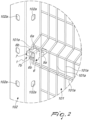
- the reference numeral 1 generally designates an anchoring assembly for enclosures 100.
- the fencing 100 is intended to be deployed along a perimeter of interest, typically in an industrial building, in order to delimit a specific area and prevent or in any case control access to it, for example to guard against or reduce the risk that individuals could accidentally come into contact with potentially hazardous machinery or that, conversely, the individuals themselves could damage sophisticated and delicate machinery. It is emphasized however that the purposes for which the barrier 100 is deployed along the perimeter of interest may be any, while remaining within the scope of protection claimed herein.
- the fencing 100 with which the assembly 1 is intended to be used comprises first of all at least one laminar screen 101, which has at least one rigid wire 101a, and at least one post 102, for supporting the screen 101 with vertical orientation.
- the screen 101 can indeed be positioned, vertically, facing and proximate to the machinery or in any case along the perimeter of interest, on the perimeter of the area to be delimited.
- the fencing 100 will be provided with at least two posts 102, which, as in the accompanying Figure 1 , support the screen 101 at each side (at a respective wire 101a).
- the possibility is not ruled out however of using a single post 102 associated with one side of the screen 101, the other side being supported by a different structure.
- the screen 101 is constituted by a grille of rigid wires 101a (or bars, or the like), which are made for example of iron or other metallic materials or even of a polymeric material.
- the anchoring assembly 1 typically acts on the outermost vertical wire 101a (as in the accompanying figures), but the possibility is not ruled out of having it interact with another vertical wire 101a (for example one of the next innermost ones) or even with a horizontal wire 101a.
- the screen 101 can also have a different structure, for example comprising a panel provided with a single wire 101a on a side, in order to allow interaction with the assembly 1.
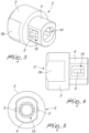
- the assembly 1 comprises at least one pin 2 (shown specifically in Figures 2-4 ) which is provided with a head 3 and a shank 4.
- the shank 4 is configured to be inserted into a hole 102a which is provided along the post 102, until the head 3 abuts on the post 102 and an end portion of that shank 4 exits on the opposite side.
- the transverse cross-section of the shank 4 is chosen to be of such dimensions as to allow insertion into the hole 102a, while this insertion of the head 3 is prevented, which has an enlarged transverse cross-section (with respect to the shank 4 and to the hole 102a).
- the length of the shank 4 (measured along the ideal direction of insertion into the hole 102a) is such that when the head 3 abuts against the post 102, the shank 4 exits partially from the other side with an end portion thereof (the length of which can constitute a fraction of extent chosen at will with respect to the overall length of the shank 4).
- numerous holes 102a are provided along the post 102.
- the pin 2 has (a variable number of) lateral tabs 5 that can move elastically between a non-deformed configuration, in which they protrude from the lateral surface of the end portion of the shank 4 ( Figure 5 ), and at least one deformed configuration, in which they are kept inside the transverse space occupation of the shank 4.
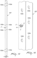
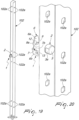
- the tabs 5 are therefore arranged at a longitudinal height (with respect to the ideal direction of insertion into the hole 102a) such that, when the head 3 abuts against the post 102, they protrude from the shank 4 at the other side of the latter and therefore they oppose any extraction of the pin 2, thus guarding against its accidental loss ( Figures 14 and 16 for example).
- each tab 5 forms externally a form of outward-inclined ramp ( Figure 3 ), which abuts against the rim of the hole 102a during insertion and guards against the danger of excessively straining the tab 5 (or the rim of the hole 102a).
- Figure 3 shows a solution in which the shank 4 is provided with two tabs 5, but there can be any number of tabs 5.
- the assembly 1 further comprises at least one clamp which in turn comprises a first jaw 6 and a second jaw 7 ( Figures 6-10 for example).
- the second jaw 7 can be abutted with a base surface 7a thereof against the post 102 and has a recess 8 therealong ( Figures 6, 7 , 9, 10 for example) which is configured to receive the shank 4 (the end portion of it) with interference. So in fact, after the shank 4 has been inserted into the hole 102a, the second jaw 7 can be abutted (on the opposite side to the head 3) against the post 102, taking care to force the insertion of the shank 4 (the end portion) into the recess 8.
- the coupling with interference impedes the subsequent disengagement and therefore, in a manner similar to the tabs 5, guards against accidental loss.
- the rigid wire 101a can be clamped between the jaws 6, 7, in a position that is spaced apart from the base surface 7a (and therefore from the post 102).
- the jaws 6, 7 are shaped so that, when they are brought together and mutually tightened, the respective areas for receiving and retaining the wire 101a are spaced apart from the base surface 7a (and from the post 102).
- the assembly 1 also comprises at least one at least partially threaded stem 9, which can be inserted into the jaws 6, 7 and into the shank 4 until it is screwed into a female thread which is provided inside the pin 2 (and preferably inside its head 3), with consequent mutual tightening of the jaws 6, 7 and clamping in place of the rigid wire 101a.
- the insertion and therefore the screwing of the stem 9 respectively into the jaws 6, 7 and into the pin 2 obtain a plurality of results, enabling the assembly 1 to achieve the set aim.
- the stem 9 (with its enlarged tip 9a) makes the jaws 6, 7 approach each other until they are mutually tightened, thus enabling the clamping in place of the wire 101a.
- the stem 9 is introduced into the female thread and so locks the jaws 6, 7 (and with them the wire 101a) to the post 102, in so doing obtaining the mutual anchoring of the latter and of the screen 101, thus ensuring the possibility of assembling the fencing 100.
- the recess 8 has (preferably but not exclusively) a shape that is substantially complementary to that of the shank 4 (at least of its end portion). Furthermore, the recess 8 is provided, along its lateral surface, with a plurality of protrusions 10, for determining the reception with interference of the shank 4 in the recess 8. The possibility is not ruled out however of obtaining the coupling (the reception) with interference according to other practical methods, which in any case remain within the scope of protection claimed herein.
- each protrusion 10 is constituted substantially by an elongated ridge, which extends along the ideal direction of insertion of the shank 4 into the recess 8.
- the recess 8 is provided with six ridges (protrusions 10), which are mutually parallel and distributed along the lateral surface of the recess 8.
- protrusions 10 six ridges (protrusions 10), which are mutually parallel and distributed along the lateral surface of the recess 8.
- assemblies 1 that comprise any number of ridges, and/or other types of protrusions 10.
- the second jaw 7 comprises a block 7b which is provided with the base surface 7a.
- the block 7b is passed through by a through passage which defines, with one end portion, the recess 8 and is configured (is chosen to be of suitable dimensions) in order to allow the insertion of the stem 9.
- the block 7b has, in an upward region and in a downward region, wedge-shaped side walls, so as not to present horizontally-arranged surfaces when assembly of the fencing 100 is complete.
- the block 7b has a lateral groove 11, which is configured to accommodate a length of the wire 101a.
- the groove 11 will also preferably have a circular/curvilinear bottom or progression, but the possibility is not ruled out in any case of adopting different shapes (for example a flat bottom), for wires 101a both with a circular cross-section and with another cross-section.
- the wire 101a is accommodated in a groove 11 which is arranged in a substantially intermediate position along the side of the block 7b. The possibility is not ruled out however of also receiving the wire 101a on the base of the block 7b opposite from the base surface 7a (so that the wire 101a is still kept spaced apart from the base surface 7a and from the post 102).
- the first jaw 6 comprises a plate 6a, which can be applied to (pressed on) the second jaw 7 on the opposite side to the base surface 7a, by the action of the stem 9 (and of its tip 9a in particular), which can be inserted into a respective through orifice 12 provided along that plate 6a (until the tip 9a abuts against the latter).
- the first jaw 6 further comprises at least one raised lug 6b, which extends substantially perpendicular from a margin of the plate 6a and has an indentation 13 (clearly visible for example in Figures 6-8 ), which is configured to accommodate a length of the wire 101a (different from the one that goes into the groove 11). Therefore, when the jaws 6, 7 are mutually tightened, against the wire 101a (against respective lengths) one flank (and/or the bottom) of the groove 11 press on one side, and the bottom (and/or one flank) of the indentation 13 press on the other side, so achieving the desired clamping in place by friction.
- the profile of the indentation 13 can also preferably be chosen to be circular or in any case curvilinear, but other possibilities are not ruled out.
- the first jaw 6 comprises two (or even more) lugs 6b, which extend from two mutually opposite margins of the plate 6a and which have respective indentations 13 (for corresponding lengths of the wire 101a).
- the head 3 of the pin 2 has a substantially cylindrical shape structure and is provided with two flattened-out lateral features 3a, in order to allow facilitated interaction with a manipulation tool (if required).
- the shank 4 is constituted substantially by a hollow sleeve, which defines internally a channel 14 which is coaxially arranged in communication with the female thread of the head 3 (the female thread is not shown in the accompanying figures but its placement is entirely intuitive for a person skilled in the art in light of what has been explained up to this point). It is therefore the channel 14 that receives the stem 9, which is already inserted into the orifice 12 and into the through passage of the block 7b, in order to allow the coupling of the jaws 6, 7 to the pin 2.
- each tab 5 is elastically appended to an edge of a respective window 15, which is provided in a corresponding flattened-out portion of the lateral surface of the end portion of the shank 4.
- Each window 15 is effectively facing the channel 14 and when the tabs 5 are pushed toward the deformed configuration, they tend to return toward the channel 14.
- a fencing 100 that comprises at least one laminar screen 101, which is provided with at least one rigid wire 101a, and at least one post 102, for supporting the screen 101 with vertical orientation.
- the fencing 100 according to the invention therefore comprises an anchoring assembly 1 according to what is shown in the foregoing pages.
- kit composed of a screen 101, a post 102 (or rather two posts 102) and one or more assemblies 1 that ensure their mutual anchor point effectively constitutes a basic modular unit, which can be repeated when desired to form enclosures 100 (which in any case remain within the scope of protection claimed herein) that are adapted to delimit areas with any perimeter, in terms of both shape and of dimensions (each post 102 can be associated with two or even more screens 101, side-by-side).
- kits for providing (assembling) enclosures 100 which comprises a plurality of laminar screens 101, each having at least one rigid wire 101a, a plurality of posts 102, each one for supporting at least one respective screen 101 with vertical orientation, and a plurality of anchoring assemblies 1 according to what is already explained in the foregoing pages.
- the installation technician can therefore find the screens 101 to be distributed as desired along the perimeter of interest, and also the posts 102 to be used to support them and the assemblies 1 for obtaining the anchoring.
- the tabs 5 are elastically deformed, automatically, in order to return later to the non-deformed configuration and oppose the subsequent extraction (which can happen only by pressing on the tabs 5).
- the second jaw 7 can be abutted with its base surface 7a against the post 102, so that the shank 4 (its end portion) is inserted into the recess 8.
- the coupling with interference guards against the danger that the second jaw 7 might accidentally detach (disengagement can occur only by forcing the detachment of the second jaw 7).
- the stem 9 needs to be inserted first into the orifice 12 of the first jaw 6 (of the first plate 6a), and then into the through passage of the second jaw 7 and into the channel 14 of the shank 4, and then it is screwed with a tool into the female thread provided in the pin 2.
- the two jaws 6, 7 are mutually tightened (immobilizing the wire 101a between the groove 11 and the indentation 13), while the clamp (the jaws 6, 7 themselves) is in turn firmly pinioned to the pin 2.
- Such anchoring point can be removed only by using a tool to unscrew the pin 2.
- each assembly 1 acts on one of the outer (vertical) wires 101a of the screen 101.
- the jaws can interact with a more inner vertical wire 101a.
- the jaws can be deployed to clamp a horizontal wire 101a.
- the assembly 1 makes it possible to assemble a fencing 1 in a practical and rapid manner (by mutually coupling each screen 101 and the respective posts 102), by carrying out a few simple steps of short duration.
- the wire 101a (and in general the screen 101) is kept at a distance from the post 102 and therefore in the fencing 100 according to the invention the zones of contact between different components are reduced to a small number (they are reduced effectively to the base surface 7a, which is of limited extent, and very little else).
- the wire 101a is in turn clamped only at small lengths which are trapped between the jaws 6, 7.
- the block 7b preferably does not present horizontal surfaces (nor does the totality of the assembly 1, or the near-totality).
- both the areas in mutual contact and the horizontal surfaces are therefore very reduced, and this makes them easily washable and more generally fully adapted for use in buildings intended to be used in the food sector.
- the assembly 1 according to the invention is of the captive type, in that it is provided with contrivances (the tabs 5 and the protrusions 10 in particular) that are adapted to reduce or eliminate the risk of accidental disengagement and/or loss of its components.
- the complete clamping in place (and release, if any) of the wire 101a can be done only with a tool (a wrench or a screwdriver) with which to cause the screwing or unscrewing of the stem 9.
- the materials employed, as well as the dimensions, may be any according to requirements and to the state of the art.
Landscapes
- Engineering & Computer Science (AREA)
- Architecture (AREA)
- Civil Engineering (AREA)
- Structural Engineering (AREA)
- Fencing (AREA)
- Devices Affording Protection Of Roads Or Walls For Sound Insulation (AREA)
Claims (13)
- Eine Verankerungsanordnung für Umzäunungen (100), die mindestens ein laminares Gitter (101) umfassen, das mindestens einen starren Draht (101a) hat, und mindestens einen Pfosten (102) zum Tragen des Gitters (101) mit vertikaler Ausrichtung, wobei die Verankerungsanordnung mindestens Folgendes umfasst:- einen Stift (2), ausgestattet mit einem Kopf (3) und mit einem Schaft (4), wobei der Schaft einen transversalen Platzbedarf hat und ausgebildet ist, um in ein Loch (102a) eingesetzt zu werden, das entlang dem Pfosten (102) angebracht ist, bis der Kopf (3) an den Pfosten (102) anstößt und ein Endabschnitt des Schafts (4) auf der gegenüberliegenden Seite des Pfostens austritt;wobei der Stift (2) seitliche Vorsprünge (5) hat, die sich elastisch zwischen einer nicht verformten Konfiguration, in welcher sie von der Seitenfläche des Endabschnitts des Schafts (4) vorstehen, und mindestens einer verformten Konfiguration bewegen können, in der sie innerhalb des transversalen Platzbedarfs des Schafts (4) gehalten werden,dadurch gekennzeichnet, dass die Verankerungsanordnung weiter Folgendes umfasst:- eine Klemme, die eine erste Backe (6) und eine zweite Backe (7) umfasst, wobei die zweite Backe (7) in der Lage ist, mit einer Grundfläche (7a) derselben am Pfosten (102) anzuliegen, und eine Vertiefung (8) entlang der Grundfläche (7a) hat, die ausgebildet ist, um den Schaft (4) mit Presspassung aufzunehmen, wobei es möglich ist, den starren Draht (101a) in einer Position zu klemmen, die von der Grundfläche (7a) beabstandet ist, zwischen den Backen (6, 7), die mit Bezug aufeinander festgezogen sind;- einen zumindest teilweise mit einem Gewinde versehenen Schaft (9), der in die Backen (6, 7) und in den Schaft (4) eingeführt werden kann, bis er in ein Innengewinde eingeschraubt wird, das innerhalb des Stifts (2) angebracht ist, mit daraus folgendem gegenseitigen Festziehen der Backen (6, 7) und Festklemmen des starren Drahts (101a).
- Die Verankerungsanordnung gemäß Anspruch 1, dadurch gekennzeichnet, dass die Vertiefung (8) eine Form hat, die im Wesentlichen zu derjenigen des Schafts (4) komplementär und entlang ihrer Seitenfläche mit einer Vielzahl von Vorsprüngen (10) für die Aufnahme des Schafts (4) in der Vertiefung (8) mit Presspassung ausgestattet ist.
- Die Verankerungsanordnung gemäß Anspruch 2, dadurch gekennzeichnet, dass jeder der Vorsprünge (10) im Wesentlichen in einem verlängerten Grat besteht, welcher sich entlang der idealen Einführrichtung des Schafts (4) in die Vertiefung (8) erstreckt.
- Die Verankerungsanordnung gemäß Anspruch 3, dadurch gekennzeichnet, dass die Vertiefung (8) sechs Grate hat, die zueinander parallel und entlang der Seitenfläche der Vertiefung (8) verteilt sind.
- Die Verankerungsanordnung gemäß einem oder mehreren der obigen Ansprüche, dadurch gekennzeichnet, dass die zweite Backe (7) einen Block (7b) umfasst, der die Grundfläche (7a) präsentiert, wobei der Block (7b) von einem Durchgang durchquert ist, welcher mit einem Endabschnitt die Vertiefung (8) bestimmt und zum Einführen des Schafts (9) ausgebildet ist.
- Die Verankerungsanordnung gemäß Anspruch 5, dadurch gekennzeichnet, dass der Block (7b) mit einer seitlichen Nut (11) versehen ist, die ausgebildet ist, um eine Länge des Drahts (101a) aufzunehmen.
- Die Verankerungsanordnung gemäß einem oder mehreren der obigen Ansprüche, dadurch gekennzeichnet, dass die erste Backe (6) eine Platte (6a) umfasst, die an der zweiten Backe (7), an der Seite, die der Grundfläche (7a) gegenüberliegt, mit Hilfe des Schafts (9) angebracht werden kann, welcher in eine entsprechende Durchgangsöffnung (12) eingeführt werden kann, die entlang der Platte (6a) angebracht ist, wobei die erste Backe (6) mindestens eine erhöhte Lasche (6b) umfasst, die sich im Wesentlichen senkrecht von einem Rand der Platte (6a) erstreckt und eine Ausbuchtung (13) hat, welche ausgebildet ist, um eine Länge des Drahts (101a) aufzunehmen.
- Die Verankerungsanordnung gemäß Anspruch 7, dadurch gekennzeichnet, dass die erste Backe (6) zwei Laschen (6b) umfasst, die sich von den zwei einander gegenüberliegenden Rändern der Platte (6a) erstrecken und die dazugehörigen Ausbuchtungen (13) haben.
- Die Verankerungsanordnung gemäß einem oder mehreren der obigen Ansprüche, dadurch gekennzeichnet, dass der Kopf (3) des Stifts (2) eine im Wesentlichen zylindrische Form hat und zur leichteren Interaktion mit einem Arbeitswerkzeug mit zwei abgeflachten Seitenflächen (3a) versehen ist.
- Die Verankerungsanordnung gemäß einem oder mehreren der obigen Ansprüche, dadurch gekennzeichnet, dass der Schaft (4) im Wesentlichen aus einer hohlen Buchse besteht, die in ihrem Inneren einen Kanal (14) bestimmt, welcher koaxial in Kommunikation mit dem Innengewinde des Kopfs (3) angeordnet ist.
- Die Verankerungsanordnung gemäß einem oder mehreren der obigen Ansprüche, dadurch gekennzeichnet, dass jeder der Vorsprünge (5) elastisch an eine Kante eines entsprechenden Fensters (15) angehängt ist, welches in einem entsprechenden abgeflachten Abschnitt der Seitenfläche des Endabschnitts des Schafts (4) angebracht ist.
- Eine Umzäunung, die mindestens ein laminares Gitter (101) umfasst, das mindestens einen starren Draht (101a) hat, und mindestens einen Pfosten (102) zum Tragen des Gitters (101) mit vertikaler Ausrichtung, dadurch gekennzeichnet, dass sie mindestens eine Verankerungsanordnung (1) gemäß einem oder mehreren der obigen Ansprüche umfasst.
- Ein Bausatz zur Produktion von Umzäunungen (100), dadurch gekennzeichnet, dass er eine Vielzahl laminarer Gitter (101) umfasst, die jeweils mindestens einen starren Draht (101a), eine Vielzahl von Pfosten (102), jeweils zum Tragen mindestens eines Gitters (101) mit vertikaler Ausrichtung, und eine Vielzahl von Verankerungsanordnungen (1) gemäß einem oder mehreren der obigen Ansprüche 1-11 haben.
Applications Claiming Priority (1)
| Application Number | Priority Date | Filing Date | Title |
|---|---|---|---|
| PCT/IT2019/000034 WO2020230173A1 (en) | 2019-05-14 | 2019-05-14 | Anchoring assembly and associated fencing |
Publications (2)
| Publication Number | Publication Date |
|---|---|
| EP3969693A1 EP3969693A1 (de) | 2022-03-23 |
| EP3969693B1 true EP3969693B1 (de) | 2023-05-31 |
Family
ID=70968978
Family Applications (1)
| Application Number | Title | Priority Date | Filing Date |
|---|---|---|---|
| EP19891688.4A Active EP3969693B1 (de) | 2019-05-14 | 2019-05-14 | Verankerungsanordnung und zugehörige umzäunung |
Country Status (5)
| Country | Link |
|---|---|
| US (1) | US12006720B2 (de) |
| EP (1) | EP3969693B1 (de) |
| CA (1) | CA3137655A1 (de) |
| ES (1) | ES2949669T3 (de) |
| WO (1) | WO2020230173A1 (de) |
Families Citing this family (6)
| Publication number | Priority date | Publication date | Assignee | Title |
|---|---|---|---|---|
| PT3620592T (pt) * | 2018-09-10 | 2021-01-20 | Tradartiklar I Hillerstorp Ab | Painel de rede e um sistema de barreira de segurança |
| EP4405541A1 (de) * | 2021-09-22 | 2024-07-31 | Worxsafe AB | Gitterplattenhalter |
| US11905725B1 (en) * | 2022-01-06 | 2024-02-20 | Ameristar Perimeter Security Usa Inc. | Connector |
| US12607036B2 (en) * | 2023-05-10 | 2026-04-21 | Honeywell Safety Products Usa, Inc. | Edge protection barrier separate handrail |
| GB2643452A (en) * | 2024-08-16 | 2026-02-18 | First Fence Ltd | Profence clamp |
| US20260146470A1 (en) * | 2024-11-25 | 2026-05-28 | Melon Dash | Yielding fence system with selectively lockable pivotal panels |
Family Cites Families (15)
| Publication number | Priority date | Publication date | Assignee | Title |
|---|---|---|---|---|
| DE3937791C1 (en) | 1989-11-14 | 1991-05-02 | Horst 4630 Bochum De Klostermann | Fastener for fence wire mesh sections - is in form of expansion dowel snapped into bore in fence post |
| BE1007664A3 (nl) * | 1993-10-21 | 1995-09-05 | Bekaert Sa Nv | Afsluiting met stavenpanelen. |
| DE4436345C1 (de) * | 1994-10-12 | 1996-02-08 | V & S Sicherungssysteme Gmbh & | Gitterzaun mit einrastenden Haltebügeln |
| US5746040A (en) * | 1996-08-20 | 1998-05-05 | Wireway/Husky Corp. | Modular wall construction |
| US6010116A (en) * | 1997-11-14 | 2000-01-04 | Knott, Sr.; James M. | High security fence assembly |
| FR2856717B1 (fr) | 2003-06-25 | 2005-09-23 | Landaise De Profilage Acier So | Dispositif de fixation de panneaux de treillis soudes sur un poteau |
| WO2008154661A2 (en) * | 2007-06-15 | 2008-12-18 | Richard Bruce Cochrane | Barrier |
| AU2009248435B9 (en) * | 2007-06-18 | 2013-09-19 | Clipex Fencing Holdings Limited | A Fence Post Assembly |
| DE202010005989U1 (de) * | 2010-04-21 | 2011-08-04 | Legi Gmbh | Verbindung von zwei Gittertafeln |
| AU2011100489B4 (en) * | 2010-12-15 | 2011-08-11 | Pro3 Safety Pty Ltd | System and components for safely enclosing handrails, stairways, walkways and platforms |
| DE102013004915B4 (de) * | 2013-03-22 | 2017-01-26 | Fuat Celik | Vorrichtung zur Befestigung von Zaunmatten an Zaunpfählen |
| BE1021258B1 (nl) * | 2014-05-27 | 2015-10-07 | Betafence Holding Nv | Omheininggaas, omheining en werkwijze voor het vervaardigen van een omheininggaas |
| US20160083974A1 (en) * | 2014-09-22 | 2016-03-24 | L&P Property Management Company | Structure for assembling and disassembling partition members |
| EP3045616B1 (de) * | 2015-01-15 | 2019-03-13 | Grupo Carlos Serrano Vicario, S.L. | Halter für Metallpfosten |
| EP3839174B1 (de) * | 2019-12-19 | 2023-07-26 | Troax AB | Halterung zur stützung eines wandelementes und system zur abschirmung eines bereichs |
-
2019
- 2019-05-14 EP EP19891688.4A patent/EP3969693B1/de active Active
- 2019-05-14 WO PCT/IT2019/000034 patent/WO2020230173A1/en not_active Ceased
- 2019-05-14 ES ES19891688T patent/ES2949669T3/es active Active
- 2019-05-14 CA CA3137655A patent/CA3137655A1/en active Pending
- 2019-05-14 US US17/611,437 patent/US12006720B2/en active Active
Also Published As
| Publication number | Publication date |
|---|---|
| ES2949669T3 (es) | 2023-10-02 |
| US12006720B2 (en) | 2024-06-11 |
| EP3969693A1 (de) | 2022-03-23 |
| WO2020230173A1 (en) | 2020-11-19 |
| CA3137655A1 (en) | 2020-11-19 |
| US20220259888A1 (en) | 2022-08-18 |
Similar Documents
| Publication | Publication Date | Title |
|---|---|---|
| US12006720B2 (en) | Anchoring assembly and associated fencing | |
| US20240305078A1 (en) | Wire Clamp | |
| WO2016081934A2 (en) | Shelf frame assembly system | |
| RU2317764C2 (ru) | Система, зажимной элемент и запирающий элемент для соединения профильных элементов | |
| AU2018215376B2 (en) | Securing assembly | |
| EP3194797B1 (de) | Befestigungsvorrichtung | |
| US20180142870A1 (en) | Push-on mechanical fastener for lighting fixture | |
| EP4050175B1 (de) | Zwischendeckensystem | |
| JPH06229096A (ja) | キャリア組立て体 | |
| EP2498356B1 (de) | Diebstahlsicherungsvorrichtung für ein an der Wand befestigbares System | |
| EP3045616A1 (de) | Halter für metallpfosten | |
| EP4368791B1 (de) | Klemme | |
| WO2017175659A1 (ja) | 吊りボルト支持金具 | |
| EP1422800B1 (de) | Geräteträger zur Befestigung von Geräten auf eine aussen oder innen isolierte Gebäudefassade oder Gebäudemauer | |
| KR102646241B1 (ko) | 메쉬 펜스용 가림막 고정 장치 | |
| EP3708742A2 (de) | Fester schutz mit verbesserten montagemitteln | |
| EP1788168A1 (de) | Verbindungsvorrichtung | |
| JPS62260956A (ja) | 手摺笠木装置 | |
| JP2017190660A (ja) | 吊りボルト支持金具 | |
| JPH0730805Y2 (ja) | ボルト螺合具及びボルト螺合装置 | |
| GB2356491A (en) | Improved fittings | |
| HK1231628B (en) | Fence post insulator for electrifiable plastic coated wire | |
| KR20050114865A (ko) | 책상용 간격조절구의 설치구조물 | |
| JPH0538204U (ja) | 工事現場囲壁の支持用補助具 |
Legal Events
| Date | Code | Title | Description |
|---|---|---|---|
| STAA | Information on the status of an ep patent application or granted ep patent |
Free format text: STATUS: UNKNOWN |
|
| STAA | Information on the status of an ep patent application or granted ep patent |
Free format text: STATUS: THE INTERNATIONAL PUBLICATION HAS BEEN MADE |
|
| PUAI | Public reference made under article 153(3) epc to a published international application that has entered the european phase |
Free format text: ORIGINAL CODE: 0009012 |
|
| STAA | Information on the status of an ep patent application or granted ep patent |
Free format text: STATUS: REQUEST FOR EXAMINATION WAS MADE |
|
| 17P | Request for examination filed |
Effective date: 20210929 |
|
| AK | Designated contracting states |
Kind code of ref document: A1 Designated state(s): AL AT BE BG CH CY CZ DE DK EE ES FI FR GB GR HR HU IE IS IT LI LT LU LV MC MK MT NL NO PL PT RO RS SE SI SK SM TR |
|
| DAV | Request for validation of the european patent (deleted) | ||
| DAX | Request for extension of the european patent (deleted) | ||
| GRAP | Despatch of communication of intention to grant a patent |
Free format text: ORIGINAL CODE: EPIDOSNIGR1 |
|
| STAA | Information on the status of an ep patent application or granted ep patent |
Free format text: STATUS: GRANT OF PATENT IS INTENDED |
|
| INTG | Intention to grant announced |
Effective date: 20221219 |
|
| GRAS | Grant fee paid |
Free format text: ORIGINAL CODE: EPIDOSNIGR3 |
|
| GRAA | (expected) grant |
Free format text: ORIGINAL CODE: 0009210 |
|
| STAA | Information on the status of an ep patent application or granted ep patent |
Free format text: STATUS: THE PATENT HAS BEEN GRANTED |
|
| AK | Designated contracting states |
Kind code of ref document: B1 Designated state(s): AL AT BE BG CH CY CZ DE DK EE ES FI FR GB GR HR HU IE IS IT LI LT LU LV MC MK MT NL NO PL PT RO RS SE SI SK SM TR |
|
| REG | Reference to a national code |
Ref country code: GB Ref legal event code: FG4D Ref country code: CH Ref legal event code: EP |
|
| REG | Reference to a national code |
Ref country code: AT Ref legal event code: REF Ref document number: 1570996 Country of ref document: AT Kind code of ref document: T Effective date: 20230615 Ref country code: DE Ref legal event code: R096 Ref document number: 602019029652 Country of ref document: DE |
|
| REG | Reference to a national code |
Ref country code: IE Ref legal event code: FG4D |
|
| REG | Reference to a national code |
Ref country code: SE Ref legal event code: TRGR |
|
| P01 | Opt-out of the competence of the unified patent court (upc) registered |
Effective date: 20230528 |
|
| REG | Reference to a national code |
Ref country code: NL Ref legal event code: FP |
|
| REG | Reference to a national code |
Ref country code: LT Ref legal event code: MG9D |
|
| REG | Reference to a national code |
Ref country code: ES Ref legal event code: FG2A Ref document number: 2949669 Country of ref document: ES Kind code of ref document: T3 Effective date: 20231002 |
|
| REG | Reference to a national code |
Ref country code: AT Ref legal event code: MK05 Ref document number: 1570996 Country of ref document: AT Kind code of ref document: T Effective date: 20230531 |
|
| PG25 | Lapsed in a contracting state [announced via postgrant information from national office to epo] |
Ref country code: NO Free format text: LAPSE BECAUSE OF FAILURE TO SUBMIT A TRANSLATION OF THE DESCRIPTION OR TO PAY THE FEE WITHIN THE PRESCRIBED TIME-LIMIT Effective date: 20230831 Ref country code: AT Free format text: LAPSE BECAUSE OF FAILURE TO SUBMIT A TRANSLATION OF THE DESCRIPTION OR TO PAY THE FEE WITHIN THE PRESCRIBED TIME-LIMIT Effective date: 20230531 |
|
| PG25 | Lapsed in a contracting state [announced via postgrant information from national office to epo] |
Ref country code: RS Free format text: LAPSE BECAUSE OF FAILURE TO SUBMIT A TRANSLATION OF THE DESCRIPTION OR TO PAY THE FEE WITHIN THE PRESCRIBED TIME-LIMIT Effective date: 20230531 Ref country code: PL Free format text: LAPSE BECAUSE OF FAILURE TO SUBMIT A TRANSLATION OF THE DESCRIPTION OR TO PAY THE FEE WITHIN THE PRESCRIBED TIME-LIMIT Effective date: 20230531 Ref country code: LV Free format text: LAPSE BECAUSE OF FAILURE TO SUBMIT A TRANSLATION OF THE DESCRIPTION OR TO PAY THE FEE WITHIN THE PRESCRIBED TIME-LIMIT Effective date: 20230531 Ref country code: LT Free format text: LAPSE BECAUSE OF FAILURE TO SUBMIT A TRANSLATION OF THE DESCRIPTION OR TO PAY THE FEE WITHIN THE PRESCRIBED TIME-LIMIT Effective date: 20230531 Ref country code: IS Free format text: LAPSE BECAUSE OF FAILURE TO SUBMIT A TRANSLATION OF THE DESCRIPTION OR TO PAY THE FEE WITHIN THE PRESCRIBED TIME-LIMIT Effective date: 20230930 Ref country code: HR Free format text: LAPSE BECAUSE OF FAILURE TO SUBMIT A TRANSLATION OF THE DESCRIPTION OR TO PAY THE FEE WITHIN THE PRESCRIBED TIME-LIMIT Effective date: 20230531 Ref country code: GR Free format text: LAPSE BECAUSE OF FAILURE TO SUBMIT A TRANSLATION OF THE DESCRIPTION OR TO PAY THE FEE WITHIN THE PRESCRIBED TIME-LIMIT Effective date: 20230901 |
|
| PG25 | Lapsed in a contracting state [announced via postgrant information from national office to epo] |
Ref country code: FI Free format text: LAPSE BECAUSE OF FAILURE TO SUBMIT A TRANSLATION OF THE DESCRIPTION OR TO PAY THE FEE WITHIN THE PRESCRIBED TIME-LIMIT Effective date: 20230531 |
|
| PG25 | Lapsed in a contracting state [announced via postgrant information from national office to epo] |
Ref country code: SK Free format text: LAPSE BECAUSE OF FAILURE TO SUBMIT A TRANSLATION OF THE DESCRIPTION OR TO PAY THE FEE WITHIN THE PRESCRIBED TIME-LIMIT Effective date: 20230531 |
|
| PG25 | Lapsed in a contracting state [announced via postgrant information from national office to epo] |
Ref country code: SM Free format text: LAPSE BECAUSE OF FAILURE TO SUBMIT A TRANSLATION OF THE DESCRIPTION OR TO PAY THE FEE WITHIN THE PRESCRIBED TIME-LIMIT Effective date: 20230531 Ref country code: SK Free format text: LAPSE BECAUSE OF FAILURE TO SUBMIT A TRANSLATION OF THE DESCRIPTION OR TO PAY THE FEE WITHIN THE PRESCRIBED TIME-LIMIT Effective date: 20230531 Ref country code: RO Free format text: LAPSE BECAUSE OF FAILURE TO SUBMIT A TRANSLATION OF THE DESCRIPTION OR TO PAY THE FEE WITHIN THE PRESCRIBED TIME-LIMIT Effective date: 20230531 Ref country code: PT Free format text: LAPSE BECAUSE OF FAILURE TO SUBMIT A TRANSLATION OF THE DESCRIPTION OR TO PAY THE FEE WITHIN THE PRESCRIBED TIME-LIMIT Effective date: 20231002 Ref country code: EE Free format text: LAPSE BECAUSE OF FAILURE TO SUBMIT A TRANSLATION OF THE DESCRIPTION OR TO PAY THE FEE WITHIN THE PRESCRIBED TIME-LIMIT Effective date: 20230531 Ref country code: DK Free format text: LAPSE BECAUSE OF FAILURE TO SUBMIT A TRANSLATION OF THE DESCRIPTION OR TO PAY THE FEE WITHIN THE PRESCRIBED TIME-LIMIT Effective date: 20230531 Ref country code: CZ Free format text: LAPSE BECAUSE OF FAILURE TO SUBMIT A TRANSLATION OF THE DESCRIPTION OR TO PAY THE FEE WITHIN THE PRESCRIBED TIME-LIMIT Effective date: 20230531 |
|
| REG | Reference to a national code |
Ref country code: DE Ref legal event code: R097 Ref document number: 602019029652 Country of ref document: DE |
|
| PLBE | No opposition filed within time limit |
Free format text: ORIGINAL CODE: 0009261 |
|
| STAA | Information on the status of an ep patent application or granted ep patent |
Free format text: STATUS: NO OPPOSITION FILED WITHIN TIME LIMIT |
|
| PG25 | Lapsed in a contracting state [announced via postgrant information from national office to epo] |
Ref country code: SI Free format text: LAPSE BECAUSE OF FAILURE TO SUBMIT A TRANSLATION OF THE DESCRIPTION OR TO PAY THE FEE WITHIN THE PRESCRIBED TIME-LIMIT Effective date: 20230531 |
|
| 26N | No opposition filed |
Effective date: 20240301 |
|
| PG25 | Lapsed in a contracting state [announced via postgrant information from national office to epo] |
Ref country code: SI Free format text: LAPSE BECAUSE OF FAILURE TO SUBMIT A TRANSLATION OF THE DESCRIPTION OR TO PAY THE FEE WITHIN THE PRESCRIBED TIME-LIMIT Effective date: 20230531 |
|
| PG25 | Lapsed in a contracting state [announced via postgrant information from national office to epo] |
Ref country code: BG Free format text: LAPSE BECAUSE OF FAILURE TO SUBMIT A TRANSLATION OF THE DESCRIPTION OR TO PAY THE FEE WITHIN THE PRESCRIBED TIME-LIMIT Effective date: 20230531 |
|
| PG25 | Lapsed in a contracting state [announced via postgrant information from national office to epo] |
Ref country code: BG Free format text: LAPSE BECAUSE OF FAILURE TO SUBMIT A TRANSLATION OF THE DESCRIPTION OR TO PAY THE FEE WITHIN THE PRESCRIBED TIME-LIMIT Effective date: 20230531 |
|
| REG | Reference to a national code |
Ref country code: CH Ref legal event code: PL |
|
| PG25 | Lapsed in a contracting state [announced via postgrant information from national office to epo] |
Ref country code: MC Free format text: LAPSE BECAUSE OF FAILURE TO SUBMIT A TRANSLATION OF THE DESCRIPTION OR TO PAY THE FEE WITHIN THE PRESCRIBED TIME-LIMIT Effective date: 20230531 |
|
| PG25 | Lapsed in a contracting state [announced via postgrant information from national office to epo] |
Ref country code: LU Free format text: LAPSE BECAUSE OF NON-PAYMENT OF DUE FEES Effective date: 20240514 |
|
| PG25 | Lapsed in a contracting state [announced via postgrant information from national office to epo] |
Ref country code: MC Free format text: LAPSE BECAUSE OF FAILURE TO SUBMIT A TRANSLATION OF THE DESCRIPTION OR TO PAY THE FEE WITHIN THE PRESCRIBED TIME-LIMIT Effective date: 20230531 Ref country code: LU Free format text: LAPSE BECAUSE OF NON-PAYMENT OF DUE FEES Effective date: 20240514 Ref country code: CH Free format text: LAPSE BECAUSE OF NON-PAYMENT OF DUE FEES Effective date: 20240531 |
|
| REG | Reference to a national code |
Ref country code: BE Ref legal event code: MM Effective date: 20240531 |
|
| PG25 | Lapsed in a contracting state [announced via postgrant information from national office to epo] |
Ref country code: IE Free format text: LAPSE BECAUSE OF NON-PAYMENT OF DUE FEES Effective date: 20240514 |
|
| PG25 | Lapsed in a contracting state [announced via postgrant information from national office to epo] |
Ref country code: BE Free format text: LAPSE BECAUSE OF NON-PAYMENT OF DUE FEES Effective date: 20240531 |
|
| PG25 | Lapsed in a contracting state [announced via postgrant information from national office to epo] |
Ref country code: CY Free format text: LAPSE BECAUSE OF FAILURE TO SUBMIT A TRANSLATION OF THE DESCRIPTION OR TO PAY THE FEE WITHIN THE PRESCRIBED TIME-LIMIT; INVALID AB INITIO Effective date: 20190514 |
|
| PG25 | Lapsed in a contracting state [announced via postgrant information from national office to epo] |
Ref country code: HU Free format text: LAPSE BECAUSE OF FAILURE TO SUBMIT A TRANSLATION OF THE DESCRIPTION OR TO PAY THE FEE WITHIN THE PRESCRIBED TIME-LIMIT; INVALID AB INITIO Effective date: 20190514 |
|
| PG25 | Lapsed in a contracting state [announced via postgrant information from national office to epo] |
Ref country code: TR Free format text: LAPSE BECAUSE OF FAILURE TO SUBMIT A TRANSLATION OF THE DESCRIPTION OR TO PAY THE FEE WITHIN THE PRESCRIBED TIME-LIMIT Effective date: 20230531 |
|
| PGFP | Annual fee paid to national office [announced via postgrant information from national office to epo] |
Ref country code: NL Payment date: 20260514 Year of fee payment: 8 |
|
| PGFP | Annual fee paid to national office [announced via postgrant information from national office to epo] |
Ref country code: ES Payment date: 20260608 Year of fee payment: 8 |
|
| PGFP | Annual fee paid to national office [announced via postgrant information from national office to epo] |
Ref country code: GB Payment date: 20260512 Year of fee payment: 8 |
|
| PGFP | Annual fee paid to national office [announced via postgrant information from national office to epo] |
Ref country code: IT Payment date: 20260520 Year of fee payment: 8 |
|
| PGFP | Annual fee paid to national office [announced via postgrant information from national office to epo] |
Ref country code: DE Payment date: 20260514 Year of fee payment: 8 |
|
| PGFP | Annual fee paid to national office [announced via postgrant information from national office to epo] |
Ref country code: SE Payment date: 20260518 Year of fee payment: 8 |
|
| PGFP | Annual fee paid to national office [announced via postgrant information from national office to epo] |
Ref country code: FR Payment date: 20260512 Year of fee payment: 8 |