EP3969336B1 - Verfahren zur bestimmung eines schwimmwinkels während einer kurvenfahrt eines kraftwagens, fahrerassistenzsystem zur durchführung des verfahrens sowie kraftwagen - Google Patents
Verfahren zur bestimmung eines schwimmwinkels während einer kurvenfahrt eines kraftwagens, fahrerassistenzsystem zur durchführung des verfahrens sowie kraftwagen Download PDFInfo
- Publication number
- EP3969336B1 EP3969336B1 EP20728974.5A EP20728974A EP3969336B1 EP 3969336 B1 EP3969336 B1 EP 3969336B1 EP 20728974 A EP20728974 A EP 20728974A EP 3969336 B1 EP3969336 B1 EP 3969336B1
- Authority
- EP
- European Patent Office
- Prior art keywords
- angle
- slip angle
- beta
- side slip
- motor vehicle
- Prior art date
- Legal status (The legal status is an assumption and is not a legal conclusion. Google has not performed a legal analysis and makes no representation as to the accuracy of the status listed.)
- Active
Links
Images

Classifications
-
- B—PERFORMING OPERATIONS; TRANSPORTING
- B60—VEHICLES IN GENERAL
- B60T—VEHICLE BRAKE CONTROL SYSTEMS OR PARTS THEREOF; BRAKE CONTROL SYSTEMS OR PARTS THEREOF, IN GENERAL; ARRANGEMENT OF BRAKING ELEMENTS ON VEHICLES IN GENERAL; PORTABLE DEVICES FOR PREVENTING UNWANTED MOVEMENT OF VEHICLES; VEHICLE MODIFICATIONS TO FACILITATE COOLING OF BRAKES
- B60T8/00—Arrangements for adjusting wheel-braking force to meet varying vehicular or ground-surface conditions, e.g. limiting or varying distribution of braking force
- B60T8/17—Using electrical or electronic regulation means to control braking
- B60T8/172—Determining control parameters used in the regulation, e.g. by calculations involving measured or detected parameters
-
- B—PERFORMING OPERATIONS; TRANSPORTING
- B60—VEHICLES IN GENERAL
- B60W—CONJOINT CONTROL OF VEHICLE SUB-UNITS OF DIFFERENT TYPE OR DIFFERENT FUNCTION; CONTROL SYSTEMS SPECIALLY ADAPTED FOR HYBRID VEHICLES; ROAD VEHICLE DRIVE CONTROL SYSTEMS FOR PURPOSES NOT RELATED TO THE CONTROL OF A PARTICULAR SUB-UNIT
- B60W30/00—Purposes of road vehicle drive control systems not related to the control of a particular sub-unit, e.g. of systems using conjoint control of vehicle sub-units
- B60W30/18—Propelling the vehicle
- B60W30/18009—Propelling the vehicle related to particular drive situations
- B60W30/18145—Cornering
-
- B—PERFORMING OPERATIONS; TRANSPORTING
- B60—VEHICLES IN GENERAL
- B60T—VEHICLE BRAKE CONTROL SYSTEMS OR PARTS THEREOF; BRAKE CONTROL SYSTEMS OR PARTS THEREOF, IN GENERAL; ARRANGEMENT OF BRAKING ELEMENTS ON VEHICLES IN GENERAL; PORTABLE DEVICES FOR PREVENTING UNWANTED MOVEMENT OF VEHICLES; VEHICLE MODIFICATIONS TO FACILITATE COOLING OF BRAKES
- B60T8/00—Arrangements for adjusting wheel-braking force to meet varying vehicular or ground-surface conditions, e.g. limiting or varying distribution of braking force
- B60T8/17—Using electrical or electronic regulation means to control braking
- B60T8/1755—Brake regulation specially adapted to control the stability of the vehicle, e.g. taking into account yaw rate or transverse acceleration in a curve
- B60T8/17552—Brake regulation specially adapted to control the stability of the vehicle, e.g. taking into account yaw rate or transverse acceleration in a curve responsive to the tyre sideslip angle or the vehicle body slip angle
-
- B—PERFORMING OPERATIONS; TRANSPORTING
- B60—VEHICLES IN GENERAL
- B60W—CONJOINT CONTROL OF VEHICLE SUB-UNITS OF DIFFERENT TYPE OR DIFFERENT FUNCTION; CONTROL SYSTEMS SPECIALLY ADAPTED FOR HYBRID VEHICLES; ROAD VEHICLE DRIVE CONTROL SYSTEMS FOR PURPOSES NOT RELATED TO THE CONTROL OF A PARTICULAR SUB-UNIT
- B60W10/00—Conjoint control of vehicle sub-units of different type or different function
- B60W10/10—Conjoint control of vehicle sub-units of different type or different function including control of change-speed gearings
- B60W10/101—Infinitely variable gearings
-
- B—PERFORMING OPERATIONS; TRANSPORTING
- B60—VEHICLES IN GENERAL
- B60W—CONJOINT CONTROL OF VEHICLE SUB-UNITS OF DIFFERENT TYPE OR DIFFERENT FUNCTION; CONTROL SYSTEMS SPECIALLY ADAPTED FOR HYBRID VEHICLES; ROAD VEHICLE DRIVE CONTROL SYSTEMS FOR PURPOSES NOT RELATED TO THE CONTROL OF A PARTICULAR SUB-UNIT
- B60W10/00—Conjoint control of vehicle sub-units of different type or different function
- B60W10/18—Conjoint control of vehicle sub-units of different type or different function including control of braking systems
-
- B—PERFORMING OPERATIONS; TRANSPORTING
- B60—VEHICLES IN GENERAL
- B60W—CONJOINT CONTROL OF VEHICLE SUB-UNITS OF DIFFERENT TYPE OR DIFFERENT FUNCTION; CONTROL SYSTEMS SPECIALLY ADAPTED FOR HYBRID VEHICLES; ROAD VEHICLE DRIVE CONTROL SYSTEMS FOR PURPOSES NOT RELATED TO THE CONTROL OF A PARTICULAR SUB-UNIT
- B60W10/00—Conjoint control of vehicle sub-units of different type or different function
- B60W10/20—Conjoint control of vehicle sub-units of different type or different function including control of steering systems
-
- B—PERFORMING OPERATIONS; TRANSPORTING
- B60—VEHICLES IN GENERAL
- B60W—CONJOINT CONTROL OF VEHICLE SUB-UNITS OF DIFFERENT TYPE OR DIFFERENT FUNCTION; CONTROL SYSTEMS SPECIALLY ADAPTED FOR HYBRID VEHICLES; ROAD VEHICLE DRIVE CONTROL SYSTEMS FOR PURPOSES NOT RELATED TO THE CONTROL OF A PARTICULAR SUB-UNIT
- B60W40/00—Estimation or calculation of non-directly measurable driving parameters for road vehicle drive control systems not related to the control of a particular sub unit, e.g. by using mathematical models
- B60W40/10—Estimation or calculation of non-directly measurable driving parameters for road vehicle drive control systems not related to the control of a particular sub unit, e.g. by using mathematical models related to vehicle motion
- B60W40/101—Side slip angle of tyre
-
- B—PERFORMING OPERATIONS; TRANSPORTING
- B60—VEHICLES IN GENERAL
- B60W—CONJOINT CONTROL OF VEHICLE SUB-UNITS OF DIFFERENT TYPE OR DIFFERENT FUNCTION; CONTROL SYSTEMS SPECIALLY ADAPTED FOR HYBRID VEHICLES; ROAD VEHICLE DRIVE CONTROL SYSTEMS FOR PURPOSES NOT RELATED TO THE CONTROL OF A PARTICULAR SUB-UNIT
- B60W40/00—Estimation or calculation of non-directly measurable driving parameters for road vehicle drive control systems not related to the control of a particular sub unit, e.g. by using mathematical models
- B60W40/10—Estimation or calculation of non-directly measurable driving parameters for road vehicle drive control systems not related to the control of a particular sub unit, e.g. by using mathematical models related to vehicle motion
- B60W40/103—Side slip angle of vehicle body
-
- B—PERFORMING OPERATIONS; TRANSPORTING
- B60—VEHICLES IN GENERAL
- B60W—CONJOINT CONTROL OF VEHICLE SUB-UNITS OF DIFFERENT TYPE OR DIFFERENT FUNCTION; CONTROL SYSTEMS SPECIALLY ADAPTED FOR HYBRID VEHICLES; ROAD VEHICLE DRIVE CONTROL SYSTEMS FOR PURPOSES NOT RELATED TO THE CONTROL OF A PARTICULAR SUB-UNIT
- B60W40/00—Estimation or calculation of non-directly measurable driving parameters for road vehicle drive control systems not related to the control of a particular sub unit, e.g. by using mathematical models
- B60W40/10—Estimation or calculation of non-directly measurable driving parameters for road vehicle drive control systems not related to the control of a particular sub unit, e.g. by using mathematical models related to vehicle motion
- B60W40/114—Yaw movement
-
- B—PERFORMING OPERATIONS; TRANSPORTING
- B60—VEHICLES IN GENERAL
- B60T—VEHICLE BRAKE CONTROL SYSTEMS OR PARTS THEREOF; BRAKE CONTROL SYSTEMS OR PARTS THEREOF, IN GENERAL; ARRANGEMENT OF BRAKING ELEMENTS ON VEHICLES IN GENERAL; PORTABLE DEVICES FOR PREVENTING UNWANTED MOVEMENT OF VEHICLES; VEHICLE MODIFICATIONS TO FACILITATE COOLING OF BRAKES
- B60T2230/00—Monitoring, detecting special vehicle behaviour; Counteracting thereof
- B60T2230/02—Side slip angle, attitude angle, floating angle, drift angle
-
- B—PERFORMING OPERATIONS; TRANSPORTING
- B60—VEHICLES IN GENERAL
- B60W—CONJOINT CONTROL OF VEHICLE SUB-UNITS OF DIFFERENT TYPE OR DIFFERENT FUNCTION; CONTROL SYSTEMS SPECIALLY ADAPTED FOR HYBRID VEHICLES; ROAD VEHICLE DRIVE CONTROL SYSTEMS FOR PURPOSES NOT RELATED TO THE CONTROL OF A PARTICULAR SUB-UNIT
- B60W50/00—Details of control systems for road vehicle drive control not related to the control of a particular sub-unit, e.g. process diagnostic or vehicle driver interfaces
- B60W2050/0001—Details of the control system
- B60W2050/0019—Control system elements or transfer functions
- B60W2050/0028—Mathematical models, e.g. for simulation
- B60W2050/0031—Mathematical model of the vehicle
- B60W2050/0033—Single-track, 2D vehicle model, i.e. two-wheel bicycle model
-
- B—PERFORMING OPERATIONS; TRANSPORTING
- B60—VEHICLES IN GENERAL
- B60W—CONJOINT CONTROL OF VEHICLE SUB-UNITS OF DIFFERENT TYPE OR DIFFERENT FUNCTION; CONTROL SYSTEMS SPECIALLY ADAPTED FOR HYBRID VEHICLES; ROAD VEHICLE DRIVE CONTROL SYSTEMS FOR PURPOSES NOT RELATED TO THE CONTROL OF A PARTICULAR SUB-UNIT
- B60W2520/00—Input parameters relating to overall vehicle dynamics
- B60W2520/10—Longitudinal speed
-
- B—PERFORMING OPERATIONS; TRANSPORTING
- B60—VEHICLES IN GENERAL
- B60W—CONJOINT CONTROL OF VEHICLE SUB-UNITS OF DIFFERENT TYPE OR DIFFERENT FUNCTION; CONTROL SYSTEMS SPECIALLY ADAPTED FOR HYBRID VEHICLES; ROAD VEHICLE DRIVE CONTROL SYSTEMS FOR PURPOSES NOT RELATED TO THE CONTROL OF A PARTICULAR SUB-UNIT
- B60W2520/00—Input parameters relating to overall vehicle dynamics
- B60W2520/12—Lateral speed
- B60W2520/125—Lateral acceleration
-
- B—PERFORMING OPERATIONS; TRANSPORTING
- B60—VEHICLES IN GENERAL
- B60W—CONJOINT CONTROL OF VEHICLE SUB-UNITS OF DIFFERENT TYPE OR DIFFERENT FUNCTION; CONTROL SYSTEMS SPECIALLY ADAPTED FOR HYBRID VEHICLES; ROAD VEHICLE DRIVE CONTROL SYSTEMS FOR PURPOSES NOT RELATED TO THE CONTROL OF A PARTICULAR SUB-UNIT
- B60W2520/00—Input parameters relating to overall vehicle dynamics
- B60W2520/14—Yaw
-
- B—PERFORMING OPERATIONS; TRANSPORTING
- B60—VEHICLES IN GENERAL
- B60W—CONJOINT CONTROL OF VEHICLE SUB-UNITS OF DIFFERENT TYPE OR DIFFERENT FUNCTION; CONTROL SYSTEMS SPECIALLY ADAPTED FOR HYBRID VEHICLES; ROAD VEHICLE DRIVE CONTROL SYSTEMS FOR PURPOSES NOT RELATED TO THE CONTROL OF A PARTICULAR SUB-UNIT
- B60W2520/00—Input parameters relating to overall vehicle dynamics
- B60W2520/20—Sideslip angle
-
- B—PERFORMING OPERATIONS; TRANSPORTING
- B60—VEHICLES IN GENERAL
- B60W—CONJOINT CONTROL OF VEHICLE SUB-UNITS OF DIFFERENT TYPE OR DIFFERENT FUNCTION; CONTROL SYSTEMS SPECIALLY ADAPTED FOR HYBRID VEHICLES; ROAD VEHICLE DRIVE CONTROL SYSTEMS FOR PURPOSES NOT RELATED TO THE CONTROL OF A PARTICULAR SUB-UNIT
- B60W2540/00—Input parameters relating to occupants
- B60W2540/18—Steering angle
-
- B—PERFORMING OPERATIONS; TRANSPORTING
- B60—VEHICLES IN GENERAL
- B60W—CONJOINT CONTROL OF VEHICLE SUB-UNITS OF DIFFERENT TYPE OR DIFFERENT FUNCTION; CONTROL SYSTEMS SPECIALLY ADAPTED FOR HYBRID VEHICLES; ROAD VEHICLE DRIVE CONTROL SYSTEMS FOR PURPOSES NOT RELATED TO THE CONTROL OF A PARTICULAR SUB-UNIT
- B60W2720/00—Output or target parameters relating to overall vehicle dynamics
- B60W2720/20—Sideslip angle
Definitions
- the invention relates to a method for determining a slip angle during cornering of a motor vehicle according to the preamble of claim 1.
- the invention also relates according to claim 7 to a driver assistance system for carrying out the method and according to claim 11 to a motor vehicle with such a driver assistance system.
- slip angle The angle between the direction of movement of the car at the center of gravity and the vehicle's longitudinal axis when cornering is called the slip angle. It is made up of a geometric component that depends only on the position of the center of gravity in the vehicle and the curve radius, as well as the slip angle of the rear axle.
- the slip angle can be used in many driving situations as a measure of the driving stability of the vehicle and can be provided to driver assistance systems, for example for driving dynamics control. Many driver assistance functions are provided for trucks in particular, the efficiency of which is improved by knowing the current slip angle. However, the slip angle can only be measured with great effort and is usually determined by estimation. Often, easier to measure or already known input variables are recorded and linked via a mathematical vehicle model.
- EN 10 2006 009 682 A1 discloses a method for determining the driving state of a two-lane vehicle by estimating the slip angle using a mathematical model based on values currently measured on the vehicle and using an observer approach based on this model.
- the tire forces or wheel forces at least in the transverse direction of the vehicle are used as values measured on the vehicle, as well as at least one steering angle for the two wheels of the front axle.
- information about the position of the center of gravity of the vehicle between a front axle and a rear axle is taken into account.
- the measured yaw rate or yaw acceleration and the longitudinal speed of the vehicle are used to compare the observer approach.
- EN 10 2010 050 278 A1 discloses a method for estimating a slip angle, in which information on input variables is linked via the assumptions of the linear single-track model, the state variable of which is ultimately the slip angle.
- the steering angle and the speed of the vehicle are measured as input variables.
- At least one further variable, namely the yaw acceleration and/or the lateral acceleration, are calculated using the mathematical model on the basis of the measured values.
- variables that are determined by the position of the center of gravity of the motor vehicle between a front axle and a rear axle are also taken into account.
- the known method requires a new value of a non-measured parameter, namely the slip stiffness on at least one wheel.
- the known method determines the slip stiffness via a Observer approach using a Kalman filter.
- the slip angle is finally determined using the linear single-track model, using the current values for the slip stiffnesses.
- EP 0 970 876 A2 shows a wheel slip angle detecting system for an automotive vehicle.
- a running state of a vehicle is detected by a running state detecting device.
- a lateral slip angle of a vehicle body is calculated as a first lateral slip angle in a first lateral slip angle calculating device by integrating a differentiated value of the lateral slip angle determined based on a nonlinear four-wheeled vehicle motion model.
- a lateral slip angle of the vehicle body is calculated as a second lateral slip angle in a second lateral slip angle calculating device by calculation in a linear motion model of a two-wheeled vehicle.
- One of the first and second side slip angles is alternatively selected in a selecting device in accordance with the running state detected by the running state detecting device, so that the second side slip angle is selected when the running state is present, the detecting device detects a state in which the vehicle is running straight at a low speed.
- a slip angle of each of the wheels is calculated by a slip angle calculating device based on the lateral slip angle in the selecting device.
- the object of the invention is therefore to simplify the determination of the sideslip angle during cornering of a motor vehicle, in particular a truck.
- the object is achieved according to the invention by a method for determining a slip angle during cornering of a motor vehicle with the features of claim 1.
- the object is also achieved by a driver assistance system for carrying out the method with the features of claim 6 and according to claim 10 by a motor vehicle with such a driver assistance system.
- the slip angle is determined in the case of stable cornering of the motor vehicle under the assumption that the difference between the slip angle and the slip angle under Ackermann conditions, the so-called Ackermann slip angle, is proportional to the difference between the Ackermann angle and the steering angle.
- Stable cornering is understood to mean cornering in which the determined driving dynamics variables lie within a range of predetermined stability criteria, the exceedance of which can indicate an intervention in the driving stability.
- Stable cornering can, for example, be a stationary circular drive or a constant circular drive, whereby changes in the values of the steering angle and/or the longitudinal speed and/or the lateral acceleration, taking into account the curve radius and taking into account the predetermined stability criteria, satisfy a dynamically stable driving state and can be treated as quasi-stationary.
- the assumption according to the invention corresponds to the following equation: beta ⁇ beta0 ⁇ deltaA ⁇ delta with beta Sideslip angle beta0 Ackermann swimming angle delta Steering angle deltaA Ackermannwinkel
- the Ackermann angle is the angle enclosed by the polar rays from the current cornering pole to the front axle and rear axle.
- the Ackermann slip angle is the slip angle that theoretically occurs when driving around the same curve without slipping.
- the actual slip angle is determined from the relationship between the measured steering angle and the Ackermann angle via the proportionality relationship of the Ackermann slip angle.
- the mathematical model on which the driver assistance system bases the determination of the slip angle includes the above assumption according to equation 2.
- the invention has recognized that both the Ackermann angle and the Ackermann slip angle are theoretically slip-free driving situations and can be determined with knowledge of the wheelbase and the center of gravity using only the measured steering angle and the current cornering movement of the motor vehicle.
- the invention thus shows a way to determine the sideslip angle with sufficient precision when the motor vehicle is cornering solely on the basis of the currently measured input variables, i.e. the vehicle speed of the motor vehicle, the steering angle and a cornering movement variable of the motor vehicle.
- the actual steering angle is determined, for example, by a steering angle sensor on the steering column.
- the value that is preferably used as the cornering movement variable is the value that is already provided to the driver assistance system for other functions.
- the lateral acceleration can be determined as a suitable cornering movement variable by an ESC sensor.
- the information on the vehicle speed of the motor vehicle is provided via measured values from speed sensors, such as pole wheel sensors, on the wheels.
- the approach according to the invention does not require the slip stiffness to be determined. This is based on the practical assumption that the theoretically considered driving condition is not completely slip-free, but should only be very close to the Ackermann conditions. This assumes that the equations of the linear single-track model are valid for the inventive determination of the slip angle, which means that the ratio of the slip stiffnesses of the front and rear axles also has an influence on the steering and slip angles in this theoretical driving condition. However, since these are very close to the steering and slip angles when driving completely slip-free, the approach according to the invention deliberately neglects this deviation.
- the inventive determination of the slip angle during stable cornering does not require any special consideration of the influence of the slip stiffness.
- the steering angle and the slip angle can be calculated from the kinematic relationships under Ackermann conditions, which would theoretically be required to negotiate the curve in question at infinitely slow (and thus slip-free) speed.
- the invention has recognized that the ratio of the slip stiffness is constant over the area under consideration and therefore has the same influence on the numerator and denominator in the proportionality relationship, so that knowledge of the exact slip stiffness ratio is not necessary.
- the steering angle and slip angle under Ackermann conditions are, in a sense, the zero point when considering cornering, from which the vehicle moves further and further away as the speed increases.
- the actual slip angle can always be determined from the actual steering angle starting from this zero point.
- the position of the center of gravity between the axles is determined by electronic evaluation of measured values, for example from axle load sensors.
- the information about the wheelbase of the vehicle is fixed in the design and is available for determining the center of gravity.
- the required sideslip angle can be determined in an easy-to-process relationship as the difference between a first quotient of twice the rear axle distance of the center of gravity from the rear axle and the curve radius, and a second quotient of the product of the steering angle and the rear axle distance and the wheelbase between the front axle and the rear axle.
- the driver assistance system is designed to determine active steering interventions taking the slip angle into account.
- the inventive approach for determining the slip angle during stationary cornering can provide very quick and precise information about driving stability and calculate corresponding interventions.
- the driver assistance system is designed to determine trajectories taking into account the slip angle.
- the driver assistance system is designed to detect oversteering or understeering tendencies while taking the slip angle into account.
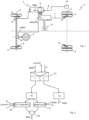
- Fig.1 shows a schematic view of a motor vehicle 1 with a front axle 2 and a rear axle 3, on each of which wheels 4 are arranged.
- the wheels 4 of the front axle 2 can be steered via a steering wheel 5.
- Each wheel 4 is equipped with a wheel brake 6, which can be individually controlled by a driver assistance system 7.
- the driver assistance system 7 is continuously supplied with measured values about dynamic vehicle parameters.
- the driver assistance system 7 takes into account the vehicle speed v, which is determined from measured values of speed sensors 8 of the wheels 4.
- a speed sensor 8 is arranged on each wheel 4, which interacts with a magnet wheel, for example, and generates an electrical signal with information about the speed.
- the driver assistance system 7 determines a slip angle beta of the motor vehicle 1 during cornering, which is used as a measure for assessing driving stability. Depending on its active and/or passive work task, the driver assistance system determines the current slip angle beta is used to determine suitable intervention measures in the driving stability of the motor vehicle 1. For this purpose, the driver assistance system is designed to determine active steering and/or braking interventions taking into account the slip angle beta. The driver assistance system 7 is advantageously designed to detect oversteering or understeering tendencies taking into account the slip angle beta. For other possible work tasks, the driver assistance system 7 is designed to determine trajectories taking into account the slip angle beta, for example lane control.
- the current steering angle delta is specified as an input variable to the driver assistance system 7, which is determined via the turned position of the wheels 5 of the front axle 2.
- the steering angle delta is detected via a steering wheel sensor 10 and made available to the driver assistance system 7.
- the driver assistance system 7 detects a cornering movement variable of the motor vehicle 1 in relation to its center of gravity S.
- the cornering movement variable can be the yaw rate psi Vietnamese or the lateral acceleration a of the motor vehicle 1.
- the driver assistance system 7 is assigned a lateral acceleration sensor 11, the measurement signal of which provides information about cornering movement variables of the motor vehicle 1, in particular the yaw rate psiyak and/or the current lateral acceleration a.
- the driver assistance system 7 also takes into account the position of the center of gravity S between the axles 2, 3 as an input variable for determining the slip angle beta.
- the position of the center of gravity S which depends among other things on the load of the motor vehicle, is measured as required by a detection device 12.
- the measurement results from axle load sensors can be used and the center of gravity position can be determined electronically using appropriate algorithms.
- the determination 9 of the slip angle beta is shown schematically in Fig.2 shown.
- the slip angle beta is determined during stable cornering of the motor vehicle in a manner explained below under simplified assumptions according to the invention.
- a stability query 13 checks and clarifies whether stable cornering is taking place. For this purpose, a temporal change in the input variables is monitored. If either the steering angle delta, the vehicle speed v or the recorded cornering movement variable (yaw rate psi Vietnamese or lateral acceleration a) change in such a way that the range of predetermined stability criteria is left, it is assumed that stable cornering is not taking place.
- the slip angle beta is determined by integrating 14 the difference between the measured yaw rate psiddling and a theoretical value of the yaw rate, which is derived from the lateral acceleration a.
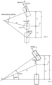
- Fig. 3 shows cornering with the curve radius R around the instantaneous center P, with the front wheel turned at the steering angle delta.
- the curve radius is related to the position of the center of gravity S of the vehicle, which is located at a rear axle distance Lh from the axis of the rear wheel.
- the wheelbase L i.e. the distance between the front axle and the rear axle, is structurally fixed.
- the curve radius R is determined in the single-track model as the quotient of the vehicle speed v and the yaw rate psiyak, which each act on the center of gravity S.
- the slip angle beta is defined by the direction of movement of the vehicle at the center of gravity S and the direction of the vehicle's longitudinal axis when cornering.
- the front wheel is set at exactly the angle at which the imaginary extended front axle and the imaginary extended rear axle intersect at the instantaneous center P.
- This steering angle is called the Ackermann angle deltaA and corresponds to the quotient of wheelbase L and curve radius R.
- the sideslip angle under Ackermann conditions which is called the Ackermann sideslip angle beta0, also has no slip component.
- the determination of the slip angle beta during stationary cornering can also be carried out without recording slip-related variables if the mathematical vehicle model assumes that the difference between the slip angle beta and the Ackermann slip angle beta0 is proportional to the difference between the Ackermann angle deltaA and the steering angle delta.
- This relationship is given in Fig.5 graphically represented and corresponds to the following proportionality: beta ⁇ beta0 ⁇ deltaA ⁇ delta
- the proportionality relationship is used to calculate the theoretical Ackermann sideslip angle beta0 when driving the same curve without slipping to the actual angle determined by the method according to Fig.2
- This assumption relates the differences assumed to be proportional to the respective values under Ackermann conditions, where, as is known, no slip occurs.
- the relationships of the steering angle and the sideslip angle under Ackermann conditions defined in the single-track model apply, i.e. the Ackermann angle and the Ackermann sideslip angle, so that the sideslip angle sought is determined.
- a first quotient 16 is determined from the product of twice the rear axle distance Lh and the yaw rate psipoint in relation to the vehicle speed v.
- a second quotient 17 is formed from the product of the steering angle delta and the rear axle distance Lh in relation to the wheelbase L.
- the difference 18 between the first quotient 16 and the second quotient 17 is the required sideslip angle beta during stationary cornering.
- the lateral acceleration a is determined or measured as the cornering movement variable instead of the yaw rate psiddling.
- the first quotient is determined from the product of twice the rear axle distance Lh and the lateral acceleration a compared to the square of the vehicle speed v.
Landscapes
- Engineering & Computer Science (AREA)
- Transportation (AREA)
- Mechanical Engineering (AREA)
- Automation & Control Theory (AREA)
- Physics & Mathematics (AREA)
- Mathematical Physics (AREA)
- Chemical & Material Sciences (AREA)
- Combustion & Propulsion (AREA)
- Steering Control In Accordance With Driving Conditions (AREA)
- Control Of Driving Devices And Active Controlling Of Vehicle (AREA)
Description
- Die Erfindung betrifft ein Verfahren zur Bestimmung eines Schwimmwinkels während einer Kurvenfahrt eines Kraftwagens gemäß dem Oberbegriff des Anspruchs 1. Die Erfindung betrifft außerdem gemäß Anspruch 7 ein Fahrerassistenzsystem zur Durchführung des Verfahrens sowie gemäß Anspruch 11 einen Kraftwagen mit einem solchen Fahrerassistenzsystem.
- In Kurvenfahrten eines Kraftwagens bewegt sich dessen Schwerpunkt nicht entlang der Fahrzeuglängsachse. Der Winkel zwischen der Bewegungsrichtung des Kraftwagens im Schwerpunkt und der Fahrzeuglängsachse bei der Kurvenfahrt wird Schwimmwinkel genannt. Er setzt sich aus einem geometrischen Anteil, der nur von der Position des Schwerpunkts im Fahrzeug und dem Kurvenradius abhängt, sowie dem Schräglaufwinkel der Hinterachse zusammen.
- Der Schwimmwinkel kann in vielen Fahrsituationen als Maß für die Fahrstabilität des Kraftwagens herangezogen und Fahrerassistenzsystemen bereitgestellt werden, beispielsweise für Fahrdynamikregelungen. Insbesondere für Lastkraftwagen sind viele Fahrerassistenzfunktionen vorgesehen, deren Effizienz durch Kenntnis des aktuellen Schwimmwinkels verbessert ist. Der Schwimmwinkel kann allerdings nur mit sehr großem Aufwand gemessen werden und wird üblicherweise durch Schätzung bestimmt. Oft werden dabei leichter messbare oder bereits bekannte Eingangsgrößen erfasst und über ein mathematisches Fahrzeugmodell verknüpft.
-
DE 10 2006 009 682 A1 offenbart ein Verfahren zum Bestimmen des Fahrzustands eines zweispurigen Fahrzeugs durch Schätzung des Schwimmwinkels über ein mathematisches Modell aufgrund aktuell am Fahrzeug gemessener Werte sowie mittels eines auf diesem Modell basierenden Beobachteransatzes. Bei dem bekannten Verfahren werden als am Fahrzeug gemessene Werte die Reifenkräfte oder Radkräfte zumindest in Fahrzeug-Querrichtung verwendet sowie ferner zumindest ein Lenkwinkel für die beiden Räder der Vorderachse. Außerdem wird eine Information über die Lage des Schwerpunkts des Fahrzeugs zwischen einer Vorderachse und einer Hinterachse berücksichtigt, Weiterhin werden zum Abgleich des Beobachteransatzes die gemessene Gierrate oder Gierbeschleunigung sowie die Längsgeschwindigkeit des Fahrzeugs herangezogen. - Die Reifenseitenkräfte, deren Kenntnis das bekannte Verfahren benötigt, sind jedoch im Betrieb des Fahrzeugs nicht oder nur äußerst aufwändig zu messen.
-
DE 10 2010 050 278 A1 offenbart ein Verfahren zum Schätzen eines Schwimmwinkels, bei dem Informationen zu Eingangsgrößen über die Annahmen des linearen Einspurmodells verknüpft werden, dessen Zustandsgröße schließlich der Schwimmwinkel ist. Als Eingangsgrößen werden der Lenkwinkel und die Geschwindigkeit des Fahrzeugs gemessen. Wenigstens eine weitere Größe, nämlich die Gierbeschleunigung und/oder die Querbeschleunigung werden anhand des mathematischen Modells auf Grundlage der Messwerte berechnet. Dabei werden bei der Anwendung des Einspurmodells auch Größen berücksichtigt, welche durch die Lage des Schwerpunkts des Kraftfahrzeugs zwischen einer Vorderachse und einer Hinterachse bestimmt sind. Für die Schätzung des Schwimmwinkels auf der Grundlage des Einspurmodells benötigt das bekannte Verfahren einen neuen Wert eines nicht gemessenen Parameters, nämlich die Schräglaufsteifigkeit an zumindest einem Rad. Die Bestimmung der Schräglaufsteifigkeit realisiert das bekannte Verfahren über einen Beobachteransatz unter Verwendung eines Kalman-Filters. Der Schwimmwinkel wird schließlich mit Hilfe des linearen Einspurmodells bestimmt, und zwar unter Zuhilfenahme der jeweils aktuellen Werte für die Schräglaufsteifigkeiten. -
EP 0 970 876 A2 zeigt ein Radschlupfwinkelerfassungssystem für ein Kraftfahrzeug. Ein Fahrzustand eines Fahrzeugs wird hier durch eine Fahrzustandserfassungsvorrichtung erfasst. Ein Querschlupfwinkel einer Fahrzeugkarosserie wird als erster Querschlupfwinkel in einer ersten Querschlupfwinkel-Berechnungsvorrichtung berechnet, indem ein differenzierter Wert des Querschlupfwinkels integriert wird, der auf der Grundlage eines nichtlinearen Vierradfahrzeugs bestimmt wird Bewegungsmodell. Ein Querschlupfwinkel der Fahrzeugkarosserie wird als ein zweiter Querschlupfwinkel in einer zweiten Querschlupfwinkel-Berechnungsvorrichtung durch eine Berechnung in einem linearen Bewegungsmodell eines Zweiradfahrzeugs berechnet. Einer der ersten und zweiten Seitenschlupfwinkel wird alternativ in einer Auswahlvorrichtung in Übereinstimmung mit dem Fahrzustand ausgewählt, der durch die Fahrzustandserfassungsvorrichtung erfasst wird, so dass der zweite Seitenschlupfwinkel ausgewählt wird, wenn der Fahrzustand vorliegt, die Erfassungsvorrichtung einen Zustand erfasst, in dem das Fahrzeug mit niedriger Geschwindigkeit geradeaus fährt. Ein Schlupfwinkel jedes der Räder wird durch eine Schlupfwinkel-Berechnungsvorrichtung basierend auf dem Querschlupfwinkel in der Auswahlvorrichtung berechnet. - Aufgabe der Erfindung ist es demgemäß, die Bestimmung des Schwimmwinkels während der Kurvenfahrt eines Kraftwagens, insbesondere eines Lastkraftwagens, zu vereinfachen.
- Die Aufgabe wird erfindungsgemäß durch ein Verfahren zur Bestimmung eines Schwimmwinkels während der Kurvenfahrt eines Kraftwagens mit den Merkmalen des Anspruchs 1 gelöst. Die Aufgabe wird außerdem durch ein Fahrerassistenzsystem zur Durchführung des Verfahrens mit den Merkmalen des Anspruchs 6 sowie gemäß Anspruch 10 durch einen Kraftwagen mit einem solchen Fahrerassistenzsystem gelöst.
- Gemäß der Erfindung wird der Schwimmwinkel im Fall einer stabilen Kurvenfahrt des Kraftwagens unter der Annahme bestimmt, dass die Differenz zwischen dem Schwimmwinkel und dem Schwimmwinkel unter Ackermann- Bedingungen, dem sogenannten Ackermannschwimmwinkel, proportional zu der Differenz zwischen dem Ackermannwinkel und dem Lenkwinkel ist. Als stabile Kurvenfahrt wird eine Kurvenfahrt verstanden, bei der die ermittelten Fahrdynamikgrößen innerhalb eines Bereichs vorgegebener Stabilitätskriterien liegen, deren Überschreiten einen Eingriff in die Fahrstabilität indizieren kann. Eine stabile Kurvenfahrt kann beispielsweise eine stationäre Kreisfahrt oder eine konstante Kreisfahrt sein, wobei Änderungen der Werte des Lenkwinkels und/oder der Längsgeschwindigkeit und/oder der Querbeschleunigung unter Berücksichtigung des Kurvenradius unter Berücksichtigung der vorgegebenen Stabilitätskriterien einem dynamisch stabilen Fahrzustand genügen und quasistationär behandelt werden können. Die erfindungsgemäße Annahme entspricht der folgenden Gleichung:

mit beta Schwimmwinkel beta0 Ackermannschwimmwinkel delta Lenkwinkel deltaA Ackermannwinkel - Der Ackermannwinkel ist dabei der Winkel, der von den Polstrahlen vom Momentanpol der Kurvenfahrt zur Vorderachse und zur Hinterachse eingeschlossen wird. Unter dem Ackermannschwimmwinkel wird derjenige Schwimmwinkel verstanden, der sich theoretisch bei schlupffreier Fahrt der gleichen Kurve einstellt. Aus der Beziehung des gemessenen Lenkwinkels und des Ackermannwinkels über die Proportionalitätsbeziehung vom Ackermannschwimmwinkel wird auf den tatsächlichen Schwimmwinkel geschlossen. Unter Berücksichtigung der linearen Proportionalität ergibt sich folgende Beziehung der Differenz des Schwimmwinkels und des Ackermannschwimmwinkel gegenüber dem Ackermannschwimmwinkel sowie der Differenz des Ackermannwinkels und des Lenkwinkels gegenüber dem Ackermannwinkel, aus der die gesuchte Information über den Schwimmwinkel hergeleitet wird:

- Das mathematische Modell, welches das Fahrerassistenzsystem der Bestimmung des Schwimmwinkels zugrunde legt, umfasst gemäß der Erfindung die vorstehende Annahme gemäß Gleichung 2.
- Die Erfindung hat dabei erkannt, dass sowohl der Ackermannwinkel als auch der Ackermannschwimmwinkel theoretisch schlupffreie Fahrsituationen sind und mit Kenntnis des Radstands und der Schwerpunktlage allein mit dem gemessenen Lenkwinkel und der aktuellen Kurvenfahrtbewegungsgröße des Kraftwagens bestimmt werden können.
- Die Erfindung zeigt damit einen Weg auf, den Schwimmwinkel bei stabiler Kurvenfahrt des Kraftwagens den Schwimmwinkel mit hinreichender Präzision allein auf der Grundlage der aktuell gemessenen Eingangsgrößen zu bestimmen, das heißt der Fahrzeuggeschwindigkeit des Kraftwagens, des Lenkwinkels sowie einer Kurvenfahrtbewegungsgröße des Kraftwagens.
- Der tatsächliche Lenkwinkel wird beispielsweise durch einen Lenkwinkelsensor an der Lenksäule ermittelt. Als Kurvenfahrtbewegungsgröße wird bevorzugt diejenige Größe herangezogen, welche dem Fahrerassistenzsystem bereits für andere Funktionen bereitgestellt ist. Dabei kann beispielsweise die Querbeschleunigung als geeignete Kurvenfahrtbewegungsgröße durch einen ESC-Sensor ermittelt werden. Die Information zur Fahrzeuggeschwindigkeit des Kraftwagens wird über Messwerte von Drehzahlsensoren, etwa Polradsensoren, an den Rädern bereitgestellt.
- Insbesondere ist bei dem erfindungsgemäßen Ansatz keine Ermittlung der Schräglaufsteifigkeiten erforderlich. Dem liegt die praktische Annahme zugrunde, dass der theoretisch betrachtete Fahrzustand nicht vollständig schlupffrei ist, sondern nur sehr nahe an den Ackermann-Bedingungen liegen soll. Damit wird für die erfindungsgemäße Bestimmung des Schwimmwinkels unterstellt, dass die Gleichungen des linearen Einspurmodells ihre Gültigkeit haben, wodurch auch in diesem theoretischen Fahrzustand das Verhältnis der Schräglaufsteifigkeiten der Vorder- und Hinterachse einen Einfluss auf Lenk- und Schwimmwinkel haben. Da diese aber sehr nahe an Lenk- und Schwimmwinkel bei völlig schlupffreier Fahrt liegen, vernachlässigt der erfindungsgemäße Ansatz diese Abweichung bewusst.
- Insbesondere bedarf es bei der erfindungsgemäßen Bestimmung des Schwimmwinkels während einer stabilen Kurvenfahrt keiner gesonderten Berücksichtigung des Einflusses der Schräglaufsteifigkeiten. Durch Kenntnis des jeweiligen Radstands und der Schwerpunktlage in Fahrzeuglängsrichtung können so der Lenkwinkel und der Schwimmwinkel aus den kinematischen Beziehungen bei Ackermann-Bedingungen berechnet werden, die theoretisch zum Befahren der vorliegenden Kurve bei unendlich langsamer (und damit schlupffreier) Fahrt erforderlich wären. Die Erfindung hat nämlich erkannt, dass das Verhältnis der Schräglaufsteifigkeiten konstant über den betrachteten Bereich ist und daher den gleichen Einfluss auf Zähler und Nenner in der Proportionalitätsbeziehung hat, so dass die Kenntnis des genauen Schräglaufsteifigkeitsverhältnisses nicht erforderlich ist. Anders ausgedrückt sind Lenkwinkel und Schwimmwinkel unter Ackermann-Bedingungen gewissermaßen der Nullpunkt der Betrachtung der Kurvenfahrt, von dem sich der Kraftwagen mit zunehmender Geschwindigkeit immer weiter entfernt. Durch die Annahme der Linearität der Reifeneigenschaften im Gültigkeitsbereich des linearen Einspurmodells kann in diesem Bereich immer ausgehend von diesem Nullpunkt vom tatsächlich vorliegenden Lenkwinkel auf den tatsächlich vorliegenden Schwimmwinkel geschlossen werden.
- Die Bestimmung der Lage des Schwerpunkts zwischen den Achsen erfolgt in einer elektronischen Ausführungsform der Erfindung über eine elektronische Auswertung von Messwerten, beispielsweise von Achslastsensoren. Die Information über den Radstand des Kraftwagens liegt konstruktiv fest und steht für die Schwerpunktbestimmung zur Verfügung.
- Der gesuchte Schwimmwinkel lässt sich in einer einfach zu verarbeitenden Beziehung als Differenz eines ersten Quotienten aus zweifacher Hinterachsentfernung des Schwerpunkts von der Hinterachse gegenüber dem Kurvenradius, sowie eines zweiten Quotienten des Produkts von Lenkwinkel und Hinterachsentfernung gegenüber dem Radstand zwischen der Vorderachse und der Hinterachse bestimmt werden.
- Da der Kurvenradius im linearen Einspurmodell als Verhältnis der Fahrzeuggeschwindigkeit zur Kurvenfahrtbewegungsgröße bestimmt ist, lässt sich in einer vorteilhaften Ausführungsform der Erfindung, bei der als Kurvenfahrtbewegungsgröße die Giergeschwindigkeit ermittelt oder gemessen wird, folgende Gleichung angeben:

mit Lh Hinterachsentfernung L Radstand psipunkt Giergeschwindigkeit v Fahrzeuggeschwindigkeit - Wird alternativ zur Giergeschwindigkeit als Kurvenfahrtbewegungsgröße eine Querbeschleunigung a ermittelt oder gemessen, so ergibt sich folgende Gleichung zur Bestimmung des gesuchten Schwimmwinkels:

mit a Querbeschleunigung - Das Fahrerassistenzsystem ist in einer vorteilhaften Ausführungsform der Erfindung zur Bestimmung von aktiven Lenkeingriffen unter Berücksichtigung des Schwimmwinkels ausgebildet. Dabei können durch den erfindungsgemäßen Ansatz zur Bestimmung des Schwimmwinkels bei stationärer Kurvenfahrt sehr schnell und präzise Informationen über die Fahrstabilität bereitgestellt und entsprechende Eingriffe berechnet werden.
- In einer weiteren bevorzugten Ausführungsform ist das Fahrerassistenzsystem zur Bestimmung von Trajektorien unter Berücksichtigung des Schwimmwinkels ausgebildet.
- Die laufend aktualisierbaren Informationen zum Schwimmwinkel lassen genaue Rückschlüsse auf Über- oder Untersteuertendenzen des Kraftwagens zu. Vor diesem Hintergrund ist das erfindungsgemäße Fahrerassistenzsystem zur Detektion von Über- oder Untersteuertendenzen unter Berücksichtigung des Schwimmwinkels ausgebildet.
- Wenn keine stabile Kurvenfahrt gegeben ist, wird der Schwimmwinkel nach einem an sich bekannten Verfahren mit Beobachtersystem oder Integration bestimmt. Vorzugsweise wird dann der Schwimmwinkel bestimmt durch Integration der Differenz zwischen gemessener Giergeschwindigkeit und einem Wert der Giergeschwindigkeit, welcher aus der Querbeschleunigung hergeleitet wird. Ausführungsbeispiele der Erfindung sind nachstehend anhand der Zeichnung näher erläutert. Es zeigen:
-
Fig. 1 einen schematisch dargestellten Kraftwagen mit einem Ausführungsbeispiel eines Fahrerassistenzsystem gemäß der Erfindung, -
Fig. 2 ein Flussschaubild eines Ausführungsbeispiels eines Verfahrens zur Bestimmung eines Schwimmwinkels während der Kurvenfahrt des Kraftwagens; -
Fig. 3 eine Darstellung der geometrischen Beziehungen am Kraftwagen gemäß dem Einspurmodell; -
Fig. 4 eine Darstellung der geometrischen Beziehungen unter Ackermann-Bedingungen gemäß dem Einspurmodell; -
Fig.5 eine grafische Darstellung der Beziehung des Lenkwinkels gegenüber dem Schwimmwinkel bei stationärer Kurvenfahrt. -
Fig. 1 zeigt eine schematische Ansicht eines Kraftwagens 1 mit einer Vorderachse 2 und einer Hinterachse 3, an denen jeweils Räder 4 angeordnet sind. Die Räder 4 der Vorderachse 2 sind lenkbar über ein Lenkrad 5. Jedes Rad 4 ist mit einer Radbremse 6 ausgestattet, welche von einem Fahrerassistenzsystem 7 individuell ansteuerbar ist. Dem Fahrerassistenzsystem 7 werden laufend Messwerte über dynamische Fahrzeugparameter zugeführt. Berücksichtigt wird vom Fahrerassistenzsystem 7 die Fahrzeuggeschwindigkeit v, welche aus Messwerten von Drehzahlsensoren 8 der Räder 4 ermittelt wird. Im gezeigten Ausführungsbeispiel ist an jedem Rad 4 jeweils ein Drehzahlsensor 8 angeordnet, welcher beispielsweise mit einem Polrad zusammenwirkt und ein elektrisches Signal mit Aussage über die Drehzahl erzeugt. - Das Fahrerassistenzsystem 7 bestimmt einen Schwimmwinkel beta des Kraftwagens 1 während der Kurvenfahrt, welcher als Maß für die Beurteilung der Fahrstabilität herangezogen wird. Entsprechend seiner aktiven und/oder passiven Arbeitsaufgabe legt das Fahrerassistenzsystem den aktuellen Schwimmwinkel beta der Bestimmung geeigneter Eingriffsmaßnahmen in die Fahrstabilität des Kraftwagens 1 zugrunde. Hierzu ist das Fahrerassistenzsystem zur Bestimmung von aktiven Lenk- und/oder Bremseingriffen unter Berücksichtigung des Schwimmwinkels beta ausgebildet. Vorteilhaft ist das Fahrerassistenzsystem 7 zur Detektion von Über- oder Untersteuertendenzen unter Berücksichtigung des Schwimmwinkels beta ausgebildet. Bei weiteren möglichen Arbeitsaufgaben ist das Fahrerassistenzsystem 7 zur Bestimmung von Trajektorien unter Berücksichtigung des Schwimmwinkels beta ausgebildet, beispielsweise Spurkontrolle.
- Dem Fahrerassistenzsystem 7 wird zur Bestimmung 9 des aktuellen Schwimmwinkels beta als Eingangsgröße der aktuelle Lenkwinkel delta vorgegeben, welcher über die eingeschlagene Stellung der Räder 5 der Vorderachse 2 bestimmt ist. Der Lenkwinkel delta wird im gezeigten Ausführungsbeispiel über einen Lenkradsensor 10 erfasst und dem Fahrerassistenzsystem 7 zur Verfügung gestellt. Als weitere Eingangsgröße erfasst das Fahrerassistenzsystem 7 eine Kurvenfahrtbewegungsgröße des Kraftwagens 1 in Bezug auf dessen Schwerpunkt S. Die Kurvenfahrtbewegungsgröße kann die Giergeschwindigkeit psipunkt oder die Querbeschleunigung a des Kraftwagens 1 sein. Dem Fahrerassistenzsystem 7 ist ein Querbeschleunigungssensor 11 zugeordnet, dessen Messsignal Aussagen über Kurvenfahrtbewegungsgrößen des Kraftwagens 1 bereitstellt, insbesondere die Giergeschwindigkeit psipunkt und/oder die aktuelle Querbeschleunigung a.
- Das Fahrerassistenzsystem 7 berücksichtigt als Eingangsgröße für die Bestimmung des Schwimmwinkels beta auch die Lage des Schwerpunkts S zwischen den Achsen 2, 3. Die Lage des Schwerpunkts S, welche unter anderem von der Beladung des Kraftwagens abhängig ist, wird durch eine Erfassungseinrichtung 12 bedarfsweise gemessen. Hierzu können beispielsweise die Messergebnisse von Achslastsensoren herangezogen werden und die Schwerpunktlage unter Anwendung entsprechender Algorithmen elektronisch bestimmt werden.
- Die Bestimmung 9 des Schwimmwinkels beta ist schematisch in
Fig.2 dargestellt. - Der Schwimmwinkel beta wird während stabiler Kurvenfahrten des Kraftwagens in einer nachstehend erläuterten Weise unter vereinfachenden Annahmen gemäß der Erfindung ermittelt. Dabei wird in einem ersten Schritt in einer Stabilitätsabfrage 13 geprüft und geklärt, ob eine stabile Kurvenfahrt vorliegt. Hierzu wird eine zeitliche Veränderung der Eingangsgrößen überwacht. Verändern sich entweder der Lenkwinkel delta, die Fahrzeuggeschwindigkeit v oder die erfasste Kurvenfahrtbewegungsgröße (Giergeschwindigkeit psipunkt oder Querbeschleunigung a) derart, dass der Bereich vorgegebener Stabilitätskriterien verlassen wird, so wird davon ausgegangen, dass keine stabile Kurvenfahrt gegeben ist. In diesem Fall wird der Schwimmwinkel beta durch Integration 14 der Differenz zwischen gemessener Giergeschwindigkeit psipunkt und einem theoretischen Wert der Giergeschwindigkeit bestimmt, welcher aus der Querbeschleunigung a hergeleitet wird.
- Bei stabilen Kurvenfahrten werden die erfassten Eingangsgrößen über ein mathematisches Fahrzeugmodell 15 mit den Annahmen des linearen Einspurmodells miteinander verknüpft. Die im Einspurmodell geltenden Winkelbeziehungen sind in
Fig. 3 und Fig. 4 dargestellt.Fig. 3 zeigt eine Kurvenfahrt mit dem Kurvenradius R um den Momentanpol P, wobei das Vorderrad mit dem Lenkwinkel delta eingeschlagen ist. Der Kurvenradius ist dabei bezogen auf die Lage des Schwerpunkts S des Kraftwagens, welcher mit einer Hinterachsentfernung Lh von der Achse des Hinterrades entfernt liegt. Der Radstand L, das heißt der Abstand zwischen Vorderachse und Hinterachse, liegt konstruktiv fest. Der Kurvenradius R ist im Einspurmodell bestimmt als Quotient aus Fahrzeuggeschwindigkeit v und Giergeschwindigkeit psipunkt, welche jeweils am Schwerpunkt S wirken. Durch die Bewegungsrichtung des Kraftwagens im Schwerpunkt S und die Richtung der Fahrzeuglängsachse bei der Kurvenfahrt ist der Schwimmwinkel beta definiert. - Da während realer Fahrt stets Schlupf an den Rädern auftritt, bewegen sich die Räder jeweils mit Schräglaufwinkeln alphav, alphah. Die Schräglaufwinkel stehen in Wechselbeziehung mit dem letztlich zu bestimmenden Schwimmwinkel beta. Der Schräglaufwinkel alphah des Hinterrades ist nach dem Einspurmodell die Differenz zwischen dem Quotienten aus Hinterachsentfernung und Kurvenradius und dem Schwimmwinkel beta, gemäß folgender Gleichung:

- Schlupf tritt allerdings nicht unter den sogenannten Ackermann-Bedingungen auf. In dieser Situation, die
Fig. 4 darstellt, ist das Vorderrad mit genau demjenigen Winkel angestellt, in der sich die gedanklich verlängerte Vorderachse und die gedanklich verlängerte Hinterachse im Momentanpol P schneiden. Dieser Lenkwinkel wird als Ackermannwinkel deltaA bezeichnet und entspricht dem Quotienten aus Radstand L und Kurvenradius R. Ebenfalls ohne Schlupfanteil ist der Schwimmwinkel unter Ackermannbedingungen, welcher als Ackermannschwimmwinkel beta0 bezeichnet wird. - Gemäß der Erfindung kann die Bestimmung des Schwimmwinkels beta während stationärer Kurvenfahrten auch ohne Erfassung von schlupfbezogenen Größen erfolgen, wenn das mathematische Fahrzeugmodell annimmt, dass die Differenz zwischen dem Schwimmwinkel beta und dem Ackermannschwimmwinkel beta0 proportional zu der Differenz zwischen dem Ackermannwinkel deltaA und dem Lenkwinkel delta ist. Diese Beziehung ist in
Fig. 5 grafisch dargestellt und entspricht der folgenden Proportionalität:
- Aus der Beziehung des gemessenen Lenkwinkels delta und des Ackermannwinkels deltaA wird über die Proportionalitätsbeziehung vom theoretisch bei schlupffreier Fahrt der gleichen Kurve vorliegenden Ackermannschwimmwinkel beta0 auf den tatsächlichen und vom Verfahren gemäß
Fig. 2 gesuchten Schwimmwinkel beta geschlossen. Dabei macht sich die Erfindung den inFig. 5 dargestellten Zusammenhang nach Grundsätzen des Strahlensatzes zunutze und nimmt an, dass die Differenz zwischen dem Schwimmwinkel beta und dem Ackermannschwimmwinkel beta0 bezogen auf den Ackermannschwimmwinkel gleich ist der Differenz zwischen dem Ackermannwinkel deltaA und dem Lenkwinkel delta bezogen auf den Ackermannwinkel deltaA. Das ergibt folgende Gleichung:
- Diese Annahme bezieht die als proportional angenommenen Differenzen auf die jeweiligen Werte unter Ackermannbedingungen, wobei bekanntlich kein Schlupf auftritt. Dabei gelten die im Einspurmodell definierten Beziehungen des Lenkwinkels und des Schwimmwinkels unter Ackermannbedingungen, das heißt des Ackermannwinkels und des Ackermannschwimmwinkels, so dass der gesuchte Schwimmwinkel bestimmt ist.
- Für das Ausführungsbeispiel gemäß
Fig. 2 mit Erfassung der Giergeschwindigkeit psipunkt ergibt sich die folgende Bestimmungsgleichung für den Schwimmwinkel:
- Es wird somit im Ausführungsbeispiel gemäß
Fig. 2 ein erster Quotient 16 bestimmt aus dem Produkt zweifacher Hinterachsentfernung Lh und der Giergeschwindigkeit psipunkt gegenüber der Fahrzeuggeschwindigkeit v. Ein zweiter Quotient 17 wird gebildet aus dem Produkt von Lenkwinkel delta und Hinterachsentfernung Lh gegenüber dem Radstand L. Die Differenz 18 zwischen dem ersten Quotient 16 und dem zweiten Quotient 17 ist der gesuchte Schwimmwinkel beta während stationärer Kurvenfahrt. - In einem zweiten Ausführungsbeispiel wird als Kurvenfahrtbewegungsgröße anstelle der Giergeschwindigkeit psipunkt die Querbeschleunigung a ermittelt oder gemessen. Dabei wird der erste Quotient aus dem Produkt zweifacher Hinterachsentfernung Lh und der Querbeschleunigung a gegenüber dem Quadrat der Fahrzeuggeschwindigkeit v bestimmt. Der Schwimmwinkel beta ergibt sich dann nach der folgenden Gleichung:

-
- 1
- Kraftwagen
- 2
- Vorderachse
- 3
- Hinterachse
- 4
- Rad
- 5
- Lenkrad
- 6
- Radbremse
- 7
- Fahrerassistenzsystem
- 8
- Drehzahlsensor
- 9
- Bestimmung
- 10
- Lenkradsensor
- 11
- Querbeschleunigungssensor
- 12
- Erfassungseinrichtung
- 13
- Stabilitätsabfrage
- 14
- Integration
- 15
- Mathematisches Fahrzeugmodell
- 16
- Erster Quotient
- 17
- Zweiter Quotient
- 18
- Differenz
- a
- Querbeschleunigung
- alpha
- Schräglaufwinkel
- alphah
- Schräglaufwinkel des Hinterrades
- alphav
- Schräglaufwinkel des Vorderrades
- beta
- Schwimmwinkel
- beta0
- Ackermannschwimmwinkel
- delta
- Lenkwinkel
- deltaA
- Ackermannwinkel
- L
- Radstand
- Lh
- Hinterachsabstand
- psipunkt
- Giergeschwindigkeit
- R
- Kurvenradius
- S
- Schwerpunkt
- v
- Fahrzeuggeschwindigkeit
Claims (10)
- Verfahren zur Bestimmung eines Schwimmwinkels (beta) während der Kurvenfahrt eines Kraftwagens, wobei folgende Eingangsgrößen erfasst und über ein mathematisches Fahrzeugmodell (15) mit den Annahmen des linearen Einspurmodells miteinander verknüpft werden:- eine vorgegebene oder gemessene Lage des Schwerpunkts (S) des Kraftwagens (1) zwischen einer Vorderachse (2) und einer Hinterachse (3) des Kraftwagens (1),- die aktuelle Fahrzeuggeschwindigkeit (v) des Kraftwagens (1),- eine aktuelle Kurvenfahrtbewegungsgröße (psipunkt, a) des Kraftwagens,- der aktuelle Lenkwinkel (delta) an der Vorderachse,dadurch gekennzeichnet, dass im Fall einer stabilen Kurvenfahrt des Kraftwagens (1) der Schwimmwinkel (beta) unter der Annahme bestimmt wird, dass die Differenz zwischen dem Schwimmwinkel (beta) und dem Ackermannschwimmwinkel beta0 proportional zu der Differenz zwischen dem Ackermannwinkel (deltaA) und dem Lenkwinkel (delta) ist, wobei aus der Beziehung des gemessenen Lenkwinkels (delta) und des Ackermannwinkels (deltaA) über die Proportionalitätsbeziehung vom theoretisch bei schlupffreier Fahrt der gleichen Kurve vorliegenden Ackermannschwimmwinkel (beta0) auf den tatsächlichen Schwimmwinkel (beta) geschlossen wird, undder Schwimmwinkel (beta) als Differenz (18) eines ersten Quotienten (16) aus zweifacher Hinterachsentfernung (Lh) des Schwerpunkts (S) von der Hinterachse gegenüber dem Kurvenradius (R), welcher als Verhältnis der Fahrzeuggeschwindigkeit (v) zur Kurvenfahrtbewegungsgröße (psipunkt, a) berücksichtigt wird, sowie eines zweiten Quotienten (17) des Produkts von Lenkwinkel (delta) und Hinterachsentfernung (Lh) gegenüber dem Radstand (L) zwischen der Vorderachse (2) und der Hinterachse (3) bestimmt wird.
- Verfahren nach Anspruch 1,
dadurch gekennzeichnet, dass als Kurvenfahrtbewegungsgröße die Giergeschwindigkeit (psipunkt) ermittelt oder gemessen wird. - Verfahren nach Anspruch 2,
dadurch gekennzeichnet, dass der erste Quotient (16) aus dem Produkt zweifacher Hinterachsentfernung (Lh) und der Giergeschwindigkeit (psipunkt) gegenüber der Fahrzeuggeschwindigkeit (v) bestimmt wird. - Verfahren nach Anspruch 1,
dadurch gekennzeichnet, dass als Kurvenfahrtbewegungsgröße die Querbeschleunigung (a) ermittelt oder gemessen wird. - Verfahren nach einem der vorhergehenden Ansprüche,
dadurch gekennzeichnet, dass in Fällen, dass keine stabile Kurvenfahrt gegeben ist, der Schwimmwinkel (beta) bestimmt wird durch Integration (14) der Differenz zwischen gemessener Giergeschwindigkeit (psipunkt) und einem Wert der Giergeschwindigkeit, welcher aus der Querbeschleunigung (a) hergeleitet wird. - Fahrerassistenzsystem für Kraftwagen, welches zur Durchführung des Verfahrens zur Bestimmung eines Schwimmwinkels (beta) nach einem der vorhergehenden Ansprüche ausgebildet ist, wobei dem Fahrerassistenzsystem ein mathematisches Modell mit den Annahmen des linearen Einspurmodells zur Verknüpfung folgender Eingangsgrößen vorgegeben ist:- eine vorgegebene oder gemessene Lage des Schwerpunkts (S) des Kraftwagens zwischen einer Vorderachse und einer Hinterachse des Kraftwagens,- die aktuelle Fahrzeuggeschwindigkeit (v) des Kraftwagens (1),- eine aktuelle Kurvenfahrtbewegungsgröße (psipunkt, a) des Kraftwagens (1),- der aktuelle Lenkwinkel (delta) an der Vorderachse,dadurch gekennzeichnet, dass das mathematische Fahrzeugmodell für die Bestimmung des Schwimmwinkels (beta) bei stabilen Kurvenfahrten des Kraftwagens die Annahme umfasst, dass die Differenz zwischen dem Schwimmwinkel (beta) und dem Ackermannschwimmwinkel (beta0) proportional zu der Differenz zwischen dem Ackermannwinkel (deltaA) und dem Lenkwinkel (delta) ist, wobei das Fahrerassistenzsystem dazu ausgebildet ist, aus der Beziehung des gemessenen Lenkwinkels (delta) und des Ackermannwinkels (deltaA) über die Proportionalitätsbeziehung vom theoretisch bei schlupffreier Fahrt der gleichen Kurve vorliegenden Ackermannschwimmwinkel (beta0) auf den tatsächlichen Schwimmwinkel (beta) zu schließen;wobei der Schwimmwinkel (beta) als Differenz (18) eines ersten Quotienten (16) aus zweifacher Hinterachsentfernung (Lh) des Schwerpunkts (S) von der Hinterachse gegenüber dem Kurvenradius (R), welcher als Verhältnis der Fahrzeuggeschwindigkeit (v) zur Kurvenfahrtbewegungsgröße (psipunkt, a) berücksichtigt wird, sowie eines zweiten Quotienten (17) des Produkts von Lenkwinkel (delta) und Hinterachsentfernung (Lh) gegenüber dem Radstand (L) zwischen der Vorderachse (2) und der Hinterachse (3) bestimmbar ist.
- Fahrerassistenzsystem nach Anspruch 6,
dadurch gekennzeichnet, dass das Fahrerassistenzsystem zur Bestimmung von aktiven Lenk- und/oder Bremseingriffen unter Berücksichtigung des Schwimmwinkels (beta) ausgebildet ist. - Fahrerassistenzsystem nach Anspruch 6 oder 7,
dadurch gekennzeichnet, dass das Fahrerassistenzsystem zur Bestimmung von Trajektorien unter Berücksichtigung des Schwimmwinkels (beta) ausgebildet ist. - Fahrerassistenzsystem nach Anspruch 6, 7 oder 8,
dadurch gekennzeichnet, dass das Fahrerassistenzsystem zur Detektion von Über- oder Untersteuertendenzen unter Berücksichtigung des Schwimmwinkels (beta) ausgebildet ist. - Kraftwagen mit einem Fahrerassistenzsystem gemäß einem der Ansprüche 6 bis 9.
Applications Claiming Priority (2)
| Application Number | Priority Date | Filing Date | Title |
|---|---|---|---|
| DE102019112900.1A DE102019112900A1 (de) | 2019-05-16 | 2019-05-16 | Verfahren zur Bestimmung eines Schwimmwinkels während einer Kurvenfahrt eines Kraftwagens, Fahrerassistenzsystem zur Durchführung des Verfahrens sowie Kraftwagen |
| PCT/EP2020/063399 WO2020229573A1 (de) | 2019-05-16 | 2020-05-14 | Verfahren zur bestimmung eines schwimmwinkels während einer kurvenfahrt eines kraftwagens, fahrerassistenzsystem zur durchführung des verfahrens sowie kraftwagen |
Publications (2)
| Publication Number | Publication Date |
|---|---|
| EP3969336A1 EP3969336A1 (de) | 2022-03-23 |
| EP3969336B1 true EP3969336B1 (de) | 2024-06-12 |
Family
ID=70918393
Family Applications (1)
| Application Number | Title | Priority Date | Filing Date |
|---|---|---|---|
| EP20728974.5A Active EP3969336B1 (de) | 2019-05-16 | 2020-05-14 | Verfahren zur bestimmung eines schwimmwinkels während einer kurvenfahrt eines kraftwagens, fahrerassistenzsystem zur durchführung des verfahrens sowie kraftwagen |
Country Status (5)
| Country | Link |
|---|---|
| US (1) | US11814051B2 (de) |
| EP (1) | EP3969336B1 (de) |
| CN (1) | CN113825683B (de) |
| DE (1) | DE102019112900A1 (de) |
| WO (1) | WO2020229573A1 (de) |
Families Citing this family (4)
| Publication number | Priority date | Publication date | Assignee | Title |
|---|---|---|---|---|
| DE102020208391B4 (de) * | 2020-07-03 | 2024-08-14 | Continental Autonomous Mobility Germany GmbH | Verfahren zur teil- oder vollautonomen Führung eines Kraftfahrzeugs |
| DE102021204026A1 (de) | 2021-04-22 | 2022-10-27 | Continental Automotive Technologies GmbH | Verfahren zur Bestimmung von Fahrdynamikgrößen eines Kraftfahrzeugs |
| CN114212078B (zh) * | 2022-01-18 | 2023-10-10 | 武汉光庭信息技术股份有限公司 | 一种自动泊车中自车定位精度检测方法和系统 |
| US12252200B2 (en) * | 2022-09-30 | 2025-03-18 | Zoox, Inc. | Determining vehicle position using sideslip vector |
Family Cites Families (13)
| Publication number | Priority date | Publication date | Assignee | Title |
|---|---|---|---|---|
| JP3669668B2 (ja) | 1998-07-10 | 2005-07-13 | 本田技研工業株式会社 | 車両用車輪スリップ角検出装置 |
| CN100408398C (zh) * | 2003-10-28 | 2008-08-06 | 大陆-特韦斯贸易合伙股份公司及两合公司 | 用于改善车辆的行驶性能的方法及系统 |
| DE102005004894A1 (de) * | 2005-02-03 | 2006-08-17 | Robert Bosch Gmbh | Auslöseverfahren zur Aktivierung einer Lateralgeschwindigkeitsschätzung für Insassenschutzvorrichtungen |
| JP5011866B2 (ja) * | 2006-01-23 | 2012-08-29 | 日産自動車株式会社 | 横すべり角推定装置、自動車、及び横すべり角推定方法 |
| DE102006009682A1 (de) * | 2006-03-02 | 2007-09-06 | Bayerische Motoren Werke Ag | Verfahren zum Bestimmen des Fahrzustands eines zweispurigen Fahrzeugs durch Schwimmwinkel-Schätzung |
| DE102010050278A1 (de) * | 2010-11-02 | 2012-05-03 | Audi Ag | Verfahren zum Schätzen eines Schwimmwinkels |
| DE102013224305A1 (de) * | 2013-11-27 | 2015-05-28 | Robert Bosch Gmbh | Verfahren zur Schwimmwinkelbestimmung in einem Fahrzeug |
| DE102014220865B4 (de) * | 2014-10-15 | 2019-07-18 | Bayerische Motoren Werke Aktiengesellschaft | Stationär genaue und kooperative Trajektorienfolgeregelung |
| DE102015010173B3 (de) * | 2015-08-06 | 2016-07-14 | Audi Ag | Verfahren zur Schwimmwinkelmessung in Fahrzeugen |
| KR102122671B1 (ko) * | 2015-09-14 | 2020-06-12 | 콘티넨탈 테베스 아게 운트 코. 오하게 | 전자식 브레이크 제어 유닛 및 자동차의 폐쇄 루프 제어를 수행하기 위한 방법 |
| FR3044994B1 (fr) * | 2015-12-15 | 2022-09-02 | Renault Sas | Procede de determination d'un vecteur de coefficients permettant de determiner un angle de braquage a appliquer a des roues d'un vehicule automobile |
| DE102016221565B4 (de) * | 2016-11-03 | 2018-05-17 | Ford Global Technologies, Llc | Verfahren zum Unterscheiden zwischen gewollten Lenkbewegungen eines Fahrers zur Beeinflussung eines gewollten Fahrpfades eines Kraftfahrzeuges von Korrekturlenkbewegungen des Fahrers als Reaktion auf unerwartete Abweichungen des Kraftfahrzeuges vom gewollten Fahrpfad sowie maschinenlesbarer Datenträger |
| CN107380161B (zh) * | 2017-07-18 | 2018-03-09 | 吉林大学 | 一种辅助驾驶员实现理想行驶轨迹的主动转向控制装置 |
-
2019
- 2019-05-16 DE DE102019112900.1A patent/DE102019112900A1/de active Pending
-
2020
- 2020-05-14 WO PCT/EP2020/063399 patent/WO2020229573A1/de not_active Ceased
- 2020-05-14 EP EP20728974.5A patent/EP3969336B1/de active Active
- 2020-05-14 CN CN202080034934.0A patent/CN113825683B/zh active Active
-
2021
- 2021-10-27 US US17/512,411 patent/US11814051B2/en active Active
Also Published As
| Publication number | Publication date |
|---|---|
| DE102019112900A1 (de) | 2020-11-19 |
| US11814051B2 (en) | 2023-11-14 |
| EP3969336A1 (de) | 2022-03-23 |
| WO2020229573A1 (de) | 2020-11-19 |
| CN113825683A (zh) | 2021-12-21 |
| CN113825683B (zh) | 2024-03-01 |
| US20220048511A1 (en) | 2022-02-17 |
Similar Documents
| Publication | Publication Date | Title |
|---|---|---|
| EP3969336B1 (de) | Verfahren zur bestimmung eines schwimmwinkels während einer kurvenfahrt eines kraftwagens, fahrerassistenzsystem zur durchführung des verfahrens sowie kraftwagen | |
| DE112004002251B4 (de) | Verfahren und Vorrichtung zum Unterstützen eines Fahrzeugbedieners beim Stabilisieren eines Fahrzeugs | |
| DE4435448B4 (de) | Verfahren zur permanenten Ermittlung des Fahrbahnreibwerts | |
| DE60305232T2 (de) | Vorrichtung zur Schätzung des Haftungsfaktors eines Fahrzeugrades | |
| DE10130879B4 (de) | Vorrichtung zum Bestimmen eines Straßenreibungskoeffizienten | |
| EP0392164B1 (de) | Verfahren zur Ermittlung des Reibwertes zwischen der Fahrbahn und den Reifen eines Fahrzeuges | |
| DE102019104363A1 (de) | Verfahren zum schätzen der reibung zwischen reifen und strasse vor dem eingreifen des sicherheitssystems | |
| WO2018065015A1 (de) | Verfahren zur ermittlung einer orientierung eines fahrzeugs | |
| DE4325413A1 (de) | Verfahren zur Bestimmung des Fahrverhalten charakterisierender Größen | |
| EP1155879B1 (de) | Verfahren zur verbesserten Bestimmung des Verhältnisses der Radien der Räder eines Fahrzeuges zueinander | |
| DE102013219662B3 (de) | Verfahren, Steuergerät und System zum Ermitteln einer Profiltiefe eines Profils zumindest eines Reifens | |
| DE10328979A1 (de) | Verfahren zur Koordination eines Fahrdynamikregelungssystems mit einem aktiven Normalkraftverstellsystem | |
| EP3027436B1 (de) | Verfahren und system zur bestimmung eines druckverhältnisses zwischen einem sollreifendruck und einem aktuellen reifendruck für einen reifen eines fahrzeugs | |
| WO2015014636A1 (de) | Verfahren und system zur bestimmung einer druckabweichung zwischen einem sollreifendruck und einem aktuellen reifendruck für einen reifen eines fahrzeugs sowie zur bestimmung einer radlast | |
| DE102022117856A1 (de) | Verfahren zur Prädiktion eines querdynamischen Stabilitätsverhaltens einer gegenwärtigen Fahrzeugkonfiguration eines Fahrzeugs | |
| DE102013004900A1 (de) | Verfahren zum Bestimmen eines aktuellen Umfangs eines Rades eines Kraftfahrzeugs, Fahrerassistenzeinrichtung und Kraftfahrzeug | |
| DE10360728A1 (de) | Verfahren und Vorrichtung zur Bestimmung eines Fahrzeugzustandes | |
| DE4111614A1 (de) | Verfahren zur erkennung querdynamischer instabilitaeten bei einem zweiachsigen fahrzeug in kurven | |
| DE102005060219A1 (de) | Verfahren und Vorrichtung zur Abschätzung des Reibkoeffizienten zwischen Straße und Reifen eines Kraftfahrzeuges | |
| EP3148856B1 (de) | Verfahren zur einstellung einer schlupfschwelle und fahrdynamik-regeleinrichtung | |
| EP2114706B1 (de) | Verfahren und vorrichtung zum ermitteln eines signalversatzes eines rollratensensors | |
| EP3971064B1 (de) | Ermitteln eines lenkreferenzzustands mittels radgeschwindigkeitsgrössen | |
| DE102019200537A1 (de) | Verfahren zum Betrieb eines Kraftfahrzeugs und Kraftfahrzeug | |
| EP3733474B1 (de) | Kurvenrichtungsermittlung für ein fahrzeug | |
| DE102007019697A1 (de) | Verfahren und Vorrichtung zum elektrisch gesteuerten Unterstützen einer Fahrbewegung eines Fahrzeugs sowie Fahrzeug |
Legal Events
| Date | Code | Title | Description |
|---|---|---|---|
| STAA | Information on the status of an ep patent application or granted ep patent |
Free format text: STATUS: UNKNOWN |
|
| STAA | Information on the status of an ep patent application or granted ep patent |
Free format text: STATUS: THE INTERNATIONAL PUBLICATION HAS BEEN MADE |
|
| PUAI | Public reference made under article 153(3) epc to a published international application that has entered the european phase |
Free format text: ORIGINAL CODE: 0009012 |
|
| STAA | Information on the status of an ep patent application or granted ep patent |
Free format text: STATUS: REQUEST FOR EXAMINATION WAS MADE |
|
| 17P | Request for examination filed |
Effective date: 20211216 |
|
| AK | Designated contracting states |
Kind code of ref document: A1 Designated state(s): AL AT BE BG CH CY CZ DE DK EE ES FI FR GB GR HR HU IE IS IT LI LT LU LV MC MK MT NL NO PL PT RO RS SE SI SK SM TR |
|
| DAV | Request for validation of the european patent (deleted) | ||
| DAX | Request for extension of the european patent (deleted) | ||
| GRAP | Despatch of communication of intention to grant a patent |
Free format text: ORIGINAL CODE: EPIDOSNIGR1 |
|
| STAA | Information on the status of an ep patent application or granted ep patent |
Free format text: STATUS: GRANT OF PATENT IS INTENDED |
|
| INTG | Intention to grant announced |
Effective date: 20240408 |
|
| GRAS | Grant fee paid |
Free format text: ORIGINAL CODE: EPIDOSNIGR3 |
|
| GRAA | (expected) grant |
Free format text: ORIGINAL CODE: 0009210 |
|
| STAA | Information on the status of an ep patent application or granted ep patent |
Free format text: STATUS: THE PATENT HAS BEEN GRANTED |
|
| AK | Designated contracting states |
Kind code of ref document: B1 Designated state(s): AL AT BE BG CH CY CZ DE DK EE ES FI FR GB GR HR HU IE IS IT LI LT LU LV MC MK MT NL NO PL PT RO RS SE SI SK SM TR |
|
| REG | Reference to a national code |
Ref country code: GB Ref legal event code: FG4D Free format text: NOT ENGLISH |
|
| REG | Reference to a national code |
Ref country code: CH Ref legal event code: EP |
|
| REG | Reference to a national code |
Ref country code: DE Ref legal event code: R096 Ref document number: 502020008273 Country of ref document: DE |
|
| REG | Reference to a national code |
Ref country code: IE Ref legal event code: FG4D Free format text: LANGUAGE OF EP DOCUMENT: GERMAN |
|
| PG25 | Lapsed in a contracting state [announced via postgrant information from national office to epo] |
Ref country code: BG Free format text: LAPSE BECAUSE OF FAILURE TO SUBMIT A TRANSLATION OF THE DESCRIPTION OR TO PAY THE FEE WITHIN THE PRESCRIBED TIME-LIMIT Effective date: 20240612 |
|
| PG25 | Lapsed in a contracting state [announced via postgrant information from national office to epo] |
Ref country code: FI Free format text: LAPSE BECAUSE OF FAILURE TO SUBMIT A TRANSLATION OF THE DESCRIPTION OR TO PAY THE FEE WITHIN THE PRESCRIBED TIME-LIMIT Effective date: 20240612 Ref country code: HR Free format text: LAPSE BECAUSE OF FAILURE TO SUBMIT A TRANSLATION OF THE DESCRIPTION OR TO PAY THE FEE WITHIN THE PRESCRIBED TIME-LIMIT Effective date: 20240612 |
|
| REG | Reference to a national code |
Ref country code: LT Ref legal event code: MG9D |
|
| PG25 | Lapsed in a contracting state [announced via postgrant information from national office to epo] |
Ref country code: GR Free format text: LAPSE BECAUSE OF FAILURE TO SUBMIT A TRANSLATION OF THE DESCRIPTION OR TO PAY THE FEE WITHIN THE PRESCRIBED TIME-LIMIT Effective date: 20240913 |
|
| REG | Reference to a national code |
Ref country code: NL Ref legal event code: MP Effective date: 20240612 |
|
| PG25 | Lapsed in a contracting state [announced via postgrant information from national office to epo] |
Ref country code: ES Free format text: LAPSE BECAUSE OF FAILURE TO SUBMIT A TRANSLATION OF THE DESCRIPTION OR TO PAY THE FEE WITHIN THE PRESCRIBED TIME-LIMIT Effective date: 20240612 |
|
| PG25 | Lapsed in a contracting state [announced via postgrant information from national office to epo] |
Ref country code: LV Free format text: LAPSE BECAUSE OF FAILURE TO SUBMIT A TRANSLATION OF THE DESCRIPTION OR TO PAY THE FEE WITHIN THE PRESCRIBED TIME-LIMIT Effective date: 20240612 |
|
| PG25 | Lapsed in a contracting state [announced via postgrant information from national office to epo] |
Ref country code: NO Free format text: LAPSE BECAUSE OF FAILURE TO SUBMIT A TRANSLATION OF THE DESCRIPTION OR TO PAY THE FEE WITHIN THE PRESCRIBED TIME-LIMIT Effective date: 20240912 Ref country code: LV Free format text: LAPSE BECAUSE OF FAILURE TO SUBMIT A TRANSLATION OF THE DESCRIPTION OR TO PAY THE FEE WITHIN THE PRESCRIBED TIME-LIMIT Effective date: 20240612 Ref country code: HR Free format text: LAPSE BECAUSE OF FAILURE TO SUBMIT A TRANSLATION OF THE DESCRIPTION OR TO PAY THE FEE WITHIN THE PRESCRIBED TIME-LIMIT Effective date: 20240612 Ref country code: GR Free format text: LAPSE BECAUSE OF FAILURE TO SUBMIT A TRANSLATION OF THE DESCRIPTION OR TO PAY THE FEE WITHIN THE PRESCRIBED TIME-LIMIT Effective date: 20240913 Ref country code: FI Free format text: LAPSE BECAUSE OF FAILURE TO SUBMIT A TRANSLATION OF THE DESCRIPTION OR TO PAY THE FEE WITHIN THE PRESCRIBED TIME-LIMIT Effective date: 20240612 Ref country code: ES Free format text: LAPSE BECAUSE OF FAILURE TO SUBMIT A TRANSLATION OF THE DESCRIPTION OR TO PAY THE FEE WITHIN THE PRESCRIBED TIME-LIMIT Effective date: 20240612 Ref country code: BG Free format text: LAPSE BECAUSE OF FAILURE TO SUBMIT A TRANSLATION OF THE DESCRIPTION OR TO PAY THE FEE WITHIN THE PRESCRIBED TIME-LIMIT Effective date: 20240612 Ref country code: RS Free format text: LAPSE BECAUSE OF FAILURE TO SUBMIT A TRANSLATION OF THE DESCRIPTION OR TO PAY THE FEE WITHIN THE PRESCRIBED TIME-LIMIT Effective date: 20240912 |
|
| PG25 | Lapsed in a contracting state [announced via postgrant information from national office to epo] |
Ref country code: NL Free format text: LAPSE BECAUSE OF FAILURE TO SUBMIT A TRANSLATION OF THE DESCRIPTION OR TO PAY THE FEE WITHIN THE PRESCRIBED TIME-LIMIT Effective date: 20240612 |
|
| PG25 | Lapsed in a contracting state [announced via postgrant information from national office to epo] |
Ref country code: NL Free format text: LAPSE BECAUSE OF FAILURE TO SUBMIT A TRANSLATION OF THE DESCRIPTION OR TO PAY THE FEE WITHIN THE PRESCRIBED TIME-LIMIT Effective date: 20240612 |
|
| PG25 | Lapsed in a contracting state [announced via postgrant information from national office to epo] |
Ref country code: PT Free format text: LAPSE BECAUSE OF FAILURE TO SUBMIT A TRANSLATION OF THE DESCRIPTION OR TO PAY THE FEE WITHIN THE PRESCRIBED TIME-LIMIT Effective date: 20241014 |
|
| PG25 | Lapsed in a contracting state [announced via postgrant information from national office to epo] |
Ref country code: PT Free format text: LAPSE BECAUSE OF FAILURE TO SUBMIT A TRANSLATION OF THE DESCRIPTION OR TO PAY THE FEE WITHIN THE PRESCRIBED TIME-LIMIT Effective date: 20241014 |
|
| PG25 | Lapsed in a contracting state [announced via postgrant information from national office to epo] |
Ref country code: PL Free format text: LAPSE BECAUSE OF FAILURE TO SUBMIT A TRANSLATION OF THE DESCRIPTION OR TO PAY THE FEE WITHIN THE PRESCRIBED TIME-LIMIT Effective date: 20240612 |
|
| PG25 | Lapsed in a contracting state [announced via postgrant information from national office to epo] |
Ref country code: EE Free format text: LAPSE BECAUSE OF FAILURE TO SUBMIT A TRANSLATION OF THE DESCRIPTION OR TO PAY THE FEE WITHIN THE PRESCRIBED TIME-LIMIT Effective date: 20240612 |
|
| PG25 | Lapsed in a contracting state [announced via postgrant information from national office to epo] |
Ref country code: IS Free format text: LAPSE BECAUSE OF FAILURE TO SUBMIT A TRANSLATION OF THE DESCRIPTION OR TO PAY THE FEE WITHIN THE PRESCRIBED TIME-LIMIT Effective date: 20241012 |
|
| PG25 | Lapsed in a contracting state [announced via postgrant information from national office to epo] |
Ref country code: CZ Free format text: LAPSE BECAUSE OF FAILURE TO SUBMIT A TRANSLATION OF THE DESCRIPTION OR TO PAY THE FEE WITHIN THE PRESCRIBED TIME-LIMIT Effective date: 20240612 |
|
| PG25 | Lapsed in a contracting state [announced via postgrant information from national office to epo] |
Ref country code: SK Free format text: LAPSE BECAUSE OF FAILURE TO SUBMIT A TRANSLATION OF THE DESCRIPTION OR TO PAY THE FEE WITHIN THE PRESCRIBED TIME-LIMIT Effective date: 20240612 Ref country code: RO Free format text: LAPSE BECAUSE OF FAILURE TO SUBMIT A TRANSLATION OF THE DESCRIPTION OR TO PAY THE FEE WITHIN THE PRESCRIBED TIME-LIMIT Effective date: 20240612 |
|
| PG25 | Lapsed in a contracting state [announced via postgrant information from national office to epo] |
Ref country code: SM Free format text: LAPSE BECAUSE OF FAILURE TO SUBMIT A TRANSLATION OF THE DESCRIPTION OR TO PAY THE FEE WITHIN THE PRESCRIBED TIME-LIMIT Effective date: 20240612 |
|
| PG25 | Lapsed in a contracting state [announced via postgrant information from national office to epo] |
Ref country code: SM Free format text: LAPSE BECAUSE OF FAILURE TO SUBMIT A TRANSLATION OF THE DESCRIPTION OR TO PAY THE FEE WITHIN THE PRESCRIBED TIME-LIMIT Effective date: 20240612 Ref country code: SK Free format text: LAPSE BECAUSE OF FAILURE TO SUBMIT A TRANSLATION OF THE DESCRIPTION OR TO PAY THE FEE WITHIN THE PRESCRIBED TIME-LIMIT Effective date: 20240612 Ref country code: RO Free format text: LAPSE BECAUSE OF FAILURE TO SUBMIT A TRANSLATION OF THE DESCRIPTION OR TO PAY THE FEE WITHIN THE PRESCRIBED TIME-LIMIT Effective date: 20240612 Ref country code: PL Free format text: LAPSE BECAUSE OF FAILURE TO SUBMIT A TRANSLATION OF THE DESCRIPTION OR TO PAY THE FEE WITHIN THE PRESCRIBED TIME-LIMIT Effective date: 20240612 Ref country code: IS Free format text: LAPSE BECAUSE OF FAILURE TO SUBMIT A TRANSLATION OF THE DESCRIPTION OR TO PAY THE FEE WITHIN THE PRESCRIBED TIME-LIMIT Effective date: 20241012 Ref country code: EE Free format text: LAPSE BECAUSE OF FAILURE TO SUBMIT A TRANSLATION OF THE DESCRIPTION OR TO PAY THE FEE WITHIN THE PRESCRIBED TIME-LIMIT Effective date: 20240612 Ref country code: CZ Free format text: LAPSE BECAUSE OF FAILURE TO SUBMIT A TRANSLATION OF THE DESCRIPTION OR TO PAY THE FEE WITHIN THE PRESCRIBED TIME-LIMIT Effective date: 20240612 |
|
| PG25 | Lapsed in a contracting state [announced via postgrant information from national office to epo] |
Ref country code: IT Free format text: LAPSE BECAUSE OF FAILURE TO SUBMIT A TRANSLATION OF THE DESCRIPTION OR TO PAY THE FEE WITHIN THE PRESCRIBED TIME-LIMIT Effective date: 20240612 |
|
| REG | Reference to a national code |
Ref country code: DE Ref legal event code: R097 Ref document number: 502020008273 Country of ref document: DE |
|
| PG25 | Lapsed in a contracting state [announced via postgrant information from national office to epo] |
Ref country code: DK Free format text: LAPSE BECAUSE OF FAILURE TO SUBMIT A TRANSLATION OF THE DESCRIPTION OR TO PAY THE FEE WITHIN THE PRESCRIBED TIME-LIMIT Effective date: 20240612 |
|
| PLBE | No opposition filed within time limit |
Free format text: ORIGINAL CODE: 0009261 |
|
| STAA | Information on the status of an ep patent application or granted ep patent |
Free format text: STATUS: NO OPPOSITION FILED WITHIN TIME LIMIT |
|
| 26N | No opposition filed |
Effective date: 20250313 |
|
| PGFP | Annual fee paid to national office [announced via postgrant information from national office to epo] |
Ref country code: DE Payment date: 20250319 Year of fee payment: 6 |
|
| PG25 | Lapsed in a contracting state [announced via postgrant information from national office to epo] |
Ref country code: SE Free format text: LAPSE BECAUSE OF FAILURE TO SUBMIT A TRANSLATION OF THE DESCRIPTION OR TO PAY THE FEE WITHIN THE PRESCRIBED TIME-LIMIT Effective date: 20240612 |
|
| REG | Reference to a national code |
Ref country code: CH Ref legal event code: H13 Free format text: ST27 STATUS EVENT CODE: U-0-0-H10-H13 (AS PROVIDED BY THE NATIONAL OFFICE) Effective date: 20251223 |
|
| PG25 | Lapsed in a contracting state [announced via postgrant information from national office to epo] |
Ref country code: LU Free format text: LAPSE BECAUSE OF NON-PAYMENT OF DUE FEES Effective date: 20250514 |
|
| PG25 | Lapsed in a contracting state [announced via postgrant information from national office to epo] |
Ref country code: CH Free format text: LAPSE BECAUSE OF NON-PAYMENT OF DUE FEES Effective date: 20250531 |
|
| GBPC | Gb: european patent ceased through non-payment of renewal fee |
Effective date: 20250514 |
|
| REG | Reference to a national code |
Ref country code: BE Ref legal event code: MM Effective date: 20250531 |
|
| PG25 | Lapsed in a contracting state [announced via postgrant information from national office to epo] |
Ref country code: MC Free format text: LAPSE BECAUSE OF FAILURE TO SUBMIT A TRANSLATION OF THE DESCRIPTION OR TO PAY THE FEE WITHIN THE PRESCRIBED TIME-LIMIT Effective date: 20240612 |
|
| PG25 | Lapsed in a contracting state [announced via postgrant information from national office to epo] |
Ref country code: GB Free format text: LAPSE BECAUSE OF NON-PAYMENT OF DUE FEES Effective date: 20250514 |
|
| PG25 | Lapsed in a contracting state [announced via postgrant information from national office to epo] |
Ref country code: IE Free format text: LAPSE BECAUSE OF NON-PAYMENT OF DUE FEES Effective date: 20250514 |
|
| PG25 | Lapsed in a contracting state [announced via postgrant information from national office to epo] |
Ref country code: BE Free format text: LAPSE BECAUSE OF NON-PAYMENT OF DUE FEES Effective date: 20250531 |
|
| PG25 | Lapsed in a contracting state [announced via postgrant information from national office to epo] |
Ref country code: FR Free format text: LAPSE BECAUSE OF NON-PAYMENT OF DUE FEES Effective date: 20250531 |