EP3969147B1 - Élément filtrant conçu pour un ensemble filtre - Google Patents
Élément filtrant conçu pour un ensemble filtre Download PDFInfo
- Publication number
- EP3969147B1 EP3969147B1 EP20714508.7A EP20714508A EP3969147B1 EP 3969147 B1 EP3969147 B1 EP 3969147B1 EP 20714508 A EP20714508 A EP 20714508A EP 3969147 B1 EP3969147 B1 EP 3969147B1
- Authority
- EP
- European Patent Office
- Prior art keywords
- filter element
- support body
- lattice
- structural
- filter
- Prior art date
- Legal status (The legal status is an assumption and is not a legal conclusion. Google has not performed a legal analysis and makes no representation as to the accuracy of the status listed.)
- Active
Links
- 239000012530 fluid Substances 0.000 claims description 58
- 239000000463 material Substances 0.000 claims description 49
- 238000000034 method Methods 0.000 claims description 34
- 238000010146 3D printing Methods 0.000 claims description 27
- 239000011148 porous material Substances 0.000 claims description 26
- 238000001914 filtration Methods 0.000 claims description 18
- 230000000694 effects Effects 0.000 claims description 14
- 239000002245 particle Substances 0.000 claims description 14
- 239000004033 plastic Substances 0.000 claims description 7
- 230000008859 change Effects 0.000 claims description 5
- 239000000203 mixture Substances 0.000 claims description 4
- 230000003197 catalytic effect Effects 0.000 claims description 3
- 239000007788 liquid Substances 0.000 claims description 3
- 239000000126 substance Substances 0.000 claims description 3
- 210000004027 cell Anatomy 0.000 description 49
- 230000008093 supporting effect Effects 0.000 description 30
- 230000008569 process Effects 0.000 description 26
- 239000000835 fiber Substances 0.000 description 19
- 238000007639 printing Methods 0.000 description 9
- 239000000853 adhesive Substances 0.000 description 7
- 230000001070 adhesive effect Effects 0.000 description 7
- 238000013461 design Methods 0.000 description 5
- 210000001519 tissue Anatomy 0.000 description 5
- 239000002131 composite material Substances 0.000 description 4
- 238000011109 contamination Methods 0.000 description 4
- 239000004744 fabric Substances 0.000 description 4
- 230000035515 penetration Effects 0.000 description 4
- 239000007787 solid Substances 0.000 description 4
- 230000007704 transition Effects 0.000 description 4
- 238000011161 development Methods 0.000 description 3
- 238000003780 insertion Methods 0.000 description 3
- 230000037431 insertion Effects 0.000 description 3
- 238000009434 installation Methods 0.000 description 3
- 238000004519 manufacturing process Methods 0.000 description 3
- 238000002844 melting Methods 0.000 description 3
- 230000000149 penetrating effect Effects 0.000 description 3
- 238000007669 thermal treatment Methods 0.000 description 3
- OKTJSMMVPCPJKN-UHFFFAOYSA-N Carbon Chemical compound [C] OKTJSMMVPCPJKN-UHFFFAOYSA-N 0.000 description 2
- VYPSYNLAJGMNEJ-UHFFFAOYSA-N Silicium dioxide Chemical compound O=[Si]=O VYPSYNLAJGMNEJ-UHFFFAOYSA-N 0.000 description 2
- 239000011149 active material Substances 0.000 description 2
- 238000004026 adhesive bonding Methods 0.000 description 2
- 230000008901 benefit Effects 0.000 description 2
- 238000009826 distribution Methods 0.000 description 2
- 239000012535 impurity Substances 0.000 description 2
- 230000008018 melting Effects 0.000 description 2
- 229910052751 metal Inorganic materials 0.000 description 2
- 239000002184 metal Substances 0.000 description 2
- 238000001179 sorption measurement Methods 0.000 description 2
- 229920001169 thermoplastic Polymers 0.000 description 2
- 239000004416 thermosoftening plastic Substances 0.000 description 2
- 230000002792 vascular Effects 0.000 description 2
- 238000004804 winding Methods 0.000 description 2
- 102000010834 Extracellular Matrix Proteins Human genes 0.000 description 1
- 108010037362 Extracellular Matrix Proteins Proteins 0.000 description 1
- 229910021536 Zeolite Inorganic materials 0.000 description 1
- 239000000654 additive Substances 0.000 description 1
- 239000001913 cellulose Substances 0.000 description 1
- 229920002678 cellulose Polymers 0.000 description 1
- 239000000919 ceramic Substances 0.000 description 1
- 238000006243 chemical reaction Methods 0.000 description 1
- 239000004927 clay Substances 0.000 description 1
- 239000011248 coating agent Substances 0.000 description 1
- 238000000576 coating method Methods 0.000 description 1
- 239000000356 contaminant Substances 0.000 description 1
- 238000004132 cross linking Methods 0.000 description 1
- 230000003247 decreasing effect Effects 0.000 description 1
- 230000001419 dependent effect Effects 0.000 description 1
- HNPSIPDUKPIQMN-UHFFFAOYSA-N dioxosilane;oxo(oxoalumanyloxy)alumane Chemical compound O=[Si]=O.O=[Al]O[Al]=O HNPSIPDUKPIQMN-UHFFFAOYSA-N 0.000 description 1
- 210000002744 extracellular matrix Anatomy 0.000 description 1
- 230000002349 favourable effect Effects 0.000 description 1
- 230000004927 fusion Effects 0.000 description 1
- 239000008187 granular material Substances 0.000 description 1
- 238000010438 heat treatment Methods 0.000 description 1
- 230000002209 hydrophobic effect Effects 0.000 description 1
- 230000003993 interaction Effects 0.000 description 1
- 230000001788 irregular Effects 0.000 description 1
- 239000011344 liquid material Substances 0.000 description 1
- 239000000155 melt Substances 0.000 description 1
- 230000006855 networking Effects 0.000 description 1
- 238000005457 optimization Methods 0.000 description 1
- TWNQGVIAIRXVLR-UHFFFAOYSA-N oxo(oxoalumanyloxy)alumane Chemical compound O=[Al]O[Al]=O TWNQGVIAIRXVLR-UHFFFAOYSA-N 0.000 description 1
- 230000035699 permeability Effects 0.000 description 1
- 239000004848 polyfunctional curative Substances 0.000 description 1
- 210000001316 polygonal cell Anatomy 0.000 description 1
- 229920000642 polymer Polymers 0.000 description 1
- 238000012545 processing Methods 0.000 description 1
- 239000002994 raw material Substances 0.000 description 1
- 230000003252 repetitive effect Effects 0.000 description 1
- 230000000717 retained effect Effects 0.000 description 1
- 238000007493 shaping process Methods 0.000 description 1
- 239000000377 silicon dioxide Substances 0.000 description 1
- 235000012239 silicon dioxide Nutrition 0.000 description 1
- 239000003381 stabilizer Substances 0.000 description 1
- 210000005166 vasculature Anatomy 0.000 description 1
- 239000010457 zeolite Substances 0.000 description 1
Images


Classifications
-
- B—PERFORMING OPERATIONS; TRANSPORTING
- B01—PHYSICAL OR CHEMICAL PROCESSES OR APPARATUS IN GENERAL
- B01D—SEPARATION
- B01D29/00—Filters with filtering elements stationary during filtration, e.g. pressure or suction filters, not covered by groups B01D24/00 - B01D27/00; Filtering elements therefor
- B01D29/11—Filters with filtering elements stationary during filtration, e.g. pressure or suction filters, not covered by groups B01D24/00 - B01D27/00; Filtering elements therefor with bag, cage, hose, tube, sleeve or like filtering elements
- B01D29/111—Making filtering elements
-
- B—PERFORMING OPERATIONS; TRANSPORTING
- B01—PHYSICAL OR CHEMICAL PROCESSES OR APPARATUS IN GENERAL
- B01D—SEPARATION
- B01D29/00—Filters with filtering elements stationary during filtration, e.g. pressure or suction filters, not covered by groups B01D24/00 - B01D27/00; Filtering elements therefor
- B01D29/11—Filters with filtering elements stationary during filtration, e.g. pressure or suction filters, not covered by groups B01D24/00 - B01D27/00; Filtering elements therefor with bag, cage, hose, tube, sleeve or like filtering elements
- B01D29/13—Supported filter elements
- B01D29/15—Supported filter elements arranged for inward flow filtration
-
- B—PERFORMING OPERATIONS; TRANSPORTING
- B01—PHYSICAL OR CHEMICAL PROCESSES OR APPARATUS IN GENERAL
- B01D—SEPARATION
- B01D29/00—Filters with filtering elements stationary during filtration, e.g. pressure or suction filters, not covered by groups B01D24/00 - B01D27/00; Filtering elements therefor
- B01D29/50—Filters with filtering elements stationary during filtration, e.g. pressure or suction filters, not covered by groups B01D24/00 - B01D27/00; Filtering elements therefor with multiple filtering elements, characterised by their mutual disposition
- B01D29/56—Filters with filtering elements stationary during filtration, e.g. pressure or suction filters, not covered by groups B01D24/00 - B01D27/00; Filtering elements therefor with multiple filtering elements, characterised by their mutual disposition in series connection
- B01D29/58—Filters with filtering elements stationary during filtration, e.g. pressure or suction filters, not covered by groups B01D24/00 - B01D27/00; Filtering elements therefor with multiple filtering elements, characterised by their mutual disposition in series connection arranged concentrically or coaxially
-
- B—PERFORMING OPERATIONS; TRANSPORTING
- B01—PHYSICAL OR CHEMICAL PROCESSES OR APPARATUS IN GENERAL
- B01D—SEPARATION
- B01D29/00—Filters with filtering elements stationary during filtration, e.g. pressure or suction filters, not covered by groups B01D24/00 - B01D27/00; Filtering elements therefor
- B01D29/88—Filters with filtering elements stationary during filtration, e.g. pressure or suction filters, not covered by groups B01D24/00 - B01D27/00; Filtering elements therefor having feed or discharge devices
- B01D29/90—Filters with filtering elements stationary during filtration, e.g. pressure or suction filters, not covered by groups B01D24/00 - B01D27/00; Filtering elements therefor having feed or discharge devices for feeding
- B01D29/902—Filters with filtering elements stationary during filtration, e.g. pressure or suction filters, not covered by groups B01D24/00 - B01D27/00; Filtering elements therefor having feed or discharge devices for feeding containing fixed liquid displacement elements or cores
-
- B—PERFORMING OPERATIONS; TRANSPORTING
- B33—ADDITIVE MANUFACTURING TECHNOLOGY
- B33Y—ADDITIVE MANUFACTURING, i.e. MANUFACTURING OF THREE-DIMENSIONAL [3-D] OBJECTS BY ADDITIVE DEPOSITION, ADDITIVE AGGLOMERATION OR ADDITIVE LAYERING, e.g. BY 3-D PRINTING, STEREOLITHOGRAPHY OR SELECTIVE LASER SINTERING
- B33Y80/00—Products made by additive manufacturing
-
- B—PERFORMING OPERATIONS; TRANSPORTING
- B01—PHYSICAL OR CHEMICAL PROCESSES OR APPARATUS IN GENERAL
- B01D—SEPARATION
- B01D2201/00—Details relating to filtering apparatus
- B01D2201/18—Filters characterised by the openings or pores
- B01D2201/184—Special form, dimension of the openings, pores of the filtering elements
-
- B—PERFORMING OPERATIONS; TRANSPORTING
- B01—PHYSICAL OR CHEMICAL PROCESSES OR APPARATUS IN GENERAL
- B01D—SEPARATION
- B01D2201/00—Details relating to filtering apparatus
- B01D2201/18—Filters characterised by the openings or pores
- B01D2201/188—Multiple filtering elements having filtering areas of different size
Definitions
- the present invention relates to a filter element for a filter unit for filtering a fluid according to the preamble of claim 1.
- the invention also relates to a filter unit with such a filter element.
- filter elements are used in corresponding filter units, which have a filter body with a filter material for particle filtration.
- These filter materials have filter structures made of suitable materials.
- filter structures made of fabric and/or cellulose materials are used, which have material-related limited filter properties and can only be brought into complex shapes to a limited extent.
- Such filter elements have a predetermined and unchangeable filter characteristic, which only allows limited optimization of the fluid to be filtered.
- a filter material for sorption filtration with a filter structure consisting of particles is known, which is formed by a fibrous three-dimensional structure of composite fibers.
- these composite fibers have a further first component with a melting point that is approx. 20°C lower than the structural component, so that this first component can melt with a corresponding thermal treatment and thus crossing or touching structural components can connect to one another .
- the filter element has a 3D-printed uniform flat structural body for filtering the molten metal and a 3D-printed uniform support body that closes the structural body bordered circumferentially and thereby forms a kind of cage for holding the structural body.
- the fibrous three-dimensional structure is composed of structural fibers of different dimensions, in particular different fiber thicknesses, which all have the previously described property of a further first component and are connected to one another by the thermal treatment mentioned.
- the fibrous three-dimensional framework of composite fibers consists of structural fibers of different dimensions, which are more or less freely arranged and connected to one another but do not have any regular, repeating structures.
- the thicker structural fibers take on a kind of supporting effect for the filter structure, with the thinner structural fibers taking on the actual, essential filter function. It is possible that both the thicker and the thinner structural fibers are made of the same material.
- finer structural fibers are dispersed in a framework of coarser structural fibers, for example by hydro-interlacing or by air-interlacing.
- a finer fabric can be formed from thermoplastic structural fibers and then a fabric with coarser structural fibers can be installed to achieve filter stability.
- the connected structural fibers create cavities in which functional particles are captured for the realization of the sorption effect, which are themselves formed by the thermoplastic composite fibers and a second, low-melting component.
- the structural fibers can consist of crimped fibers that can be processed analogously to the procedures described above. This fibrous structure can result in a higher density but also in a high internal mobility and thus deformability of the framework.
- the functional particles produced during the thermal treatment can consist of activated carbon, for example, while other functional particles such as silicon dioxide, zeolite clay, aluminum oxide and others can also be produced and stored.
- a tissue construct produced by means of a 3D printing process comprises one or more tissue patterns, each tissue pattern comprising a multiplicity of cells of one or more predetermined cell types.
- a network of vascular channels penetrates one or the other fabric pattern, whereby these penetrations can already be introduced into the filaments used there during the production process of printing.
- An extracellular matrix composition at least partially surrounds the one or more tissue patterns and the network of vascular channels.
- the same as well as different filaments can be used on the material side, whereby these filaments can be mixed during the 3D printing process using special nozzles. Additional materials such as hardeners, adhesives, etc. can also be added here. In some cases, special additional materials are already incorporated and stored as homogeneous admixtures or as constantly available admixtures within the filaments.
- a generic filter element is from CN 105 041 529 A known. It has a filter element body through which the fluid can flow, with at least one structural body and one supporting body, the respective structural body having a filter structure permeable to the fluid with a large number of meshes/pores, the filter structure being designed as a spatially networked lattice structure and the spatially networked lattice structure being a has repetitive regularity, the meshes/pores being formed as free spaces by lattice rods firmly connected to one another, the support body having a support structure permeable to the fluid, the respective structural body and the support body each being produced by means of a 3D printing process.
- a powdery raw material is used for different filter layers.
- a similar multi-layer filter element is from CN 108 568 160 A known.
- the present invention deals with the problem of specifying an improved embodiment for a filter element for particle filtration, which is characterized in particular by a high degree of robustness and a high filter effect, as well as a high depth loading capacity with sufficient stability.
- a filter structure is used for this purpose by means of a spatially networked lattice structure, which is preferably produced entirely by a 3D printing process.
- a 3D printing process filaments are melted and applied to a carrier in layers via nozzles or built up along a carrier, whereby the printed filter element can consist of different filaments and different filament materials.
- the filament can be, for example, a wire-like endless material with special additives, it also being possible to use a powdery, granular or liquid material for processing in the printing nozzles instead of the wire-like filament.
- This 3D printing process also makes it possible to produce complicated shapes for the filter element, in which, among other things, undercut shapes are also possible.
- This filter element can also have very complicated shapes that are joined together, which means maximum use of the installation space available for the filter element.
- the configuration of the filter unit can thus also take place with optimal use of the installation space available for the filter unit and enable geometric configurations of filter units that could not previously be produced.
- this 3D printing process is used to print a support body as a carrier or supporting frame, which supports one or more structural bodies that act as the actual filter and thus give the entire filter element dimensional stability.
- This support body can be contacted on its outer and on its inner side by at least one structural body, with the structural bodies, which can be made filigree and less dimensionally stable compared to the support body, being held stable in their position and shape by the contact with the support body become.
- the structural body and the support body can expediently each be made in one piece, although designs made up of individual parts for later installation are also possible.
- the structural bodies have a spatially networked lattice structure, which consists of regularly repeating arrangements of rod elements.
- the bar elements are arranged at predetermined spatial angles in such a way that the lattice structure is created and spatially repeating free spaces, so-called meshes/pores, are also formed.
- these meshes/pores can have edge lengths of 0.05-15 mm, in particular 0.1-10 mm, with the actual edge lengths and the mesh and pore dimensions determined thereby being optimally matched to the fluid to be filtered are.
- the edge lengths of the meshes/pores are preferably in the range of 0.1-40 mm, in particular 4-20 mm.
- the filaments used in the 3D printing process of the structural bodies can contain additional materials such as stabilizers, adhesives, but also catalytically active materials embedded in the filaments when creating the lattice structures.
- the catalytically active materials can be excreted from these special embedded materials when the bar elements are printed in such a way that they collect in the free spaces of the meshes/pores and can perform their special catalytic function there in contact with the fluid to be filtered.
- Other suitable methods are of course also possible, such as melting out certain materials or others for introducing them into the meshes/pores.
- the fluids to be filtered often show a coalescing effect (hydrophobic/oleophobic), in which the parts of the fluid to be separated/filtered out and/or particles are brought together and formed as contamination parts into larger particles/droplets, which are then separated by the actual filtering effect of the filter element become.
- the respective structural body and the supporting body are 3D-printed from different materials and/or from different material compositions. This allows the materials to be adapted to the different functions of the two components in order to improve the respective functionality.
- the respective structural body and the support body can each be 3D-printed from plastic and/or from plastic material.
- the filter element is comparatively inexpensive as a result.
- the structure of the supporting body has a cell structure or is formed by such, this cell structure having passages formed by cells.
- the cells are designed to be open or permeable.
- the meshes/pores of the respective structural body are smaller than the cells or the passages of the support body. This improves the functionalities of the structural body and support body.
- the smaller meshes/pores improve the filtration effect.
- the larger cells increase stability, especially when accompanied by an increased thickness of the grid bars involved. Accordingly, provision can be made in particular for cell bars for forming the cell structure to have a larger cross section than lattice bars for forming the lattice structure.
- the cells or the passages of the support body can be at least twice, five times or ten times larger than the meshes/pores of the respective structural body.
- the cell bars of the cell structure can have a cross section that is twice, five times, or ten times larger than the lattice bars of the lattice structure. This allows the functionalities of the structural body and support body to be improved.
- An embodiment is particularly advantageous in which the structure of the support body has a cell structure which has passages formed by cells, with part of the lattice bars of the lattice structure penetrating into the passages of the cell structure or penetrating through them.
- the elements of the lattice structure and the cell structure work together.
- this enables a very compact design, since the structural body and supporting body are more or less penetrate
- a certain fixation of the structural body on the supporting body can also be realized in this way, which improves its supporting effect.
- a part of the lattice bars of the lattice structure penetrates into the openings of the cell structure or penetrates them in such a way that the lattice structure is positively fixed to the cell structure. It can be provided in particular that the lattice bars do not touch the cell structure or touch it only loosely. The lattice bars thus remain movable in relation to the cell structure.
- material connections in particular fusion connections, can also be present at the contact points. Due to the form fit, the respective structural body can be easily stabilized by the supporting body.
- structural bodies arranged coaxially concentrically and having a lattice structure can be used outside and/or inside the support body.
- they can be connected to the support body and also to other structural bodies during the 3D printing process using adhesive contained in the filaments or an additional adhesive.
- the 3D printing process also offers the possibility of placing connecting rod elements one below the other between the support body and the structural bodies, or between the individual structural bodies, in such a way that they are at least partially penetrated by these rod elements. As a result, a particularly high level of strength and connection between the bodies is achieved.
- connecting bar elements can be made of the same material as the structural body or the support body, the connecting bar elements preferably being made of a suitable material of higher strength to increase the strength.
- these connecting bar members can be one of the lattice structure the structural bodies have a different shape, thickness and/or geometric connection structures to the structural bodies.
- One or more structural bodies can be arranged on the outer area of the support body, in which case the connecting rod elements run both inside the structural body and on the outer areas of the structural body.
- a further embodiment according to the invention can consist in the fact that the spatially networked lattice structures have abrupt or continuous transitions from lattice structures of different sizes and the permeability and the filter function can thus change or be adapted. This takes place, for example, as a function of the flow function and/or the distribution of particle sizes to be filtered, which leads to a significant increase in the effectiveness of the filter element. A sudden and/or continuous change in the material of the crosslinked lattice structures can also take place with the same change behavior.
- the supporting body assumes the carrying function of the entire filter element and is therefore designed to be particularly stable. For this purpose, it is possible that a filament with higher strength is used in the 3D printing process of the support body. Furthermore, the dimensions and the shape of the supporting body are adapted to this supporting function through more heavily dimensioned geometric designs, in particular through cell structures.
- forms such as a polygonal cell structure, preferably a hexagonal honeycomb structure with a significantly increased wall thickness can thus be used according to the invention. Due to their dimensions and their mesh density, the lattice structures used can have a considerable intrinsic weight, which, in the case of several parallel adjacent lattice structures, could not be borne by these themselves and their interaction.
- the requirements for the support body must be designed according to this load and additionally adapted to the acting forces of the fluid flowing through, which is done via the shape and dimensioning of the support body and its geometry.
- the supporting body and the structural bodies can already be connected together and printed together. Individually printed supporting bodies and structural bodies, which are then joined together and, for example, glued in the process, are possible as a further manufacturing process.
- flow guidance elements can be used according to the invention.
- the 3D printing process used in the production of the supporting body and the structural body makes it possible for the first time to provide such guide bodies in any number and shape both on the outer regions of the structural body and within the structural body.
- the guide bodies can have a variety of geometric shapes, but these always fulfill the task of directing the fluid in its flow direction in a targeted manner.
- Such a guide body can therefore be used in the form of a shovel, in steps or as a winding surface, although designs in the form of a cube are also conceivable for generating a flow resistance for turbulence of the fluid or for changing the dynamic pressure.
- the guide bodies can be arranged within the lattice structures of the structural bodies in such a way that they can be penetrated by the rod elements of the lattice structure in any spatial arrangement and number.
- structural bodies and/or supporting bodies are printed together, it is also possible for these guide bodies to be arranged and designed to overlap multiple structural bodies. An additional stiffening of the entire printed filter unit is achieved by this overlapping connection of the structural body/support body. In this way, regions of the filter elements which previously had an unfavorable flow and whose filtering effect is limited can also be optimally used for filtering the fluid. With the same dimensions of the filter element, this shows a significant increase in filter effectiveness.
- the guide body through the targeted guidance of the fluid, to supply the fluid with corresponding contamination to a predetermined area of the filter element with particularly suitable filter effects.
- a cyclone effect can be generated by the guide bodies, in which the fluid is circular in front of the structural body gets swirled.
- This effect allows coarser and heavier dirt particles to collect on the housing wall, preventing them from penetrating the filter in the first place.
- These coarser dirt particles are guided along the housing wall to a suitable collection point, where they can also be removed.
- This previous sorting out of possible coarser contamination particles enables a significantly longer service life of the filter element. In this way, the fluid can be directed through several sections/areas of the filter and thus optimally filtered.
- the filter element can be designed as a ring filter element, in which the respective structural body and the support body form a ring-shaped ring filter body or at least a ring-shaped part thereof, with the filter element or the ring filter element also having two end disks, each of which is attached to an axial end of the Ring filter body are arranged.
- a ring filter element according to the invention has an annular ring filter body which is at least partially formed by a filter element of the type described above. Accordingly, the respective structural body and the supporting body are designed in the form of a ring, in particular cylindrical.
- the ring filter element also has an end disk on each of the axial ends of the ring filter body.
- the ring filter body preferably consists exclusively of the ring-shaped filter element, since the ring-shaped filter element body has sufficient stability due to the support structure for certain applications in which, for example, low to medium differential pressures occur between the raw side and the clean side. In other applications where, for example, high differential pressures between the raw and clean side occur, the ring filter body can also be provided with an inner frame and/or be equipped with an outer frame on which the annular filter element or its annular filter element body is radially supported.
- At least one of the end disks can now expediently be designed as an open end disk and have a central passage opening.
- the other end disk can also be configured as an open end disk or as a closed end disk that axially closes an interior space enclosed by the ring filter body.
- the end disks can expediently be printed onto the ring filter body by means of 3D printing.
- the end plates can be made of a different material, in particular a different plastic than the respective structural body and the support body. It is also conceivable to produce the end plates and the support body from the same material.
- an embodiment according to the invention can be seen as a further development in the function of individual structural bodies.
- the outermost and/or innermost structural body can no longer be designed as a lattice structure, but can be printed as a solid body and thus represent the geometric boundary of the filter unit itself as a housing wall.
- a material suitable for this purpose can be used as a filament for the joint structural body and housing, or for individual printed housings. It is also conceivable that, in order to achieve this higher strength, special materials are additionally added to the filament during 3D printing at the moment of printing.
- the filter element can be designed in the usual, previously described arrangement, with a fixed connection being able to exist between the lattice structure of an inner structural body and the inside of the printed housing wall.
- the housing wall of be designed and printed separately from the inner adjacent structural body, with the actual filter element then having to be subsequently introduced into the housing and fixed there. This can be done, for example, by means of stops that serve to limit the insertion, with the filter element being pushed in up to these stops and then fixed in position with the housing by a suitable method, for example a thermofusion method or gluing.
- detachable fastening methods such as screw connections, clamping rings, clips or others can also be used.
- the housing printed in this way and fitted with a filter element can have limiting elements in the form of fastening flanges at its ends in order to produce a complete filter unit.
- mounting flanges for example, mounting holes and inlet and outlet openings are made at the same time during printing.
- a fastening flange it is conceivable for a fastening flange to be detachably connected to the housing.
- the loosely fitted filter element can be replaced while the housing can be reused.
- a complete replacement of the filter unit is also possible.
- both 3D-printed components and today's standard manufactured components can be used in combination.
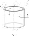
- FIG. 1 shows a cylindrical filter element 1, the filter element body 3 of which is made up of a support body 5 and structural bodies 6, 7.
- a corresponding, coaxially and concentrically positioned hollow-cylindrical structural body 6 , 7 is arranged both on the inner area 14 and on the outer area 13 of the support body 5 .
- the fluid flows 8 through the filter element 1 here, for example, from the outside of the hollow-cylindrical filter element 1 into the inner region of the hollow-cylindrical filter element 1 , after which the fluid is then passed on essentially parallel to the central axis 2 .
- filter elements 1 with structural bodies 6 and support bodies 5 in any geometric configuration can be used.
- Flat and/or cubic filter elements 1 are preferably used here.
- the outer structural body 6 is constructed as a spatially networked lattice structure 15 and is produced by means of a 3D printing process and is oriented essentially parallel to the support body 5 .
- the inner area 19 of the outer structural body 6 is partially in direct contact with the outer area 13 of the support body 5 and is firmly connected to the support body 5 in this contact area. This connection can take place by means of gluing the contact area or by a material connection method of the contact areas.
- Another possibility of connecting both bodies 5, 6 - not shown in the figures - is that the spatially networked lattice structure 15, which consists of rod elements 16, engages with the rod elements 16 through the structure of the support body 5 and in this way the connection of both bodies 5, 6 produces.
- the analogous consideration applies to the outer area 18 of the lattice structure 15 of the inner structural body 7 and the inner area 14 of the supporting body 5, which is in contact at least in certain areas.
- the spatial networking of the rod elements 16 through the cell structure 10 of the support body 5 for connecting the two bodies 5, 7 is possible, the cell structure 10 having a spatial honeycomb structure 11, but also having other shapes of any kind.
- the crosslinking and the mutual dimensionally stable connection of both bodies 6, 7 takes place through the penetration of the rod elements 16 of the lattice structure 15 through cells of the cell structure 10 of the support body 5, with the penetration on the support body 5 through the free space of the cell structure 10 or through the walls of the cell structure 10 , through.
- the supporting body 5 as a supporting body has to hold and support several lattice structures 15, for example, and also has to absorb the forces arising from the flowing fluid, the supporting body 5 is designed in a very stable form.
- the support body 5 has a honeycomb structure, namely the cell structure 10, which has a greater material strength and wall thickness 11 of the honeycomb structure 10 for the purpose of supporting forces.
- rod-shaped cell rods of the cell structure 10 have a larger cross section than the lattice rods 16 of the lattice structure 15. It is also possible that a filament material with higher strength is used when printing the support body 5 and/or during the 3D printing process the Cell structure 10 special, strength-enhancing material components are introduced into the melt of the filament.
- the choice of a possible cell structure 10, in this case a hexagonal honeycomb structure 10, supports the forces in a particularly favorable manner and at the same time generates sufficiently large and regular passages 12 for the fluid flowing through Fluid and the rod elements 16 running through these passages 12, which serve as connections between the support body 5 and the outer structural body 6, or as a connection of an inner structural body 7 with the outer structural body 6 through the support body 5.
- the rod elements 16 protruding through the passage openings 12 of the support body 5 can run directly through the passage opening 12 and/or penetrate areas of the honeycomb structure 10 and are thus firmly connected to it. This penetration of the rod elements 16 and the cell structure 10 additionally strengthens the connection.
- a hollow-cylindrical structural body 6, 7 with a grid structure 15 made up of rod elements or grid rods 16 is 3 pictured.
- the rod elements 16 are here combined in a star and radial shape in a large number of such repeating arrangements and arranged in a chained manner.
- the hollow cylinder shown here shows this crosslinked structure in its longitudinal extension 21 and in its width 20, so that a spatially crosslinked, hollow-cylindrical structural body 6, 7 is formed.
- the star-shaped arranged rod elements 16 create free spaces which are arranged and oriented as meshes 17 or pores 17 in such a way that the fluid to be filtered can optimally flow through the structural body 6, 7. Impurities are retained in the meshes/pores 17 or on the rod elements 16, with the structural body 6, 7 being filled with impurities ensuring sufficient flow through 8 of the structural body 6, 7 for a long time due to the large number of meshes/pores 17, without that the increasing dynamic pressure when flowing through 8 of the structural body 6, 7 reaches critical values.
- the lattice structure 15 is arranged with an adhesive for connection to other coaxially one inside the other, preferably concentrically Structural bodies 6, 7 provided.
- This adhesive can, for example, have been positioned as an additional material with the filament during the printing process in these areas, with subsequent adhesive coating of this inner 14 and outer area 13 being possible.
- substances are introduced into the lattice structure 15 that accumulate in the meshes/pores 17 in order to generate special reactions and/or catalytic effects of the fluid to be filtered there .
- these can be suitable for certain contaminants to adhere permanently to the rod elements 16 and/or to join/chain substances present in the fluid to one another and thus to be able to be filtered out by the lattice structure 15 as contamination.
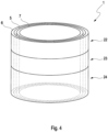
- a hollow-cylindrical filter element 1 made up of support body 5 and structural bodies 6, 7 with a plurality of sections 22, 23, 24 of different lattice structures 15 of the structural body 6, 7 is shown.
- the structural bodies 6, 7 are arranged coaxially, in particular concentrically, one within the other, with the supporting body 5 being positioned between the two structural bodies 6, 7.
- the structural bodies 6, 7 can be divided, for example, in their longitudinal extent 21 into a plurality of sections, in this case three sections 22, 23, 24. With these divisions, the sections 22, 23, 24 consist, for example, of different materials and/or the lattice structure 15 differs in terms of the number of rod elements 16 or the number of meshes/pores 17. It is thus possible for a coarse-meshed lattice structure 15 consisting of a few bar elements 16 to be shown in a first section 22 and for the section 23 adjoining this section 22 to have a finer lattice structure 15 with several shorter bar elements 16 than is present in section 22 .
- the transitions between the individual sections 22, 23, 24 and the different lattice structures 15 can be abruptly or continuously flowing.
- this sectional division of a structural body 6, 7 can be broken down into further concentrically arranged structural bodies 6, 7 and/or also into radial sections, not shown here.
- rough lattice structures 15 can follow on from less rough ones, and these can of course also have abrupt and/or continuous flowing transitions.
- the structural bodies 6, 7 consist of individual lattice structures 15 or of interconnected lattice structures 15 and thus of a plurality of connected structural elements 6, 7.
- sections 22, 23, 24, where the sections 22, 23, 24 can be dimensioned independently of one another and have different dimensions, is important for optimal filtering of the fluid.
- areas of the structural body 6, 7 through which the fluid flows less intensively can be optimally flowed through by the fluid by changing the dynamic pressure by means of larger or smaller meshes/pores 17 and fewer or more rod elements 16 and thereby filter the fluid efficiently.
- the figure 5 shows a hollow-cylindrical filter element 1 made up of supporting body 5 and structural bodies 6, 7, in which the structural bodies 6, 7 are arranged coaxially, preferably concentrically, with respect to one another.
- flow guidance elements 28, so-called guide bodies/flaps 28, are integrated into the lattice structures 15 of the structural bodies 6, 7.
- This guide body 28 are inside or outside the lattice structures 15 of the structural body 6, 7 printed during the 3D printing process.
- Such a guide body 28 positioned at the edge area of the grid body 15 can guide the fluid to be filtered specifically into or to certain areas of the grid body 15 due to its geometric shape and positioning, so that the previously described optimal flow 8 and filter effect of the filter element 1 is achieved.
- a possible effect here can be, for example, a circular turbulence of the fluid in the form or in the manner of a cyclone.
- the targeted guidance of the fluid can also be achieved by means of guide bodies 28 which are arranged inside the grid body 15 and are shaped accordingly.
- These inner guide bodies 28 are also introduced or printed directly into the lattice body 15 during the 3D printing of the latter.
- the guide bodies 28 can be arranged both within the lattice body 15 and between two or more lattice bodies 15 .
- the fluid flowing into a lattice body 15 can be guided very effectively and quickly into other lattice bodies 15 or distributed into them by the guide bodies 28 arranged across them.
- the fluid can also be directed in changing directions and thus into different filter areas by means of a plurality of guide bodies 28 assigned to one another.
- the guide bodies 28 are designed as flat, curved, winding, increasing or decreasing surfaces, with additional integral or molded portions being able to be present on or on the guide bodies 28 to support the guiding function of the fluid.
- solid geometric bodies for example in the shape of a cube, can also be introduced into the grid bodies 15 and the fluid can flow around them as a flow resistance. This creates turbulence which in turn influence the flow behavior of the fluid in such a way that it is directed specifically into certain areas of the filter element 1 and into the grid body 15 .
- a 3D-printed filter unit 30 with a housing 31, flanges 33 and a filter element 1 is shown.
- the outermost structural body 6 is not printed as a lattice body 15 but as a solid body in the form of a housing wall 31 .
- the housing 31 shown essentially corresponds to the geometric shape of the filter element 1 and is solidly constructed as this.
- the housing 31 can also be printed at the same time as the filter element 1 and as a one-piece component.
- Fastening flanges 33 are formed at the ends of the housing 31 and are used, for example, to mount the filter unit 30 on a machine.
- the flanges 33 are designed with fastening bores 35 for assembly using suitable fastening means and have corresponding inlet and outlet openings 34 for the inflow and outflow of the fluid. Both the fastening bores 35 and the inlet and outlet openings 34 are shaped accordingly during the 3D printing process.
- the housing 31 advantageously consists of a material with greater strength, which is produced during the printing process by means of appropriately suitable filaments. It is also conceivable that the filament used here is supplied with corresponding additional materials to increase its strength.
- a possible further embodiment is that the housing 31 as an independent component without a filter element 1 by means of a 3D printing process will be produced.
- the filter element 1 is inserted and positioned in the housing 31 at a later point in time.
- a stop 32 or an insertion limitation 32 can be formed in or on the housing 31 during the 3D printing process.
- the inserted filter element 1 can be fixed in the housing 31, in which case the flange 33 can also serve as a fixation from the insertion side.
- the fastening flanges 33 are attached to the housing 31 again, with one flange being designed so that it can be removed for mounting the filter element 1 .
- the previously produced filter element 1 can of course be pushed into a customary, existing housing 31, in which case instead of the housing 31 a suitable point in a pipeline can also be used. It is thus possible, for example, to be able to use such filter elements 1 at almost any point in a pipe system of a machine/motor.
- This removable flange 33 is subsequently reconnected to the housing 31 in a detachable or fixed manner by means of a suitable connection.
- the particular advantage of such a 3D-printed housing 31 of a filter unit 30 is that the shape and dimensions of the housing 31 can deviate from known symmetrical shapes, and complex housings 31 can be designed with frequently changing shapes.
- the filter elements 1 to be used here correspond to this housing shape. Especially with these filter elements 1 with multiple changing shapes, the figure 5 described guide body 28 of particular interest, so that all important areas of the filter element 1 can be effectively flowed through.
- the respective structural body 6, 7 and the supporting body 5 can be 3D-printed from different materials and/or material compositions be.
- the respective structural body 6, 7 and the supporting body 5 can each be 3D-printed from plastic and/or plastic material.
- the structure of the supporting body 5 has a cell structure 10 which has passages 12 formed by cells.
- the cells are formed with rod-shaped cell columns of the cell structure 10 .
- the meshes/pores 17 of the respective structural body 6, 7 are preferably smaller than the cells or the passages 12 of the support body 5.
- the cells or the passages 12 of the support body 5 can be at least twice, five times or ten times larger than the meshes/pores 17 of the respective structural body 6, 7.
- the lattice bars 16 of the lattice structure 15 of the respective structural body 6, 7 have a smaller cross section than cell bars of the cell structure 10 of the support body 5.
- the cross section of the cell bars of the cell structure 10 of the support body 5 can be at least twice or five times or ten times larger be than the cross section of the lattice bars 16 of the lattice structure 15 of the respective structural body 6, 7.
- a portion of the lattice bars 16 of the lattice structure 15 can enter or penetrate the openings 12 of the cell structure 10 .
- Part of the lattice rods 16 of the lattice structure 15 can preferably penetrate into the passages 12 of the cell structure 10 or penetrate them in such a way that the lattice structure 15 is fixed to the cell structure 10 in a form-fitting manner. A further additional fixation by fusible links can then be unnecessary.
- the filter element 1 can be designed as a ring filter element 40 in which the respective structural body 6, 7 and the support body 5 form a ring-shaped ring filter body 41.
- the filter element body 3 is ring-shaped and forms said ring filter body 41.
- the filter element 1 or the ring filter element 40 also has two end plates 42, 43, which are each arranged at an axial end of the ring filter body 41.
- the upper end disk 42 is designed as an open end disk and accordingly has a central passage opening 44 which is open towards an interior space 45 enclosed by the ring filter body 41 .
- Lower end plate 43 can also be configured as an open end plate.
- the lower end disk 43 can also be designed as a closed end disk, which closes the interior space 45 axially.
- At least one of the end plates 42, 43 can be printed onto the ring filter body 41 by means of 3D printing.
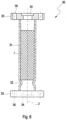
- FIG. 7 accordingly shows a ring filter element 40, in particular for a filter unit 30 for filtering a fluid, the ring filter element 40 being equipped with a ring-shaped ring filter body 41, which is formed by a filter element 1 of the type described above, and with two end plates 42, 43, each of which an axial end of the ring filter body 41 are arranged.
- the flow through the ring filter body 41 is radial.
- cleaned fluid can be discharged or uncleaned fluid can be supplied through the passage opening 44 .
- the axial direction of the ring filter element 40 is defined by its longitudinal central axis 46 .
Claims (15)
- Élément filtrant (1) pour une unité de filtre (30) pour la filtration d'un fluide,- dans lequel l'élément filtrant (1) présente un corps d'élément filtrant (3) traversable par le fluide avec au moins un corps structurel (6, 7) et un corps d'appui (5),- dans lequel le corps structurel (6, 7) respectif présente une structure de filtre perméable au fluide avec une pluralité de mailles/pores (17),- dans lequel la structure de filtre est réalisée comme structure treillissée (15) réticulée dans l'espace et la structure treillissée (15) réticulée dans l'espace présente une régularité se répétant,- dans lequel les mailles/pores (17) sont formés comme espaces libres par des barres de treillis (16) reliées fixement entre elles,- dans lequel le corps d'appui (5) présente une structure d'appui perméable au fluide,- dans lequel le corps structurel (6, 7) respectif et le corps d'appui (5) sont fabriqués respectivement au moyen d'un procédé d'impression 3D,caractérisé en ce que
le corps structurel (6, 7) respectif et le corps d'appui (5) sont imprimés en 3D en différents matériaux et/ou compositions de matériau. - Élément filtrant (1) selon la revendication 1,
caractérisé en ce que
le corps structurel (6, 7) respectif et le corps d'appui (5) sont imprimés en 3D respectivement en matière plastique et/ou matériau plastique. - Élément filtrant (1) selon l'une quelconque des revendications précédentes,
caractérisé en ce que- la structure du corps d'appui (5) présente une structure de cellule (10) qui présente des passages (12) formés par des cellules, dans lequel les mailles/pores (17) du corps structurel (6, 7) respectif sont inférieures aux cellules ou aux passages (12) du corps structurel (5), et/ou- la structure du corps d'appui (5) présente une structure de cellule (10) qui présente des passages (12) formés par des cellules, dans lequel des barres de treillis (16) de la structure treillissée (15) du corps structurel (6, 7) respectif présentent une section transversale inférieure à celle des barres de cellule de la structure de cellule du corps d'appui (5). - Élément filtrant (1) selon la revendication 3,
caractérisé en ce que- les cellules ou les passages (12) du corps d'appui (5) sont au moins deux fois ou cinq fois ou dix fois plus grands que les mailles/pores (17) du corps structurel (6, 7) respectif, et/ou- la section transversale des barres de cellule de la structure de cellule du corps d'appui (5) sont au moins deux fois ou cinq fois ou dix fois plus grande que la section transversale des barres de treillis (16) de la structure treillissée (15) du corps structurel (6, 7) respectif. - Élément filtrant (1) selon l'une quelconque des revendications précédentes,
caractérisé en ce que- la structure du corps d'appui (5) présente une structure de cellule (10) qui présente des passages (12) formés par des cellules,- une partie des barres de treillis (16) de la structure treillissée (15) pénètre dans les passages (12) de la structure de cellule (10) ou les traversent. - Élément filtrant (1) selon la revendication 5,
caractérisé en ce que
une partie des barres de treillis (16) de la structure treillissée (15) pénètre dans les passages (12) de la structure de cellule (10) ou les traverse de sorte que la structure treillissée (15) soit fixée par complémentarité de formes à la structure de cellule (10). - Élément filtrant selon l'une quelconque des revendications 3 à 6,
caractérisé en ce que- seul un unique corps structurel (6, 7) est prévu, dans lequel la structure de cellule du corps d'appui (5) est agencée à l'intérieur de la structure treillissée (15) de ce corps structurel (6, 7), dans lequel certaines des barres de treillis (16) traversent les cellules, ou- deux corps structurels (6, 7) agencés coaxialement l'un dans l'autre sont prévus et le corps d'appui (5) est agencé entre les deux corps structurels (6, 7), dans lequel certaines des barres de treillis (16) traversent les cellules de la structure de cellule (10) du corps d'appui (5) et relient les deux corps structurels (6, 7) entre eux. - Élément filtrant (1) selon l'une quelconque des revendications précédentes,
caractérisé en ce que- le corps structurel (6, 7) respectif et le corps d'appui (5) sont configurés en forme de cylindre creux et sont agencés coaxialement l'un dans l'autre, de préférence concentriquement l'un à l'autre, dans lequel le corps structurel (6, 7) respectif et le corps d'appui (5) sont agencés au moins approximativement parallèlement l'un à l'autre, et/ou- le corps d'appui (6, 7) respectif est relié fixement au corps d'appui (5), dans lequel la liaison fixe entre les corps structurels (6, 7) respectifs et le corps d'appui (5) est formée par une liaison de matière. - Élément filtrant (1) selon l'une quelconque des revendications précédentes,
caractérisé en ce que- d'autres corps structurels (6, 7) sont prévus au niveau de deux corps structurels (6, 7) agencés coaxialement l'un dans l'autre,- un autre corps structurel (6) est avec sa zone intérieure (19) en contact direct avec la zone extérieure (18) du corps structurel (7) et est relié fixement à celui-ci,- un autre corps structurel (7) est avec sa zone extérieure (18) en contact direct avec la zone intérieure (19) du corps structurel (7) et est relié fixement à celui-ci,- en particulier il peut être prévu que les corps structurels (6, 7) se traversent en chevauchant au moins par endroits entre eux sur leurs zones (18) extérieures et zones (19) intérieures. - Élément filtrant (1) selon l'une quelconque des revendications précédentes,
caractérisé en ce que- dans les mailles/pores (17) formés par les barres de treillis (16) reliées fixement et réticulées, des matériaux/substances réactifs ou agissant sur le fluide de manière catalytique sont intégrés, dans lequel le fluide à filtrer présente une action coalescente pour la formation de particules séparables, et/ou- les mailles/pores (17) formés par les barres de treillis (16) reliées du corps d'appui (5) présentent pour la filtration de fluides liquides respectivement des longueurs d'arête de 0,05 mm à 15 mm, de préférence de 0,1 mm à 10 mm, ou pour la filtration de fluides gazeux respectivement des longueurs d'arête de 0,1 mm à 40 mm, de préférence de 4 mm à 20 mm. - Élément filtrant (1) selon l'une quelconque des revendications précédentes,
caractérisé en ce que- plusieurs corps structurels (6, 7) contigus présentent des structures de treillis (15) réticulées différentes les unes des autres,- plusieurs corps structurels (6, 7) contigus présentent des propriétés de matériau différentes les unes des autres des structures treillissées (15) réticulées,- les structures treillissées (15) différentes les unes des autres réticulées et les propriétés de matériau différentes les unes des autres des structures treillissées (15) réticulées se modifient brusquement ou en continu,- en particulier il peut être prévu que le corps structurel (6, 7) respectif et le corps d'appui (5) soient fabriqués respectivement en une pièce. - Élément filtrant (1) selon l'une quelconque des revendications précédentes,
caractérisé en ce que- des éléments de guidage d'écoulement/corps de conduite (28) sont réalisés au niveau et/ou dans le corps structurel (6, 7) et le corps d'appui (5),- les éléments de guidage d'écoulement/corps de conduite (28) sont réalisés chevauchant d'autres corps structurels (6, 7) et/ou le corps d'appui (5),- les éléments de guidage d'écoulement/corps de conduite (28) présentent une forme plane et/ou courbée et/ou enroulée,- les éléments de guidage d'écoulement/corps de conduite (28) se modifient dans leur forme brusquement ou en continu. - Élément filtrant (1) selon l'une quelconque des revendications précédentes,
caractérisé en ce que- l'élément filtrant (1) est configuré comme élément filtrant annulaire (40), pour lequel le corps structurel (6, 7) respectif et le corps d'appui (5) forment un corps de filtre annulaire (41) annulaire ou au moins une partie annulaire de celui-ci,- l'élément filtrant (1) présente en outre deux disques d'extrémité (42, 43) qui sont agencés respectivement à une extrémité axiale du corps de filtre annulaire (41). - Élément filtrant annulaire (40) pour une unité de filtre (30) pour la filtration d'un fluide,- avec un corps de filtre annulaire (41) annulaire qui présente un élément filtrant (1) selon l'une quelconque des revendications précédentes ou est formé par celui-ci,- avec deux disques d'extrémité (42, 43) qui sont agencés respectivement à une extrémité axiale du corps de filtre annulaire (41).
- Unité de filtre (30) avec un boîtier (31) et avec un élément filtrant (1) inséré dans le boîtier (31) selon l'une ou plusieurs quelconques des revendications précédentes.
Applications Claiming Priority (2)
| Application Number | Priority Date | Filing Date | Title |
|---|---|---|---|
| DE102019207003.5A DE102019207003B4 (de) | 2019-05-14 | 2019-05-14 | Filterelement für eine Filtereinheit und Filtereinheit |
| PCT/EP2020/057785 WO2020229026A1 (fr) | 2019-05-14 | 2020-03-20 | Élément filtrant conçu pour un ensemble filtre |
Publications (3)
| Publication Number | Publication Date |
|---|---|
| EP3969147A1 EP3969147A1 (fr) | 2022-03-23 |
| EP3969147C0 EP3969147C0 (fr) | 2023-06-14 |
| EP3969147B1 true EP3969147B1 (fr) | 2023-06-14 |
Family
ID=70008476
Family Applications (1)
| Application Number | Title | Priority Date | Filing Date |
|---|---|---|---|
| EP20714508.7A Active EP3969147B1 (fr) | 2019-05-14 | 2020-03-20 | Élément filtrant conçu pour un ensemble filtre |
Country Status (6)
| Country | Link |
|---|---|
| US (1) | US20220143533A1 (fr) |
| EP (1) | EP3969147B1 (fr) |
| CN (1) | CN113825552A (fr) |
| DE (1) | DE102019207003B4 (fr) |
| PL (1) | PL3969147T3 (fr) |
| WO (1) | WO2020229026A1 (fr) |
Family Cites Families (17)
| Publication number | Priority date | Publication date | Assignee | Title |
|---|---|---|---|---|
| FI900719A0 (fi) * | 1989-08-24 | 1990-02-14 | Albany Int Corp | Filter. |
| CN2068414U (zh) * | 1990-06-08 | 1991-01-02 | 双鸭山矿务局选煤厂 | 一种过滤机金属扇叶 |
| US5662728A (en) | 1992-12-31 | 1997-09-02 | Hoechst Celanese Corporation | Particulate filter structure |
| CN100542674C (zh) * | 2003-06-10 | 2009-09-23 | 揖斐电株式会社 | 蜂窝状结构体 |
| DE102009023951B3 (de) * | 2009-06-04 | 2011-01-05 | Mann + Hummel Gmbh | Filtereinrichtung zur Flüssigkeitsfiltrierung |
| DE102010051756B4 (de) * | 2010-11-17 | 2021-01-21 | Robert Bosch Gmbh | Filtereinsatz |
| CN105102099B (zh) | 2013-03-15 | 2018-10-19 | 派罗特克公司 | 陶瓷过滤器 |
| EP3065791B1 (fr) | 2013-11-05 | 2023-04-12 | President and Fellows of Harvard College | Procédé d'impression d'une construction tissulaire à vasculature intégrée |
| CN105041529A (zh) * | 2015-06-24 | 2015-11-11 | 广东信达雅三维科技有限公司 | 一种过滤器及其激光打印制备方法和应用 |
| CN206214865U (zh) * | 2016-06-30 | 2017-06-06 | 中天储能科技有限公司 | 一种锂电池浆料过滤的滤芯 |
| KR101875838B1 (ko) * | 2016-09-08 | 2018-07-06 | 전남대학교산학협력단 | 3차원 다공성 구조체를 이용한 유증기 필터 및 이를 구비한 공기정화장치 |
| DE202016105013U1 (de) * | 2016-09-09 | 2016-09-23 | Nordson Corporation | Filterkerze zum Abscheiden von Verunreinigungen aus einer Kunststoffschmelze |
| US10359128B2 (en) * | 2016-10-21 | 2019-07-23 | Emerson Process Management Regulator Technologies, Inc. | Lattice control cage for a regulator |
| JPWO2018122985A1 (ja) * | 2016-12-27 | 2019-10-31 | 武藤工業株式会社 | フィルタ及びその製造方法、並びに分級機 |
| US10413852B2 (en) * | 2017-03-29 | 2019-09-17 | Pall Corporation | Filter, filter device, and method of use |
| DE202017104240U1 (de) | 2017-07-17 | 2017-08-03 | Ask Chemicals L.P. | Vorstufe für einen keramischen Filter und keramisches Filter |
| CN108568160A (zh) * | 2018-04-04 | 2018-09-25 | 华南理工大学 | 一种高温镍基合金多级过滤器及制造方法 |
-
2019
- 2019-05-14 DE DE102019207003.5A patent/DE102019207003B4/de active Active
-
2020
- 2020-03-20 EP EP20714508.7A patent/EP3969147B1/fr active Active
- 2020-03-20 CN CN202080036243.4A patent/CN113825552A/zh active Pending
- 2020-03-20 PL PL20714508.7T patent/PL3969147T3/pl unknown
- 2020-03-20 US US17/611,043 patent/US20220143533A1/en not_active Abandoned
- 2020-03-20 WO PCT/EP2020/057785 patent/WO2020229026A1/fr active Search and Examination
Also Published As
| Publication number | Publication date |
|---|---|
| CN113825552A (zh) | 2021-12-21 |
| US20220143533A1 (en) | 2022-05-12 |
| EP3969147C0 (fr) | 2023-06-14 |
| EP3969147A1 (fr) | 2022-03-23 |
| DE102019207003A1 (de) | 2020-11-19 |
| PL3969147T3 (pl) | 2023-12-27 |
| WO2020229026A1 (fr) | 2020-11-19 |
| DE102019207003B4 (de) | 2022-07-07 |
Similar Documents
| Publication | Publication Date | Title |
|---|---|---|
| EP3064262B1 (fr) | Milieu filtrant, procede de fabrication d'un milieu filtrant et element de filtre comprenant un milieu filtrant | |
| DE60021055T2 (de) | Gefaltetes filterelement und verfahren zur herstellung eines gefalteten filterelements | |
| EP0982433B1 (fr) | Tambour cylindrique pour un appareil de tamisage sous pression comportant un tamis cylindrique remplaçable | |
| DE2645634A1 (de) | Von innen nach aussen durchstroemtes rohrfilter und verfahren zu seiner herstellung | |
| WO2002000326A2 (fr) | Piege a particules destine a extraire des particules d'un courant de fluide, procede d'extraction de particules d'un courant de fluide, et utilisation d'un piege a particules | |
| DE102011009325B4 (de) | Verfahren und Formvorrichtung zum Herstellen eines Filterelements | |
| EP3017854A1 (fr) | Élément creux d'un filtre destiné à filtrer un fluide, filtre, carter de filtre et joint d'un élément creux de filtre | |
| EP2978550A1 (fr) | Système de filtration slm | |
| EP3969147B1 (fr) | Élément filtrant conçu pour un ensemble filtre | |
| WO2019020442A1 (fr) | Filtre à liquide et système filtrant de réservoir pourvu d'un filtre à liquide | |
| WO1992001500A1 (fr) | Dispositif de filtration pour matiere thermoplastique | |
| DE69935432T2 (de) | Filterelement und verfahren zu seiner herstellung | |
| DE10116408C1 (de) | Vorrichtung zum Filtrieren einer Flüssigkeit, insbesondere zum Filtrieren einer polymeren Kunststoffschmelze | |
| EP2059378B1 (fr) | Dispositif de filtration de matière synthétique thermoplastique fondue | |
| DE602004006611T2 (de) | Stabsiebkorb zur Filtrierung von Fasersuspensionen und Verfahren zu dessen Herstellung | |
| EP4234207A1 (fr) | Unité de filtre pour une installation d'extrusion, agencement de filtre et dispositif de changement de tamis associé, ainsi que procédé de fabrication d'une telle unité de filtre | |
| DE102013018199B4 (de) | Flüssigkeitsfilter, insbesondere für Kraftstoff | |
| DE19922326A1 (de) | Mehrlagiges Filtermedium | |
| EP2892629B1 (fr) | Element filtrant | |
| WO2012085052A1 (fr) | Élément de filtration | |
| DE19630852A1 (de) | Filter mit einem offenporigen Element aus Sintermaterial | |
| DE2322386A1 (de) | Patronenfilterelement und verfahren zur herstellung desselben | |
| WO2007014602A2 (fr) | Element filtre et dispositif associe | |
| EP1543871B1 (fr) | Filtre avec élément filtrant et utilisation d'un tel filtre | |
| DE102011001017B4 (de) | Rückspülbare Filtereinheit für ein Siebträgerelement für eine Filtriereinrichtung |
Legal Events
| Date | Code | Title | Description |
|---|---|---|---|
| STAA | Information on the status of an ep patent application or granted ep patent |
Free format text: STATUS: UNKNOWN |
|
| STAA | Information on the status of an ep patent application or granted ep patent |
Free format text: STATUS: THE INTERNATIONAL PUBLICATION HAS BEEN MADE |
|
| PUAI | Public reference made under article 153(3) epc to a published international application that has entered the european phase |
Free format text: ORIGINAL CODE: 0009012 |
|
| STAA | Information on the status of an ep patent application or granted ep patent |
Free format text: STATUS: REQUEST FOR EXAMINATION WAS MADE |
|
| 17P | Request for examination filed |
Effective date: 20211129 |
|
| AK | Designated contracting states |
Kind code of ref document: A1 Designated state(s): AL AT BE BG CH CY CZ DE DK EE ES FI FR GB GR HR HU IE IS IT LI LT LU LV MC MK MT NL NO PL PT RO RS SE SI SK SM TR |
|
| DAV | Request for validation of the european patent (deleted) | ||
| DAX | Request for extension of the european patent (deleted) | ||
| GRAP | Despatch of communication of intention to grant a patent |
Free format text: ORIGINAL CODE: EPIDOSNIGR1 |
|
| STAA | Information on the status of an ep patent application or granted ep patent |
Free format text: STATUS: GRANT OF PATENT IS INTENDED |
|
| INTG | Intention to grant announced |
Effective date: 20230210 |
|
| GRAS | Grant fee paid |
Free format text: ORIGINAL CODE: EPIDOSNIGR3 |
|
| GRAA | (expected) grant |
Free format text: ORIGINAL CODE: 0009210 |
|
| STAA | Information on the status of an ep patent application or granted ep patent |
Free format text: STATUS: THE PATENT HAS BEEN GRANTED |
|
| AK | Designated contracting states |
Kind code of ref document: B1 Designated state(s): AL AT BE BG CH CY CZ DE DK EE ES FI FR GB GR HR HU IE IS IT LI LT LU LV MC MK MT NL NO PL PT RO RS SE SI SK SM TR |
|
| REG | Reference to a national code |
Ref country code: CH Ref legal event code: EP |
|
| REG | Reference to a national code |
Ref country code: DE Ref legal event code: R096 Ref document number: 502020003789 Country of ref document: DE |
|
| REG | Reference to a national code |
Ref country code: AT Ref legal event code: REF Ref document number: 1578810 Country of ref document: AT Kind code of ref document: T Effective date: 20230715 |
|
| U01 | Request for unitary effect filed |
Effective date: 20230711 |
|
| U07 | Unitary effect registered |
Designated state(s): AT BE BG DE DK EE FI FR IT LT LU LV MT NL PT SE SI Effective date: 20230720 |
|
| REG | Reference to a national code |
Ref country code: LT Ref legal event code: MG9D |
|
| PG25 | Lapsed in a contracting state [announced via postgrant information from national office to epo] |
Ref country code: NO Free format text: LAPSE BECAUSE OF FAILURE TO SUBMIT A TRANSLATION OF THE DESCRIPTION OR TO PAY THE FEE WITHIN THE PRESCRIBED TIME-LIMIT Effective date: 20230914 Ref country code: ES Free format text: LAPSE BECAUSE OF FAILURE TO SUBMIT A TRANSLATION OF THE DESCRIPTION OR TO PAY THE FEE WITHIN THE PRESCRIBED TIME-LIMIT Effective date: 20230614 |
|
| PG25 | Lapsed in a contracting state [announced via postgrant information from national office to epo] |
Ref country code: RS Free format text: LAPSE BECAUSE OF FAILURE TO SUBMIT A TRANSLATION OF THE DESCRIPTION OR TO PAY THE FEE WITHIN THE PRESCRIBED TIME-LIMIT Effective date: 20230614 Ref country code: HR Free format text: LAPSE BECAUSE OF FAILURE TO SUBMIT A TRANSLATION OF THE DESCRIPTION OR TO PAY THE FEE WITHIN THE PRESCRIBED TIME-LIMIT Effective date: 20230614 Ref country code: GR Free format text: LAPSE BECAUSE OF FAILURE TO SUBMIT A TRANSLATION OF THE DESCRIPTION OR TO PAY THE FEE WITHIN THE PRESCRIBED TIME-LIMIT Effective date: 20230915 |
|
| PG25 | Lapsed in a contracting state [announced via postgrant information from national office to epo] |
Ref country code: SK Free format text: LAPSE BECAUSE OF FAILURE TO SUBMIT A TRANSLATION OF THE DESCRIPTION OR TO PAY THE FEE WITHIN THE PRESCRIBED TIME-LIMIT Effective date: 20230614 |
|
| PG25 | Lapsed in a contracting state [announced via postgrant information from national office to epo] |
Ref country code: IS Free format text: LAPSE BECAUSE OF FAILURE TO SUBMIT A TRANSLATION OF THE DESCRIPTION OR TO PAY THE FEE WITHIN THE PRESCRIBED TIME-LIMIT Effective date: 20231014 |
|
| PG25 | Lapsed in a contracting state [announced via postgrant information from national office to epo] |
Ref country code: SM Free format text: LAPSE BECAUSE OF FAILURE TO SUBMIT A TRANSLATION OF THE DESCRIPTION OR TO PAY THE FEE WITHIN THE PRESCRIBED TIME-LIMIT Effective date: 20230614 Ref country code: SK Free format text: LAPSE BECAUSE OF FAILURE TO SUBMIT A TRANSLATION OF THE DESCRIPTION OR TO PAY THE FEE WITHIN THE PRESCRIBED TIME-LIMIT Effective date: 20230614 Ref country code: RO Free format text: LAPSE BECAUSE OF FAILURE TO SUBMIT A TRANSLATION OF THE DESCRIPTION OR TO PAY THE FEE WITHIN THE PRESCRIBED TIME-LIMIT Effective date: 20230614 Ref country code: IS Free format text: LAPSE BECAUSE OF FAILURE TO SUBMIT A TRANSLATION OF THE DESCRIPTION OR TO PAY THE FEE WITHIN THE PRESCRIBED TIME-LIMIT Effective date: 20231014 Ref country code: CZ Free format text: LAPSE BECAUSE OF FAILURE TO SUBMIT A TRANSLATION OF THE DESCRIPTION OR TO PAY THE FEE WITHIN THE PRESCRIBED TIME-LIMIT Effective date: 20230614 |