EP3969147B1 - Filter element for a filter unit - Google Patents
Filter element for a filter unit Download PDFInfo
- Publication number
- EP3969147B1 EP3969147B1 EP20714508.7A EP20714508A EP3969147B1 EP 3969147 B1 EP3969147 B1 EP 3969147B1 EP 20714508 A EP20714508 A EP 20714508A EP 3969147 B1 EP3969147 B1 EP 3969147B1
- Authority
- EP
- European Patent Office
- Prior art keywords
- filter element
- support body
- lattice
- structural
- filter
- Prior art date
- Legal status (The legal status is an assumption and is not a legal conclusion. Google has not performed a legal analysis and makes no representation as to the accuracy of the status listed.)
- Active
Links
- 239000012530 fluid Substances 0.000 claims description 58
- 239000000463 material Substances 0.000 claims description 49
- 238000000034 method Methods 0.000 claims description 34
- 238000010146 3D printing Methods 0.000 claims description 27
- 239000011148 porous material Substances 0.000 claims description 26
- 238000001914 filtration Methods 0.000 claims description 18
- 230000000694 effects Effects 0.000 claims description 14
- 239000002245 particle Substances 0.000 claims description 14
- 239000004033 plastic Substances 0.000 claims description 7
- 230000008859 change Effects 0.000 claims description 5
- 239000000203 mixture Substances 0.000 claims description 4
- 230000003197 catalytic effect Effects 0.000 claims description 3
- 239000007788 liquid Substances 0.000 claims description 3
- 239000000126 substance Substances 0.000 claims description 3
- 210000004027 cell Anatomy 0.000 description 49
- 230000008093 supporting effect Effects 0.000 description 30
- 230000008569 process Effects 0.000 description 26
- 239000000835 fiber Substances 0.000 description 19
- 238000007639 printing Methods 0.000 description 9
- 239000000853 adhesive Substances 0.000 description 7
- 230000001070 adhesive effect Effects 0.000 description 7
- 238000013461 design Methods 0.000 description 5
- 210000001519 tissue Anatomy 0.000 description 5
- 239000002131 composite material Substances 0.000 description 4
- 238000011109 contamination Methods 0.000 description 4
- 239000004744 fabric Substances 0.000 description 4
- 230000035515 penetration Effects 0.000 description 4
- 239000007787 solid Substances 0.000 description 4
- 230000007704 transition Effects 0.000 description 4
- 238000011161 development Methods 0.000 description 3
- 238000003780 insertion Methods 0.000 description 3
- 230000037431 insertion Effects 0.000 description 3
- 238000009434 installation Methods 0.000 description 3
- 238000004519 manufacturing process Methods 0.000 description 3
- 238000002844 melting Methods 0.000 description 3
- 230000000149 penetrating effect Effects 0.000 description 3
- 238000007669 thermal treatment Methods 0.000 description 3
- OKTJSMMVPCPJKN-UHFFFAOYSA-N Carbon Chemical compound [C] OKTJSMMVPCPJKN-UHFFFAOYSA-N 0.000 description 2
- VYPSYNLAJGMNEJ-UHFFFAOYSA-N Silicium dioxide Chemical compound O=[Si]=O VYPSYNLAJGMNEJ-UHFFFAOYSA-N 0.000 description 2
- 239000011149 active material Substances 0.000 description 2
- 238000004026 adhesive bonding Methods 0.000 description 2
- 230000008901 benefit Effects 0.000 description 2
- 238000009826 distribution Methods 0.000 description 2
- 239000012535 impurity Substances 0.000 description 2
- 230000008018 melting Effects 0.000 description 2
- 229910052751 metal Inorganic materials 0.000 description 2
- 239000002184 metal Substances 0.000 description 2
- 238000001179 sorption measurement Methods 0.000 description 2
- 229920001169 thermoplastic Polymers 0.000 description 2
- 239000004416 thermosoftening plastic Substances 0.000 description 2
- 230000002792 vascular Effects 0.000 description 2
- 238000004804 winding Methods 0.000 description 2
- 102000010834 Extracellular Matrix Proteins Human genes 0.000 description 1
- 108010037362 Extracellular Matrix Proteins Proteins 0.000 description 1
- 229910021536 Zeolite Inorganic materials 0.000 description 1
- 239000000654 additive Substances 0.000 description 1
- 239000001913 cellulose Substances 0.000 description 1
- 229920002678 cellulose Polymers 0.000 description 1
- 239000000919 ceramic Substances 0.000 description 1
- 238000006243 chemical reaction Methods 0.000 description 1
- 239000004927 clay Substances 0.000 description 1
- 239000011248 coating agent Substances 0.000 description 1
- 238000000576 coating method Methods 0.000 description 1
- 239000000356 contaminant Substances 0.000 description 1
- 238000004132 cross linking Methods 0.000 description 1
- 230000003247 decreasing effect Effects 0.000 description 1
- 230000001419 dependent effect Effects 0.000 description 1
- HNPSIPDUKPIQMN-UHFFFAOYSA-N dioxosilane;oxo(oxoalumanyloxy)alumane Chemical compound O=[Si]=O.O=[Al]O[Al]=O HNPSIPDUKPIQMN-UHFFFAOYSA-N 0.000 description 1
- 210000002744 extracellular matrix Anatomy 0.000 description 1
- 230000002349 favourable effect Effects 0.000 description 1
- 230000004927 fusion Effects 0.000 description 1
- 239000008187 granular material Substances 0.000 description 1
- 238000010438 heat treatment Methods 0.000 description 1
- 230000002209 hydrophobic effect Effects 0.000 description 1
- 230000003993 interaction Effects 0.000 description 1
- 230000001788 irregular Effects 0.000 description 1
- 239000011344 liquid material Substances 0.000 description 1
- 239000000155 melt Substances 0.000 description 1
- 230000006855 networking Effects 0.000 description 1
- 238000005457 optimization Methods 0.000 description 1
- TWNQGVIAIRXVLR-UHFFFAOYSA-N oxo(oxoalumanyloxy)alumane Chemical compound O=[Al]O[Al]=O TWNQGVIAIRXVLR-UHFFFAOYSA-N 0.000 description 1
- 230000035699 permeability Effects 0.000 description 1
- 239000004848 polyfunctional curative Substances 0.000 description 1
- 210000001316 polygonal cell Anatomy 0.000 description 1
- 229920000642 polymer Polymers 0.000 description 1
- 238000012545 processing Methods 0.000 description 1
- 239000002994 raw material Substances 0.000 description 1
- 230000003252 repetitive effect Effects 0.000 description 1
- 230000000717 retained effect Effects 0.000 description 1
- 238000007493 shaping process Methods 0.000 description 1
- 239000000377 silicon dioxide Substances 0.000 description 1
- 235000012239 silicon dioxide Nutrition 0.000 description 1
- 239000003381 stabilizer Substances 0.000 description 1
- 210000005166 vasculature Anatomy 0.000 description 1
- 239000010457 zeolite Substances 0.000 description 1
Images


Classifications
-
- B—PERFORMING OPERATIONS; TRANSPORTING
- B01—PHYSICAL OR CHEMICAL PROCESSES OR APPARATUS IN GENERAL
- B01D—SEPARATION
- B01D29/00—Filters with filtering elements stationary during filtration, e.g. pressure or suction filters, not covered by groups B01D24/00 - B01D27/00; Filtering elements therefor
- B01D29/11—Filters with filtering elements stationary during filtration, e.g. pressure or suction filters, not covered by groups B01D24/00 - B01D27/00; Filtering elements therefor with bag, cage, hose, tube, sleeve or like filtering elements
- B01D29/111—Making filtering elements
-
- B—PERFORMING OPERATIONS; TRANSPORTING
- B01—PHYSICAL OR CHEMICAL PROCESSES OR APPARATUS IN GENERAL
- B01D—SEPARATION
- B01D29/00—Filters with filtering elements stationary during filtration, e.g. pressure or suction filters, not covered by groups B01D24/00 - B01D27/00; Filtering elements therefor
- B01D29/11—Filters with filtering elements stationary during filtration, e.g. pressure or suction filters, not covered by groups B01D24/00 - B01D27/00; Filtering elements therefor with bag, cage, hose, tube, sleeve or like filtering elements
- B01D29/13—Supported filter elements
- B01D29/15—Supported filter elements arranged for inward flow filtration
-
- B—PERFORMING OPERATIONS; TRANSPORTING
- B01—PHYSICAL OR CHEMICAL PROCESSES OR APPARATUS IN GENERAL
- B01D—SEPARATION
- B01D29/00—Filters with filtering elements stationary during filtration, e.g. pressure or suction filters, not covered by groups B01D24/00 - B01D27/00; Filtering elements therefor
- B01D29/50—Filters with filtering elements stationary during filtration, e.g. pressure or suction filters, not covered by groups B01D24/00 - B01D27/00; Filtering elements therefor with multiple filtering elements, characterised by their mutual disposition
- B01D29/56—Filters with filtering elements stationary during filtration, e.g. pressure or suction filters, not covered by groups B01D24/00 - B01D27/00; Filtering elements therefor with multiple filtering elements, characterised by their mutual disposition in series connection
- B01D29/58—Filters with filtering elements stationary during filtration, e.g. pressure or suction filters, not covered by groups B01D24/00 - B01D27/00; Filtering elements therefor with multiple filtering elements, characterised by their mutual disposition in series connection arranged concentrically or coaxially
-
- B—PERFORMING OPERATIONS; TRANSPORTING
- B01—PHYSICAL OR CHEMICAL PROCESSES OR APPARATUS IN GENERAL
- B01D—SEPARATION
- B01D29/00—Filters with filtering elements stationary during filtration, e.g. pressure or suction filters, not covered by groups B01D24/00 - B01D27/00; Filtering elements therefor
- B01D29/88—Filters with filtering elements stationary during filtration, e.g. pressure or suction filters, not covered by groups B01D24/00 - B01D27/00; Filtering elements therefor having feed or discharge devices
- B01D29/90—Filters with filtering elements stationary during filtration, e.g. pressure or suction filters, not covered by groups B01D24/00 - B01D27/00; Filtering elements therefor having feed or discharge devices for feeding
- B01D29/902—Filters with filtering elements stationary during filtration, e.g. pressure or suction filters, not covered by groups B01D24/00 - B01D27/00; Filtering elements therefor having feed or discharge devices for feeding containing fixed liquid displacement elements or cores
-
- B—PERFORMING OPERATIONS; TRANSPORTING
- B33—ADDITIVE MANUFACTURING TECHNOLOGY
- B33Y—ADDITIVE MANUFACTURING, i.e. MANUFACTURING OF THREE-DIMENSIONAL [3-D] OBJECTS BY ADDITIVE DEPOSITION, ADDITIVE AGGLOMERATION OR ADDITIVE LAYERING, e.g. BY 3-D PRINTING, STEREOLITHOGRAPHY OR SELECTIVE LASER SINTERING
- B33Y80/00—Products made by additive manufacturing
-
- B—PERFORMING OPERATIONS; TRANSPORTING
- B01—PHYSICAL OR CHEMICAL PROCESSES OR APPARATUS IN GENERAL
- B01D—SEPARATION
- B01D2201/00—Details relating to filtering apparatus
- B01D2201/18—Filters characterised by the openings or pores
- B01D2201/184—Special form, dimension of the openings, pores of the filtering elements
-
- B—PERFORMING OPERATIONS; TRANSPORTING
- B01—PHYSICAL OR CHEMICAL PROCESSES OR APPARATUS IN GENERAL
- B01D—SEPARATION
- B01D2201/00—Details relating to filtering apparatus
- B01D2201/18—Filters characterised by the openings or pores
- B01D2201/188—Multiple filtering elements having filtering areas of different size
Definitions
- the present invention relates to a filter element for a filter unit for filtering a fluid according to the preamble of claim 1.
- the invention also relates to a filter unit with such a filter element.
- filter elements are used in corresponding filter units, which have a filter body with a filter material for particle filtration.
- These filter materials have filter structures made of suitable materials.
- filter structures made of fabric and/or cellulose materials are used, which have material-related limited filter properties and can only be brought into complex shapes to a limited extent.
- Such filter elements have a predetermined and unchangeable filter characteristic, which only allows limited optimization of the fluid to be filtered.
- a filter material for sorption filtration with a filter structure consisting of particles is known, which is formed by a fibrous three-dimensional structure of composite fibers.
- these composite fibers have a further first component with a melting point that is approx. 20°C lower than the structural component, so that this first component can melt with a corresponding thermal treatment and thus crossing or touching structural components can connect to one another .
- the filter element has a 3D-printed uniform flat structural body for filtering the molten metal and a 3D-printed uniform support body that closes the structural body bordered circumferentially and thereby forms a kind of cage for holding the structural body.
- the fibrous three-dimensional structure is composed of structural fibers of different dimensions, in particular different fiber thicknesses, which all have the previously described property of a further first component and are connected to one another by the thermal treatment mentioned.
- the fibrous three-dimensional framework of composite fibers consists of structural fibers of different dimensions, which are more or less freely arranged and connected to one another but do not have any regular, repeating structures.
- the thicker structural fibers take on a kind of supporting effect for the filter structure, with the thinner structural fibers taking on the actual, essential filter function. It is possible that both the thicker and the thinner structural fibers are made of the same material.
- finer structural fibers are dispersed in a framework of coarser structural fibers, for example by hydro-interlacing or by air-interlacing.
- a finer fabric can be formed from thermoplastic structural fibers and then a fabric with coarser structural fibers can be installed to achieve filter stability.
- the connected structural fibers create cavities in which functional particles are captured for the realization of the sorption effect, which are themselves formed by the thermoplastic composite fibers and a second, low-melting component.
- the structural fibers can consist of crimped fibers that can be processed analogously to the procedures described above. This fibrous structure can result in a higher density but also in a high internal mobility and thus deformability of the framework.
- the functional particles produced during the thermal treatment can consist of activated carbon, for example, while other functional particles such as silicon dioxide, zeolite clay, aluminum oxide and others can also be produced and stored.
- a tissue construct produced by means of a 3D printing process comprises one or more tissue patterns, each tissue pattern comprising a multiplicity of cells of one or more predetermined cell types.
- a network of vascular channels penetrates one or the other fabric pattern, whereby these penetrations can already be introduced into the filaments used there during the production process of printing.
- An extracellular matrix composition at least partially surrounds the one or more tissue patterns and the network of vascular channels.
- the same as well as different filaments can be used on the material side, whereby these filaments can be mixed during the 3D printing process using special nozzles. Additional materials such as hardeners, adhesives, etc. can also be added here. In some cases, special additional materials are already incorporated and stored as homogeneous admixtures or as constantly available admixtures within the filaments.
- a generic filter element is from CN 105 041 529 A known. It has a filter element body through which the fluid can flow, with at least one structural body and one supporting body, the respective structural body having a filter structure permeable to the fluid with a large number of meshes/pores, the filter structure being designed as a spatially networked lattice structure and the spatially networked lattice structure being a has repetitive regularity, the meshes/pores being formed as free spaces by lattice rods firmly connected to one another, the support body having a support structure permeable to the fluid, the respective structural body and the support body each being produced by means of a 3D printing process.
- a powdery raw material is used for different filter layers.
- a similar multi-layer filter element is from CN 108 568 160 A known.
- the present invention deals with the problem of specifying an improved embodiment for a filter element for particle filtration, which is characterized in particular by a high degree of robustness and a high filter effect, as well as a high depth loading capacity with sufficient stability.
- a filter structure is used for this purpose by means of a spatially networked lattice structure, which is preferably produced entirely by a 3D printing process.
- a 3D printing process filaments are melted and applied to a carrier in layers via nozzles or built up along a carrier, whereby the printed filter element can consist of different filaments and different filament materials.
- the filament can be, for example, a wire-like endless material with special additives, it also being possible to use a powdery, granular or liquid material for processing in the printing nozzles instead of the wire-like filament.
- This 3D printing process also makes it possible to produce complicated shapes for the filter element, in which, among other things, undercut shapes are also possible.
- This filter element can also have very complicated shapes that are joined together, which means maximum use of the installation space available for the filter element.
- the configuration of the filter unit can thus also take place with optimal use of the installation space available for the filter unit and enable geometric configurations of filter units that could not previously be produced.
- this 3D printing process is used to print a support body as a carrier or supporting frame, which supports one or more structural bodies that act as the actual filter and thus give the entire filter element dimensional stability.
- This support body can be contacted on its outer and on its inner side by at least one structural body, with the structural bodies, which can be made filigree and less dimensionally stable compared to the support body, being held stable in their position and shape by the contact with the support body become.
- the structural body and the support body can expediently each be made in one piece, although designs made up of individual parts for later installation are also possible.
- the structural bodies have a spatially networked lattice structure, which consists of regularly repeating arrangements of rod elements.
- the bar elements are arranged at predetermined spatial angles in such a way that the lattice structure is created and spatially repeating free spaces, so-called meshes/pores, are also formed.
- these meshes/pores can have edge lengths of 0.05-15 mm, in particular 0.1-10 mm, with the actual edge lengths and the mesh and pore dimensions determined thereby being optimally matched to the fluid to be filtered are.
- the edge lengths of the meshes/pores are preferably in the range of 0.1-40 mm, in particular 4-20 mm.
- the filaments used in the 3D printing process of the structural bodies can contain additional materials such as stabilizers, adhesives, but also catalytically active materials embedded in the filaments when creating the lattice structures.
- the catalytically active materials can be excreted from these special embedded materials when the bar elements are printed in such a way that they collect in the free spaces of the meshes/pores and can perform their special catalytic function there in contact with the fluid to be filtered.
- Other suitable methods are of course also possible, such as melting out certain materials or others for introducing them into the meshes/pores.
- the fluids to be filtered often show a coalescing effect (hydrophobic/oleophobic), in which the parts of the fluid to be separated/filtered out and/or particles are brought together and formed as contamination parts into larger particles/droplets, which are then separated by the actual filtering effect of the filter element become.
- the respective structural body and the supporting body are 3D-printed from different materials and/or from different material compositions. This allows the materials to be adapted to the different functions of the two components in order to improve the respective functionality.
- the respective structural body and the support body can each be 3D-printed from plastic and/or from plastic material.
- the filter element is comparatively inexpensive as a result.
- the structure of the supporting body has a cell structure or is formed by such, this cell structure having passages formed by cells.
- the cells are designed to be open or permeable.
- the meshes/pores of the respective structural body are smaller than the cells or the passages of the support body. This improves the functionalities of the structural body and support body.
- the smaller meshes/pores improve the filtration effect.
- the larger cells increase stability, especially when accompanied by an increased thickness of the grid bars involved. Accordingly, provision can be made in particular for cell bars for forming the cell structure to have a larger cross section than lattice bars for forming the lattice structure.
- the cells or the passages of the support body can be at least twice, five times or ten times larger than the meshes/pores of the respective structural body.
- the cell bars of the cell structure can have a cross section that is twice, five times, or ten times larger than the lattice bars of the lattice structure. This allows the functionalities of the structural body and support body to be improved.
- An embodiment is particularly advantageous in which the structure of the support body has a cell structure which has passages formed by cells, with part of the lattice bars of the lattice structure penetrating into the passages of the cell structure or penetrating through them.
- the elements of the lattice structure and the cell structure work together.
- this enables a very compact design, since the structural body and supporting body are more or less penetrate
- a certain fixation of the structural body on the supporting body can also be realized in this way, which improves its supporting effect.
- a part of the lattice bars of the lattice structure penetrates into the openings of the cell structure or penetrates them in such a way that the lattice structure is positively fixed to the cell structure. It can be provided in particular that the lattice bars do not touch the cell structure or touch it only loosely. The lattice bars thus remain movable in relation to the cell structure.
- material connections in particular fusion connections, can also be present at the contact points. Due to the form fit, the respective structural body can be easily stabilized by the supporting body.
- structural bodies arranged coaxially concentrically and having a lattice structure can be used outside and/or inside the support body.
- they can be connected to the support body and also to other structural bodies during the 3D printing process using adhesive contained in the filaments or an additional adhesive.
- the 3D printing process also offers the possibility of placing connecting rod elements one below the other between the support body and the structural bodies, or between the individual structural bodies, in such a way that they are at least partially penetrated by these rod elements. As a result, a particularly high level of strength and connection between the bodies is achieved.
- connecting bar elements can be made of the same material as the structural body or the support body, the connecting bar elements preferably being made of a suitable material of higher strength to increase the strength.
- these connecting bar members can be one of the lattice structure the structural bodies have a different shape, thickness and/or geometric connection structures to the structural bodies.
- One or more structural bodies can be arranged on the outer area of the support body, in which case the connecting rod elements run both inside the structural body and on the outer areas of the structural body.
- a further embodiment according to the invention can consist in the fact that the spatially networked lattice structures have abrupt or continuous transitions from lattice structures of different sizes and the permeability and the filter function can thus change or be adapted. This takes place, for example, as a function of the flow function and/or the distribution of particle sizes to be filtered, which leads to a significant increase in the effectiveness of the filter element. A sudden and/or continuous change in the material of the crosslinked lattice structures can also take place with the same change behavior.
- the supporting body assumes the carrying function of the entire filter element and is therefore designed to be particularly stable. For this purpose, it is possible that a filament with higher strength is used in the 3D printing process of the support body. Furthermore, the dimensions and the shape of the supporting body are adapted to this supporting function through more heavily dimensioned geometric designs, in particular through cell structures.
- forms such as a polygonal cell structure, preferably a hexagonal honeycomb structure with a significantly increased wall thickness can thus be used according to the invention. Due to their dimensions and their mesh density, the lattice structures used can have a considerable intrinsic weight, which, in the case of several parallel adjacent lattice structures, could not be borne by these themselves and their interaction.
- the requirements for the support body must be designed according to this load and additionally adapted to the acting forces of the fluid flowing through, which is done via the shape and dimensioning of the support body and its geometry.
- the supporting body and the structural bodies can already be connected together and printed together. Individually printed supporting bodies and structural bodies, which are then joined together and, for example, glued in the process, are possible as a further manufacturing process.
- flow guidance elements can be used according to the invention.
- the 3D printing process used in the production of the supporting body and the structural body makes it possible for the first time to provide such guide bodies in any number and shape both on the outer regions of the structural body and within the structural body.
- the guide bodies can have a variety of geometric shapes, but these always fulfill the task of directing the fluid in its flow direction in a targeted manner.
- Such a guide body can therefore be used in the form of a shovel, in steps or as a winding surface, although designs in the form of a cube are also conceivable for generating a flow resistance for turbulence of the fluid or for changing the dynamic pressure.
- the guide bodies can be arranged within the lattice structures of the structural bodies in such a way that they can be penetrated by the rod elements of the lattice structure in any spatial arrangement and number.
- structural bodies and/or supporting bodies are printed together, it is also possible for these guide bodies to be arranged and designed to overlap multiple structural bodies. An additional stiffening of the entire printed filter unit is achieved by this overlapping connection of the structural body/support body. In this way, regions of the filter elements which previously had an unfavorable flow and whose filtering effect is limited can also be optimally used for filtering the fluid. With the same dimensions of the filter element, this shows a significant increase in filter effectiveness.
- the guide body through the targeted guidance of the fluid, to supply the fluid with corresponding contamination to a predetermined area of the filter element with particularly suitable filter effects.
- a cyclone effect can be generated by the guide bodies, in which the fluid is circular in front of the structural body gets swirled.
- This effect allows coarser and heavier dirt particles to collect on the housing wall, preventing them from penetrating the filter in the first place.
- These coarser dirt particles are guided along the housing wall to a suitable collection point, where they can also be removed.
- This previous sorting out of possible coarser contamination particles enables a significantly longer service life of the filter element. In this way, the fluid can be directed through several sections/areas of the filter and thus optimally filtered.
- the filter element can be designed as a ring filter element, in which the respective structural body and the support body form a ring-shaped ring filter body or at least a ring-shaped part thereof, with the filter element or the ring filter element also having two end disks, each of which is attached to an axial end of the Ring filter body are arranged.
- a ring filter element according to the invention has an annular ring filter body which is at least partially formed by a filter element of the type described above. Accordingly, the respective structural body and the supporting body are designed in the form of a ring, in particular cylindrical.
- the ring filter element also has an end disk on each of the axial ends of the ring filter body.
- the ring filter body preferably consists exclusively of the ring-shaped filter element, since the ring-shaped filter element body has sufficient stability due to the support structure for certain applications in which, for example, low to medium differential pressures occur between the raw side and the clean side. In other applications where, for example, high differential pressures between the raw and clean side occur, the ring filter body can also be provided with an inner frame and/or be equipped with an outer frame on which the annular filter element or its annular filter element body is radially supported.
- At least one of the end disks can now expediently be designed as an open end disk and have a central passage opening.
- the other end disk can also be configured as an open end disk or as a closed end disk that axially closes an interior space enclosed by the ring filter body.
- the end disks can expediently be printed onto the ring filter body by means of 3D printing.
- the end plates can be made of a different material, in particular a different plastic than the respective structural body and the support body. It is also conceivable to produce the end plates and the support body from the same material.
- an embodiment according to the invention can be seen as a further development in the function of individual structural bodies.
- the outermost and/or innermost structural body can no longer be designed as a lattice structure, but can be printed as a solid body and thus represent the geometric boundary of the filter unit itself as a housing wall.
- a material suitable for this purpose can be used as a filament for the joint structural body and housing, or for individual printed housings. It is also conceivable that, in order to achieve this higher strength, special materials are additionally added to the filament during 3D printing at the moment of printing.
- the filter element can be designed in the usual, previously described arrangement, with a fixed connection being able to exist between the lattice structure of an inner structural body and the inside of the printed housing wall.
- the housing wall of be designed and printed separately from the inner adjacent structural body, with the actual filter element then having to be subsequently introduced into the housing and fixed there. This can be done, for example, by means of stops that serve to limit the insertion, with the filter element being pushed in up to these stops and then fixed in position with the housing by a suitable method, for example a thermofusion method or gluing.
- detachable fastening methods such as screw connections, clamping rings, clips or others can also be used.
- the housing printed in this way and fitted with a filter element can have limiting elements in the form of fastening flanges at its ends in order to produce a complete filter unit.
- mounting flanges for example, mounting holes and inlet and outlet openings are made at the same time during printing.
- a fastening flange it is conceivable for a fastening flange to be detachably connected to the housing.
- the loosely fitted filter element can be replaced while the housing can be reused.
- a complete replacement of the filter unit is also possible.
- both 3D-printed components and today's standard manufactured components can be used in combination.
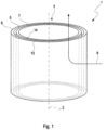
- FIG. 1 shows a cylindrical filter element 1, the filter element body 3 of which is made up of a support body 5 and structural bodies 6, 7.
- a corresponding, coaxially and concentrically positioned hollow-cylindrical structural body 6 , 7 is arranged both on the inner area 14 and on the outer area 13 of the support body 5 .
- the fluid flows 8 through the filter element 1 here, for example, from the outside of the hollow-cylindrical filter element 1 into the inner region of the hollow-cylindrical filter element 1 , after which the fluid is then passed on essentially parallel to the central axis 2 .
- filter elements 1 with structural bodies 6 and support bodies 5 in any geometric configuration can be used.
- Flat and/or cubic filter elements 1 are preferably used here.
- the outer structural body 6 is constructed as a spatially networked lattice structure 15 and is produced by means of a 3D printing process and is oriented essentially parallel to the support body 5 .
- the inner area 19 of the outer structural body 6 is partially in direct contact with the outer area 13 of the support body 5 and is firmly connected to the support body 5 in this contact area. This connection can take place by means of gluing the contact area or by a material connection method of the contact areas.
- Another possibility of connecting both bodies 5, 6 - not shown in the figures - is that the spatially networked lattice structure 15, which consists of rod elements 16, engages with the rod elements 16 through the structure of the support body 5 and in this way the connection of both bodies 5, 6 produces.
- the analogous consideration applies to the outer area 18 of the lattice structure 15 of the inner structural body 7 and the inner area 14 of the supporting body 5, which is in contact at least in certain areas.
- the spatial networking of the rod elements 16 through the cell structure 10 of the support body 5 for connecting the two bodies 5, 7 is possible, the cell structure 10 having a spatial honeycomb structure 11, but also having other shapes of any kind.
- the crosslinking and the mutual dimensionally stable connection of both bodies 6, 7 takes place through the penetration of the rod elements 16 of the lattice structure 15 through cells of the cell structure 10 of the support body 5, with the penetration on the support body 5 through the free space of the cell structure 10 or through the walls of the cell structure 10 , through.
- the supporting body 5 as a supporting body has to hold and support several lattice structures 15, for example, and also has to absorb the forces arising from the flowing fluid, the supporting body 5 is designed in a very stable form.
- the support body 5 has a honeycomb structure, namely the cell structure 10, which has a greater material strength and wall thickness 11 of the honeycomb structure 10 for the purpose of supporting forces.
- rod-shaped cell rods of the cell structure 10 have a larger cross section than the lattice rods 16 of the lattice structure 15. It is also possible that a filament material with higher strength is used when printing the support body 5 and/or during the 3D printing process the Cell structure 10 special, strength-enhancing material components are introduced into the melt of the filament.
- the choice of a possible cell structure 10, in this case a hexagonal honeycomb structure 10, supports the forces in a particularly favorable manner and at the same time generates sufficiently large and regular passages 12 for the fluid flowing through Fluid and the rod elements 16 running through these passages 12, which serve as connections between the support body 5 and the outer structural body 6, or as a connection of an inner structural body 7 with the outer structural body 6 through the support body 5.
- the rod elements 16 protruding through the passage openings 12 of the support body 5 can run directly through the passage opening 12 and/or penetrate areas of the honeycomb structure 10 and are thus firmly connected to it. This penetration of the rod elements 16 and the cell structure 10 additionally strengthens the connection.
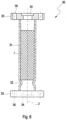
- a hollow-cylindrical structural body 6, 7 with a grid structure 15 made up of rod elements or grid rods 16 is 3 pictured.
- the rod elements 16 are here combined in a star and radial shape in a large number of such repeating arrangements and arranged in a chained manner.
- the hollow cylinder shown here shows this crosslinked structure in its longitudinal extension 21 and in its width 20, so that a spatially crosslinked, hollow-cylindrical structural body 6, 7 is formed.
- the star-shaped arranged rod elements 16 create free spaces which are arranged and oriented as meshes 17 or pores 17 in such a way that the fluid to be filtered can optimally flow through the structural body 6, 7. Impurities are retained in the meshes/pores 17 or on the rod elements 16, with the structural body 6, 7 being filled with impurities ensuring sufficient flow through 8 of the structural body 6, 7 for a long time due to the large number of meshes/pores 17, without that the increasing dynamic pressure when flowing through 8 of the structural body 6, 7 reaches critical values.
- the lattice structure 15 is arranged with an adhesive for connection to other coaxially one inside the other, preferably concentrically Structural bodies 6, 7 provided.
- This adhesive can, for example, have been positioned as an additional material with the filament during the printing process in these areas, with subsequent adhesive coating of this inner 14 and outer area 13 being possible.
- substances are introduced into the lattice structure 15 that accumulate in the meshes/pores 17 in order to generate special reactions and/or catalytic effects of the fluid to be filtered there .
- these can be suitable for certain contaminants to adhere permanently to the rod elements 16 and/or to join/chain substances present in the fluid to one another and thus to be able to be filtered out by the lattice structure 15 as contamination.
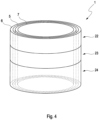
- a hollow-cylindrical filter element 1 made up of support body 5 and structural bodies 6, 7 with a plurality of sections 22, 23, 24 of different lattice structures 15 of the structural body 6, 7 is shown.
- the structural bodies 6, 7 are arranged coaxially, in particular concentrically, one within the other, with the supporting body 5 being positioned between the two structural bodies 6, 7.
- the structural bodies 6, 7 can be divided, for example, in their longitudinal extent 21 into a plurality of sections, in this case three sections 22, 23, 24. With these divisions, the sections 22, 23, 24 consist, for example, of different materials and/or the lattice structure 15 differs in terms of the number of rod elements 16 or the number of meshes/pores 17. It is thus possible for a coarse-meshed lattice structure 15 consisting of a few bar elements 16 to be shown in a first section 22 and for the section 23 adjoining this section 22 to have a finer lattice structure 15 with several shorter bar elements 16 than is present in section 22 .
- the transitions between the individual sections 22, 23, 24 and the different lattice structures 15 can be abruptly or continuously flowing.
- this sectional division of a structural body 6, 7 can be broken down into further concentrically arranged structural bodies 6, 7 and/or also into radial sections, not shown here.
- rough lattice structures 15 can follow on from less rough ones, and these can of course also have abrupt and/or continuous flowing transitions.
- the structural bodies 6, 7 consist of individual lattice structures 15 or of interconnected lattice structures 15 and thus of a plurality of connected structural elements 6, 7.
- sections 22, 23, 24, where the sections 22, 23, 24 can be dimensioned independently of one another and have different dimensions, is important for optimal filtering of the fluid.
- areas of the structural body 6, 7 through which the fluid flows less intensively can be optimally flowed through by the fluid by changing the dynamic pressure by means of larger or smaller meshes/pores 17 and fewer or more rod elements 16 and thereby filter the fluid efficiently.
- the figure 5 shows a hollow-cylindrical filter element 1 made up of supporting body 5 and structural bodies 6, 7, in which the structural bodies 6, 7 are arranged coaxially, preferably concentrically, with respect to one another.
- flow guidance elements 28, so-called guide bodies/flaps 28, are integrated into the lattice structures 15 of the structural bodies 6, 7.
- This guide body 28 are inside or outside the lattice structures 15 of the structural body 6, 7 printed during the 3D printing process.
- Such a guide body 28 positioned at the edge area of the grid body 15 can guide the fluid to be filtered specifically into or to certain areas of the grid body 15 due to its geometric shape and positioning, so that the previously described optimal flow 8 and filter effect of the filter element 1 is achieved.
- a possible effect here can be, for example, a circular turbulence of the fluid in the form or in the manner of a cyclone.
- the targeted guidance of the fluid can also be achieved by means of guide bodies 28 which are arranged inside the grid body 15 and are shaped accordingly.
- These inner guide bodies 28 are also introduced or printed directly into the lattice body 15 during the 3D printing of the latter.
- the guide bodies 28 can be arranged both within the lattice body 15 and between two or more lattice bodies 15 .
- the fluid flowing into a lattice body 15 can be guided very effectively and quickly into other lattice bodies 15 or distributed into them by the guide bodies 28 arranged across them.
- the fluid can also be directed in changing directions and thus into different filter areas by means of a plurality of guide bodies 28 assigned to one another.
- the guide bodies 28 are designed as flat, curved, winding, increasing or decreasing surfaces, with additional integral or molded portions being able to be present on or on the guide bodies 28 to support the guiding function of the fluid.
- solid geometric bodies for example in the shape of a cube, can also be introduced into the grid bodies 15 and the fluid can flow around them as a flow resistance. This creates turbulence which in turn influence the flow behavior of the fluid in such a way that it is directed specifically into certain areas of the filter element 1 and into the grid body 15 .
- a 3D-printed filter unit 30 with a housing 31, flanges 33 and a filter element 1 is shown.
- the outermost structural body 6 is not printed as a lattice body 15 but as a solid body in the form of a housing wall 31 .
- the housing 31 shown essentially corresponds to the geometric shape of the filter element 1 and is solidly constructed as this.
- the housing 31 can also be printed at the same time as the filter element 1 and as a one-piece component.
- Fastening flanges 33 are formed at the ends of the housing 31 and are used, for example, to mount the filter unit 30 on a machine.
- the flanges 33 are designed with fastening bores 35 for assembly using suitable fastening means and have corresponding inlet and outlet openings 34 for the inflow and outflow of the fluid. Both the fastening bores 35 and the inlet and outlet openings 34 are shaped accordingly during the 3D printing process.
- the housing 31 advantageously consists of a material with greater strength, which is produced during the printing process by means of appropriately suitable filaments. It is also conceivable that the filament used here is supplied with corresponding additional materials to increase its strength.
- a possible further embodiment is that the housing 31 as an independent component without a filter element 1 by means of a 3D printing process will be produced.
- the filter element 1 is inserted and positioned in the housing 31 at a later point in time.
- a stop 32 or an insertion limitation 32 can be formed in or on the housing 31 during the 3D printing process.
- the inserted filter element 1 can be fixed in the housing 31, in which case the flange 33 can also serve as a fixation from the insertion side.
- the fastening flanges 33 are attached to the housing 31 again, with one flange being designed so that it can be removed for mounting the filter element 1 .
- the previously produced filter element 1 can of course be pushed into a customary, existing housing 31, in which case instead of the housing 31 a suitable point in a pipeline can also be used. It is thus possible, for example, to be able to use such filter elements 1 at almost any point in a pipe system of a machine/motor.
- This removable flange 33 is subsequently reconnected to the housing 31 in a detachable or fixed manner by means of a suitable connection.
- the particular advantage of such a 3D-printed housing 31 of a filter unit 30 is that the shape and dimensions of the housing 31 can deviate from known symmetrical shapes, and complex housings 31 can be designed with frequently changing shapes.
- the filter elements 1 to be used here correspond to this housing shape. Especially with these filter elements 1 with multiple changing shapes, the figure 5 described guide body 28 of particular interest, so that all important areas of the filter element 1 can be effectively flowed through.
- the respective structural body 6, 7 and the supporting body 5 can be 3D-printed from different materials and/or material compositions be.
- the respective structural body 6, 7 and the supporting body 5 can each be 3D-printed from plastic and/or plastic material.
- the structure of the supporting body 5 has a cell structure 10 which has passages 12 formed by cells.
- the cells are formed with rod-shaped cell columns of the cell structure 10 .
- the meshes/pores 17 of the respective structural body 6, 7 are preferably smaller than the cells or the passages 12 of the support body 5.
- the cells or the passages 12 of the support body 5 can be at least twice, five times or ten times larger than the meshes/pores 17 of the respective structural body 6, 7.
- the lattice bars 16 of the lattice structure 15 of the respective structural body 6, 7 have a smaller cross section than cell bars of the cell structure 10 of the support body 5.
- the cross section of the cell bars of the cell structure 10 of the support body 5 can be at least twice or five times or ten times larger be than the cross section of the lattice bars 16 of the lattice structure 15 of the respective structural body 6, 7.
- a portion of the lattice bars 16 of the lattice structure 15 can enter or penetrate the openings 12 of the cell structure 10 .
- Part of the lattice rods 16 of the lattice structure 15 can preferably penetrate into the passages 12 of the cell structure 10 or penetrate them in such a way that the lattice structure 15 is fixed to the cell structure 10 in a form-fitting manner. A further additional fixation by fusible links can then be unnecessary.
- the filter element 1 can be designed as a ring filter element 40 in which the respective structural body 6, 7 and the support body 5 form a ring-shaped ring filter body 41.
- the filter element body 3 is ring-shaped and forms said ring filter body 41.
- the filter element 1 or the ring filter element 40 also has two end plates 42, 43, which are each arranged at an axial end of the ring filter body 41.
- the upper end disk 42 is designed as an open end disk and accordingly has a central passage opening 44 which is open towards an interior space 45 enclosed by the ring filter body 41 .
- Lower end plate 43 can also be configured as an open end plate.
- the lower end disk 43 can also be designed as a closed end disk, which closes the interior space 45 axially.
- At least one of the end plates 42, 43 can be printed onto the ring filter body 41 by means of 3D printing.
- FIG. 7 accordingly shows a ring filter element 40, in particular for a filter unit 30 for filtering a fluid, the ring filter element 40 being equipped with a ring-shaped ring filter body 41, which is formed by a filter element 1 of the type described above, and with two end plates 42, 43, each of which an axial end of the ring filter body 41 are arranged.
- the flow through the ring filter body 41 is radial.
- cleaned fluid can be discharged or uncleaned fluid can be supplied through the passage opening 44 .
- the axial direction of the ring filter element 40 is defined by its longitudinal central axis 46 .
Landscapes
- Chemical & Material Sciences (AREA)
- Chemical Kinetics & Catalysis (AREA)
- Engineering & Computer Science (AREA)
- Manufacturing & Machinery (AREA)
- Materials Engineering (AREA)
- Filtering Materials (AREA)
Description
Die vorliegende Erfindung betrifft ein Filterelement für eine Filtereinheit zum Filtern eines Fluids gemäß dem Oberbegriff des Anspruchs 1. Die Erfindung betrifft außerdem eine Filtereinheit mit einem derartigen Filterelement.The present invention relates to a filter element for a filter unit for filtering a fluid according to the preamble of
Zum Herausfiltern von festen Partikeln aus Flüssigkeiten kommen in entsprechenden Filtereinheiten Filterelemente zum Einsatz, die einen Filterkörper mit einem Filtermaterial zur Partikelfiltration besitzen. Diese Filtermaterialien weisen Filterstrukturen aus geeigneten Materialien auf. Beispielsweise werden Filterstrukturen aus Gewebe- und/oder Zellulosematerialien verwendet, welche materialbedingt eingeschränkte Filtereigenschaften aufweisen und nur bedingt in komplexe Formen gebracht werden können. Derartige Filterelemente weisen eine vorbestimmte und nicht veränderbare Filtercharakteristik auf, was eine Optimierung auf das zu filternde Fluid nur eingeschränkt zulässt.In order to filter out solid particles from liquids, filter elements are used in corresponding filter units, which have a filter body with a filter material for particle filtration. These filter materials have filter structures made of suitable materials. For example, filter structures made of fabric and/or cellulose materials are used, which have material-related limited filter properties and can only be brought into complex shapes to a limited extent. Such filter elements have a predetermined and unchangeable filter characteristic, which only allows limited optimization of the fluid to be filtered.
Aus der
Aus der
Das faserige dreidimensionale Gerüst setzt sich aus Strukturfasern verschiedener Abmessungen, insbesondere unterschiedlicher Faserdicken zusammen, welche alle die zuvor beschriebene Eigenschaft einer weiteren ersten Komponente aufweisen und durch die erwähnte thermische Behandlung miteinander verbunden sind. Das faserige dreidimensionale Gerüst von Verbundfasern besteht also aus unterschiedlich dimensionierten Strukturfasern, welche mehr oder weniger frei zueinander angeordnet und verbunden sind aber keine gleichmäßigen, sich wiederholende Strukturen aufweisen. Hierbei übernehmen die dickeren Strukturfasern eine Art Stützwirkung für die Filterstruktur, wobei die dünneren Strukturfasern die eigentliche, wesentliche Filterfunktion übernehmen. Dabei ist es möglich, dass sowohl die dickeren als auch die dünneren Strukturfasern aus dem gleichen Material bestehen. Zur Herstellung dieser Filterstruktur werden in ein Gerüst aus gröberen Strukturfasern feinere Strukturfasern beispielsweise durch Hydro-Verschlingungen oder durch Luft-Verschlingungen dispergiert. Alternativ kann ein feineres Gewebe aus thermoplastischen Strukturfasern gebildet werden um anschließend ein Gewebe mit gröberen Strukturfasern, zur Erreichung einer Filterstabilität einzubauen.The fibrous three-dimensional structure is composed of structural fibers of different dimensions, in particular different fiber thicknesses, which all have the previously described property of a further first component and are connected to one another by the thermal treatment mentioned. The fibrous three-dimensional framework of composite fibers consists of structural fibers of different dimensions, which are more or less freely arranged and connected to one another but do not have any regular, repeating structures. The thicker structural fibers take on a kind of supporting effect for the filter structure, with the thinner structural fibers taking on the actual, essential filter function. It is possible that both the thicker and the thinner structural fibers are made of the same material. To produce this filter structure, finer structural fibers are dispersed in a framework of coarser structural fibers, for example by hydro-interlacing or by air-interlacing. Alternatively, a finer fabric can be formed from thermoplastic structural fibers and then a fabric with coarser structural fibers can be installed to achieve filter stability.
Weiter entstehen durch die verbundenen Strukturfasern Hohlräume in denen funktionelle Teilchen zur Realisierung der Sorptionswirkung eingefangen sind, welche selber durch die thermoplastischen Verbundfasern und einer zweiten, niedrig schmelzenden Komponente gebildet werden. Somit werden bei der thermischen Verbindung der Strukturfasern nicht nur die unregelmäßige und freie Verbindung der Strukturfasern, sondern durch unterschiedlich aufschmelzende Komponenten funktionelle Einlagerungen in den Hohlräumen erzeugt. Ähnlich langkettigen Molekülen, können auf diese Weise sehr große faserige Gerüste, ähnlich einem Fließ, hergestellt werden. Zur Erzeugung besonderer Effekte können die Strukturfasern aus gekräuselten Fasern bestehen, die analog zu vorher beschriebenen Vorgehensweisen verarbeitet werden können. Dieser faserige Aufbau kann eine höhere Dichte aber auch eine hohe innere Beweglichkeit und somit Verformbarkeit des Gerüstes bewirken. Die bei der thermischen Behandlung entstehenden funktionalen Teilchen können beispielsweise aus Aktivkohle bestehen, wobei auch andere funktionale Teilchen wie beispielsweise Siliziumdioxid, Zeolith Ton, Aluminiumoxid und weitere erzeugt und eingelagert werden können.Furthermore, the connected structural fibers create cavities in which functional particles are captured for the realization of the sorption effect, which are themselves formed by the thermoplastic composite fibers and a second, low-melting component. Thus, when the structural fibers are thermally bonded, not only is the irregular and free connection of the structural fibers produced, but also functional inclusions in the cavities due to components that melt differently. Similar to long-chain molecules, very large fibrous structures, similar to a fleece. To create special effects, the structural fibers can consist of crimped fibers that can be processed analogously to the procedures described above. This fibrous structure can result in a higher density but also in a high internal mobility and thus deformability of the framework. The functional particles produced during the thermal treatment can consist of activated carbon, for example, while other functional particles such as silicon dioxide, zeolite clay, aluminum oxide and others can also be produced and stored.
Ein Verfahren zum Drucken eines Gewebekonstrukts mit eingebetteter Vaskulatur wird in der
Eine extrazelluläre Matrixzusammensetzung umgibt zumindest teilweise das eine oder die mehreren Gewebemuster und das Netzwerk von Gefäßkanälen. Bei dem hier verwendeten 3D-Druckverfahren können materialseitig gleiche sowie auch unterschiedliche Filamente verwendet werden, wobei diese Filamente beim 3D-Druckvorgang unter Verwendung spezieller Düsen gemischt werden können. Auch können Zusatzwerkstoffe wie Härter, Kleber usw. hierbei zugegeben werden. Teilweise sind besondere Zusatzwerkstoffe bereits als homogene Beimischungen oder als ständig verfügbare Beimischung innerhalb der Filamente eingebracht und bevorratet.An extracellular matrix composition at least partially surrounds the one or more tissue patterns and the network of vascular channels. With the 3D printing process used here, the same as well as different filaments can be used on the material side, whereby these filaments can be mixed during the 3D printing process using special nozzles. Additional materials such as hardeners, adhesives, etc. can also be added here. In some cases, special additional materials are already incorporated and stored as homogeneous admixtures or as constantly available admixtures within the filaments.
Ein gattungsgemäßes Filterelement ist aus der
Die vorliegende Erfindung beschäftigt sich mit dem Problem, für ein Filterelement zur Partikelfiltration eine verbesserte Ausführungsform anzugeben, die sich insbesondere durch eine hohe Robustheit und hohe Filterwirkung, sowie durch eine hohe Tiefenbeladungskapazität bei ausreichend Stabilität auszeichnet.The present invention deals with the problem of specifying an improved embodiment for a filter element for particle filtration, which is characterized in particular by a high degree of robustness and a high filter effect, as well as a high depth loading capacity with sufficient stability.
Dieses Problem wird erfindungsgemäß durch den Gegenstand des unabhängigen Anspruchs gelöst. Vorteilhafte Ausführungen sind Gegenstand der abhängigen Ansprüche.According to the invention, this problem is solved by the subject matter of the independent claim. Advantageous designs are the subject matter of the dependent claims.
Erfindungsgemäß wird hierfür eine Filterstruktur mittels einer räumlich vernetzten Gitterstruktur verwendet, welche vorzugsweise komplett durch ein 3D-Druckverfahren hergestellt wird. Bei diesem 3D-Druckverfahren werden Filamente geschmolzen und über Düsen schichtweise auf einen Träger aufgebracht bzw. entlang eines Trägers aufgebaut, wobei das gedruckte Filterelement aus verschiedenen Filamenten und verschiedenen Filament-Materialien bestehen kann. Hierbei kann das Filament, beispielsweise ein drahtförmiges endloses Material mit speziellen Zusätzen sein, wobei anstelle des drahtförmigen Filaments auch ein pulverförmiges, granulatartiges oder flüssiges Material zur Verarbeitung in den Druckdüsen verwendet werden kann. Dieses 3D-Druckverfahren ermöglicht es auch komplizierte Formen für das Filterelement herzustellen, bei dem unter anderen auch hinterschnittene Formen möglich sind. Ebenso kann dieses Filterelement sehr komplizierte aneinander gefügte Formen aufweisen, was eine maximale Nutzung des zur Verfügung stehenden Einbauraums für das Filterelement bedeutet.According to the invention, a filter structure is used for this purpose by means of a spatially networked lattice structure, which is preferably produced entirely by a 3D printing process. With this 3D printing process, filaments are melted and applied to a carrier in layers via nozzles or built up along a carrier, whereby the printed filter element can consist of different filaments and different filament materials. here the filament can be, for example, a wire-like endless material with special additives, it also being possible to use a powdery, granular or liquid material for processing in the printing nozzles instead of the wire-like filament. This 3D printing process also makes it possible to produce complicated shapes for the filter element, in which, among other things, undercut shapes are also possible. This filter element can also have very complicated shapes that are joined together, which means maximum use of the installation space available for the filter element.
Auch kann somit die Ausgestaltung der Filtereinheit unter optimaler Nutzung dem für die Filtereinheit zur Verfügung stehenden Bauraum erfolgen und bisher nicht herstellbare geometrische Ausführungen von Filtereinheiten ermöglichen.The configuration of the filter unit can thus also take place with optimal use of the installation space available for the filter unit and enable geometric configurations of filter units that could not previously be produced.
Entsprechend der Erfindung wird mittels dieses 3D-Druckverfahrens ein Stützkörper als Träger oder Traggerüst gedruckt, welches einen oder mehrere Strukturkörper, die als eigentliche Filter fungieren, stützen und somit dem gesamten Filterelement eine Formfestigkeit verleihen. Dieser Stützkörper kann an seiner äußeren sowie an seiner inneren Seite von wenigstens einem Strukturkörper kontaktiert werden, wobei die Strukturkörper, welche im Vergleich zum Stützkörper filigran und weniger formstabil ausgeführt sein können, durch den Kontakt zum Stützkörper, von diesem in ihrer Position und Form stabil gehalten werden.According to the invention, this 3D printing process is used to print a support body as a carrier or supporting frame, which supports one or more structural bodies that act as the actual filter and thus give the entire filter element dimensional stability. This support body can be contacted on its outer and on its inner side by at least one structural body, with the structural bodies, which can be made filigree and less dimensionally stable compared to the support body, being held stable in their position and shape by the contact with the support body become.
Die Strukturkörper und der Stützkörper können hierbei zweckmäßig jeweils zusammenhängend aus einem Stück gefertigt sein, wobei auch Ausführungen aus einzelnen Teilen zur späteren Verbauung möglich sind. Hierbei weisen die Strukturkörper eine räumlich vernetzte Gitterstruktur auf, die aus sich regelmäßig wiederholenden Anordnungen von Stabelementen bestehen. Die Stabelemente sind dabei so unter vorgegebenen räumlichen Winkeln angeordnet, dass die Gitterstruktur entsteht und sich ebenfalls räumlich wiederholend Freiräume, sogenannte Maschen/Poren bilden. Diese Maschen/Poren können speziell zur Filterung von flüssigen Fluiden Kantenlängen von 0,05 - 15 mm, insbesondere von 0,1 - 10 mm, aufweisen, wobei die tatsächlichen Kantenlängen und die dadurch bestimmten Maschen- und Porenabmessungen auf das zu filternde Fluid optimal abgestimmt sind. Hierbei wird besonderer Wert auf die Durchströmungsgeschwindigkeit des Fluids, sowie die entstehende Druckdifferenz vom in das Filterelement eintretenden bis zum austretenden Fluid geachtet, damit die Filterwirkung maximal und eine mögliche Erwärmung des durchströmenden Fluids gering gehalten wird. Bei der Filterung von gasförmigen Fluiden sind die Kantenlängen der Maschen/Poren vorzugsweise im Bereich 0,1 - 40 mm, insbesondere von 4 - 20 mm, ausgelegt. Durch die Wahl der auf das zu filternde Fluid abgestimmten Maschen- und Porengrößen können die mittels des 3D-Druckverfahrens hergestellten Filterelemente doppelte Filterflächen entgegen den heute gebräuchlichen Filtereinsätzen aufweisen.The structural body and the support body can expediently each be made in one piece, although designs made up of individual parts for later installation are also possible. In this case, the structural bodies have a spatially networked lattice structure, which consists of regularly repeating arrangements of rod elements. The bar elements are arranged at predetermined spatial angles in such a way that the lattice structure is created and spatially repeating free spaces, so-called meshes/pores, are also formed. Specifically for filtering liquid fluids, these meshes/pores can have edge lengths of 0.05-15 mm, in particular 0.1-10 mm, with the actual edge lengths and the mesh and pore dimensions determined thereby being optimally matched to the fluid to be filtered are. Particular attention is paid to the flow rate of the fluid and the resulting pressure difference between the fluid entering the filter element and the fluid exiting, so that the filter effect is kept to a maximum and possible heating of the fluid flowing through is kept to a minimum. When filtering gaseous fluids, the edge lengths of the meshes/pores are preferably in the range of 0.1-40 mm, in particular 4-20 mm. By choosing the mesh and pore sizes that are tailored to the fluid to be filtered, the ones produced using the 3D printing process can be used Filter elements have double filter surfaces in contrast to the filter inserts commonly used today.
Die beim 3D-Druckverfahren der Strukturkörper verwendeten Filamente können bei der Erzeugung der Gitterstrukturen in den Filamenten eingelagerte Zusatzwerkstoffe wie Stabilisatoren, Kleber aber auch katalytisch wirkende Materialen enthalten. Aus diesen speziellen eingelagerten Materialien können beim Drucken der Stabelemente beispielsweise die katalytisch wirkenden Materialen so ausgeschieden werden, dass sich diese in den Freiräumen der Maschen/Poren sammeln und dort ihre spezielle katalytische Funktion in Kontakt mit dem zu filternden Fluid ausführen können. Selbstverständlich sind auch weitere geeignete Verfahren wie beispielsweise ein Ausschmelzen bestimmter Materialen oder weitere zur Einbringung dieser in die Maschen/Poren möglich.The filaments used in the 3D printing process of the structural bodies can contain additional materials such as stabilizers, adhesives, but also catalytically active materials embedded in the filaments when creating the lattice structures. For example, the catalytically active materials can be excreted from these special embedded materials when the bar elements are printed in such a way that they collect in the free spaces of the meshes/pores and can perform their special catalytic function there in contact with the fluid to be filtered. Other suitable methods are of course also possible, such as melting out certain materials or others for introducing them into the meshes/pores.
Hierbei zeigen die zu filternden Fluide häufig eine koaleszierende Wirkung (hydrophob/oleophob) auf, bei der auszuscheidende/auszufilternde Anteile des Fluids und/oder Partikel als Verschmutzungsanteile zu größeren Partikeln/Tropfen zusammengeführt und geformt werden, welche dann durch die eigentliche Filterwirkung des Filterelements ausgeschieden werden.The fluids to be filtered often show a coalescing effect (hydrophobic/oleophobic), in which the parts of the fluid to be separated/filtered out and/or particles are brought together and formed as contamination parts into larger particles/droplets, which are then separated by the actual filtering effect of the filter element become.
Erfindungsgemäß sind der jeweilige Strukturkörper und der Stützkörper aus verschiedenen Materialien und/oder aus verschiedenen Materialzusammensetzungen 3D-gedruckt. Hierdurch lassen sich die Materialien an die unterschiedlichen Funktionen der beiden Komponenten anpassen, um die jeweilige Funktionalität zu verbessern.According to the invention, the respective structural body and the supporting body are 3D-printed from different materials and/or from different material compositions. This allows the materials to be adapted to the different functions of the two components in order to improve the respective functionality.
Zweckmäßig können der jeweilige Strukturkörper und der Stützkörper jeweils aus Kunststoff und/oder aus Kunststoffmaterial 3D-gedruckt sein. Hierbei lassen sich besonders feine Strukturen realisieren. Außerdem ist das Filterelement dadurch vergleichsweise preiswert.Expediently, the respective structural body and the support body can each be 3D-printed from plastic and/or from plastic material. Here you can realize particularly fine structures. In addition, the filter element is comparatively inexpensive as a result.
Vorteilhaft ist eine Ausführungsform, bei welcher die Struktur des Stützkörpers eine Zellenstruktur aufweist oder durch eine solche gebildet ist, wobei diese Zellenstruktur durch Zellen gebildete Durchlässe aufweist. Mit anderen Worten, die Zellen sind offen bzw. durchlässig ausgestaltet. Zusätzlich kann nun vorgesehen sein, dass die Maschen/Poren des jeweiligen Strukturkörper kleiner sind als die Zellen oder die Durchlässe des Stützkörpers. Hierdurch verbessern sich die Funktionalitäten von Strukturkörper und Stützkörper. Die kleineren Maschen/Poren verbessern die Filtrationswirkung. Die größeren Zellen erhöhen die Stabilität, insbesondere wenn damit eine vergrößerte Dicke der beteiligen Gitterstäbe einhergeht. Demnach kann insbesondere vorgesehen sein, dass Zellenstäbe zum Ausbilden der Zellenstruktur einen größeren Querschnitt aufweisen als Gitterstäbe zum Ausbilden der Gitterstruktur.An embodiment is advantageous in which the structure of the supporting body has a cell structure or is formed by such, this cell structure having passages formed by cells. In other words, the cells are designed to be open or permeable. In addition, it can now be provided that the meshes/pores of the respective structural body are smaller than the cells or the passages of the support body. This improves the functionalities of the structural body and support body. The smaller meshes/pores improve the filtration effect. The larger cells increase stability, especially when accompanied by an increased thickness of the grid bars involved. Accordingly, provision can be made in particular for cell bars for forming the cell structure to have a larger cross section than lattice bars for forming the lattice structure.
Gemäß einer Weiterbildung können die Zellen oder die Durchlässe des Stützkörpers mindestens zweimal oder fünfmal oder zehnmal größer sein als die Maschen/Poren des jeweiligen Strukturkörpers. Zusätzlich oder alternativ können die Zellenstäbe der Zellenstruktur einen zweimal oder fünfmal oder zehnmal größeren Querschnitt aufweisen als die Gitterstäbe der Gitterstruktur. Hierdurch lassen sich die Funktionalitäten von Strukturkörper und Stützkörper verbessern.According to a further development, the cells or the passages of the support body can be at least twice, five times or ten times larger than the meshes/pores of the respective structural body. Additionally or alternatively, the cell bars of the cell structure can have a cross section that is twice, five times, or ten times larger than the lattice bars of the lattice structure. This allows the functionalities of the structural body and support body to be improved.
Besonders vorteilhaft ist eine Ausgestaltung, bei welcher die Struktur des Stützkörpers eine Zellenstruktur aufweist, die durch Zellen gebildete Durchlässe aufweist, wobei ein Teil der Gitterstäbe der Gitterstruktur in die Durchlässe der Zellenstruktur eindringt oder diese durchdringt. Hierdurch wirken die Elemente der Gitterstruktur und der Zellenstruktur zusammen. Dies ermöglicht einerseits eine sehr kompakte Bauform, da sich Striukturkörper und Stützkörper mehr oder weniger durchdringen. Andererseits kann dadurch auch eine gewisse Fixierung des Strukturkörpers am Stützkörper realisiert werden, was dessen Stützwirkung verbessert.An embodiment is particularly advantageous in which the structure of the support body has a cell structure which has passages formed by cells, with part of the lattice bars of the lattice structure penetrating into the passages of the cell structure or penetrating through them. As a result, the elements of the lattice structure and the cell structure work together. On the one hand, this enables a very compact design, since the structural body and supporting body are more or less penetrate On the other hand, a certain fixation of the structural body on the supporting body can also be realized in this way, which improves its supporting effect.
Gemäß einer Weiterbildung kann vorgesehen sein, dass ein Teil der Gitterstäbe der Gitterstruktur in die Durchlässe der Zellenstruktur so eindringt oder diese so durchdringt, dass die Gitterstruktur formschlüssig an der Zellenstruktur festgelegt ist. Dabei kann insbesondere vorgesehen sein, dass die Gitterstäbe die Zellenstruktur nicht oder nur lose berühren. Somit bleiben die Gitterstäbe gegenüber der Zellenstruktur beweglich. Alternativ können an den Kontaktstellen je nach Druckverfahren auch Stoffschlussverbindungen, insbesondere Schmelzverbindungen, vorliegen. Durch den Formschluss lässt sich der jeweilige Strukturkörper einfach durch den Stützkörper stabilisieren.According to a further development, it can be provided that a part of the lattice bars of the lattice structure penetrates into the openings of the cell structure or penetrates them in such a way that the lattice structure is positively fixed to the cell structure. It can be provided in particular that the lattice bars do not touch the cell structure or touch it only loosely. The lattice bars thus remain movable in relation to the cell structure. Alternatively, depending on the printing process, material connections, in particular fusion connections, can also be present at the contact points. Due to the form fit, the respective structural body can be easily stabilized by the supporting body.
Wie bereits beschrieben können außerhalb und/oder innerhalb des Stützkörpers beispielsweise koaxial konzentrisch angeordnete Strukturkörper mit einer Gitterstruktur zur Anwendung kommen. Um die Formstabilität der Strukturkörper zu steigern können diese während des 3D-Druckverfahrens, durch in den Filamenten enthaltenen Kleber oder einen zusätzlich zugeführten Kleber, mit dem Stützkörper sowie auch mit weiteren Strukturkörpern verbunden werden. Auch bietet das 3D-Druckverfahren die Möglichkeit, verbindende Stabelemente untereinander zwischen dem Stützkörper und den Strukturkörpern, bzw. zwischen den einzelnen Strukturkörpern so zu platzieren, dass diese zumindest teilweise von diesen Stabelementen durchdrungen werden. Dadurch wird eine besonders hohe Festigkeit und Verbindung der Körper untereinander erreicht. Diese verbindenden Stabelemente können aus dem gleichen Material wie die Strukturkörper oder des Stützkörpers bestehen, wobei vorzugsweise zur Erhöhung der Festigkeit die verbindenden Stabelemente aus einem geeigneten Material höherer Festigkeit bestehen. Auch können diese verbindenden Stabelemente eine von der Gitterstruktur der Strukturkörper abweichende Form, Dicke und/oder geometrische Verbindungsstrukturen zu den Strukturkörpern aufweisen. So können am äußeren Bereich des Stützkörpers ein oder mehrere Strukturkörper angeordnet sein, bei denen die verbindenden Stabelemente sowohl innerhalb der Strukturkörper als auch auf den äußeren Bereichen der Strukturkörper verlaufen.As already described, structural bodies arranged coaxially concentrically and having a lattice structure can be used outside and/or inside the support body. In order to increase the dimensional stability of the structural bodies, they can be connected to the support body and also to other structural bodies during the 3D printing process using adhesive contained in the filaments or an additional adhesive. The 3D printing process also offers the possibility of placing connecting rod elements one below the other between the support body and the structural bodies, or between the individual structural bodies, in such a way that they are at least partially penetrated by these rod elements. As a result, a particularly high level of strength and connection between the bodies is achieved. These connecting bar elements can be made of the same material as the structural body or the support body, the connecting bar elements preferably being made of a suitable material of higher strength to increase the strength. Also, these connecting bar members can be one of the lattice structure the structural bodies have a different shape, thickness and/or geometric connection structures to the structural bodies. One or more structural bodies can be arranged on the outer area of the support body, in which case the connecting rod elements run both inside the structural body and on the outer areas of the structural body.
Eine weitere erfindungsgemäße Ausführungsform kann darin bestehen, dass die räumlich vernetzten Gitterstrukturen sprunghafte bzw. kontinuierliche Übergänge von verschieden großen Gitterstrukturen aufweisen und sich somit die Durchlässigkeit und die Filterfunktion verändern, bzw. angepasst werden können. Dies erfolgt beispielsweise in Abhängigkeit der Strömungsfunktion und/oder der Verteilung von zu filternden Partikelgrößen, was zu einer deutlichen Steigerung der Effektivität des Filterelements führt. Mit gleichem Änderungsverhalten kann auch eine sprunghafte und/oder kontinuierliche Veränderung des Materials der vernetzten Gitterstrukturen erfolgen. Diese zuvor beschriebenen Möglichkeiten der Veränderungen beziehen sich nicht nur auf die spezielle Verteilung der Gitterstrukturen und Materialen eines Strukturkörpers, sondern können auch bei benachbarten Strukturkörpern erfolgen, so dass mehrere äußere und/oder innere um einen Stützkörper angeordnete Strukturkörper eine Vielzahl von Veränderungen der Gitterstrukturen sowie der Materialen aufweisen können. All diese Veränderungen können selbstverständlich stufenlos fließend oder sprunghaft in Abschnitten erfolgen.A further embodiment according to the invention can consist in the fact that the spatially networked lattice structures have abrupt or continuous transitions from lattice structures of different sizes and the permeability and the filter function can thus change or be adapted. This takes place, for example, as a function of the flow function and/or the distribution of particle sizes to be filtered, which leads to a significant increase in the effectiveness of the filter element. A sudden and/or continuous change in the material of the crosslinked lattice structures can also take place with the same change behavior. The possibilities for changes described above not only relate to the special distribution of the lattice structures and materials of a structural body, but can also take place in neighboring structural bodies, so that several outer and/or inner structural bodies arranged around a support body result in a large number of changes to the lattice structures and the Materials may have. All of these changes can, of course, take place in a continuous, flowing manner or in jumps in sections.
Für alle diese Variationen ist es ebenfalls möglich, dass bei benachbarten beispielsweise im Wesentlichen parallel oder koaxial konzentrisch angeordneten Strukturkörpern bezüglich deren Kontaktbereiche ein fließender Verbindungsübergang mit sich ändernden Gitterstrukturen und/oder Materialen erfolgt. So steht beispielsweise ein außerhalb angeordneter Strukturkörper mit seinem inneren Bereich in direkten Kontakt mit dem äußeren Bereich eines innerhalb angeordneten Strukturkörpers. In diesem Bereich können die zuvor beschriebenen Verbindungen beider Strukturkörper erfolgen. Gleiches gilt analog für im inneren Bereich des Stützkörpers angeordnete Strukturkörper. Auch ist es möglich, dass die inneren und äußeren Strukturkörper inklusive der zuvor beschriebenen Veränderungen zusammen mit dem Stützkörper als ein einstückiges Bauteil ausgeführt sein können.For all of these variations, it is also possible that in the case of adjacent structural bodies arranged, for example, essentially parallel or coaxially concentrically, there is a smooth connection transition with changing lattice structures and/or materials with regard to their contact areas. For example, a structural body arranged outside has its inner area in direct contact with the outer area of one arranged inside structural body. The connections of both structural bodies described above can take place in this area. The same applies analogously to structural bodies arranged in the inner area of the support body. It is also possible that the inner and outer structural bodies, including the changes described above, can be designed together with the support body as a one-piece component.
Der Stützkörper übernimmt die Tragfunktion des gesamten Filterelements und ist daher besonders stabil ausgeführt. Hierzu ist es möglich, dass beim 3D-Druckverfahren des Stützkörpers ein Filament mit höherer Festigkeit verwendet wird. Weiter sind die Abmessungen und die Form des Stützkörpers an diese tragende Funktion durch stärker dimensionierte geometrische Ausführungen, insbesondere durch Zellenstrukturen angepasst. Bei der Formgebung des Stützkörpers können somit erfindungsgemäß Formen wie beispielsweise eine mehreckige Zellenstruktur, vorzugsweise als sechseckige Wabenstruktur mit deutlich verstärkter Wandstärke zum Einsatz kommen. Die verwendeten Gitterstrukturen können bedingt durch ihre Abmessungen und durch deren Maschendichte erhebliches Eigengewicht besitzen, was bei mehreren parallelen benachbarten Gitterstrukturen durch diese selber und deren Zusammenwirken nicht getragen werden könnten. Daher sind die Anforderungen an den Stützkörper entsprechend dieser Belastung auszulegen und zusätzlich an die wirkenden Kräfte des durchströmenden Fluids anzupassen, was über die Formgebung und die Dimensionierung des Stützkörpers und seiner Geometrie erfolgt. Der Stützkörper und die Strukturkörper können hierzu bereits gemeinsam verbunden und zusammen gedruckt werden. Einzeln gedruckte Stützkörper und Strukturkörper, welche anschließend zusammengefügt werden und dabei beispielsweise verklebt werden sind als weiteres Herstellverfahren möglich.The supporting body assumes the carrying function of the entire filter element and is therefore designed to be particularly stable. For this purpose, it is possible that a filament with higher strength is used in the 3D printing process of the support body. Furthermore, the dimensions and the shape of the supporting body are adapted to this supporting function through more heavily dimensioned geometric designs, in particular through cell structures. When shaping the support body, forms such as a polygonal cell structure, preferably a hexagonal honeycomb structure with a significantly increased wall thickness, can thus be used according to the invention. Due to their dimensions and their mesh density, the lattice structures used can have a considerable intrinsic weight, which, in the case of several parallel adjacent lattice structures, could not be borne by these themselves and their interaction. Therefore, the requirements for the support body must be designed according to this load and additionally adapted to the acting forces of the fluid flowing through, which is done via the shape and dimensioning of the support body and its geometry. For this purpose, the supporting body and the structural bodies can already be connected together and printed together. Individually printed supporting bodies and structural bodies, which are then joined together and, for example, glued in the process, are possible as a further manufacturing process.
Als weitere Ausführung können entsprechend der Erfindung Strömungsführungselemente, sogenannte Leitkörper oder Flaps zur Anwendung kommen. Das bei der Herstellung des Stützkörpers und der Strukturkörper angewandte 3D-Druckverfahren ermöglicht erstmals derartige Leitkörper sowohl an den äußeren Bereichen der Strukturkörper als auch innerhalb der Strukturkörper in beliebiger Anzahl und Form vorzusehen. Hierbei können die Leitkörper vielfältige geometrische Formen aufweisen, wobei diese aber immer die Aufgabe erfüllen, das Fluid in seiner Strömungsrichtung gezielt zu lenken. Ein solcher Leitkörper kann also schaufelförmig, stufenförmig oder als gewundene Fläche zum Einsatz kommen, wobei auch Ausführungen in Kubusform zur Erzeugung eines Strömungswiderstandes zur Verwirbelung des Fluids oder zur Veränderung des Staudrucks denkbar sind. Die Leitkörper können hierbei so innerhalb der Gitterstrukturen der Strukturkörper angeordnet sein, dass diese in beliebiger räumlicher Anordnung und Anzahl von den Stabelementen der Gitterstruktur durchdrungen werden können. Auch ist es beim gemeinsamen Drucken von Strukturköpern und/oder Stützkörper möglich, dass diese Leitkörper übergreifend durch mehrere Strukturkörper angeordnet und ausgeführt sind. Durch diese übergreifende Verbindung der Strukturkörper/Stützkörper wird eine zusätzliche Versteifung der gesamten gedruckten Filtereinheit erreicht. Auf diese Weise können auch Regionen der Filterelemente, welche bisher eine ungünstige Durchströmung aufzeigten und deren Filterwirkung eingeschränkt ist optimal zur Filterung des Fluids genutzt werden. Bei gleicher Abmessung des Filterelements weist dieses eine deutliche Steigerung der Filtereffektivität auf. Weiter ist es durch den Einsatz der Leitkörper zusätzlich möglich, durch die gezielte Lenkung des Fluids, das Fluid bei entsprechenden Verschmutzungen, einen vorbestimmten Bereich des Filterelements mit besonders geeigneten Filterwirkungen zuzuführen. Bei einer entsprechenden Anordnung der Leitkörper im Zuflussbereich des Filterelements, also vor dem Einströmen des Fluids in den Strukturkörper, kann durch die Leitkörper ein Zykloneffekt erzeugt werden, bei dem das Fluid vor dem Strukturkörper kreisförmig verwirbelt wird. Durch diesen Effekt können gröbere und schwerere Verschmutzungspartikel sich an der Gehäusewand sammeln, so dass diese erst gar nicht in den Filter eindringen können. Diese gröberen Verschmutzungspartikel werden entlang der Gehäusewand an eine geeignete Sammelstelle geleitet, wo diese auch entnommen werden können. Dieses vorherige Aussortieren möglicher gröberer Verschmutzungspartikel ermöglicht eine deutlich längere Einsatzzeit des Filterelements. Auf diese Art kann das Fluid also gezielt durch mehrere Abschnitte/Bereiche des Filters gelenkt und somit optimal gefiltert werden.As a further embodiment, flow guidance elements, so-called guide bodies or flaps, can be used according to the invention. The 3D printing process used in the production of the supporting body and the structural body makes it possible for the first time to provide such guide bodies in any number and shape both on the outer regions of the structural body and within the structural body. In this case, the guide bodies can have a variety of geometric shapes, but these always fulfill the task of directing the fluid in its flow direction in a targeted manner. Such a guide body can therefore be used in the form of a shovel, in steps or as a winding surface, although designs in the form of a cube are also conceivable for generating a flow resistance for turbulence of the fluid or for changing the dynamic pressure. The guide bodies can be arranged within the lattice structures of the structural bodies in such a way that they can be penetrated by the rod elements of the lattice structure in any spatial arrangement and number. When structural bodies and/or supporting bodies are printed together, it is also possible for these guide bodies to be arranged and designed to overlap multiple structural bodies. An additional stiffening of the entire printed filter unit is achieved by this overlapping connection of the structural body/support body. In this way, regions of the filter elements which previously had an unfavorable flow and whose filtering effect is limited can also be optimally used for filtering the fluid. With the same dimensions of the filter element, this shows a significant increase in filter effectiveness. Furthermore, it is additionally possible through the use of the guide body, through the targeted guidance of the fluid, to supply the fluid with corresponding contamination to a predetermined area of the filter element with particularly suitable filter effects. With a corresponding arrangement of the guide bodies in the inflow region of the filter element, ie before the fluid flows into the structural body, a cyclone effect can be generated by the guide bodies, in which the fluid is circular in front of the structural body gets swirled. This effect allows coarser and heavier dirt particles to collect on the housing wall, preventing them from penetrating the filter in the first place. These coarser dirt particles are guided along the housing wall to a suitable collection point, where they can also be removed. This previous sorting out of possible coarser contamination particles enables a significantly longer service life of the filter element. In this way, the fluid can be directed through several sections/areas of the filter and thus optimally filtered.
Gemäß einer vorteilhaften Anwendung kann das Filterelement als Ringfilterelement ausgestaltet sein, bei dem der jeweilige Strukturkörper und der Stützkörper einen ringförmigen Ringfilterkörper oder zumindest einen ringförmigen Teil davon bilden, wobei das Filterelement bzw. das Ringfilterelement außerdem zwei Endscheiben aufweist, die jeweils an einem axialen Ende des Ringfilterkörpers angeordnet sind.According to an advantageous application, the filter element can be designed as a ring filter element, in which the respective structural body and the support body form a ring-shaped ring filter body or at least a ring-shaped part thereof, with the filter element or the ring filter element also having two end disks, each of which is attached to an axial end of the Ring filter body are arranged.
Mit anderen Worten, ein erfindungsgemäßes Ringfilterelement weist einen ringförmigen Ringfilterkörper auf, der zumindest teilweise durch ein Filterelement der vorstehend beschriebenen Art gebildet ist. Demensprechend sind der jeweilige Strukturkörper und der Stützkörper ringförmig ausgestaltet, insbesondere zylindrisch. Das Ringfilterelement weist außerdem an den axialen Enden des Ringfilterkörpers jeweils eine Endscheibe auf. Vorzugsweise besteht der Ringfilterkörper ausschließlich aus dem ringförmig ausgestalteten Filterelement, da der ringförmige Filterelementkörper durch die Stützstruktur ausreichend Stabilität besitzt für bestimmte Anwendungen, bei denen beispielsweise geringe bis mittlere Differenzdrücke zwischen Rohseite und Reinseite auftreten. Bei anderen Anwendungen, bei denen beispielsweise hohe Differenzdrücke zwischen Roh- und Reinseite auftreten, kann der Ringfilterkörper zusätzlich mit einer Innenzarge und/oder mit einer Außenzarge ausgestattet sein, an der das ringförmige Filterelement bzw. dessen ringförmiger Filterelementkörper radial abgestützt ist.In other words, a ring filter element according to the invention has an annular ring filter body which is at least partially formed by a filter element of the type described above. Accordingly, the respective structural body and the supporting body are designed in the form of a ring, in particular cylindrical. The ring filter element also has an end disk on each of the axial ends of the ring filter body. The ring filter body preferably consists exclusively of the ring-shaped filter element, since the ring-shaped filter element body has sufficient stability due to the support structure for certain applications in which, for example, low to medium differential pressures occur between the raw side and the clean side. In other applications where, for example, high differential pressures between the raw and clean side occur, the ring filter body can also be provided with an inner frame and/or be equipped with an outer frame on which the annular filter element or its annular filter element body is radially supported.
Zweckmäßig kann nun zumindest eine der Endscheiben als offene Endscheibe ausgestaltet sein und eine zentrale Durchtrittsöffnung aufweisen. Die andere Endscheibe kann je nach Anwendungsform des Ringfilterelements ebenfalls als offene Endscheibe oder aber als geschlossene Endscheibe ausgestaltet sein, die einen vom Ringfilterkörper umschlossenen Innenraum axial verschließt. Zweckmäßig können die Endscheiben an den Ringfilterkörper mittels 3D-Druck angedruckt sein. Die Endscheiben können dabei aus einem anderen Material, insbesondere aus einem anderen Kunststoff bestehen als der jeweilige Strukturkörper und der Stützkörper. Ferner ist denkbar, die Endscheiben und den Stützkörper aus dem gleichen Material herzustellen.At least one of the end disks can now expediently be designed as an open end disk and have a central passage opening. Depending on the application of the ring filter element, the other end disk can also be configured as an open end disk or as a closed end disk that axially closes an interior space enclosed by the ring filter body. The end disks can expediently be printed onto the ring filter body by means of 3D printing. The end plates can be made of a different material, in particular a different plastic than the respective structural body and the support body. It is also conceivable to produce the end plates and the support body from the same material.
Eine erfindungsgemäße Ausführung ist als Weiterentwicklung in der Funktion einzelner Strukturkörper zu sehen. Hierbei kann beispielsweise der äußerste und/oder innerste Strukturkörper nicht mehr als Gitterstruktur ausgebildet sein, sondern als massiver Körper gedruckt werden und somit als Gehäusewand die geometrische Begrenzung der Filtereinheit selber darstellen. Da an ein Gehäuse höhere Festigkeitsanforderungen gestellt werden, kann beim gemeinsamen Strukturkörper und Gehäuse, oder einzelnen gedruckten Gehäuse ein hierzu geeignetes Material als Filament zur Anwendung kommen. Auch ist es denkbar, dass zur Erzielung dieser höheren Festigkeit besondere Materialen beim 3D-Drucken dem Filament im Moment des Druckens zusätzlich zugeführt werden.An embodiment according to the invention can be seen as a further development in the function of individual structural bodies. In this case, for example, the outermost and/or innermost structural body can no longer be designed as a lattice structure, but can be printed as a solid body and thus represent the geometric boundary of the filter unit itself as a housing wall. Since higher strength requirements are placed on a housing, a material suitable for this purpose can be used as a filament for the joint structural body and housing, or for individual printed housings. It is also conceivable that, in order to achieve this higher strength, special materials are additionally added to the filament during 3D printing at the moment of printing.
Innerhalb dieser Gehäusewand kann das Filterelement in gewohnter, zuvor beschriebener Anordnung ausgeführt sein, wobei zwischen der Gitterstruktur eines inneren Strukturkörpers und der Innenseite der gedruckten Gehäusewand eine feste Verbindung bestehen kann. Selbstverständlich kann die Gehäusewand von dem inneren benachbarten Strukturkörper losgelöst ausgeführt und gedruckt werden, wobei das eigentliche Filterelement dann nachträglich in das Gehäuse eingebracht und dort fixiert werden muss. Dies kann beispielsweise über Anschläge die als Einschubbegrenzung dienen erfolgen, wobei das Filterelement bis zu diesen Anschlägen eingeschoben wird und anschließend durch ein geeignetes Verfahren, beispielsweise eine Thermoschmelzverfahren oder einem Kleben mit dem Gehäuse lagefixiert fest verbunden wird. Selbstverständlich können auch wieder lösbare Befestigungsverfahren, wie beispielsweise Verschraubungen, Spannringe, Clipse oder weitere, eingesetzt werden.Within this housing wall, the filter element can be designed in the usual, previously described arrangement, with a fixed connection being able to exist between the lattice structure of an inner structural body and the inside of the printed housing wall. Of course, the housing wall of be designed and printed separately from the inner adjacent structural body, with the actual filter element then having to be subsequently introduced into the housing and fixed there. This can be done, for example, by means of stops that serve to limit the insertion, with the filter element being pushed in up to these stops and then fixed in position with the housing by a suitable method, for example a thermofusion method or gluing. Of course, detachable fastening methods such as screw connections, clamping rings, clips or others can also be used.
Das so gedruckte und mit einem Filterelement bestückte Gehäuse kann an seinen Enden, zur Erzeugung einer kompletten Filtereinheit, begrenzende Elemente in Formen von Befestigungsflanschen aufweisen. Bei diesen Befestigungsflanschen werden beim Drucken zeitgleich beispielsweise Befestigungsbohrungen sowie Ein- und Auslassöffnungen mit eingebracht. Um auch hier eine Austauschbarkeit des Filterelements zu ermöglich ist es denkbar, dass ein Befestigungsflansch lösbar mit dem Gehäuse verbunden ist. Somit kann das lose eingebrachte Filterelement ausgetauscht werden, während das Gehäuse wieder verwendet werden kann. Selbstverständlich ist auch ein kompletter Austausch der Filtereinheit möglich.The housing printed in this way and fitted with a filter element can have limiting elements in the form of fastening flanges at its ends in order to produce a complete filter unit. With these mounting flanges, for example, mounting holes and inlet and outlet openings are made at the same time during printing. In order to enable the filter element to be replaced here as well, it is conceivable for a fastening flange to be detachably connected to the housing. Thus, the loosely fitted filter element can be replaced while the housing can be reused. Of course, a complete replacement of the filter unit is also possible.
Bei der Variante der tauschbaren losen Filtereinheit können sowohl 3D-gedruckte Bauteile als auch heutige, standartmäßig hergestellten Bauteilen kombiniert verwendet werden.In the variant of the replaceable loose filter unit, both 3D-printed components and today's standard manufactured components can be used in combination.
Weitere wichtige Merkmale und Vorteile der Erfindung ergeben sich aus den Unteransprüchen, aus den Zeichnungen und aus der zugehörigen Figurenbeschreibung anhand der Zeichnungen.Further important features and advantages of the invention result from the subclaims, from the drawings and from the associated description of the figures based on the drawings.
Es versteht sich, dass die vorstehend genannten und die nachstehend noch zu erläuternden Merkmale nicht nur in der jeweils angegebenen Kombination, sondern auch in anderen Kombinationen oder in Alleinstellung verwendbar sind, ohne den Rahmen der vorliegenden Erfindung zu verlassen.It goes without saying that the features mentioned above and those still to be explained below can be used not only in the combination specified in each case, but also in other combinations or on their own, without departing from the scope of the present invention.
Bevorzugte Ausführungsbeispiele der Erfindung sind in den Zeichnungen dargestellt und werden in der nachfolgenden Beschreibung näher erläutert, wobei sich gleiche Bezugszeichen auf gleiche oder ähnliche oder funktional gleiche Komponenten beziehen.Preferred exemplary embodiments of the invention are illustrated in the drawings and are explained in more detail in the following description, with the same reference numbers referring to identical or similar or functionally identical components.
Es zeigen, jeweils schematisch
- Fig. 1
- ein hohlzylinderförmiges aus Stützkörper und Strukturkörpern auf-gebautes Filterelement,
- Fig. 2
- einen hohlzylinderförmigen Stützkörper mit Zellenstruktur,
- Fig. 3
- einen hohlzylinderförmigen Strukturkörper mit einer aus Stabelementen räumlich vernetzten Gitterstruktur,
- Fig. 4
- ein hohlzylinderförmiges aus Stützkörper und Strukturkörpern aufgebautes Filterelement mit mehreren Abschnitten unterschiedlicher Gitterstrukturen,
- Fig. 5
- ein hohlzylinderförmiges aus Stützkörper und Strukturkörpern aufgebautes Filterelement mit innerhalb und außerhalb der Gitterstruktur angeordneten Strömungsführungselementen/Leitkörpern,
- Fig. 6
- eine 3D-gedruckte Filtereinheit bestehend aus Gehäuse, Flanschen und Filterelement.
- 1
- a hollow-cylindrical filter element made up of support bodies and structural bodies,
- 2
- a hollow-cylindrical support body with a cell structure,
- 3
- a hollow-cylindrical structural body with a lattice structure spatially networked from rod elements,
- 4
- a hollow-cylindrical filter element made up of supporting bodies and structural bodies with several sections of different lattice structures,
- figure 5
- a hollow-cylindrical filter element made up of supporting bodies and structural bodies with flow guidance elements/guiding bodies arranged inside and outside the lattice structure,
- 6
- a 3D printed filter unit consisting of housing, flanges and filter element.
Der äußere Strukturkörper 6 ist als räumlich vernetzte Gitterstruktur 15 aufgebaut und wird mittels eines 3D-Druckverfahrens hergestellt und ist im Wesentlichen parallel zum Stützkörper 5 orientiert ausgerichtet. Der äußere Strukturkörper 6 steht mit seinem inneren Bereich 19 bereichsweise im direkten Kontakt mit dem äußeren Bereich 13 des Stützkörpers 5 und ist in diesem Kontaktbereich fest mit dem Stützkörper 5 verbunden. Diese Verbindung kann mittels einer Verklebung des Kontaktbereichs oder durch ein Stoffschlussverfahren der Kontaktbereiche erfolgen. Eine weitere Verbindungsmöglichkeit beider Körper 5, 6 -in den Figuren nicht dargestellt- besteht darin, dass die räumliche vernetzte Gitterstruktur 15, welche aus Stabelementen 16 besteht, mit den Stabelementen 16 durch die Struktur des Stützkörpers 5 greift und auf diese Weise die Verbindung beider Körper 5, 6 herstellt.The outer
Sowie der äußere Strukturkörper 6 mit seinem inneren Bereich 19 in Kontakt mit dem äußeren Bereich 13 des Stützkörpers 5 steht trifft die analoge Betrachtung auf den äußeren Bereich 18 der Gitterstruktur 15 des inneren Strukturkörpers 7 und dem wenigstens bereichsweise kontaktierten inneren Bereich 14 des Stützkörpers 5 zu. Ebenso ist die räumliche Vernetzung der Stabelemente 16 durch die Zellenstruktur 10 des Stützkörpers 5 zur Verbindung beider Körper 5, 7 möglich, wobei die Zellenstruktur 10 eine räumliche Wabenstruktur 11 aufweist, aber auch sonstige Formen jeglicher Art aufweisen kann.As soon as the
In der
Ein hohlzylinderförmiger Strukturkörper 6, 7 mit einer aus Stabelementen bzw. Gitterstäben 16 räumlich vernetzt aufgebauten Gitterstruktur 15 ist in
Durch die räumlich vernetzte Gitterstruktur 15 erzeugen die sternförmig angeordneten Stabelemente 16 Freiräume, welche als Maschen 17 oder Poren 17 so angeordnet und orientiert sind, dass das zu filternde Fluid optimal den Strukturkörper 6, 7 durchströmen kann. Verunreinigungen werden dabei in den Maschen/Poren 17, bzw. an den Stabelementen 16 zurückgehalten, wobei der sich mit Verunreinigungen füllende Strukturkörper 6, 7 durch die große Anzahl an Maschen/Poren 17 lange eine ausreichende Durchströmung 8 des Strukturkörpers 6, 7 gewährleistet, ohne das der ansteigende Staudruck beim Durchströmen 8 des Strukturkörpers 6, 7 kritische Werte erreicht. Am inneren 14 bzw. äußeren Bereich 13 des Strukturkörpers 6, 7 ist die Gitterstruktur 15 mit einem Kleber zur Verbindung mit weiteren koaxial ineinander, vorzugsweise konzentrisch angeordneten Strukturkörpern 6, 7 versehen. Dieser Kleber kann beispielsweise als Zusatzwerkstoff mit dem Filament beim Druckvorgang in diesen Bereichen positioniert worden sein, wobei auch eine nachträgliche Kleberbeschichtung dieses inneren 14 und äußeren Bereichs 13 möglich ist. Ebenso ist es möglich, dass beim 3D-Druckverfahren mit den Filamenten oder als zusätzlich zugeführtes Material Stoffe in die Gitterstruktur 15 eingebracht werden, die sich konzentriert in den Maschen/Poren 17 ansammeln um dort spezielle Reaktionen und/oder katalytische Wirkungen des zu filternden Fluids erzeugen. Diese können unter anderem dazu geeignet sein, dass bestimmte Verunreinigungen dauerhaft an den Stabelementen 16 anhaften und/oder im Fluid vorhandene Stoffe aneinander fügen/ketten und diese somit durch die Gitterstruktur 15 als Verunreinigung herausgefiltert werden können.Due to the spatially
In
Die Strukturkörper 6, 7 können beispielsweise in ihrer Längserstreckung 21 in mehrere Abschnitte, hier in drei Abschnitte 22, 23, 24, aufgeteilt sein. Bei diesen Aufteilungen bestehen die Abschnitte 22, 23, 24 beispielsweise aus unterschiedlichen Materialien und/oder ist die Gitterstruktur 15 in ihre Anzahl der ausgeführten Stabelemente 16 oder der Anzahl der Maschen/Poren 17 unterschiedlich. So ist es möglich, dass in einem ersten Abschnitt 22 eine grobmaschige, aus wenigen Stabelementen 16 bestehende Gitterstruktur 15, abgebildet ist und der an diesen Abschnitt 22 angrenzenden Abschnitt 23 eine feinere Gitterstruktur 15, mit mehreren kürzeren Stabelementen 16, als im Abschnitt 22 vorhanden aufweist.The
Analog kann der darauf folgende Abschnitt 24 über eine weitere, deutlich unterscheidende Gitterstruktur 15 verfügen.Analogously, the following
Die Übergänge zwischen den einzelnen Abschnitten 22, 23, 24 und den unterschiedlichen Gitterstrukturen 15 können hierbei sprungartig oder kontinuierlich fließend erfolgen. Diese abschnittsweise Aufteilung eines Strukturkörpers 6, 7 kann, wie zuvor erwähnt, in weiteren konzentrisch angeordneten Strukturkörpern 6, 7 und/oder auch in radiale Abschnitte hier nicht abgebildet aufgegliedert sein. Auch hier können grobe auf weniger grobe Gitterstrukturen 15 folgen und diese können selbstverständlich auch sprunghafte und/oder kontinuierliche fließende Übergänge aufweisen. Dabei ist es unerheblich, ob die Strukturkörper 6, 7 als einzelne Gitterstrukturen 15 oder aus zusammen verbundenen Gitterstrukturen 15 und somit aus mehreren verbundenen Strukturelementen 6, 7 bestehen.The transitions between the
Die Aufteilung in unterschiedliche Abschnitte 22, 23, 24, wobei die Abschnitte 22, 23, 24 unabhängig voneinander und unterschiedlich in ihren Abmessungen dimensioniert sein können, ist für eine optimale Filterung des Fluids wichtig. So können beispielsweise Bereiche des Strukturkörpers 6, 7 welche weniger intensiv vom Fluid durchströmt werden, durch eine Veränderung des Staudrucks mittels größeren oder kleinerer Maschen/Poren 17 und weniger oder mehreren Stabelementen 16 optimal vom Fluid durchströmt werden und dadurch effizient das Fluid filtern.The division into
Die
Ein solcher, am Randbereich des Gitterkörpers 15 positionierter Leitkörper 28 kann das zu filternde Fluid durch seine geometrische Formgebung und Positionierung gezielt in oder an bestimmte Bereiche des Gitterkörpers 15 leiten, so dass die zuvor beschriebene optimale Durchströmung 8 und Filterwirkung des Filterelements 1 erreicht wird. Ein hierbei möglicher Effekt kann beispielsweise ein kreisförmiges, Verwirbeln des Fluids in Form bzw. nach Art eines Zyklons darstellen. Beim Durströmen 8 der Strukturkörper 6, 7 kann das gezielte Lenken des Fluids auch durch innerhalb der Gitterkörpers 15 angeordnete und entsprechend geformten Leitkörpern 28 erzielt werden. Auch diese inneren Leitkörper 28 werden direkt beim 3D-Drucken des Gitterkörpers 15 mit in diese eingebracht bzw. gedruckt.Such a
Weiter können die Leitkörper 28 sowohl innerhalb des Gitterkörpers 15 als auch zwischen zwei oder mehreren Gitterkörpern 15 angeordnet sein. Somit kann das in einem Gitterkörper 15 einströmende Fluid durch die übergreifenden angeordneten Leitkörper 28 sehr effektiv und schnell in weitere Gitterkörper 15 geleitet, bzw. in diese verteilt werden. Auch können durch mehrere einander zugeordnete Leitkörper 28 das Fluid in wechselnde Richtungen und somit in unterschiedliche Filterbereiche gelenkt werden. Hierzu sind die Leitkörper 28 als flächig gebogene, gewundene, sich vergrößernde oder verkleinernde Flächen ausgelegt, wobei auf oder an den Leitkörpern 28 zusätzliche An- oder Ausformungen zur Unterstützung der Leitfunktion des Fluids vorhanden sein können.Furthermore, the
Anstelle der flächigen Leitkörper 28 können auch geometrische massive Körper, beispielsweise in Kubusform, in die Gitterkörper 15 eingebracht werden und als Strömungswiderstand vom Fluid umflossen werden. Hierbei entstehen Verwirbelungen die wiederum das Strömungsverhalten des Fluids so beeinflussen, dass dieses dadurch gezielt in bestimmte Bereiche des Filterelements 1 und in die Gitterkörper 15 gelenkt wird.Instead of the
In
Eine mögliche weitere Ausführungsform besteht darin, dass das Gehäuse 31 als eigenständiges Bauteil ohne ein Filterelement 1 mittels eines 3D-Druckverfahren hergestellt wird. Dabei wird das Filterelement 1 zu einem späteren Zeitpunkt in das Gehäuse 31 eingebracht und positioniert.A possible further embodiment is that the
Zur Positionierung kann, während des 3D-Druckvorgangs, ein Anschlag 32 bzw. eine Einschubbegrenzung 32 in oder an dem Gehäuse 31 ausgeformt werden. Das eingeschobene Filterelement 1 kann im Gehäuse 31 fixiert werden, wobei hier auch der Flansch 33 von der Einschubseite aus als Fixierung dienen kann. Die Befestigungsflansche 33 sind auch hier wieder am Gehäuse 31 angebracht, wobei ein Flansch zur Montage des Filterelements 1 demontierbar ausgeführt ist. Anstelle des gedruckten Gehäuses 31 kann das vorher hergestellte Filterelement 1 selbstverständlich in ein gebräuchliches, vorhandenes Gehäuse 31 eingeschoben werden, wobei statt dem Gehäuse 31 auch eine geeignete Stelle in einer Rohrleitung verwendet werden kann. Somit ist es beispielsweise möglich, solche Filterelemente 1 an beinahe beliebiger Stelle eines Rohrsystems einer Maschine/Motor verwenden zu können.For positioning, a
Dieser demontierbare Flansch 33 wird nachträglich mit dem Gehäuse 31 mittels einer geeigneten Verbindung wieder lösbar oder fest verbunden. Der besondere Vorteil für ein derartig, 3D-gedrucktes Gehäuse 31 einer Filtereinheit 30 besteht darin, dass das Gehäuse 31 in seiner Form und Abmessungen von bekannten symmetrischen Formen abweichen kann und komplexe Gehäuse 31, mit sich häufig ändernden Formverläufen, ausgeführt werden können. Die hierbei zu verwendenden Filterelemente 1 entsprechen korrespondierend dieser Gehäuseform. Speziell bei diesen Filterelementen 1 mit mehrfach ändernden Formen sind die in
Grundsätzlich können der jeweilige Strukturkörper 6, 7 und der Stützkörper 5 aus verschiedenen Materialien und/oder Materialzusammensetzungen 3D-gedruckt sein. Dabei können der jeweilige Strukturkörper 6, 7 und der Stützkörper 5 jeweils aus Kunststoff und/oder Kunststoffmaterial 3D-gedruckt sein.In principle, the respective
Bevorzugt ist eine Ausgestaltung, bei der die Struktur des Stützkörpers 5 eine Zellenstruktur 10 aufweist, die durch Zellen gebildete Durchlässe 12 aufweist. Dabei sind die Zellen mit stangenförmigen Zellenstäben der Zellenstruktur 10 gebildet. Vorzugsweise sind die Maschen/Poren 17 des jeweiligen Strukturkörper 6, 7 kleiner als die Zellen oder die Durchlässe 12 des Stützkörpers 5. Beispielsweise können die Zellen oder die Durchlässe 12 des Stützkörpers 5 mindestens zweimal oder fünfmal oder zehnmal größer sein als die Maschen/Poren 17 des jeweiligen Strukturkörper 6, 7.An embodiment is preferred in which the structure of the supporting
Ferner kann vorgesehen sein, dass die Gitterstäbe 16 der Gitterstruktur 15 des jeweiligen Strukturkörpers 6, 7 einen kleineren Querschnitt aufweisen als Zellenstäbe der Zellenstruktur 10 des Stützkörpers 5. Beispielsweise kann der Querschnitt der Zellenstäbe der Zellenstruktur 10 des Stützkörpers 5 mindestens zweimal oder fünfmal oder zehnmal größer sein als der Querschnitt der Gitterstäbe 16 der Gitterstruktur 15 des jeweiligen Strukturkörpers 6, 7.Furthermore, it can be provided that the lattice bars 16 of the
Wie weiter oben erläutert kann ein Teil der Gitterstäbe 16 der Gitterstruktur 15 in die Durchlässe 12 der Zellenstruktur 10 eindringen oder diese durchdringen. Bevorzugt kann ein Teil der Gitterstäbe 16 der Gitterstruktur 15 in die Durchlässe 12 der Zellenstruktur 10 so eindringen oder diese so durchdringen, dass die Gitterstruktur 15 formschlüssig an der Zellenstruktur 10 festgelegt ist. Eine weitere zusätzliche Fixierung durch Schmelzverbindungen kann dann entbehrlich sein.As explained above, a portion of the lattice bars 16 of the
Gemäß
Claims (15)
- Filter element (1) for a filter unit (30) for filtering a fluid,- wherein the filter element (1) has a filter element body (3), through which fluid can flow, having at least one structural body (6, 7) and one support body (5),- wherein the respective structural body (6, 7) has a filter structure permeable to the fluid with a plurality of apertures/pores (17),- wherein the filter structure is configured as a spatially cross-linked lattice structure (15) and the spatially cross-linked lattice structure (15) has a repeating regularity,- wherein the apertures/pores (17) are formed as free spaces by lattice rods (16) connected securely to one another,- wherein the support body (5) has a support structure permeable to the fluid,- wherein the respective structural body (6, 7) and the support body (5) are produced respectively by means of a 3D-printing method,characterised in that
the respective structural body (6, 7) and the support body (5) are 3D-printed from different materials and/or material compositions. - Filter element (1) according to claim 1,
characterised in that
the respective structural body (6, 7) and the support body (5) are 3D-printed respectively from plastic and/or plastic material. - Filter element (1) according to any one of the preceding claims,
characterised in that- the structure of the support body (5) has a cell structure (10) which has passages (12) formed by cells, wherein the apertures/pores (17) of the respective structural body (6, 7) are smaller than the cells or the passages (12) of the support body (5) and/or- the structure of the support body (5) has a cell structure (10) which has passages (12) formed by cells, wherein lattice rods (16) of the lattice structure (15) of the respective structural body (6, 7) have a smaller cross-section than cell rods of the cell structure of the support body (5). - Filter element (1) according to claim 3,
characterised in that- the cells or the passages (12) of the support body (5) are at least twice or five times or ten times larger than the apertures/pores (17) of the respective structural body (6, 7), and/or- the cross-section of the cell rods of the cell structure of the support body (5) are at least twice or five times or ten times larger than the cross-section of the lattice rods (16) of the lattice structure (15) of the respective structural body (6, 7). - Filter element (1) according to any one of the preceding claims,
characterised in that- the structure of the support body (5) has a cell structure (10) which has passages (12) formed by cells,- a portion of the lattice rods (16) of the lattice structure (15) penetrate into or pass through the passages (12) of the cell structure (10). - Filter element (1) according to claim 5,
characterised in that
a portion of the lattice rods (16) of the lattice structure (15) penetrate into or pass through the passages (12) of the cell structure (10) in such a way that the lattice structure (15) is fixed to the cell structure (10) in a form-fitting manner. - Filter element according to any one of claims 3 to 6,
characterised in that- only one structural body (6, 7) is provided, wherein the cell structure of the support body (5) is arranged inside the lattice structure (15) of this structural body (6, 7), wherein some of the lattice rods (16) penetrate through the cells, or- two structural bodies (6, 7) arranged coaxially inside one another are provided and the support body (5) is arranged between the two structural bodies (6, 7), wherein some of the lattice rods (16) penetrate the cells of the cell structure (10) of the support body (5) and connect the two structural bodies (6, 7) to one another. - Filter element (1) according to any one of the preceding claims,
characterised in that- the respective structural body (6, 7) and the support body (5) are configured to be in the form of hollow cylinders and are arranged coaxially inside one another, preferably concentrically to one another, wherein the respective structural body (6, 7) and the support body (5) are arranged at least approximately parallel to one another, and/or- the respective structural body (6, 7) is securely connected to the support body (5), wherein the secure connection between the respective structural bodies (6, 7) and the support body (5) is formed by a material connection. - Filter element (1) according to any one of the preceding claims,
characterised in that- further structural bodies (6, 7) are provided on two structural bodies (6, 7) arranged coaxially inside one another,- a further structural body (6), with its inner region (19), is in direct contact with the outer region (18) of the structural body (7) and is securely connected thereto,- a further structural body (7), with its outer region (18), is in direct contact with the inner region (19) of the structural body (7) and is securely connected thereto,- it can be provided in particular that the structural bodies (6, 7) penetrate one another via their outer regions (18) and inner regions (19) in an overlapping manner at least in some areas. - Filter element (1) according to any one of the preceding claims
characterised in that- materials/substances which are reactive or have a catalytic effect on the fluid are embedded in the apertures/pores (17) formed by the cross-linked and securely connected lattice rods (16), wherein the fluid to be filtered has a coalescing effect for forming particles which can be separated, and/or- the apertures/pores (17) of the support body (5) for filtering liquid fluids, formed by the connected lattice rods (16), each have edge lengths of 0.05 mm to 15 mm, preferably 0.1 mm to 10 mm, or for filtering gaseous fluids each have edge lengths of 0.1 mm to 40 mm, preferably 4 mm to 20 mm. - Filter element (1) according to any one of the preceding claims,
characterised in that- a plurality of adjacent structural bodies (6, 7) have mutually different cross-linked lattice structures (15),- a plurality of adjacent structural bodies (6, 7) have material properties of the cross-linked lattice structures (15) which differ from one another,- the mutually different cross-linked lattice structures (15) and the mutually different material properties of the cross-linked lattice structures (15) change abruptly or continuously,- in particular it can be provided that the respective structural body (6, 7) and the support body (5) can be made in one piece. - Filter element (1) according to any one of the preceding claims,
characterised in that- flow guide elements/guide bodies (28) are formed on and/or inside the structural bodies (6, 7) and the support body (5).- the flow guide elements/guide bodies (28) are configured to overlap on further structural bodies (6, 7) and or the support body (5),- the flow guide elements/guide bodies (28) have a flat and/or curved and/or sinuous shape,- the flow guide elements/guide bodies (28) change their shape abruptly or continuously. - Filter element (1) according to any one of the preceding claims,
characterised in that- the filter element (1) is configured as a ring filter element (40), in which the respective structural body (6, 7) and the support body (5) form an annular ring filter body (41) or at least an annular part thereof,- the filter element (1) also has two end discs (42, 43), which are arranged respectively at an axial end of the ring filter body (41). - Ring filter element (40) for a filter unit (30) for filtering a fluid,- with an annular ring filter body (41), which has a filter element (1) according to any one of the preceding claims or is formed thereby,- with two end discs (42, 43), each of which is arranged at one axial end of the ring filter body (41).
- Filter unit (30) with a housing (31) and with a filter element (1) inserted into the housing (31) according to one or more of the preceding claims.
Applications Claiming Priority (2)
| Application Number | Priority Date | Filing Date | Title |
|---|---|---|---|
| DE102019207003.5A DE102019207003B4 (en) | 2019-05-14 | 2019-05-14 | Filter element for a filter unit and filter unit |
| PCT/EP2020/057785 WO2020229026A1 (en) | 2019-05-14 | 2020-03-20 | Filter element for a filter unit |
Publications (3)
| Publication Number | Publication Date |
|---|---|
| EP3969147A1 EP3969147A1 (en) | 2022-03-23 |
| EP3969147B1 true EP3969147B1 (en) | 2023-06-14 |
| EP3969147C0 EP3969147C0 (en) | 2023-06-14 |
Family
ID=70008476
Family Applications (1)
| Application Number | Title | Priority Date | Filing Date |
|---|---|---|---|
| EP20714508.7A Active EP3969147B1 (en) | 2019-05-14 | 2020-03-20 | Filter element for a filter unit |
Country Status (6)
| Country | Link |
|---|---|
| US (1) | US20220143533A1 (en) |
| EP (1) | EP3969147B1 (en) |
| CN (1) | CN113825552A (en) |
| DE (1) | DE102019207003B4 (en) |
| PL (1) | PL3969147T3 (en) |
| WO (1) | WO2020229026A1 (en) |
Family Cites Families (17)
| Publication number | Priority date | Publication date | Assignee | Title |
|---|---|---|---|---|
| FI900719A0 (en) * | 1989-08-24 | 1990-02-14 | Albany Int Corp | FILTER. |
| CN2068414U (en) * | 1990-06-08 | 1991-01-02 | 双鸭山矿务局选煤厂 | Metal vane of filter |
| US5662728A (en) | 1992-12-31 | 1997-09-02 | Hoechst Celanese Corporation | Particulate filter structure |
| CN100368054C (en) * | 2003-06-10 | 2008-02-13 | 揖斐电株式会社 | Honeycomb structural body |
| DE102009023951B3 (en) * | 2009-06-04 | 2011-01-05 | Mann + Hummel Gmbh | Filter device for liquid filtration |
| DE102010051756B4 (en) * | 2010-11-17 | 2021-01-21 | Robert Bosch Gmbh | Filter insert |
| US10532303B2 (en) * | 2013-03-15 | 2020-01-14 | Pyrotek Incorporated | Ceramic filters |
| US10117968B2 (en) | 2013-11-05 | 2018-11-06 | President And Fellows Of Harvard College | Method of printing a tissue construct with embedded vasculature |
| CN105041529A (en) * | 2015-06-24 | 2015-11-11 | 广东信达雅三维科技有限公司 | Filter and laser printing manufacturing method and application thereof |
| CN206214865U (en) * | 2016-06-30 | 2017-06-06 | 中天储能科技有限公司 | A kind of filter core of lithium battery slurries filtration |
| KR101875838B1 (en) * | 2016-09-08 | 2018-07-06 | 전남대학교산학협력단 | Oil vapor filter by using three-dimensional celluar structure and air cleaning device provided with the same |
| DE202016105013U1 (en) * | 2016-09-09 | 2016-09-23 | Nordson Corporation | Filter candle for separating impurities from a plastic melt |
| US10359128B2 (en) * | 2016-10-21 | 2019-07-23 | Emerson Process Management Regulator Technologies, Inc. | Lattice control cage for a regulator |
| WO2018122985A1 (en) * | 2016-12-27 | 2018-07-05 | 武藤工業株式会社 | Filter and method for manufacturing same, and classifier |
| US10413852B2 (en) * | 2017-03-29 | 2019-09-17 | Pall Corporation | Filter, filter device, and method of use |
| DE202017104240U1 (en) * | 2017-07-17 | 2017-08-03 | Ask Chemicals L.P. | Precursor for a ceramic filter and ceramic filter |
| CN108568160A (en) * | 2018-04-04 | 2018-09-25 | 华南理工大学 | A kind of high-temperature nickel-base alloy multistage filter and manufacturing method |
-
2019
- 2019-05-14 DE DE102019207003.5A patent/DE102019207003B4/en active Active
-
2020
- 2020-03-20 EP EP20714508.7A patent/EP3969147B1/en active Active
- 2020-03-20 CN CN202080036243.4A patent/CN113825552A/en active Pending
- 2020-03-20 US US17/611,043 patent/US20220143533A1/en not_active Abandoned
- 2020-03-20 WO PCT/EP2020/057785 patent/WO2020229026A1/en active Search and Examination
- 2020-03-20 PL PL20714508.7T patent/PL3969147T3/en unknown
Also Published As
| Publication number | Publication date |
|---|---|
| WO2020229026A1 (en) | 2020-11-19 |
| EP3969147C0 (en) | 2023-06-14 |
| DE102019207003B4 (en) | 2022-07-07 |
| US20220143533A1 (en) | 2022-05-12 |
| EP3969147A1 (en) | 2022-03-23 |
| DE102019207003A1 (en) | 2020-11-19 |
| PL3969147T3 (en) | 2023-12-27 |
| CN113825552A (en) | 2021-12-21 |
Similar Documents
| Publication | Publication Date | Title |
|---|---|---|
| EP3064262B1 (en) | Filter medium, method for producing a filter medium and filter element with a filter medium | |
| DE60021055T2 (en) | FOLDED FILTER ELEMENT AND METHOD FOR PRODUCING A FOLDED FILTER ELEMENT | |
| DE69906109T2 (en) | FILTER AND METHOD FOR FILTRATING A FLUID | |
| DE69029455T2 (en) | Filter system | |
| DE2645634A1 (en) | PIPE FILTER FLOWED FROM THE INSIDE OUT AND THE PROCESS FOR ITS MANUFACTURING | |
| WO2002000326A2 (en) | Particle trap and method for separating particles from the flow of a liquid | |
| EP2543420B1 (en) | Porous ceramic filter | |
| DE102011009325B4 (en) | Method and molding device for producing a filter element | |
| EP2978550A1 (en) | Slm filter system | |
| EP0540546B1 (en) | Filter for thermoplastic material | |
| EP3969147B1 (en) | Filter element for a filter unit | |
| WO2019020442A1 (en) | Liquid filter and tank filter system having a liquid filter | |
| DE69935432T2 (en) | FILTER ELEMENT AND METHOD FOR THE PRODUCTION THEREOF | |
| DE10116408C1 (en) | Device for filtering a liquid, in particular for filtering a polymer plastic melt | |
| EP2059378B1 (en) | Device for filtering a thermoplastic polymer melt | |
| DE9318673U1 (en) | Hollow cylindrical filter element and filter unit made with it | |
| DE602004006611T2 (en) | Strainer basket for filtering fiber suspensions and process for its preparation | |
| EP4234207A1 (en) | Filter unit for an extruder, filter assembly and corresponding filter changing device, and method of manufacturing such a filter unit | |
| DE102013018199B4 (en) | Liquid filter, in particular for fuel | |
| DE19922326A1 (en) | Filter medium for filtering gases has a pre-deposition layer on crude side of support layer and main deposition layer on pure side of support layer | |
| EP2892629B1 (en) | Filter element | |
| WO2012085052A1 (en) | Filter element | |
| WO1998005410A1 (en) | Filter with an open-pore element made of sintered material | |
| DE2322386A1 (en) | Disposable filter cartridge prodn - by winding non woven fibre material on perforated core and compressing with open meshed strands | |
| WO2007014602A2 (en) | Filter element and a device |
Legal Events
| Date | Code | Title | Description |
|---|---|---|---|
| STAA | Information on the status of an ep patent application or granted ep patent |
Free format text: STATUS: UNKNOWN |
|
| STAA | Information on the status of an ep patent application or granted ep patent |
Free format text: STATUS: THE INTERNATIONAL PUBLICATION HAS BEEN MADE |
|
| PUAI | Public reference made under article 153(3) epc to a published international application that has entered the european phase |
Free format text: ORIGINAL CODE: 0009012 |
|
| STAA | Information on the status of an ep patent application or granted ep patent |
Free format text: STATUS: REQUEST FOR EXAMINATION WAS MADE |
|
| 17P | Request for examination filed |
Effective date: 20211129 |
|
| AK | Designated contracting states |
Kind code of ref document: A1 Designated state(s): AL AT BE BG CH CY CZ DE DK EE ES FI FR GB GR HR HU IE IS IT LI LT LU LV MC MK MT NL NO PL PT RO RS SE SI SK SM TR |
|
| DAV | Request for validation of the european patent (deleted) | ||
| DAX | Request for extension of the european patent (deleted) | ||
| GRAP | Despatch of communication of intention to grant a patent |
Free format text: ORIGINAL CODE: EPIDOSNIGR1 |
|
| STAA | Information on the status of an ep patent application or granted ep patent |
Free format text: STATUS: GRANT OF PATENT IS INTENDED |
|
| INTG | Intention to grant announced |
Effective date: 20230210 |
|
| GRAS | Grant fee paid |
Free format text: ORIGINAL CODE: EPIDOSNIGR3 |
|
| GRAA | (expected) grant |
Free format text: ORIGINAL CODE: 0009210 |
|
| STAA | Information on the status of an ep patent application or granted ep patent |
Free format text: STATUS: THE PATENT HAS BEEN GRANTED |
|
| AK | Designated contracting states |
Kind code of ref document: B1 Designated state(s): AL AT BE BG CH CY CZ DE DK EE ES FI FR GB GR HR HU IE IS IT LI LT LU LV MC MK MT NL NO PL PT RO RS SE SI SK SM TR |
|
| REG | Reference to a national code |
Ref country code: CH Ref legal event code: EP |
|
| REG | Reference to a national code |
Ref country code: DE Ref legal event code: R096 Ref document number: 502020003789 Country of ref document: DE |
|
| REG | Reference to a national code |
Ref country code: AT Ref legal event code: REF Ref document number: 1578810 Country of ref document: AT Kind code of ref document: T Effective date: 20230715 |
|
| U01 | Request for unitary effect filed |
Effective date: 20230711 |
|
| U07 | Unitary effect registered |
Designated state(s): AT BE BG DE DK EE FI FR IT LT LU LV MT NL PT SE SI Effective date: 20230720 |
|
| REG | Reference to a national code |
Ref country code: LT Ref legal event code: MG9D |
|
| PG25 | Lapsed in a contracting state [announced via postgrant information from national office to epo] |
Ref country code: NO Free format text: LAPSE BECAUSE OF FAILURE TO SUBMIT A TRANSLATION OF THE DESCRIPTION OR TO PAY THE FEE WITHIN THE PRESCRIBED TIME-LIMIT Effective date: 20230914 Ref country code: ES Free format text: LAPSE BECAUSE OF FAILURE TO SUBMIT A TRANSLATION OF THE DESCRIPTION OR TO PAY THE FEE WITHIN THE PRESCRIBED TIME-LIMIT Effective date: 20230614 |
|
| PG25 | Lapsed in a contracting state [announced via postgrant information from national office to epo] |
Ref country code: RS Free format text: LAPSE BECAUSE OF FAILURE TO SUBMIT A TRANSLATION OF THE DESCRIPTION OR TO PAY THE FEE WITHIN THE PRESCRIBED TIME-LIMIT Effective date: 20230614 Ref country code: HR Free format text: LAPSE BECAUSE OF FAILURE TO SUBMIT A TRANSLATION OF THE DESCRIPTION OR TO PAY THE FEE WITHIN THE PRESCRIBED TIME-LIMIT Effective date: 20230614 Ref country code: GR Free format text: LAPSE BECAUSE OF FAILURE TO SUBMIT A TRANSLATION OF THE DESCRIPTION OR TO PAY THE FEE WITHIN THE PRESCRIBED TIME-LIMIT Effective date: 20230915 |
|
| PG25 | Lapsed in a contracting state [announced via postgrant information from national office to epo] |
Ref country code: SK Free format text: LAPSE BECAUSE OF FAILURE TO SUBMIT A TRANSLATION OF THE DESCRIPTION OR TO PAY THE FEE WITHIN THE PRESCRIBED TIME-LIMIT Effective date: 20230614 |
|
| PG25 | Lapsed in a contracting state [announced via postgrant information from national office to epo] |
Ref country code: IS Free format text: LAPSE BECAUSE OF FAILURE TO SUBMIT A TRANSLATION OF THE DESCRIPTION OR TO PAY THE FEE WITHIN THE PRESCRIBED TIME-LIMIT Effective date: 20231014 |
|
| PG25 | Lapsed in a contracting state [announced via postgrant information from national office to epo] |
Ref country code: SM Free format text: LAPSE BECAUSE OF FAILURE TO SUBMIT A TRANSLATION OF THE DESCRIPTION OR TO PAY THE FEE WITHIN THE PRESCRIBED TIME-LIMIT Effective date: 20230614 Ref country code: SK Free format text: LAPSE BECAUSE OF FAILURE TO SUBMIT A TRANSLATION OF THE DESCRIPTION OR TO PAY THE FEE WITHIN THE PRESCRIBED TIME-LIMIT Effective date: 20230614 Ref country code: RO Free format text: LAPSE BECAUSE OF FAILURE TO SUBMIT A TRANSLATION OF THE DESCRIPTION OR TO PAY THE FEE WITHIN THE PRESCRIBED TIME-LIMIT Effective date: 20230614 Ref country code: IS Free format text: LAPSE BECAUSE OF FAILURE TO SUBMIT A TRANSLATION OF THE DESCRIPTION OR TO PAY THE FEE WITHIN THE PRESCRIBED TIME-LIMIT Effective date: 20231014 Ref country code: CZ Free format text: LAPSE BECAUSE OF FAILURE TO SUBMIT A TRANSLATION OF THE DESCRIPTION OR TO PAY THE FEE WITHIN THE PRESCRIBED TIME-LIMIT Effective date: 20230614 |
|
| REG | Reference to a national code |
Ref country code: DE Ref legal event code: R097 Ref document number: 502020003789 Country of ref document: DE |
|
| PLBE | No opposition filed within time limit |
Free format text: ORIGINAL CODE: 0009261 |
|
| STAA | Information on the status of an ep patent application or granted ep patent |
Free format text: STATUS: NO OPPOSITION FILED WITHIN TIME LIMIT |
|
| U20 | Renewal fee paid [unitary effect] |
Year of fee payment: 5 Effective date: 20240326 |
|
| 26N | No opposition filed |
Effective date: 20240315 |
|
| PGFP | Annual fee paid to national office [announced via postgrant information from national office to epo] |
Ref country code: PL Payment date: 20240312 Year of fee payment: 5 |
|
| PGFP | Annual fee paid to national office [announced via postgrant information from national office to epo] |
Ref country code: CH Payment date: 20240401 Year of fee payment: 5 |