EP3968423A1 - Secondary battery and method for manufacturing same - Google Patents
Secondary battery and method for manufacturing same Download PDFInfo
- Publication number
- EP3968423A1 EP3968423A1 EP20836539.5A EP20836539A EP3968423A1 EP 3968423 A1 EP3968423 A1 EP 3968423A1 EP 20836539 A EP20836539 A EP 20836539A EP 3968423 A1 EP3968423 A1 EP 3968423A1
- Authority
- EP
- European Patent Office
- Prior art keywords
- electrode
- coating
- electrode tab
- portions
- display
- Prior art date
- Legal status (The legal status is an assumption and is not a legal conclusion. Google has not performed a legal analysis and makes no representation as to the accuracy of the status listed.)
- Pending
Links
Images







Classifications
-
- H—ELECTRICITY
- H01—ELECTRIC ELEMENTS
- H01M—PROCESSES OR MEANS, e.g. BATTERIES, FOR THE DIRECT CONVERSION OF CHEMICAL ENERGY INTO ELECTRICAL ENERGY
- H01M4/00—Electrodes
- H01M4/02—Electrodes composed of, or comprising, active material
- H01M4/04—Processes of manufacture in general
- H01M4/0402—Methods of deposition of the material
- H01M4/0404—Methods of deposition of the material by coating on electrode collectors
-
- H—ELECTRICITY
- H01—ELECTRIC ELEMENTS
- H01M—PROCESSES OR MEANS, e.g. BATTERIES, FOR THE DIRECT CONVERSION OF CHEMICAL ENERGY INTO ELECTRICAL ENERGY
- H01M50/00—Constructional details or processes of manufacture of the non-active parts of electrochemical cells other than fuel cells, e.g. hybrid cells
- H01M50/50—Current conducting connections for cells or batteries
- H01M50/531—Electrode connections inside a battery casing
- H01M50/54—Connection of several leads or tabs of plate-like electrode stacks, e.g. electrode pole straps or bridges
-
- H—ELECTRICITY
- H01—ELECTRIC ELEMENTS
- H01M—PROCESSES OR MEANS, e.g. BATTERIES, FOR THE DIRECT CONVERSION OF CHEMICAL ENERGY INTO ELECTRICAL ENERGY
- H01M10/00—Secondary cells; Manufacture thereof
- H01M10/04—Construction or manufacture in general
- H01M10/0413—Large-sized flat cells or batteries for motive or stationary systems with plate-like electrodes
-
- H—ELECTRICITY
- H01—ELECTRIC ELEMENTS
- H01M—PROCESSES OR MEANS, e.g. BATTERIES, FOR THE DIRECT CONVERSION OF CHEMICAL ENERGY INTO ELECTRICAL ENERGY
- H01M10/00—Secondary cells; Manufacture thereof
- H01M10/05—Accumulators with non-aqueous electrolyte
- H01M10/058—Construction or manufacture
- H01M10/0585—Construction or manufacture of accumulators having only flat construction elements, i.e. flat positive electrodes, flat negative electrodes and flat separators
-
- H—ELECTRICITY
- H01—ELECTRIC ELEMENTS
- H01M—PROCESSES OR MEANS, e.g. BATTERIES, FOR THE DIRECT CONVERSION OF CHEMICAL ENERGY INTO ELECTRICAL ENERGY
- H01M10/00—Secondary cells; Manufacture thereof
- H01M10/04—Construction or manufacture in general
-
- H—ELECTRICITY
- H01—ELECTRIC ELEMENTS
- H01M—PROCESSES OR MEANS, e.g. BATTERIES, FOR THE DIRECT CONVERSION OF CHEMICAL ENERGY INTO ELECTRICAL ENERGY
- H01M10/00—Secondary cells; Manufacture thereof
- H01M10/04—Construction or manufacture in general
- H01M10/0436—Small-sized flat cells or batteries for portable equipment
-
- H—ELECTRICITY
- H01—ELECTRIC ELEMENTS
- H01M—PROCESSES OR MEANS, e.g. BATTERIES, FOR THE DIRECT CONVERSION OF CHEMICAL ENERGY INTO ELECTRICAL ENERGY
- H01M10/00—Secondary cells; Manufacture thereof
- H01M10/04—Construction or manufacture in general
- H01M10/0463—Cells or batteries with horizontal or inclined electrodes
-
- H—ELECTRICITY
- H01—ELECTRIC ELEMENTS
- H01M—PROCESSES OR MEANS, e.g. BATTERIES, FOR THE DIRECT CONVERSION OF CHEMICAL ENERGY INTO ELECTRICAL ENERGY
- H01M10/00—Secondary cells; Manufacture thereof
- H01M10/04—Construction or manufacture in general
- H01M10/049—Processes for forming or storing electrodes in the battery container
-
- H—ELECTRICITY
- H01—ELECTRIC ELEMENTS
- H01M—PROCESSES OR MEANS, e.g. BATTERIES, FOR THE DIRECT CONVERSION OF CHEMICAL ENERGY INTO ELECTRICAL ENERGY
- H01M4/00—Electrodes
- H01M4/02—Electrodes composed of, or comprising, active material
- H01M4/04—Processes of manufacture in general
-
- H—ELECTRICITY
- H01—ELECTRIC ELEMENTS
- H01M—PROCESSES OR MEANS, e.g. BATTERIES, FOR THE DIRECT CONVERSION OF CHEMICAL ENERGY INTO ELECTRICAL ENERGY
- H01M50/00—Constructional details or processes of manufacture of the non-active parts of electrochemical cells other than fuel cells, e.g. hybrid cells
- H01M50/10—Primary casings; Jackets or wrappings
- H01M50/102—Primary casings; Jackets or wrappings characterised by their shape or physical structure
- H01M50/105—Pouches or flexible bags
-
- H—ELECTRICITY
- H01—ELECTRIC ELEMENTS
- H01M—PROCESSES OR MEANS, e.g. BATTERIES, FOR THE DIRECT CONVERSION OF CHEMICAL ENERGY INTO ELECTRICAL ENERGY
- H01M50/00—Constructional details or processes of manufacture of the non-active parts of electrochemical cells other than fuel cells, e.g. hybrid cells
- H01M50/50—Current conducting connections for cells or batteries
- H01M50/531—Electrode connections inside a battery casing
-
- H—ELECTRICITY
- H01—ELECTRIC ELEMENTS
- H01M—PROCESSES OR MEANS, e.g. BATTERIES, FOR THE DIRECT CONVERSION OF CHEMICAL ENERGY INTO ELECTRICAL ENERGY
- H01M50/00—Constructional details or processes of manufacture of the non-active parts of electrochemical cells other than fuel cells, e.g. hybrid cells
- H01M50/50—Current conducting connections for cells or batteries
- H01M50/543—Terminals
- H01M50/552—Terminals characterised by their shape
- H01M50/553—Terminals adapted for prismatic, pouch or rectangular cells
- H01M50/557—Plate-shaped terminals
-
- Y—GENERAL TAGGING OF NEW TECHNOLOGICAL DEVELOPMENTS; GENERAL TAGGING OF CROSS-SECTIONAL TECHNOLOGIES SPANNING OVER SEVERAL SECTIONS OF THE IPC; TECHNICAL SUBJECTS COVERED BY FORMER USPC CROSS-REFERENCE ART COLLECTIONS [XRACs] AND DIGESTS
- Y02—TECHNOLOGIES OR APPLICATIONS FOR MITIGATION OR ADAPTATION AGAINST CLIMATE CHANGE
- Y02E—REDUCTION OF GREENHOUSE GAS [GHG] EMISSIONS, RELATED TO ENERGY GENERATION, TRANSMISSION OR DISTRIBUTION
- Y02E60/00—Enabling technologies; Technologies with a potential or indirect contribution to GHG emissions mitigation
- Y02E60/10—Energy storage using batteries
-
- Y—GENERAL TAGGING OF NEW TECHNOLOGICAL DEVELOPMENTS; GENERAL TAGGING OF CROSS-SECTIONAL TECHNOLOGIES SPANNING OVER SEVERAL SECTIONS OF THE IPC; TECHNICAL SUBJECTS COVERED BY FORMER USPC CROSS-REFERENCE ART COLLECTIONS [XRACs] AND DIGESTS
- Y02—TECHNOLOGIES OR APPLICATIONS FOR MITIGATION OR ADAPTATION AGAINST CLIMATE CHANGE
- Y02P—CLIMATE CHANGE MITIGATION TECHNOLOGIES IN THE PRODUCTION OR PROCESSING OF GOODS
- Y02P70/00—Climate change mitigation technologies in the production process for final industrial or consumer products
- Y02P70/50—Manufacturing or production processes characterised by the final manufactured product
Definitions
- the present invention relates to a secondary battery and a method for manufacturing the same, and more particularly, to a secondary battery, in which a notching step is removed to simplify processes, and a method for manufacturing the same.
- secondary batteries refer to chargeable and dischargeable batteries, unlike primary batteries that are not chargeable.
- the secondary batteries are being widely used in the high-tech electronic fields such as mobile phones, notebook computers, and camcorders.
- the secondary battery comprises an electrode assembly in which electrodes and separators are alternately stacked and a case accommodating the electrode assembly.
- a method for manufacturing the secondary battery having the above-described above structure comprises a step of manufacturing an electrode, a step of manufacturing an electrode assembly, and a step of accommodating the electrode assembly in a case.
- the method for manufacturing the secondary battery comprises a notching process for forming a tab in the step of manufacturing the electrode.
- the method for manufacturing the secondary battery according to the present invention has a problem in which a lot of time is taken to manufacture the electrode due to the notching process, and particularly, many defects occur due to burrs and delamination that occur during the notching process.
- the present invention is invented to solve the above problems, and an object of the present invention is to provide a secondary battery, in which a notching process of processing an electrode tab is removed to simplify processes, thereby significantly reducing a time taken to manufacture the secondary battery, and particularly, significantly reducing a defect rate by preventing burrs and delamination that occur during the notching process, and a method for manufacturing the secondary battery.
- a method for manufacturing a secondary battery according to the present invention for achieving the above object comprises: an electrode preparation step (S10) of preparing electrodes, each of which is provided with a coating portion coated with an electrode active material and a non-coating portion that is not coated with the electrode active material; an electrode assembly manufacturing step (S20) of alternately stacking the electrodes and separators to manufacture an electrode assembly, wherein the electrodes are stacked so that the non-coating portions overlap each other; a non-coating portion bonding step (S30) of bonding the overlapping non-coating portions to each other; a display part formation step (S40) of forming a display part for setting a cutting point on a surface of the bonded non-coating portion; and an electrode tab manufacturing step (S50) of cutting the bonded non-coating portion with respect to the display part to manufacture an electrode tab.
- the display part formation process (S40) may comprise: a photographing process of photographing the surface of the overlapping non-coating portions; an inspection process of inspecting whether the photographed image of the non-coating portions is within a set range of a previously input image of the non-coating portions; and a display process of forming a display part for setting the cutting point on the surface of the overlapping non-coating portions when the image of the non-coating portions, which is photographed in the inspection process, is within the set range of the previously input image of the non-coating portions.
- a display part for setting the cutting point may be formed on each of both vertex portions on the surface of the overlapping non-coating portions, and in the electrode tab manufacturing step (S50), both the vertex portions of the overlapping non-coating portions may be cut to be inclined with respect to the display part to manufacture the electrode tab.
- the display part may be formed as a display hole passing from a top surface to a bottom surface of the overlapping non-coating portions.
- Each of the non-coating portions may comprise a connection surface connected to the coating portion and a bonding surface extending from the connection surface
- the overlapping non-coating portions may be bonded to each other through the bonding surface
- the bonding surface may be divided into an uncut part connected to the connection surface and a cut part extending from the uncut part
- the display part for setting the cutting point may be formed on each of both vertex portions of the cut part
- both the vertex portions of the cut part may be cut to be inclined with respect to the display part to manufacture the electrode tab.
- the display hole may be formed to be inclined in both the vertex portions of the overlapping non-coating portions, and in the electrode tab manufacturing step (S50), both the vertex portions of the non-coating portions may be cut to be inclined along the display hole defined in the non-coating portion.
- the non-coating portions in addition to all the display part may be cut to be inclined so that the display parts do not remain on the electrode tab.
- the method may further comprise, after the electrode tab manufacturing step (S50), a display part inspection step (S60) of inspecting whether the display parts remain on the electrode tab, wherein, in the display part inspection step (S60), the electrode tab is photographed, and a photographed image of the electrode and a previously input image are compared with each other to inspect whether the display parts remain on the electrode tab.
- the method may further comprise, after the display part inspection step (S60), an uncut part reinforcement step (S65) of bonding the uncut part of the bonding surface again to reinforce bonding force of the uncut part.
- the method may further comprise, after the uncut part reinforcement step (S65), a tape attachment step (S67) of attaching a protective tape on the uncut part to protect the uncut part.
- the method may further comprise, after the tape attachment step (S67),; an electrode lead coupling step (S70) of coupling an electrode lead to the electrode tab; and a pouch accommodation step (S80) of accommodating the electrode assembly, to which the electrode lead is coupled, in a pouch to complete the secondary battery.
- a secondary battery manufactured by the method for manufacturing the secondary battery comprises: an electrode assembly in which electrodes, each of which is provided with a coating portion coated with an electrode active material and an electrode tab that is not coated with the electrode active material, and separators are alternately stacked, wherein the electrodes are stacked so that the electrode tabs overlap each other, wherein the overlapping electrode tabs comprise a connection surface connected to the coating portion and a bonding surface extending from the connection surface, and the bonding surface comprises an uncut part connected to the connection surface and a cut part which extends from the uncut part and of which both vertex portions are provided as inclined surfaces.
- the method for manufacturing the secondary battery according to the present invention may comprise the electrode preparation step, the electrode assembly manufacturing step, the non-coating portion bonding step, the display part formation step, and the electrode tab manufacturing step. Due to these features, the notching process for forming the electrode tab when the electrode is manufactured may be omitted to increase in simplification of the process, and particularly, the non-coating portion may be cut with respect to the display part to obtain the cutting accuracy and the uniform cutting force, thereby continuously manufacturing the electrode assembly having the uniform quality.
- the display part formation step may comprise the photographing process, the inspection process, and the display process. Due to these features, the display part may be disposed at the same position on the surface of the non-coating portion to obtain the cutting accuracy and the uniform cutting force.
- the display part may be formed on both the vertex portions of the non-coating portion with respect to the display part may be cut to be inclined. Due to this feature, the area of the electrode tab may be maximally secured.
- the uncut part of the bonding surface of the bonded non-coating portion may be provided. Due to this feature, the bonding force of the portion of the binding surface connected to the connection surface of the non-coating portion may be stably secured.
- the display part may be cut when the electrode tab is manufactured. Due to this feature, the display part may not remain on the electrode tab, and thus, the damage due to the display part remaining on the electrode tab may be previously prevented.
- the uncut part may be bonded again. Due to this feature, the bonding force of the uncut part may be reinforced. That is, when cutting the cut portion, the bonding force of the uncut part may be weakened. Accordingly, the uncut part may be bonded again to reinforce the bonding force of the uncut part.
- the protective tape may be attached to the uncut part. Due to this feature, the bonding force of the uncut part may be prevented from being weakened by the external impact.
- a secondary battery according to a first embodiment of the present invention comprises an electrode assembly 100, an electrode lead 200 coupled to the electrode assembly 100, and a pouch 300 accommodating the electrode assembly 100 in a state in which a front end of the electrode lead 200 is pulled out to the outside.
- the electrode assembly 100 has a structure in which a plurality of electrodes and a plurality of separators are alternately stacked.
- Each of the electrodes comprises a coating portion coated with an electrode active material and an electrode tab that is a non-coating portion that is not coated with the electrode active material.
- the electrodes are stacked so that the electrode tabs overlap each other.
- a plurality of electrodes comprise a first electrode 110 and a second electrode 120.
- the separator 130 is disposed between the first electrode 110 and the second electrode 120.
- the first electrode 110 and the second electrode 120 are alternately stacked in the state in which the separator 130 is disposed therebetween.
- the first electrode 110 comprises a first coating portion coated with a first electrode active material and a first electrode tab 112 that is a non-coating portion that is not coated with the first electrode active material.
- the second electrode 120 comprises a second coating portion 121 coated with a second electrode active material and a second electrode tab that is a non-coating portion that is not coated with the second electrode active material.
- the first electrode tab 112 and the second electrode tab 122 are disposed to be pulled out toward both sides of the electrode assembly 100, respectively.
- first electrode tab 112 is disposed to be pulled out toward one end (a left end of the electrode assembly when viewed in FIG. 2 ) of the electrode assembly 100
- second electrode tab 122 is disposed to be pulled out toward the other end (a right end of the electrode assembly when viewed in FIG. 2 ) of the electrode assembly 100.
- the overlapping electrode tabs comprise a connection surface connected to the coating portion and a bonding surface extending from the connection surface, and the bonding surface comprises an uncut part connected to the connection surface and a cut part which extends from the uncut part and of which both vertex portions are provided as inclined surfaces.
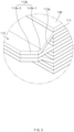
- the overlapping first electrode tabs 112 comprise a first connection surface 113a connected to a first coating portion 111 and a first bonding surface 113b extending from the first connection surface 113a, and the first bonding surface 113b comprises a first uncut part 113b-1 connected to the first connection surface and a first cut part 113b-2 which extends from the first uncut part 113b-1 and of which both vertex portions are provided as inclined surfaces.
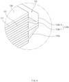
- the overlapping second electrode tabs 122 comprise a second connection surface 123a connected to a second coating portion 121 and a second bonding surface 123b extending from the second connection surface 123a, and the second bonding surface 123b comprises a second uncut part 123b-1 connected to the second connection surface and a second cut part 123b-2 which extends from the second uncut part 123b-1 and of which both vertex portions are provided as inclined surfaces.
- the electrode assembly 100 having the above-described structure comprises the first electrode tab 112 and the second electrode tab 122.
- first electrode tab 112 and the second electrode tab 122 are provided as the inclined surfaces having inclined angles on both side surfaces, respectively, an area of the electrode tab may be significantly secured, and resistance between the electrode tab and the electrode lead may be significantly reduced.
- Each of the inclined surfaces has an inclination angle equal to or less than 45° when viewed with respect to a boundary between the electrode tab and the coating portion.
- the electrode lead 200 is coupled to the electrode tab and comprises a first electrode lead 210 coupled to the first electrode tab 112 and a second electrode lead 220 coupled to the second electrode tab 122.
- the first electrode lead 210 is coupled to the first cut part 113b-2
- the second electrode lead 220 is coupled to the second cut part 123b-2.
- the external force transmitted to the electrode lead is effectively dispersed by the cut parts 113b-2 and 123b-2
- the external force may be transmitted to the uncut parts 113b-1 and 123b-1 to weaken the bonding force of each of the uncut parts 113b-1 and 123b-1.
- the pouch 300 is configured to accommodate the electrode assembly. That is the pouch 300 accommodates the electrode assembly 100 in a state in which a front end of the electrode lead 200 is pulled out to the outside.
- the secondary battery according to the first embodiment of the present invention comprises the electrode assembly 100 provided with the electrode tab having a trapezoidal shape to significantly secure an area of the electrode tab.
- a method for manufacturing the secondary battery according to the first embodiment of the present invention comprises an electrode preparation step (S10), an electrode assembly manufacturing step (S20), a non-coating portion bonding step (S30), a display part formation step ( S40), an electrode tab manufacturing step (S50), a display part inspection step (S60), an uncut part reinforcement step (S65), a tape attachment step (S67), an electrode lead coupling step (S70), and a pouch accommodation step (S80).
- an electrode provided with a coating portion coated with an electrode active material and a non-coating portion that is not coated with the electrode active material is prepared.
- the electrode comprises a first electrode 110 and a second electrode 120, which have different polarities.
- a first electrode active material is applied to one side of a collector to form a first coating portion 111, and a first non-coating portion 113 is formed on the other side of the collector, which is not coated with the first electrode active material.
- a second electrode active material is applied to one side of the collector to form a second coating portion 121, and a second non-coating portion is formed on the other side of the collector, which is not coated with the second electrode active material.
- electrodes and separators are alternately stacked to prepare an electrode assembly, and the electrodes are stacked so that non-coating portions overlap each other.
- the first electrode 110 and the second electrode 120 are alternately stacked with the separator 130 therebetween.
- the first non-coating portion 113 of the first electrode 110 and the second non-coating portion 123 of the second electrode 120 are disposed to face different directions.
- the first non-coating portion 113 of the first electrode 110 is disposed to be pulled out in a left direction of the electrode assembly 100 when viewed in FIG. 2
- the second non-coating portion 123 of the second electrode 120 is disposed to be pulled out in a right direction of the electrode assembly 100 when viewed in FIG 2 .
- the overlapping non-coating portions are welded to be integrated with each other. That is, in the non-coating portion bonding step (S30), the overlapped first non-coating portions 113 are welded to be integrated with each other, and the overlapping second non-coating portions 123 are welded to be integrated with each other.
- the non-coating portion is provided with a connection surface connected to the coating portion and a bonding surface extending from the connection surface.
- the first non-coating portion 113 comprises a first connection surface 113a connected to the first coating portion 111 and a first bonding surface 113b extending from the first connection surface 113a.
- first bonding surface 113b is welded.
- the second non-coating portion 123 comprises a second connection surface 123a connected to the second coating portion 121 and a second bonding surface 123b extending from the second connection surface 123a.
- a second connection surface 123a connected to the second coating portion 121 and a second bonding surface 123b extending from the second connection surface 123a.
- only the second bonding surface 123b is welded.
- the display part forming step (S40) is performed to form a display part for setting a cutting point on a surface of the overlapping non-coating portions and comprises a photographing process, an inspection process, and a display process.
- the surface of the overlapping non-coating portions are photographed. That is, in the photographing process, the first non-coating portion 113 is photographed to calculate an image of the first non-coating portion, and the overlapping second non-coating portion 123 is photographed to calculate an image of the second non-coating portion.
- the inspection process whether the photographed image of the first non-coating portion is within a preset range of a previously input image of the first non-coating portion is inspected. Then, when the photographed image is within the preset range of the previously input image, it is determined as a normal image, and when the photographed image is out of the preset range of the previously input image, it is determined as a defective image. Also, in the inspection process, whether the photographed image of the second non-coating portion is within a preset range of a previously input image of the second non-coating portion is inspected. Then, when the photographed image is within the preset range of the previously input image, it is determined as a normal image, and when the photographed image is out of the preset range of the previously input image, it is determined as a defective image.
- a display part 114 for setting a cutting point on a surface of the bonded first non-coating portion 113 is formed, and when the photographed image of the second non-coating portion is within the preset range of the previously input image of the second non-coating portion, a display part 124 for setting a cutting point on a surface of the bonded second non-coating portion 113 is formed.
- the display part may be used as a reference point when manufacturing the electrode tab by cutting the non-coating portion to improve cutting accuracy and continuously manufacture the electrode tab having uniform quality.
- the display part are formed on each of both vertex portions of the surface of the overlapping non-coating portions. That is, in the display process, the display part 114 for setting the cutting point on each of both the vertex portions on the surface of the overlapping first non-coating portions 113 is formed, and the display part 124 for setting the cutting point on each of both the vertex portions on the surface of the overlapping second non-coating portions 123 is formed.
- the display part is formed as a display hole passing from a top surface to a bottom surface of the overlapping non-coating portions. That is, a display hole is formed to pass from a top surface to a bottom surface of the overlapping first non-coating portions 113, and a display hole is formed to pass from a top surface to a bottom surface of the overlapping second non-coating portions 123.
- the display part may be stably and conveniently formed on the surface of the non-coating portion.
- the bonding surface is divided into the uncut part connected to the connection surface and the cut part extending from the uncut part, and then, the display parts for setting the cutting points are respectively formed on both the vertex portions of the cut part.
- a first bonding surface 113b of the first non-coating portion 113 is divided into a first uncut part 113b-1 connected to a first connection surface 113a and a first cut part 113b-2 extending from the first uncut part 113b-1, and then, the display part 114 for setting the cutting point is formed on each of both vertex portions of the first cut part 113b-2.
- a second bonding surface 123b of the second non-coating portion 123 is divided into a second uncut part 123b-1 connected to a second connection surface 123a and a second cut part 123b-2 extending from the second uncut part 123b-1, and then, the display part 124 for setting the cutting point is formed on each of both vertex portions of the second cut part 123b-2.
- the bonding force of the bonding surface may be significantly weakened.
- the weakening of the bonding force may occur at a boundary between the connection surface and the bonding surface.
- the uncut part that is not cut is formed on the bonding surface connected to the connection surface, and thus, the weakening of the bonding force between the connection surface and the bonding surface may be compensated.
- the electrode tab is manufactured by cutting the non-coating portion with respect to the display part. That is, in the electrode tab manufacturing step (S50), both vertexes of the first non-coating portion 113 are cut to be inclined with respect to the display part 114 to manufacture a first electrode tab 112. In addition, both vertexes of the second non-coating portion 123 are cut to be inclined with respect to the display part 124 to manufacture a second electrode tab 122.
- both the vertex portions of the cut part except for the uncut part are cut to be inclined with respect to the display part to manufacture the electrode tab. That is, both the vertexes of the first cut part 113b-2 are cut to be inclined with respect to the display part 114 formed on the first cut part 113b-2 except for the first uncut part 113b-1, and both the vertexes of the second cut part 123b-2 are cut to be inclined with respect to the display part 114 formed on the second cut part 123b-2 except for the second uncut part 123b-1.
- the weakening of the bonding force of the electrode tab may be significantly prevented through the uncut part.
- both the vertex portions of the non-coating portions that overlap each other in addition to all the display parts are cut to be inclined so that the display parts do not remain on the cut electrode tab. That is, when cutting the first non-coating portion 113, the first non-coating portion 113 is cut so that all the display parts 114 are removed, and when cutting the second non-coating portion 123, the second non-coating portion 123 is cut so that all the display parts 124 are removed.
- the display part is not formed on the first and second electrode tabs 112 and 122, quality may be improved.
- the non-coating portions of the electrodes are cut at once to significantly reduce a cutting time.
- the display part inspection step S60 is performed for inspecting whether the display part remains on the electrode tab. That is, whether the display part remains on the electrode tab is inspected by comparing a photographed image of the electrode tab with a previously input image of the electrode tab.
- the first electrode tab 112 is photographed to inspect whether the display part remains on the first electrode tab by comparing the photographed image of the first electrode tab with the previously input image.
- the second electrode tab 122 is photographed to inspect whether the display part remains on the second electrode tab by comparing the photographed image of the second electrode tab with the previously input image.
- the uncut part of the bonding surface is bonded again to reinforce the bonding force of the uncut part. That is, in the uncut part reinforcement step (S65), the cut part may be cut to weaken the bonding force of the uncut part. As a result, the uncut part may be bonded again to reinforce the bonding force of the uncut part.
- the uncut part 113b-1 of the first bonding surface 113b is compressed to reinforce the bonding force
- the uncut part 123b-1 of the second bonding surface 123b is compressed to reinforce the bonding force
- a protective table is attached to the uncut part to protect the uncut part after the uncut part reinforcement step (s65). That is, a protective tape 140 is attached to each of both side surfaces of each of the uncut parts 113b-1 and 123b-1.
- the first bonding surface 113b and the second bonding surface 123b may be protected against an external impact to prevent the bonding force of the first bonding surface 113b and the second bonding surface 123b from being weakened.
- an electrode lead 200 is coupled to the electrode tab.
- the electrode lead 200 comprises a first electrode lead 210 and a second electrode lead 220.
- the first electrode lead 210 is welded and coupled to the first electrode tab 112, and the second electrode lead 220 is welded and coupled to the second electrode tab 122.
- the electrode lead is coupled to the cut part to prevent the bonding force of the uncut part from being weakened.
- an electrode assembly to which the electrode lead is coupled is accommodated in a pouch 300 to complete the secondary battery.
- the notching process for forming the electrode tab may be omitted to simplify the process.
- the overlapping non-coating portions may be cut at once through the display part to form the electrode tab, thereby improving the cutting accuracy and continuously manufacturing the electrode tab having the uniform quality.
- a display hole that is a display part is defined to be inclined in each of both vertex portions of the overlapping non-coating portions in a display part formation step (S40) of forming the display part for setting a cutting point on a surface of the bonded non-coating portion, and both the vertex portions of the non-coating portion are cut to be inclined along the display hole formed in the non-coating portion in the electrode tab manufacturing step (S50).
- a display hole 514 is formed lengthily in the same direction as a direction, in which a first non-coating portion 113 is cut, at both vertex portions on a surface of the first non-coating portion 113
- a display hole 624 is formed lengthily in the same direction as a direction, in which a second non-coating portion 123 is cut, at both vertex portions on a surface of the second non-coating portion 123.
- the non-coating portion when cutting the non-coating portion, since the non-coating portion is cut based on the display holes, the non-coating portion may be easily cut to improve cutting direction and accuracy.
- Each of the display holes 514 and 624 may have a rectangular shape. Thus, when cutting the non-coating portion, the non-coating portion may be easily cut so that the display holes do not remain.
Landscapes
- Chemical & Material Sciences (AREA)
- Chemical Kinetics & Catalysis (AREA)
- Electrochemistry (AREA)
- General Chemical & Material Sciences (AREA)
- Engineering & Computer Science (AREA)
- Manufacturing & Machinery (AREA)
- Connection Of Batteries Or Terminals (AREA)
- Battery Electrode And Active Subsutance (AREA)
Abstract
Description
- The present application claims the benefit of the priority of
Korean Patent Application No. 10-2019-0082273, filed on July 08, 2019 - The present invention relates to a secondary battery and a method for manufacturing the same, and more particularly, to a secondary battery, in which a notching step is removed to simplify processes, and a method for manufacturing the same.
- In general, secondary batteries refer to chargeable and dischargeable batteries, unlike primary batteries that are not chargeable. The secondary batteries are being widely used in the high-tech electronic fields such as mobile phones, notebook computers, and camcorders.
- The secondary battery comprises an electrode assembly in which electrodes and separators are alternately stacked and a case accommodating the electrode assembly. A method for manufacturing the secondary battery having the above-described above structure comprises a step of manufacturing an electrode, a step of manufacturing an electrode assembly, and a step of accommodating the electrode assembly in a case.
- Here, the method for manufacturing the secondary battery comprises a notching process for forming a tab in the step of manufacturing the electrode.
- However, the method for manufacturing the secondary battery according to the present invention has a problem in which a lot of time is taken to manufacture the electrode due to the notching process, and particularly, many defects occur due to burrs and delamination that occur during the notching process.
- The present invention is invented to solve the above problems, and an object of the present invention is to provide a secondary battery, in which a notching process of processing an electrode tab is removed to simplify processes, thereby significantly reducing a time taken to manufacture the secondary battery, and particularly, significantly reducing a defect rate by preventing burrs and delamination that occur during the notching process, and a method for manufacturing the secondary battery.
- A method for manufacturing a secondary battery according to the present invention for achieving the above object comprises: an electrode preparation step (S10) of preparing electrodes, each of which is provided with a coating portion coated with an electrode active material and a non-coating portion that is not coated with the electrode active material; an electrode assembly manufacturing step (S20) of alternately stacking the electrodes and separators to manufacture an electrode assembly, wherein the electrodes are stacked so that the non-coating portions overlap each other; a non-coating portion bonding step (S30) of bonding the overlapping non-coating portions to each other; a display part formation step (S40) of forming a display part for setting a cutting point on a surface of the bonded non-coating portion; and an electrode tab manufacturing step (S50) of cutting the bonded non-coating portion with respect to the display part to manufacture an electrode tab.
- The display part formation process (S40) may comprise: a photographing process of photographing the surface of the overlapping non-coating portions; an inspection process of inspecting whether the photographed image of the non-coating portions is within a set range of a previously input image of the non-coating portions; and a display process of forming a display part for setting the cutting point on the surface of the overlapping non-coating portions when the image of the non-coating portions, which is photographed in the inspection process, is within the set range of the previously input image of the non-coating portions.
- In the display process, a display part for setting the cutting point may be formed on each of both vertex portions on the surface of the overlapping non-coating portions, and in the electrode tab manufacturing step (S50), both the vertex portions of the overlapping non-coating portions may be cut to be inclined with respect to the display part to manufacture the electrode tab.
- The display part may be formed as a display hole passing from a top surface to a bottom surface of the overlapping non-coating portions.
- Each of the non-coating portions may comprise a connection surface connected to the coating portion and a bonding surface extending from the connection surface, in the non-coating bonding step (S30), the overlapping non-coating portions may be bonded to each other through the bonding surface, in the display process, the bonding surface may be divided into an uncut part connected to the connection surface and a cut part extending from the uncut part, and the display part for setting the cutting point may be formed on each of both vertex portions of the cut part, and in the electrode tab manufacturing step (S50), both the vertex portions of the cut part may be cut to be inclined with respect to the display part to manufacture the electrode tab.
- The display hole may be formed to be inclined in both the vertex portions of the overlapping non-coating portions, and in the electrode tab manufacturing step (S50), both the vertex portions of the non-coating portions may be cut to be inclined along the display hole defined in the non-coating portion.
- In the electrode tab manufacturing step (S50), the non-coating portions in addition to all the display part may be cut to be inclined so that the display parts do not remain on the electrode tab.
- The method may further comprise, after the electrode tab manufacturing step (S50), a display part inspection step (S60) of inspecting whether the display parts remain on the electrode tab, wherein, in the display part inspection step (S60), the electrode tab is photographed, and a photographed image of the electrode and a previously input image are compared with each other to inspect whether the display parts remain on the electrode tab.
- The method may further comprise, after the display part inspection step (S60), an uncut part reinforcement step (S65) of bonding the uncut part of the bonding surface again to reinforce bonding force of the uncut part.
- The method may further comprise, after the uncut part reinforcement step (S65), a tape attachment step (S67) of attaching a protective tape on the uncut part to protect the uncut part.
- The method may further comprise, after the tape attachment step (S67),; an electrode lead coupling step (S70) of coupling an electrode lead to the electrode tab; and a pouch accommodation step (S80) of accommodating the electrode assembly, to which the electrode lead is coupled, in a pouch to complete the secondary battery.
- A secondary battery manufactured by the method for manufacturing the secondary battery comprises: an electrode assembly in which electrodes, each of which is provided with a coating portion coated with an electrode active material and an electrode tab that is not coated with the electrode active material, and separators are alternately stacked, wherein the electrodes are stacked so that the electrode tabs overlap each other, wherein the overlapping electrode tabs comprise a connection surface connected to the coating portion and a bonding surface extending from the connection surface, and the bonding surface comprises an uncut part connected to the connection surface and a cut part which extends from the uncut part and of which both vertex portions are provided as inclined surfaces.
- First: the method for manufacturing the secondary battery according to the present invention may comprise the electrode preparation step, the electrode assembly manufacturing step, the non-coating portion bonding step, the display part formation step, and the electrode tab manufacturing step. Due to these features, the notching process for forming the electrode tab when the electrode is manufactured may be omitted to increase in simplification of the process, and particularly, the non-coating portion may be cut with respect to the display part to obtain the cutting accuracy and the uniform cutting force, thereby continuously manufacturing the electrode assembly having the uniform quality.
- Second: in the method for manufacturing the secondary battery according to the present invention, the display part formation step may comprise the photographing process, the inspection process, and the display process. Due to these features, the display part may be disposed at the same position on the surface of the non-coating portion to obtain the cutting accuracy and the uniform cutting force.
- Third: in the method for manufacturing the secondary battery according to the present invention, the display part may be formed on both the vertex portions of the non-coating portion with respect to the display part may be cut to be inclined. Due to this feature, the area of the electrode tab may be maximally secured.
- Fourth: in the method for manufacturing the secondary battery according to the present invention, the uncut part of the bonding surface of the bonded non-coating portion may be provided. Due to this feature, the bonding force of the portion of the binding surface connected to the connection surface of the non-coating portion may be stably secured.
- Fifth: in the method for manufacturing the secondary battery according to the present invention, the display part may be cut when the electrode tab is manufactured. Due to this feature, the display part may not remain on the electrode tab, and thus, the damage due to the display part remaining on the electrode tab may be previously prevented.
- Sixth: in the method for manufacturing the secondary battery according to the present invention, after the cut part of the non-coating portion is cut to manufacture the electrode tab, the uncut part may be bonded again. Due to this feature, the bonding force of the uncut part may be reinforced. That is, when cutting the cut portion, the bonding force of the uncut part may be weakened. Accordingly, the uncut part may be bonded again to reinforce the bonding force of the uncut part.
- Seventh: in the method for manufacturing the secondary battery according to the present invention, the protective tape may be attached to the uncut part. Due to this feature, the bonding force of the uncut part may be prevented from being weakened by the external impact.
-
-
FIG. 1 is a cross-sectional view of a secondary battery according to a first embodiment of the present invention. -
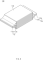
FIG. 2 is a perspective view of an electrode assembly according to the first embodiment of the present invention. -
FIG. 3 is an enlarged view of a portion A illustrated inFIG. 2 . -
FIG. 4 is an enlarged view of a portion B illustrated inFIG. 2 . -
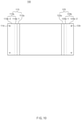
FIG. 5 is a plan view ofFIG. 2 . -
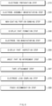
FIG. 6 is a flowchart illustrating a method for manufacturing the electrode assembly according to the first embodiment of the present invention. -
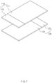
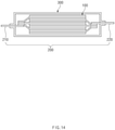
FIGS. 7 to 14 are process views illustrating the method for manufacturing the electrode assembly according to the first embodiment of the present invention, whereinFIG. 7 is a view illustrating an electrode manufacturing step,FIG. 8 is a view illustrating an electrode assembly manufacturing step,FIG. 9 is a view illustrating a non-coating portion bonding step,FIG. 10 is a view illustrating a display part formation step,FIG. 11 is a view illustrating an electrode tab manufacturing step,FIG. 12 is a view illustrating a tape attachment step,FIG. 13 is a view illustrating an electrode lead coupling step, andFIG. 14 is a view illustrating a pouch accommodation step. -
FIG. 15 is a plan view of a secondary battery according to a second embodiment of the present invention. - Hereinafter, embodiments of the present invention will be described in detail with reference to the accompanying drawings in such a manner that the technical idea of the present invention may easily be carried out by a person with ordinary skill in the art to which the invention pertains. The present invention may, however, be embodied in different forms and should not be construed as limited to the embodiments set forth herein. In the drawings, anything unnecessary for describing the present invention will be omitted for clarity, and also like reference numerals in the drawings denote like elements.
- As illustrated in
FIG. 1 , a secondary battery according to a first embodiment of the present invention comprises anelectrode assembly 100, anelectrode lead 200 coupled to theelectrode assembly 100, and apouch 300 accommodating theelectrode assembly 100 in a state in which a front end of theelectrode lead 200 is pulled out to the outside. - As illustrated in
FIGS. 2 to 5 , theelectrode assembly 100 has a structure in which a plurality of electrodes and a plurality of separators are alternately stacked. Each of the electrodes comprises a coating portion coated with an electrode active material and an electrode tab that is a non-coating portion that is not coated with the electrode active material. Here, in theelectrode assembly 100, the electrodes are stacked so that the electrode tabs overlap each other. - A plurality of electrodes comprise a
first electrode 110 and asecond electrode 120. Theseparator 130 is disposed between thefirst electrode 110 and thesecond electrode 120. - For example, in the
electrode assembly 100, thefirst electrode 110 and thesecond electrode 120 are alternately stacked in the state in which theseparator 130 is disposed therebetween. Thefirst electrode 110 comprises a first coating portion coated with a first electrode active material and afirst electrode tab 112 that is a non-coating portion that is not coated with the first electrode active material. Also, thesecond electrode 120 comprises asecond coating portion 121 coated with a second electrode active material and a second electrode tab that is a non-coating portion that is not coated with the second electrode active material. Here, thefirst electrode tab 112 and thesecond electrode tab 122 are disposed to be pulled out toward both sides of theelectrode assembly 100, respectively. That is, thefirst electrode tab 112 is disposed to be pulled out toward one end (a left end of the electrode assembly when viewed inFIG. 2 ) of theelectrode assembly 100, and thesecond electrode tab 122 is disposed to be pulled out toward the other end (a right end of the electrode assembly when viewed inFIG. 2 ) of theelectrode assembly 100. - The overlapping electrode tabs comprise a connection surface connected to the coating portion and a bonding surface extending from the connection surface, and the bonding surface comprises an uncut part connected to the connection surface and a cut part which extends from the uncut part and of which both vertex portions are provided as inclined surfaces.
- For example, referring to
FIG. 3 , the overlappingfirst electrode tabs 112 comprise afirst connection surface 113a connected to afirst coating portion 111 and afirst bonding surface 113b extending from thefirst connection surface 113a, and thefirst bonding surface 113b comprises a firstuncut part 113b-1 connected to the first connection surface and afirst cut part 113b-2 which extends from the firstuncut part 113b-1 and of which both vertex portions are provided as inclined surfaces. Referring toFIG. 4 , the overlappingsecond electrode tabs 122 comprise asecond connection surface 123a connected to asecond coating portion 121 and asecond bonding surface 123b extending from thesecond connection surface 123a, and thesecond bonding surface 123b comprises a seconduncut part 123b-1 connected to the second connection surface and asecond cut part 123b-2 which extends from the seconduncut part 123b-1 and of which both vertex portions are provided as inclined surfaces. - The
electrode assembly 100 having the above-described structure comprises thefirst electrode tab 112 and thesecond electrode tab 122. Thus, since thefirst electrode tab 112 and thesecond electrode tab 122 are provided as the inclined surfaces having inclined angles on both side surfaces, respectively, an area of the electrode tab may be significantly secured, and resistance between the electrode tab and the electrode lead may be significantly reduced. - Each of the inclined surfaces has an inclination angle equal to or less than 45° when viewed with respect to a boundary between the electrode tab and the coating portion.
- The
electrode lead 200 is coupled to the electrode tab and comprises afirst electrode lead 210 coupled to thefirst electrode tab 112 and asecond electrode lead 220 coupled to thesecond electrode tab 122. - Here, the
first electrode lead 210 is coupled to thefirst cut part 113b-2, and thesecond electrode lead 220 is coupled to thesecond cut part 123b-2. Thus, after the external force transmitted to the electrode lead is effectively dispersed by thecut parts 113b-2 and 123b-2, the external force may be transmitted to theuncut parts 113b-1 and 123b-1 to weaken the bonding force of each of theuncut parts 113b-1 and 123b-1. - The
pouch 300 is configured to accommodate the electrode assembly. That is thepouch 300 accommodates theelectrode assembly 100 in a state in which a front end of theelectrode lead 200 is pulled out to the outside. - Thus, the secondary battery according to the first embodiment of the present invention comprises the
electrode assembly 100 provided with the electrode tab having a trapezoidal shape to significantly secure an area of the electrode tab. - Hereinafter, a method for manufacturing the secondary battery according to the first embodiment of the present invention will be described.
- As illustrated in
FIG. 6 , a method for manufacturing the secondary battery according to the first embodiment of the present invention comprises an electrode preparation step (S10), an electrode assembly manufacturing step (S20), a non-coating portion bonding step (S30), a display part formation step ( S40), an electrode tab manufacturing step (S50), a display part inspection step (S60), an uncut part reinforcement step (S65), a tape attachment step (S67), an electrode lead coupling step (S70), and a pouch accommodation step (S80). - As illustrated in
FIG. 7 , in the electrode preparation step (S10), an electrode provided with a coating portion coated with an electrode active material and a non-coating portion that is not coated with the electrode active material is prepared. Here, the electrode comprises afirst electrode 110 and asecond electrode 120, which have different polarities. - That is, in the
first electrode 110, a first electrode active material is applied to one side of a collector to form afirst coating portion 111, and a firstnon-coating portion 113 is formed on the other side of the collector, which is not coated with the first electrode active material. - In the
second electrode 120, a second electrode active material is applied to one side of the collector to form asecond coating portion 121, and a second non-coating portion is formed on the other side of the collector, which is not coated with the second electrode active material. - In the electrode assembly manufacturing step (S20), as illustrated in
FIG. 8 , electrodes and separators are alternately stacked to prepare an electrode assembly, and the electrodes are stacked so that non-coating portions overlap each other. - That is, in the electrode assembly manufacturing step (S20), the
first electrode 110 and thesecond electrode 120 are alternately stacked with theseparator 130 therebetween. Here, the firstnon-coating portion 113 of thefirst electrode 110 and the secondnon-coating portion 123 of thesecond electrode 120 are disposed to face different directions. For example, the firstnon-coating portion 113 of thefirst electrode 110 is disposed to be pulled out in a left direction of theelectrode assembly 100 when viewed inFIG. 2 , and the secondnon-coating portion 123 of thesecond electrode 120 is disposed to be pulled out in a right direction of theelectrode assembly 100 when viewed inFIG 2 . - In the non-coating portion bonding step (S30), as illustrated in
FIG. 9 , the overlapping non-coating portions are welded to be integrated with each other. That is, in the non-coating portion bonding step (S30), the overlapped firstnon-coating portions 113 are welded to be integrated with each other, and the overlapping secondnon-coating portions 123 are welded to be integrated with each other. - As a result, the non-coating portion is provided with a connection surface connected to the coating portion and a bonding surface extending from the connection surface.
- That is, the first
non-coating portion 113 comprises afirst connection surface 113a connected to thefirst coating portion 111 and afirst bonding surface 113b extending from thefirst connection surface 113a. Here, only thefirst bonding surface 113b is welded. - The second
non-coating portion 123 comprises asecond connection surface 123a connected to thesecond coating portion 121 and asecond bonding surface 123b extending from thesecond connection surface 123a. Here, only thesecond bonding surface 123b is welded. - As illustrated in
FIGS. 10 , the display part forming step (S40) is performed to form a display part for setting a cutting point on a surface of the overlapping non-coating portions and comprises a photographing process, an inspection process, and a display process. - In the photographing process, the surface of the overlapping non-coating portions are photographed. That is, in the photographing process, the first
non-coating portion 113 is photographed to calculate an image of the first non-coating portion, and the overlapping secondnon-coating portion 123 is photographed to calculate an image of the second non-coating portion. - In the inspection process, whether the photographed image of the non-coating portion is within a preset range of a previously input image of the non-coating portion is inspected.
- That is, in the inspection process, whether the photographed image of the first non-coating portion is within a preset range of a previously input image of the first non-coating portion is inspected. Then, when the photographed image is within the preset range of the previously input image, it is determined as a normal image, and when the photographed image is out of the preset range of the previously input image, it is determined as a defective image. Also, in the inspection process, whether the photographed image of the second non-coating portion is within a preset range of a previously input image of the second non-coating portion is inspected. Then, when the photographed image is within the preset range of the previously input image, it is determined as a normal image, and when the photographed image is out of the preset range of the previously input image, it is determined as a defective image.
- In the display process, when the photographed image of the non-coating portion is within the preset range of the previously input image of the non-coating portion, a display part for setting a cutting point on the surface of the overlapping non-coating portions is formed.
- That is, in the display process, when the photographed image of the first non-coating portion is within the preset range of the previously input image of the first non-coating portion, a
display part 114 for setting a cutting point on a surface of the bonded firstnon-coating portion 113 is formed, and when the photographed image of the second non-coating portion is within the preset range of the previously input image of the second non-coating portion, adisplay part 124 for setting a cutting point on a surface of the bonded secondnon-coating portion 113 is formed. - The display part may be used as a reference point when manufacturing the electrode tab by cutting the non-coating portion to improve cutting accuracy and continuously manufacture the electrode tab having uniform quality.
- Particularly, in the display process, the display part are formed on each of both vertex portions of the surface of the overlapping non-coating portions. That is, in the display process, the
display part 114 for setting the cutting point on each of both the vertex portions on the surface of the overlapping firstnon-coating portions 113 is formed, and thedisplay part 124 for setting the cutting point on each of both the vertex portions on the surface of the overlapping secondnon-coating portions 123 is formed. - The display part is formed as a display hole passing from a top surface to a bottom surface of the overlapping non-coating portions. That is, a display hole is formed to pass from a top surface to a bottom surface of the overlapping first
non-coating portions 113, and a display hole is formed to pass from a top surface to a bottom surface of the overlapping secondnon-coating portions 123. Thus, the display part may be stably and conveniently formed on the surface of the non-coating portion. - In the display process, the bonding surface is divided into the uncut part connected to the connection surface and the cut part extending from the uncut part, and then, the display parts for setting the cutting points are respectively formed on both the vertex portions of the cut part.
- That is, in the display process, a
first bonding surface 113b of the firstnon-coating portion 113 is divided into a firstuncut part 113b-1 connected to afirst connection surface 113a and afirst cut part 113b-2 extending from the firstuncut part 113b-1, and then, thedisplay part 114 for setting the cutting point is formed on each of both vertex portions of thefirst cut part 113b-2. Also, asecond bonding surface 123b of the secondnon-coating portion 123 is divided into a seconduncut part 123b-1 connected to asecond connection surface 123a and asecond cut part 123b-2 extending from the seconduncut part 123b-1, and then, thedisplay part 124 for setting the cutting point is formed on each of both vertex portions of thesecond cut part 123b-2. - Here, when the entire bonding surface is cut to be inclined, the bonding force of the bonding surface may be significantly weakened. In particular, the weakening of the bonding force may occur at a boundary between the connection surface and the bonding surface. In order to solve this problem, the uncut part that is not cut is formed on the bonding surface connected to the connection surface, and thus, the weakening of the bonding force between the connection surface and the bonding surface may be compensated.
- In the electrode tab manufacturing step (S50), as illustrated in
FIG. 11 , the electrode tab is manufactured by cutting the non-coating portion with respect to the display part. That is, in the electrode tab manufacturing step (S50), both vertexes of the firstnon-coating portion 113 are cut to be inclined with respect to thedisplay part 114 to manufacture afirst electrode tab 112. In addition, both vertexes of the secondnon-coating portion 123 are cut to be inclined with respect to thedisplay part 124 to manufacture asecond electrode tab 122. - Here, in the electrode tab manufacturing step (S50), both the vertex portions of the cut part except for the uncut part are cut to be inclined with respect to the display part to manufacture the electrode tab. That is, both the vertexes of the
first cut part 113b-2 are cut to be inclined with respect to thedisplay part 114 formed on thefirst cut part 113b-2 except for the firstuncut part 113b-1, and both the vertexes of thesecond cut part 123b-2 are cut to be inclined with respect to thedisplay part 114 formed on thesecond cut part 123b-2 except for the seconduncut part 123b-1. Thus, the weakening of the bonding force of the electrode tab may be significantly prevented through the uncut part. - Particularly, in the electrode tab manufacturing step (S50), both the vertex portions of the non-coating portions that overlap each other in addition to all the display parts are cut to be inclined so that the display parts do not remain on the cut electrode tab. That is, when cutting the first
non-coating portion 113, the firstnon-coating portion 113 is cut so that all thedisplay parts 114 are removed, and when cutting the secondnon-coating portion 123, the secondnon-coating portion 123 is cut so that all thedisplay parts 124 are removed. Thus, since the display part is not formed on the first andsecond electrode tabs - The display part inspection step S60 is performed for inspecting whether the display part remains on the electrode tab. That is, whether the display part remains on the electrode tab is inspected by comparing a photographed image of the electrode tab with a previously input image of the electrode tab.
- That is, in the display part inspection step (S60), the
first electrode tab 112 is photographed to inspect whether the display part remains on the first electrode tab by comparing the photographed image of the first electrode tab with the previously input image. Also, thesecond electrode tab 122 is photographed to inspect whether the display part remains on the second electrode tab by comparing the photographed image of the second electrode tab with the previously input image. - In the uncut part reinforcement step (S65), the uncut part of the bonding surface is bonded again to reinforce the bonding force of the uncut part. That is, in the uncut part reinforcement step (S65), the cut part may be cut to weaken the bonding force of the uncut part. As a result, the uncut part may be bonded again to reinforce the bonding force of the uncut part.
- In the uncut part reinforcement step (S65), the
uncut part 113b-1 of thefirst bonding surface 113b is compressed to reinforce the bonding force, and theuncut part 123b-1 of thesecond bonding surface 123b is compressed to reinforce the bonding force. - In the tape attachment step (S67), as illustrated in
FIG. 12 , a protective table is attached to the uncut part to protect the uncut part after the uncut part reinforcement step (s65). That is, aprotective tape 140 is attached to each of both side surfaces of each of theuncut parts 113b-1 and 123b-1. Thus, thefirst bonding surface 113b and thesecond bonding surface 123b may be protected against an external impact to prevent the bonding force of thefirst bonding surface 113b and thesecond bonding surface 123b from being weakened. - In the electrode lead coupling step (S70), as illustrated in
FIG. 13 , anelectrode lead 200 is coupled to the electrode tab. Here, theelectrode lead 200 comprises afirst electrode lead 210 and asecond electrode lead 220. - That is, in the electrode lead coupling step (S70), the
first electrode lead 210 is welded and coupled to thefirst electrode tab 112, and thesecond electrode lead 220 is welded and coupled to thesecond electrode tab 122. - Here, the electrode lead is coupled to the cut part to prevent the bonding force of the uncut part from being weakened.
- In the pouch accommodation step (S80), as illustrated in
FIG. 14 , an electrode assembly to which the electrode lead is coupled is accommodated in apouch 300 to complete the secondary battery. - Therefore, in the method for manufacturing the secondary battery according to the first embodiment of the present invention, the notching process for forming the electrode tab may be omitted to simplify the process. Particularly, the overlapping non-coating portions may be cut at once through the display part to form the electrode tab, thereby improving the cutting accuracy and continuously manufacturing the electrode tab having the uniform quality.
- Hereinafter, in descriptions of another embodiment of the present invention, constituents having the same function as the above-mentioned embodiment have been given the same reference numeral in the drawings, and thus duplicated description will be omitted.
- In a method for manufacturing a secondary battery according to a second embodiment of the present invention, as illustrated in
FIG. 15 , a display hole that is a display part is defined to be inclined in each of both vertex portions of the overlapping non-coating portions in a display part formation step (S40) of forming the display part for setting a cutting point on a surface of the bonded non-coating portion, and both the vertex portions of the non-coating portion are cut to be inclined along the display hole formed in the non-coating portion in the electrode tab manufacturing step (S50). - That is, in the display part formation step (S40), a display hole 514 is formed lengthily in the same direction as a direction, in which a first
non-coating portion 113 is cut, at both vertex portions on a surface of the firstnon-coating portion 113, and a display hole 624 is formed lengthily in the same direction as a direction, in which a secondnon-coating portion 123 is cut, at both vertex portions on a surface of the secondnon-coating portion 123. - Thus, when cutting the non-coating portion, since the non-coating portion is cut based on the display holes, the non-coating portion may be easily cut to improve cutting direction and accuracy.
- Each of the display holes 514 and 624 may have a rectangular shape. Thus, when cutting the non-coating portion, the non-coating portion may be easily cut so that the display holes do not remain.
- Accordingly, the scope of the present invention is defined by the appended claims more than the foregoing description and the exemplary embodiments described therein. Various modifications made within the meaning of an equivalent of the claims of the invention and within the claims are to be regarded to be in the scope of the present invention.
Claims (12)
- A method for manufacturing a secondary battery, the method comprising:an electrode preparation step (S10) of preparing electrodes, each of which is provided with a coating portion coated with an electrode active material and a non-coating portion that is not coated with the electrode active material;an electrode assembly manufacturing step (S20) of alternately stacking the electrodes and separators to manufacture an electrode assembly, wherein the electrodes are stacked so that the non-coating portions overlap each other;a non-coating portion bonding step (S30) of bonding the overlapping non-coating portions to each other;a display part formation step (S40) of forming a display part for setting a cutting point on a surface of the bonded non-coating portion; andan electrode tab manufacturing step (S50) of cutting the bonded non-coating portion with respect to the display part to manufacture an electrode tab.
- The method of claim 1, wherein the display part formation process (S40) comprises:a photographing process of photographing the surface of the overlapping non-coating portions;an inspection process of inspecting whether the photographed image of the non-coating portions is within a set range of a previously input image of the non-coating portions; anda display process of forming a display part for setting the cutting point on the surface of the overlapping non-coating portions when the image of the non-coating portions, which is photographed in the inspection process, is within the set range of the previously input image of the non-coating portions.
- The method of claim 2, wherein, in the display process, a display part for setting the cutting point is formed on each of both vertex portions on the surface of the overlapping non-coating portions, and
in the electrode tab manufacturing step (S50), both the vertex portions of the overlapping non-coating portions are cut to be inclined with respect to the display part to manufacture the electrode tab. - The method of claim 3, wherein the display part is formed as a display hole passing from a top surface to a bottom surface of the overlapping non-coating portions.
- The method of claim 4, wherein each of the non-coating portions comprises a connection surface connected to the coating portion and a bonding surface extending from the connection surface,in the non-coating bonding step (S30), the overlapping non-coating portions are bonded to each other through the bonding surface,in the display process, the bonding surface is divided into an uncut part connected to the connection surface and a cut part extending from the uncut part, and the display part for setting the cutting point is formed on each of both vertex portions of the cut part, andin the electrode tab manufacturing step (S50), both the vertex portions of the cut part are cut to be inclined with respect to the display part to manufacture the electrode tab.
- The method of claim 5, wherein the display hole is formed to be inclined in both the vertex portions of the overlapping non-coating portions, and
in the electrode tab manufacturing step (S50), both the vertex portions of the non-coating portions are cut to be inclined along the display hole defined in the non-coating portion. - The method of claim 6, wherein, in the electrode tab manufacturing step (S50), the non-coating portions in addition to all the display part are cut to be inclined so that the display parts do not remain on the electrode tab.
- The method of claim 6, further comprising, after the electrode tab manufacturing step (S50), a display part inspection step (S60) of inspecting whether the display parts remain on the electrode tab,
wherein, in the display part inspection step (S60), the electrode tab is photographed, and a photographed image of the electrode and a previously input image are compared with each other to inspect whether the display parts remain on the electrode tab. - The method of claim 8, further comprising, after the display part inspection step (S60), an uncut part reinforcement step (S65) of bonding the uncut part of the bonding surface again to reinforce bonding force of the uncut part.
- The method of claim 9, further comprising, after the uncut part reinforcement step (S65), a tape attachment step (S67) of attaching a protective tape on the uncut part to protect the uncut part.
- The method of claim 10, further comprising, after the tape attachment step (S67);an electrode lead coupling step (S70) of coupling an electrode lead to the electrode tab; anda pouch accommodation step (S80) of accommodating the electrode assembly, to which the electrode lead is coupled, in a pouch to complete the secondary battery.
- A secondary battery comprising:an electrode assembly in which electrodes, each of which is provided with a coating portion coated with an electrode active material and an electrode tab that is not coated with the electrode active material, and separators are alternately stacked, wherein the electrodes are stacked so that the electrode tabs overlap each other,wherein the overlapping electrode tabs comprise a connection surface connected to the coating portion and a bonding surface extending from the connection surface, andthe bonding surface comprises an uncut part connected to the connection surface and a cut part which extends from the uncut part and of which both vertex portions are provided as inclined surfaces.
Applications Claiming Priority (2)
| Application Number | Priority Date | Filing Date | Title |
|---|---|---|---|
| KR1020190082273A KR102808476B1 (en) | 2019-07-08 | 2019-07-08 | Secondary battery and method for manufacturing the same |
| PCT/KR2020/006303 WO2021006474A1 (en) | 2019-07-08 | 2020-05-13 | Secondary battery and method for manufacturing same |
Publications (2)
| Publication Number | Publication Date |
|---|---|
| EP3968423A1 true EP3968423A1 (en) | 2022-03-16 |
| EP3968423A4 EP3968423A4 (en) | 2022-11-23 |
Family
ID=74113994
Family Applications (1)
| Application Number | Title | Priority Date | Filing Date |
|---|---|---|---|
| EP20836539.5A Pending EP3968423A4 (en) | 2019-07-08 | 2020-05-13 | SECONDARY BATTERY AND ITS MANUFACTURING METHOD |
Country Status (5)
| Country | Link |
|---|---|
| US (1) | US12355035B2 (en) |
| EP (1) | EP3968423A4 (en) |
| KR (1) | KR102808476B1 (en) |
| CN (1) | CN113939936B (en) |
| WO (1) | WO2021006474A1 (en) |
Families Citing this family (7)
| Publication number | Priority date | Publication date | Assignee | Title |
|---|---|---|---|---|
| KR20230026730A (en) * | 2021-08-18 | 2023-02-27 | 삼성전자주식회사 | Electronic device including battery |
| KR20230034027A (en) * | 2021-09-02 | 2023-03-09 | 주식회사 엘지에너지솔루션 | Lead supply system and control method of the same |
| KR102945307B1 (en) | 2022-01-19 | 2026-03-30 | 에스케이온 주식회사 | Rechargeable-battery |
| KR102848105B1 (en) | 2022-10-21 | 2025-08-21 | 주식회사 엘지에너지솔루션 | Method for manufacturing an electrode assembly |
| JP2025511613A (en) | 2022-10-21 | 2025-04-16 | エルジー エナジー ソリューション リミテッド | Method for manufacturing an electrode assembly |
| KR20250053390A (en) * | 2023-10-13 | 2025-04-22 | 에스케이온 주식회사 | Method for manufacturing battery cell and system of the same |
| KR102839274B1 (en) * | 2023-10-24 | 2025-07-25 | 주식회사 엘지에너지솔루션 | Battery cell manufacturing apparatus, battery cell manufacturing system and method of manufcaturing battery cell |
Family Cites Families (28)
| Publication number | Priority date | Publication date | Assignee | Title |
|---|---|---|---|---|
| KR100612364B1 (en) | 2004-10-28 | 2006-08-16 | 삼성에스디아이 주식회사 | Secondary battery |
| JP5125438B2 (en) | 2007-11-16 | 2013-01-23 | Necエナジーデバイス株式会社 | Lithium ion secondary battery and battery pack using the same |
| KR101108118B1 (en) * | 2008-11-27 | 2012-01-31 | 주식회사 엠플러스 | Secondary Battery Manufacturing Method and Secondary Battery |
| CN102097643B (en) | 2009-09-16 | 2013-11-20 | 三星Sdi株式会社 | Secondary battery and method for manufacturing the same |
| JP5279784B2 (en) * | 2009-09-16 | 2013-09-04 | 三星エスディアイ株式会社 | Secondary battery and method for manufacturing the same |
| KR101136156B1 (en) * | 2009-11-02 | 2012-04-17 | 삼성에스디아이 주식회사 | Secondary battery and method of making the secondary battery |
| US9099691B2 (en) | 2009-11-25 | 2015-08-04 | Samsung Sdi Co., Ltd. | Rechargeable battery |
| KR101156377B1 (en) | 2009-11-30 | 2012-06-13 | 삼성에스디아이 주식회사 | Secondary battery |
| KR101137364B1 (en) | 2009-12-18 | 2012-04-20 | 에스비리모티브 주식회사 | Secondary battery |
| JP5573419B2 (en) * | 2010-06-29 | 2014-08-20 | 株式会社Gsユアサ | Hydrogen storage alloy electrode, manufacturing method thereof, and battery equipped with hydrogen storage alloy electrode |
| JP5891655B2 (en) | 2010-08-30 | 2016-03-23 | ソニー株式会社 | Nonaqueous electrolyte battery, nonaqueous electrolyte battery manufacturing method, insulating material, insulating material manufacturing method, battery pack, electronic device, electric vehicle, power storage device, and power system |
| KR101355834B1 (en) | 2010-12-02 | 2014-01-28 | 주식회사 엘지화학 | Device for Laminating Electrode Assembly Used in Manufacturing Secondary Battery |
| WO2013011748A1 (en) * | 2011-07-15 | 2013-01-24 | Necエナジーデバイス株式会社 | Battery module |
| JP5861589B2 (en) * | 2012-07-27 | 2016-02-16 | 株式会社豊田自動織機 | Power storage device |
| KR101492726B1 (en) | 2013-07-01 | 2015-02-12 | 안광선 | electrode Tap Fuse Apparatus of Battery and method of the Same |
| KR101658973B1 (en) * | 2013-09-23 | 2016-09-22 | 주식회사 엘지화학 | Pouch type secondary battery and secondary battery module comprising the same |
| JP2015106434A (en) | 2013-11-28 | 2015-06-08 | 株式会社豊田自動織機 | Method for manufacturing electrode for power storage device |
| KR20160010080A (en) | 2014-07-18 | 2016-01-27 | 주식회사 엘지화학 | Electrode Assembly Having Position-Variable Lead Joint And Battery Cell Contaning The Same |
| CN107112444B (en) | 2014-11-05 | 2021-01-26 | 24M技术公司 | Electrochemical cell with semi-solid electrode and method of making same |
| JP2016100282A (en) * | 2014-11-25 | 2016-05-30 | 株式会社豊田自動織機 | Manufacturing method for electrode |
| KR102065736B1 (en) * | 2015-11-04 | 2020-01-13 | 주식회사 엘지화학 | Method for preparing crude cell for lithium secondary battery |
| KR102152213B1 (en) * | 2016-07-29 | 2020-09-04 | 주식회사 엘지화학 | Manufacturing method of electrode assembly and manufacturing method of secondary battery including the same |
| JP2018113190A (en) * | 2017-01-13 | 2018-07-19 | 株式会社日立製作所 | Manufacturing method of multilayer secondary battery |
| KR102352011B1 (en) * | 2017-02-23 | 2022-01-18 | 주식회사 엘지에너지솔루션 | Method for Preparation of Electrode Assembly Comprising Step of Assigning Electrode Plates |
| JP2018152239A (en) | 2017-03-13 | 2018-09-27 | 株式会社豊田自動織機 | Device for conveying electrode material |
| KR102366429B1 (en) | 2017-09-08 | 2022-02-23 | 주식회사 엘지에너지솔루션 | Electrodes with Improved Welding Characteristics of Electrode Tabs and Secondary Battery Using the same |
| JP6853762B2 (en) | 2017-09-28 | 2021-03-31 | プライムアースEvエナジー株式会社 | Secondary battery |
| JP2019102196A (en) | 2017-11-29 | 2019-06-24 | トヨタ自動車株式会社 | Manufacturing method of battery |
-
2019
- 2019-07-08 KR KR1020190082273A patent/KR102808476B1/en active Active
-
2020
- 2020-05-13 WO PCT/KR2020/006303 patent/WO2021006474A1/en not_active Ceased
- 2020-05-13 US US17/625,011 patent/US12355035B2/en active Active
- 2020-05-13 EP EP20836539.5A patent/EP3968423A4/en active Pending
- 2020-05-13 CN CN202080042028.5A patent/CN113939936B/en active Active
Also Published As
| Publication number | Publication date |
|---|---|
| CN113939936A (en) | 2022-01-14 |
| KR102808476B1 (en) | 2025-05-16 |
| EP3968423A4 (en) | 2022-11-23 |
| US20220285735A1 (en) | 2022-09-08 |
| WO2021006474A1 (en) | 2021-01-14 |
| US12355035B2 (en) | 2025-07-08 |
| CN113939936B (en) | 2024-06-25 |
| KR20210006231A (en) | 2021-01-18 |
Similar Documents
| Publication | Publication Date | Title |
|---|---|---|
| US12355035B2 (en) | Secondary battery and method for manufacturing the same | |
| US10833372B2 (en) | Rectangular secondary battery | |
| JP7027634B2 (en) | Battery module | |
| US11757124B2 (en) | Electrode assembly for secondary battery and method for manufacturing the same | |
| US12401087B2 (en) | Pouch, secondary battery comprising the same, and method for manufacturing the secondary battery | |
| US20210126325A1 (en) | Secondary battery, apparatus and manufacturing method for secondary battery | |
| EP4216362A1 (en) | Electrode assembly welding method | |
| EP3703160B1 (en) | Secondary battery | |
| KR20140103402A (en) | Pouch for battery, and pouch type battery including the same | |
| US20230216119A1 (en) | Battery | |
| KR102782786B1 (en) | Pouch for secondary battery, method of manufacturing thereof and manufacturing method of secondary battery | |
| US20230275330A1 (en) | Secondary Battery And Method For Manufacturing The Same | |
| US20220384922A1 (en) | Electrode Assembly, Secondary Battery and Method for Manufacturing the Same | |
| US20210013475A1 (en) | Electrode assembly, secondary battery comprising the same, method for manufacturing secondary battery, and battery pack | |
| US20240387858A1 (en) | Electrode assembly, electrochemical device and electronic device | |
| US20180097260A1 (en) | Secondary battery | |
| KR102152213B1 (en) | Manufacturing method of electrode assembly and manufacturing method of secondary battery including the same | |
| US11984623B2 (en) | Battery, method of manufacturing battery, and molding die | |
| US20220200105A1 (en) | Battery and method of manufacturing same | |
| KR20210129543A (en) | Secondary battery and manufacturing method thereof | |
| US20240405200A1 (en) | Electrode Assembly, Lithium Secondary Battery Including Same, Method for Manufacturing Electrode Assembly, and Method for Managing Electrode Sliding Standard | |
| KR102851285B1 (en) | Secondary battery and method for manufacturing the same | |
| US20250062385A1 (en) | Button cell and electronic device | |
| KR102845975B1 (en) | Pouch type secondary battery and method of manufacturing the same | |
| EP4002560A1 (en) | Battery and method of manufacturing same |
Legal Events
| Date | Code | Title | Description |
|---|---|---|---|
| STAA | Information on the status of an ep patent application or granted ep patent |
Free format text: STATUS: THE INTERNATIONAL PUBLICATION HAS BEEN MADE |
|
| PUAI | Public reference made under article 153(3) epc to a published international application that has entered the european phase |
Free format text: ORIGINAL CODE: 0009012 |
|
| STAA | Information on the status of an ep patent application or granted ep patent |
Free format text: STATUS: REQUEST FOR EXAMINATION WAS MADE |
|
| 17P | Request for examination filed |
Effective date: 20211210 |
|
| AK | Designated contracting states |
Kind code of ref document: A1 Designated state(s): AL AT BE BG CH CY CZ DE DK EE ES FI FR GB GR HR HU IE IS IT LI LT LU LV MC MK MT NL NO PL PT RO RS SE SI SK SM TR |
|
| RAP3 | Party data changed (applicant data changed or rights of an application transferred) |
Owner name: LG ENERGY SOLUTION, LTD. |
|
| DAV | Request for validation of the european patent (deleted) | ||
| DAX | Request for extension of the european patent (deleted) | ||
| A4 | Supplementary search report drawn up and despatched |
Effective date: 20221025 |
|
| RIC1 | Information provided on ipc code assigned before grant |
Ipc: H01M 50/557 20210101ALI20221019BHEP Ipc: H01M 50/54 20210101ALI20221019BHEP Ipc: H01M 50/105 20210101ALI20221019BHEP Ipc: H01M 10/0585 20100101ALI20221019BHEP Ipc: H01M 4/04 20060101ALI20221019BHEP Ipc: H01M 10/04 20060101AFI20221019BHEP |