JP5125438B2 - Lithium ion secondary battery and battery pack using the same - Google Patents
Lithium ion secondary battery and battery pack using the same Download PDFInfo
- Publication number
- JP5125438B2 JP5125438B2 JP2007297723A JP2007297723A JP5125438B2 JP 5125438 B2 JP5125438 B2 JP 5125438B2 JP 2007297723 A JP2007297723 A JP 2007297723A JP 2007297723 A JP2007297723 A JP 2007297723A JP 5125438 B2 JP5125438 B2 JP 5125438B2
- Authority
- JP
- Japan
- Prior art keywords
- active material
- electrode active
- positive electrode
- negative electrode
- ion secondary
- Prior art date
- Legal status (The legal status is an assumption and is not a legal conclusion. Google has not performed a legal analysis and makes no representation as to the accuracy of the status listed.)
- Active
Links
Images


Classifications
-
- Y—GENERAL TAGGING OF NEW TECHNOLOGICAL DEVELOPMENTS; GENERAL TAGGING OF CROSS-SECTIONAL TECHNOLOGIES SPANNING OVER SEVERAL SECTIONS OF THE IPC; TECHNICAL SUBJECTS COVERED BY FORMER USPC CROSS-REFERENCE ART COLLECTIONS [XRACs] AND DIGESTS
- Y02—TECHNOLOGIES OR APPLICATIONS FOR MITIGATION OR ADAPTATION AGAINST CLIMATE CHANGE
- Y02E—REDUCTION OF GREENHOUSE GAS [GHG] EMISSIONS, RELATED TO ENERGY GENERATION, TRANSMISSION OR DISTRIBUTION
- Y02E60/00—Enabling technologies; Technologies with a potential or indirect contribution to GHG emissions mitigation
- Y02E60/10—Energy storage using batteries
-
- Y—GENERAL TAGGING OF NEW TECHNOLOGICAL DEVELOPMENTS; GENERAL TAGGING OF CROSS-SECTIONAL TECHNOLOGIES SPANNING OVER SEVERAL SECTIONS OF THE IPC; TECHNICAL SUBJECTS COVERED BY FORMER USPC CROSS-REFERENCE ART COLLECTIONS [XRACs] AND DIGESTS
- Y02—TECHNOLOGIES OR APPLICATIONS FOR MITIGATION OR ADAPTATION AGAINST CLIMATE CHANGE
- Y02P—CLIMATE CHANGE MITIGATION TECHNOLOGIES IN THE PRODUCTION OR PROCESSING OF GOODS
- Y02P70/00—Climate change mitigation technologies in the production process for final industrial or consumer products
- Y02P70/50—Manufacturing or production processes characterised by the final manufactured product
Description
本発明は積層型のリチウムイオン二次電池およびそれを用いた組電池に関する。 The present invention relates to a stacked lithium ion secondary battery and an assembled battery using the same.
リチウムイオン二次電池が発売されてから、そのエネルギー密度がニッケルカドミウム電池やニッケル水素電池など他の二次電池よりも高いことから、携帯電話やノート型パソコン、ビデオカメラなどへの搭載が相次ぎ、携帯機器の駆動用電源として広がった。 Since the lithium ion secondary battery was released, its energy density is higher than other secondary batteries such as nickel cadmium battery and nickel metal hydride battery, so it has been installed in mobile phones, notebook computers, video cameras, etc. It has spread as a power source for mobile devices.
リチウムイオン二次電池の構成は、負極にカーボンなど、リチウムイオンをドープ・脱ドープが可能な材料を、正極にはコバルト酸リチウムやニッケル酸リチウム、マンガン酸リチウムなどリチウム含有遷移金属酸化物を、電解液にはLiPF6などのリチウム塩を溶解した有機溶媒が使用されている。 The lithium ion secondary battery is composed of a material that can be doped / undoped with lithium ions such as carbon for the negative electrode, and a lithium-containing transition metal oxide such as lithium cobaltate, lithium nickelate, or lithium manganate for the positive electrode. An organic solvent in which a lithium salt such as LiPF 6 is dissolved is used for the electrolytic solution.
リチウムイオン二次電池の電極構造は、帯状の電極を巻き取った巻回型と、短冊状になった電極を積層した積層型とがある。積層型としては、たとえば特許文献1に開示された非水電解液二次電池がある。
The electrode structure of the lithium ion secondary battery includes a winding type in which a strip-shaped electrode is wound and a laminated type in which strip-shaped electrodes are stacked. As a stacked type, for example, there is a non-aqueous electrolyte secondary battery disclosed in
図面を参照して従来例の積層型リチウムイオン二次電池について、さらに説明する。図7は従来例の電池要素の積層状態を示し、図7(a)は内部透視図、図7(b)は模式的断面図である。なお、図7(a)でのドットおよび破線の斜め線は特定の材質を示すものであり、図7(b)でのハッチングは断面を表す。 A conventional stacked lithium ion secondary battery will be further described with reference to the drawings. 7 shows a stacked state of battery elements of a conventional example, FIG. 7 (a) is an internal perspective view, and FIG. 7 (b) is a schematic sectional view. In addition, the dotted line in FIG. 7 (a) and the diagonal line of a broken line show a specific material, and the hatching in FIG.7 (b) represents a cross section.
2枚のセパレータ4は袋状に接合され、その中に正極3が入れられ、セパレータ4を介して負極2が対向するように積層体の電池要素が構成されている。図8にその電池要素の構成部材を示す。図8(a)は負極2、図8(b)は正極3、図8(c)はセパレータ4、それぞれの模式図である。図8(a)で21は負極活物質の塗布部、22は負極集電体引き出し部を示し、図8(b)で31は正極活物質の塗布部、32は正極集電体の引き出し部を示す。図8(c)のセパレータ4は2枚の多孔質プラスチックシートの3辺が融着部5により一定間隔で接合され、上方の辺はセパレータ開口部16として残され、袋状に形成されている。
The two
また、図9は集電体引き出し部の打ち抜き切断による作製方法を示し、図9(a)は負極集電体の引き出し部の切断前の模式図であり、図9(b)は正極集電体の引き出し部の切断前の模式図である。負極活物質塗布部25の形成後、負極集電体引き出し部22が負極活物質未塗布部26の一部を矩形状に残すように切断線29に沿って打ち抜き切断することで形成される。同様に正極活物質塗布部35の形成後、正極集電体引き出し部32が正極活物質未塗布部36の一部を矩形状に残すように切断線39に沿って打ち抜き切断することで形成される。
9 shows a manufacturing method by punching and cutting the current collector lead portion, FIG. 9A is a schematic diagram before cutting the lead portion of the negative electrode current collector, and FIG. 9B is a positive current collector. It is a schematic diagram before the cutting | disconnection of the drawer part of a body. After the negative electrode active
上記のように、従来、積層型リチウムイオン二次電池は、電極活物質未塗布部の集電体の一部をタブとして取り出し、電極を積層後、タブを重ねて接合し、電池電力の取り出し部としている。また、電極活物質未塗布部の集電体の一部をタブとして引き出すために、電極活物質を集電体に塗布後、金型を用いて電極活物質未塗布部から所望のタブ形状に打ち抜いている。 As described above, in the conventional stacked lithium ion secondary battery, a part of the current collector of the electrode active material uncoated portion is taken out as a tab, and after stacking the electrodes, the tabs are stacked and joined to take out battery power. As a part. In addition, in order to draw out a part of the current collector of the electrode active material uncoated part as a tab, after applying the electrode active material to the current collector, the electrode active material uncoated part is formed into a desired tab shape using a mold. Punched out.
集電体は、通常、数ミクロンないし数十ミクロンの薄膜金属が用いられているため、金型でタブを打ち抜く時に、バリの発生や金型の調整が容易でないという問題がある。 Since the current collector is usually made of thin-film metal of several microns to several tens of microns, there is a problem that it is not easy to generate burrs or to adjust the mold when punching out the tab with the mold.
そこで本発明の課題は、積層体の製造に適した電極引き出し形状を有するリチウムイオン二次電池およびそれを用いた組電池を提供することにある。 Accordingly, an object of the present invention is to provide a lithium ion secondary battery having an electrode lead shape suitable for manufacturing a laminate and an assembled battery using the lithium ion secondary battery.
本発明者らは上記の目的を達成するために種々の検討を重ねた結果、積層体構造が製造工程で容易に実現できる電極引き出し形状を見出し、本発明を完成させるに至った。 As a result of various studies to achieve the above object, the present inventors have found an electrode lead shape that can easily realize a laminated structure in the manufacturing process, and have completed the present invention.
前記課題を解決するため、リチウムイオンを挿入・脱離可能な負極活物質からなる負極と、リチウムイオンを挿入・脱離可能な正極活物質からなる正極と、これらの電極を絶縁するために正極と負極との間に配置される多孔質プラスチックシートが積層されてなる積層型のリチウムイオン二次電池において、前記多孔質プラスチックシートが前記正極の電極活物質塗布部全体を覆い、かつ、前記負極の電極活物質未塗布部と前記正極の電極活物質未塗布部との重なり部分全体を覆うようにした。 In order to solve the above problems, a negative electrode made of a negative electrode active material capable of inserting / extracting lithium ions, a positive electrode made of a positive electrode active material capable of inserting / extracting lithium ions, and a positive electrode for insulating these electrodes In a laminated lithium ion secondary battery in which a porous plastic sheet disposed between a negative electrode and a negative electrode is laminated, the porous plastic sheet covers the entire electrode active material coating portion of the positive electrode, and the negative electrode The entire overlapping portion of the electrode active material uncoated portion and the positive electrode active material uncoated portion was covered.
すなわち、本発明のリチウムイオン二次電池は、リチウムイオンを挿入・脱離可能な負極活物質からなる負極と、リチウムイオンを挿入・脱離可能な正極活物質からなる正極と、これらの電極を絶縁するために前記負極と正極の間に配置される多孔質プラスチックシートとが積層され電解液が含浸されてなる積層型のリチウムイオン二次電池において、前記負極および正極は集電体上の電極活物質塗布部と電極活物質未塗布部とからなり、前記負極および正極での前記電極活物質未塗布部は、少なくとも1本または2本の直線状の切断線で切断された互いに重なり合う重なり部分と互いに重なり合わない非重なり部分とからなり、前記多孔質プラスチックシートが前記負極および正極の両方の電極活物質塗布部を覆うように前記負極と正極の間に介在すると共に前記電極活物質未塗布部の前記重なり部分の間にも介在することを特徴とする。 That is, the lithium ion secondary battery of the present invention includes a negative electrode made of a negative electrode active material capable of inserting and removing lithium ions, a positive electrode made of a positive electrode active material capable of inserting and removing lithium ions, and these electrodes. In a laminated type lithium ion secondary battery in which a porous plastic sheet disposed between the negative electrode and the positive electrode for insulation is laminated and impregnated with an electrolyte, the negative electrode and the positive electrode are electrodes on a current collector. An active material application part and an electrode active material non-application part, and the electrode active material non-application part in the negative electrode and the positive electrode overlap each other cut by at least one or two linear cutting lines And the non-overlapping parts that do not overlap each other, and the porous plastic sheet covers the electrode active material application portions of both the negative electrode and the positive electrode. Also characterized in that interposed between the overlapping portions of the electrode active material uncoated portion together with intervening.
前記切断線が電極のリードの引出方向に対して傾斜している前記のリチウムイオン二次電池である。
また、前記多孔質プラスチックシートが、前記負極の電極活物質未塗布部と前記正極の電極活物質未塗布部との非重なり部分の一部を残して、前記負極の電極活物質未塗布部と前記正極の電極活物質未塗布部との重なり部分に介在するとよい。
In the lithium ion secondary battery, the cutting line is inclined with respect to the lead-out direction of the electrode lead.
Further, the porous plastic sheet has a part of a non-overlapping portion between the negative electrode active material uncoated portion and the positive electrode active material uncoated portion, and the negative electrode active material uncoated portion; It is good to intervene in the overlap part with the electrode active material non-application part of the above-mentioned positive electrode.
前記負極および前記正極での電極活物質塗布部の形状がいずれも長方形状であり、前記負極および前記正極での電極活物質未塗布部の形状がいずれも三角形状であるとよい。 The shape of the electrode active material application part in the negative electrode and the positive electrode is preferably rectangular , and the shape of the electrode active material uncoated part in the negative electrode and the positive electrode is preferably triangular .
前記正極活物質の主成分がマンガン系遷移金属酸化物であるとよい。 The main component of the positive electrode active material is preferably a manganese-based transition metal oxide.
また、本発明の組電池は前記リチウムイオン二次電池を組み合わせてなることを特徴とする。 The assembled battery of the present invention is characterized by combining the lithium ion secondary battery.
リチウムイオンを挿入・脱離可能な負極活物質からなる負極と、リチウムイオンを挿入・脱離可能な正極活物質からなる正極と、これらの電極を絶縁するために正極と負極との間に配置される多孔質プラスチックシートが積層されたリチウムイオン二次電池において、前記多孔質プラスチックシートが前記正極の電極活物質塗布部全体を覆い、かつ、前記負極の電極活物質未塗布部と前記正極の電極活物質未塗布部との重なり部分全体も覆うことで、集電体の引き出し部の形状を単純な形状にすることができ、その結果、集電体引き出し部の製造が容易であり積層性に優れるリチウムイオン二次電池およびそれを用いた組電池を提供することができる。 A negative electrode made of a negative electrode active material capable of inserting / extracting lithium ions, a positive electrode made of a positive electrode active material capable of inserting / extracting lithium ions, and arranged between the positive electrode and the negative electrode to insulate these electrodes In the lithium ion secondary battery in which the porous plastic sheet is laminated, the porous plastic sheet covers the entire electrode active material application portion of the positive electrode, and the negative electrode active material uncoated portion and the positive electrode By covering the entire overlapping part with the electrode active material uncoated part, the shape of the lead part of the current collector can be made simple, and as a result, the current collector lead part can be easily manufactured and laminated. Can provide a lithium ion secondary battery having excellent resistance and an assembled battery using the same.
以下、本発明の実施の形態を説明するが、本発明はこれらに限定されるものではない。 Hereinafter, although embodiment of this invention is described, this invention is not limited to these.
(実施の形態1)
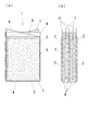
図1は、本発明の実施の形態1でのリチウムイオン二次電池の電池要素を説明する図であり、図1(a)は電池要素1の内部透視図、図1(b)は電池要素1の模式的断面図である。なお、図1(a)でのドットおよび破線の斜め線は特定の材質を示すものであり、図1(b)のハッチングは断面を表す。
(Embodiment 1)
1A and 1B are diagrams for explaining battery elements of a lithium ion secondary battery according to
電池要素1は、正極3および負極2を、それぞれ多孔質プラスチックシートのセパレータ4によって絶縁積層された構成になっている。正極3を覆ったセパレータ4は、正極3の周囲に当たる部分を、間隔を設けて融着部5において接合し袋状としている。正極3の電極活物質を塗布しない未塗布部7と、負極2の電極活物質を塗布しない未塗布部6とが互い違いになるように積層され、セパレータ4は負極2の電極活物質の未塗布部6および正極3の電極活物質の未塗布部7による略三角形の重なり部分8の間に介在する。従って、この略三角形領域で電気的に短絡することは無い。
The
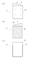
図2は電池要素の構成部材を示し、それぞれ、図2(a)は負極2、図2(b)は正極3、図2(c)はセパレータ4の形状を示す模式図であり、21は負極活物質の塗布部、31は正極活物質の塗布部である。また、図3は切断前の電極を示し、図3(a)は切断前の負極2を切断線9と共に示す模式図であり、図3(b)は切断前の正極3を切断線10と共に示す模式図である。
2A and 2B show constituent members of the battery element. FIG. 2A is a schematic view showing the shape of the
負極2と正極3は電極活物質の未塗布部6、7が切断線9、10に沿って切断されることで作製されるが、金型などで容易に切断できる。しかも直線で切断されるので、従来問題となったバリが出ること等はなく金型の調整等も容易で、負極2および正極3の生産性が向上する。
The
また、セパレータ4については、図2(c)のように、2枚の矩形シートを重ね合わせ、一定間隔に融着部5を形成することで接合するが、上方は接合せずにセパレータ開口部16を設けるように袋状に作製する。
Further, as shown in FIG. 2C, the
図4は本実施の形態でのリチウムイオン二次電池を示す内部透視図である。セパレータ4によって覆われていない領域の負極の集電体11および正極の集電体12をそれぞれ重ね合わせて接続すると共に、電池外装容器13の外へ引き出されるリード14と超音波溶着機などの溶着機を用いて電気的に接合し、セパレータおよび電極活物質には電解液を含浸させ電池外装容器13内に収容することで本発明のリチウムイオン二次電池(電池セル)15を得る。
FIG. 4 is an internal perspective view showing the lithium ion secondary battery in the present embodiment. The negative electrode
次に本実施の形態に基づいて作製した一例について説明する。負極集電体に10μmの銅箔を用い、正極集電体には20μmのアルミニウム箔を用いた。負極活物質はグラファイトを主成分とし結着剤などを加えペースト状に作製した。正極活物質には主成分としてLiMn2O4を用いたが、他にLiMnO2などのマンガン系遷移金属酸化物を用いるのもよい。これらの集電体に電極引き出し部を形成するために電極活物質未塗布部を直線状に打ち抜き切断する際、バリなどの発生による切断不良を従来例よりも低減することができた。次に、正極4枚および負極5枚を積層し、外形寸法が82×150×4mmのリチウムイオン二次電池(電池セル)を作製した。 Next, an example produced based on this embodiment will be described. A 10 μm copper foil was used for the negative electrode current collector, and a 20 μm aluminum foil was used for the positive electrode current collector. The negative electrode active material was prepared in a paste form by adding graphite as a main component and adding a binder. LiMn 2 O 4 is used as the main component for the positive electrode active material, but manganese-based transition metal oxides such as LiMnO 2 may also be used. When the electrode active material non-coated portion is punched and cut in a straight line in order to form an electrode lead-out portion in these current collectors, cutting failure due to the generation of burrs or the like can be reduced as compared with the conventional example. Next, 4 positive electrodes and 5 negative electrodes were laminated to produce a lithium ion secondary battery (battery cell) having an outer dimension of 82 × 150 × 4 mm.
(実施の形態2)
本発明の実施の形態2は電極の活物質未塗布部およびセパレータ開口部を除くと、実施の形態1と同様である。図5は本発明の実施の形態2での電池要素の構成部材を示し、図5(a)は負極の活物質未塗布部の形状を示す模式図であり、図5(b)は正極の活物質未塗布部の形状を示す模式図、図5(c)はセパレータ開口部の形状を示す模式図である。
(Embodiment 2)
The second embodiment of the present invention is the same as the first embodiment except for the electrode active material uncoated portion and the separator opening. FIG. 5 shows constituent elements of the battery element according to
セパレータ4は、図5(a)の負極2および図5(b)の正極3での電極活物質未塗布部の三角形状の重なり部分の間に介在するように電極活物質の未塗布部6、7を覆えばよいので、セパレータ開口部16の形状は、図5(c)のように、重なり部分の三角形状より少し大きい山形の形状にした。また、セパレータ4で覆わなかった電極活物質未塗布部を集電体引き出し部として用い、電極間の接続あるいは電池外装容器外への接続を行う。
The
(実施の形態3)
図6は本発明の実施の形態3での電極の活物質未塗布部の形状を示す模式図であり、図6(a)は負極の活物質未塗布部の形状を示す模式図であり、図6(b)は正極の活物質未塗布部の形状を示す模式図、図6(c)はセパレータの形状を示す模式図である。
(Embodiment 3)
FIG. 6 is a schematic diagram showing the shape of the active material uncoated portion of the electrode in
本実施の形態では、電極活物質の未塗布部6、7の形状を除くと、実施の形態1と同様である。図6のように、電極活物質の未塗布部6、7がこのような略三角形状であって、切断部が2つの直線からなるので、従来例の矩形状の場合と比べ、打ち抜き切断時のバリの発生を抑制しやすい形状である。
The present embodiment is the same as the first embodiment except for the shapes of the
上記のように本発明のリチウムイオン二次電池は、正極および負極の集電体の電極活物質未塗布部が単純な線に沿って切断される形状であり、容易に金型などで切断できる。しかも単純な線に沿って切断されるので、バリなどが出にくく金型の調整等も容易で、リチウムイオン二次電池の電池セルの生産性が向上する。 As described above, the lithium ion secondary battery of the present invention has a shape in which the electrode active material uncoated portion of the positive and negative electrode current collectors is cut along a simple line and can be easily cut with a mold or the like. . In addition, since cutting is performed along a simple line, burrs and the like are hardly generated, and the mold can be easily adjusted, and the productivity of the battery cell of the lithium ion secondary battery is improved.
上記のように作製したリチウムイオン二次電池を1つの電池セルとして、使途の電圧および電流に合わせ、直列および/または並列に接続し、保護回路、全体の制御回路などを付加することで本発明の組電池が得られる。 By connecting the lithium ion secondary battery produced as described above as one battery cell in series and / or in parallel according to the voltage and current used, and adding a protection circuit, an overall control circuit, etc., the present invention The assembled battery is obtained.
1 電池要素
2 負極
3 正極
4 セパレータ
5 融着部
6、7 未塗布部
8 重なり部分
9、10 切断線
11、12 集電体
13 電池外装容器
14 リード
15 リチウムイオン二次電池(電池セル)
16 セパレータ開口部
21、31 塗布部
DESCRIPTION OF
16
Claims (6)
前記負極および正極は集電体上の電極活物質塗布部と電極活物質未塗布部とからなり、
前記負極および正極での前記電極活物質未塗布部は、少なくとも1本または2本の直線状の切断線で切断された互いに重なり合う重なり部分と互いに重なり合わない非重なり部分とからなり、
前記多孔質プラスチックシートが前記負極および正極の両方の電極活物質塗布部を覆うように前記負極と正極の間に介在すると共に前記電極活物質未塗布部の前記重なり部分の間にも介在することを特徴とするリチウムイオン二次電池。 A negative electrode made of a negative electrode active material capable of inserting and removing lithium ions, a positive electrode made of a positive electrode active material capable of inserting and removing lithium ions, and disposed between the negative electrode and the positive electrode to insulate these electrodes In a laminated lithium ion secondary battery in which a porous plastic sheet is laminated and impregnated with an electrolytic solution,
The negative electrode and the positive electrode consist of an electrode active material application part and an electrode active material non-application part on the current collector,
The electrode active material non-applied portion at the negative electrode and the positive electrode is composed of at least one or two linear cutting lines that overlap each other and non-overlapping portions that do not overlap each other,
The porous plastic sheet is interposed between the negative electrode and the positive electrode so as to cover both of the negative electrode and positive electrode electrode active material coated portions, and is also interposed between the overlapping portions of the electrode active material uncoated portions. A lithium ion secondary battery characterized by the above.
前記負極および前記正極での電極活物質未塗布部の形状がいずれも三角形状であることを特徴とする、請求項1または2のいずれか1項記載のリチウムイオン二次電池。 The shape of the electrode active material application part in the negative electrode and the positive electrode is both rectangular ,
3. The lithium ion secondary battery according to claim 1 , wherein the electrode active material uncoated portions of the negative electrode and the positive electrode each have a triangular shape. 4.
Priority Applications (1)
| Application Number | Priority Date | Filing Date | Title |
|---|---|---|---|
| JP2007297723A JP5125438B2 (en) | 2007-11-16 | 2007-11-16 | Lithium ion secondary battery and battery pack using the same |
Applications Claiming Priority (1)
| Application Number | Priority Date | Filing Date | Title |
|---|---|---|---|
| JP2007297723A JP5125438B2 (en) | 2007-11-16 | 2007-11-16 | Lithium ion secondary battery and battery pack using the same |
Publications (2)
| Publication Number | Publication Date |
|---|---|
| JP2009123583A JP2009123583A (en) | 2009-06-04 |
| JP5125438B2 true JP5125438B2 (en) | 2013-01-23 |
Family
ID=40815511
Family Applications (1)
| Application Number | Title | Priority Date | Filing Date |
|---|---|---|---|
| JP2007297723A Active JP5125438B2 (en) | 2007-11-16 | 2007-11-16 | Lithium ion secondary battery and battery pack using the same |
Country Status (1)
| Country | Link |
|---|---|
| JP (1) | JP5125438B2 (en) |
Families Citing this family (5)
| Publication number | Priority date | Publication date | Assignee | Title |
|---|---|---|---|---|
| JP2009188115A (en) * | 2008-02-05 | 2009-08-20 | Nissan Diesel Motor Co Ltd | Electrical double-layer capacitor |
| KR101357931B1 (en) | 2011-06-16 | 2014-02-05 | 삼성에스디아이 주식회사 | Secondary battery |
| JP6244932B2 (en) * | 2014-01-21 | 2017-12-13 | 株式会社豊田自動織機 | Power storage device manufacturing apparatus and power storage device manufacturing method |
| KR101674264B1 (en) * | 2014-01-28 | 2016-11-08 | 주식회사 엘지화학 | Electrode assembly and battery sell comprising the same |
| CN113597688A (en) * | 2019-03-29 | 2021-11-02 | 株式会社村田制作所 | Solid-state battery |
Family Cites Families (2)
| Publication number | Priority date | Publication date | Assignee | Title |
|---|---|---|---|---|
| JP4293501B2 (en) * | 2001-08-24 | 2009-07-08 | Tdk株式会社 | Electrochemical devices |
| JP4932263B2 (en) * | 2005-01-28 | 2012-05-16 | Necエナジーデバイス株式会社 | Multilayer secondary battery and manufacturing method thereof |
-
2007
- 2007-11-16 JP JP2007297723A patent/JP5125438B2/en active Active
Also Published As
| Publication number | Publication date |
|---|---|
| JP2009123583A (en) | 2009-06-04 |
Similar Documents
| Publication | Publication Date | Title |
|---|---|---|
| CN110429320B (en) | Winding type battery | |
| KR101351654B1 (en) | Electrode unit and method of manufacturing the same, secondary battery having the same | |
| JP4720384B2 (en) | Bipolar battery | |
| JP5212470B2 (en) | Electrode body, all solid state battery element and all solid state battery | |
| JP6859059B2 (en) | Lithium-ion secondary battery and its manufacturing method | |
| KR101147207B1 (en) | Electrode assembly, and rechargeable battery using thereof | |
| JP2002298825A (en) | Method of producing electrochemical device and the electrochemical device | |
| JP6414898B2 (en) | Non-aqueous electrolyte secondary battery electrode, method for producing the same, and non-aqueous electrolyte secondary battery | |
| JP2012199162A (en) | Laminate covered secondary battery | |
| CN102428600B (en) | Laminated secondary battery, and method for manufacturing the laminated secondary battery | |
| JPWO2012057335A1 (en) | Prismatic secondary battery | |
| JP6270613B2 (en) | Prismatic secondary battery | |
| WO2017169130A1 (en) | Lamination type lithium ion battery | |
| JP2011076838A (en) | Laminate type battery | |
| KR102238367B1 (en) | electrode assembly and secondary battery having electrode assembly | |
| KR20200143979A (en) | Electrode assembly and secondary battery having the same | |
| JP5125438B2 (en) | Lithium ion secondary battery and battery pack using the same | |
| JPWO2014188501A1 (en) | Non-aqueous electrolyte secondary battery | |
| EP3139434B1 (en) | Coin cell and method for producing such coin cell | |
| JP2005251617A (en) | Secondary battery and battery pack | |
| KR20160129571A (en) | Electrode assembly and secondary battery comprising the same | |
| KR101387137B1 (en) | Electrode assembly and rechargeable battery with the same | |
| JP2005310577A (en) | Coin type secondary battery | |
| JP7405243B2 (en) | Current collector, power storage element and power storage module | |
| WO2024021868A1 (en) | Battery core structure and battery |
Legal Events
| Date | Code | Title | Description |
|---|---|---|---|
| A711 | Notification of change in applicant |
Free format text: JAPANESE INTERMEDIATE CODE: A712 Effective date: 20100616 |
|
| A621 | Written request for application examination |
Free format text: JAPANESE INTERMEDIATE CODE: A621 Effective date: 20101014 |
|
| A977 | Report on retrieval |
Free format text: JAPANESE INTERMEDIATE CODE: A971007 Effective date: 20120718 |
|
| A131 | Notification of reasons for refusal |
Free format text: JAPANESE INTERMEDIATE CODE: A131 Effective date: 20120803 |
|
| A521 | Request for written amendment filed |
Free format text: JAPANESE INTERMEDIATE CODE: A523 Effective date: 20120914 |
|
| TRDD | Decision of grant or rejection written | ||
| A01 | Written decision to grant a patent or to grant a registration (utility model) |
Free format text: JAPANESE INTERMEDIATE CODE: A01 Effective date: 20121005 |
|
| A01 | Written decision to grant a patent or to grant a registration (utility model) |
Free format text: JAPANESE INTERMEDIATE CODE: A01 |
|
| A61 | First payment of annual fees (during grant procedure) |
Free format text: JAPANESE INTERMEDIATE CODE: A61 Effective date: 20121015 |
|
| R150 | Certificate of patent or registration of utility model |
Free format text: JAPANESE INTERMEDIATE CODE: R150 Ref document number: 5125438 Country of ref document: JP Free format text: JAPANESE INTERMEDIATE CODE: R150 |
|
| FPAY | Renewal fee payment (event date is renewal date of database) |
Free format text: PAYMENT UNTIL: 20151109 Year of fee payment: 3 |
|
| R250 | Receipt of annual fees |
Free format text: JAPANESE INTERMEDIATE CODE: R250 |
|
| R250 | Receipt of annual fees |
Free format text: JAPANESE INTERMEDIATE CODE: R250 |
|
| R250 | Receipt of annual fees |
Free format text: JAPANESE INTERMEDIATE CODE: R250 |
|
| R250 | Receipt of annual fees |
Free format text: JAPANESE INTERMEDIATE CODE: R250 |
|
| R250 | Receipt of annual fees |
Free format text: JAPANESE INTERMEDIATE CODE: R250 |
|
| R250 | Receipt of annual fees |
Free format text: JAPANESE INTERMEDIATE CODE: R250 |