EP3967261A1 - Moules de restauration dentaire - Google Patents
Moules de restauration dentaire Download PDFInfo
- Publication number
- EP3967261A1 EP3967261A1 EP21198024.8A EP21198024A EP3967261A1 EP 3967261 A1 EP3967261 A1 EP 3967261A1 EP 21198024 A EP21198024 A EP 21198024A EP 3967261 A1 EP3967261 A1 EP 3967261A1
- Authority
- EP
- European Patent Office
- Prior art keywords
- tooth
- custom tool
- patient
- dental
- mold body
- Prior art date
- Legal status (The legal status is an assumption and is not a legal conclusion. Google has not performed a legal analysis and makes no representation as to the accuracy of the status listed.)
- Pending
Links
- 239000000463 material Substances 0.000 claims description 30
- 210000004195 gingiva Anatomy 0.000 claims description 19
- 210000003296 saliva Anatomy 0.000 claims description 9
- 239000008280 blood Substances 0.000 claims description 7
- 210000004369 blood Anatomy 0.000 claims description 7
- 238000002955 isolation Methods 0.000 claims description 5
- 239000011159 matrix material Substances 0.000 claims description 5
- 238000003801 milling Methods 0.000 claims description 5
- 238000010146 3D printing Methods 0.000 claims description 4
- 238000002604 ultrasonography Methods 0.000 claims description 2
- 238000000034 method Methods 0.000 description 59
- 238000004519 manufacturing process Methods 0.000 description 52
- 239000005548 dental material Substances 0.000 description 30
- 230000008569 process Effects 0.000 description 20
- 238000011049 filling Methods 0.000 description 18
- 238000013461 design Methods 0.000 description 16
- 230000008439 repair process Effects 0.000 description 16
- 238000000547 structure data Methods 0.000 description 13
- 230000001815 facial effect Effects 0.000 description 12
- 238000003384 imaging method Methods 0.000 description 10
- 210000004513 dentition Anatomy 0.000 description 9
- 238000002347 injection Methods 0.000 description 9
- 239000007924 injection Substances 0.000 description 9
- 230000036346 tooth eruption Effects 0.000 description 9
- 238000005266 casting Methods 0.000 description 8
- 208000002925 dental caries Diseases 0.000 description 6
- 238000010586 diagram Methods 0.000 description 6
- 238000002360 preparation method Methods 0.000 description 6
- 238000002591 computed tomography Methods 0.000 description 5
- 238000003745 diagnosis Methods 0.000 description 5
- 238000001723 curing Methods 0.000 description 4
- 238000007726 management method Methods 0.000 description 4
- 238000005498 polishing Methods 0.000 description 4
- 210000001519 tissue Anatomy 0.000 description 4
- 208000004188 Tooth Wear Diseases 0.000 description 3
- 239000003795 chemical substances by application Substances 0.000 description 3
- 238000013500 data storage Methods 0.000 description 3
- 238000000465 moulding Methods 0.000 description 3
- 238000007639 printing Methods 0.000 description 3
- 238000009877 rendering Methods 0.000 description 3
- -1 saliva Substances 0.000 description 3
- 229920000742 Cotton Polymers 0.000 description 2
- LFQSCWFLJHTTHZ-UHFFFAOYSA-N Ethanol Chemical compound CCO LFQSCWFLJHTTHZ-UHFFFAOYSA-N 0.000 description 2
- NIXOWILDQLNWCW-UHFFFAOYSA-N acrylic acid group Chemical group C(C=C)(=O)O NIXOWILDQLNWCW-UHFFFAOYSA-N 0.000 description 2
- 239000000654 additive Substances 0.000 description 2
- 230000000996 additive effect Effects 0.000 description 2
- 230000008901 benefit Effects 0.000 description 2
- 210000001124 body fluid Anatomy 0.000 description 2
- 210000000988 bone and bone Anatomy 0.000 description 2
- 238000004140 cleaning Methods 0.000 description 2
- 239000011248 coating agent Substances 0.000 description 2
- 238000000576 coating method Methods 0.000 description 2
- 238000011109 contamination Methods 0.000 description 2
- 238000005553 drilling Methods 0.000 description 2
- 239000013536 elastomeric material Substances 0.000 description 2
- 239000012530 fluid Substances 0.000 description 2
- 230000006870 function Effects 0.000 description 2
- 210000003731 gingival crevicular fluid Anatomy 0.000 description 2
- 238000003780 insertion Methods 0.000 description 2
- 230000037431 insertion Effects 0.000 description 2
- 238000012804 iterative process Methods 0.000 description 2
- 210000001847 jaw Anatomy 0.000 description 2
- 238000002595 magnetic resonance imaging Methods 0.000 description 2
- 230000003287 optical effect Effects 0.000 description 2
- 235000019271 petrolatum Nutrition 0.000 description 2
- 238000012552 review Methods 0.000 description 2
- 239000000523 sample Substances 0.000 description 2
- 239000007787 solid Substances 0.000 description 2
- 239000000243 solution Substances 0.000 description 2
- 238000003860 storage Methods 0.000 description 2
- XLYOFNOQVPJJNP-UHFFFAOYSA-N water Substances O XLYOFNOQVPJJNP-UHFFFAOYSA-N 0.000 description 2
- FHVDTGUDJYJELY-UHFFFAOYSA-N 6-{[2-carboxy-4,5-dihydroxy-6-(phosphanyloxy)oxan-3-yl]oxy}-4,5-dihydroxy-3-phosphanyloxane-2-carboxylic acid Chemical compound O1C(C(O)=O)C(P)C(O)C(O)C1OC1C(C(O)=O)OC(OP)C(O)C1O FHVDTGUDJYJELY-UHFFFAOYSA-N 0.000 description 1
- 206010010356 Congenital anomaly Diseases 0.000 description 1
- 241001024096 Uleiota Species 0.000 description 1
- 239000000853 adhesive Substances 0.000 description 1
- 230000001070 adhesive effect Effects 0.000 description 1
- 229940072056 alginate Drugs 0.000 description 1
- 229920000615 alginic acid Polymers 0.000 description 1
- 235000010443 alginic acid Nutrition 0.000 description 1
- 238000004458 analytical method Methods 0.000 description 1
- 238000009412 basement excavation Methods 0.000 description 1
- 230000015572 biosynthetic process Effects 0.000 description 1
- 230000037237 body shape Effects 0.000 description 1
- 230000008859 change Effects 0.000 description 1
- 230000001055 chewing effect Effects 0.000 description 1
- 238000004891 communication Methods 0.000 description 1
- 239000002131 composite material Substances 0.000 description 1
- 230000001054 cortical effect Effects 0.000 description 1
- 210000002455 dental arch Anatomy 0.000 description 1
- 201000002170 dentin sensitivity Diseases 0.000 description 1
- 238000005516 engineering process Methods 0.000 description 1
- 239000003822 epoxy resin Substances 0.000 description 1
- 238000005429 filling process Methods 0.000 description 1
- 238000000227 grinding Methods 0.000 description 1
- 239000002874 hemostatic agent Substances 0.000 description 1
- 239000007943 implant Substances 0.000 description 1
- 210000004283 incisor Anatomy 0.000 description 1
- 208000014674 injury Diseases 0.000 description 1
- 230000003993 interaction Effects 0.000 description 1
- 230000001788 irregular Effects 0.000 description 1
- 230000013011 mating Effects 0.000 description 1
- 238000012986 modification Methods 0.000 description 1
- 230000004048 modification Effects 0.000 description 1
- NJPPVKZQTLUDBO-UHFFFAOYSA-N novaluron Chemical compound C1=C(Cl)C(OC(F)(F)C(OC(F)(F)F)F)=CC=C1NC(=O)NC(=O)C1=C(F)C=CC=C1F NJPPVKZQTLUDBO-UHFFFAOYSA-N 0.000 description 1
- 210000002379 periodontal ligament Anatomy 0.000 description 1
- 238000000016 photochemical curing Methods 0.000 description 1
- 230000000704 physical effect Effects 0.000 description 1
- 229920000647 polyepoxide Polymers 0.000 description 1
- 238000012805 post-processing Methods 0.000 description 1
- 238000012545 processing Methods 0.000 description 1
- 230000005855 radiation Effects 0.000 description 1
- 229920005989 resin Polymers 0.000 description 1
- 239000011347 resin Substances 0.000 description 1
- 238000005070 sampling Methods 0.000 description 1
- 238000007789 sealing Methods 0.000 description 1
- 230000011218 segmentation Effects 0.000 description 1
- 239000002904 solvent Substances 0.000 description 1
- 239000004575 stone Substances 0.000 description 1
- 230000001360 synchronised effect Effects 0.000 description 1
- 230000026676 system process Effects 0.000 description 1
- 238000012360 testing method Methods 0.000 description 1
- 238000003325 tomography Methods 0.000 description 1
- 230000036347 tooth sensitivity Effects 0.000 description 1
- 230000008733 trauma Effects 0.000 description 1
- 238000012285 ultrasound imaging Methods 0.000 description 1
Images


Classifications
-
- A—HUMAN NECESSITIES
- A61—MEDICAL OR VETERINARY SCIENCE; HYGIENE
- A61C—DENTISTRY; APPARATUS OR METHODS FOR ORAL OR DENTAL HYGIENE
- A61C5/00—Filling or capping teeth
- A61C5/80—Dental aids fixed to teeth during treatment, e.g. tooth clamps
- A61C5/85—Filling bands, e.g. matrix bands; Manipulating tools therefor
-
- A—HUMAN NECESSITIES
- A61—MEDICAL OR VETERINARY SCIENCE; HYGIENE
- A61C—DENTISTRY; APPARATUS OR METHODS FOR ORAL OR DENTAL HYGIENE
- A61C13/00—Dental prostheses; Making same
- A61C13/0003—Making bridge-work, inlays, implants or the like
- A61C13/0004—Computer-assisted sizing or machining of dental prostheses
-
- A—HUMAN NECESSITIES
- A61—MEDICAL OR VETERINARY SCIENCE; HYGIENE
- A61C—DENTISTRY; APPARATUS OR METHODS FOR ORAL OR DENTAL HYGIENE
- A61C5/00—Filling or capping teeth
- A61C5/60—Devices specially adapted for pressing or mixing capping or filling materials, e.g. amalgam presses
- A61C5/62—Applicators, e.g. syringes or guns
-
- A—HUMAN NECESSITIES
- A61—MEDICAL OR VETERINARY SCIENCE; HYGIENE
- A61C—DENTISTRY; APPARATUS OR METHODS FOR ORAL OR DENTAL HYGIENE
- A61C5/00—Filling or capping teeth
- A61C5/70—Tooth crowns; Making thereof
- A61C5/77—Methods or devices for making crowns
-
- A—HUMAN NECESSITIES
- A61—MEDICAL OR VETERINARY SCIENCE; HYGIENE
- A61C—DENTISTRY; APPARATUS OR METHODS FOR ORAL OR DENTAL HYGIENE
- A61C9/00—Impression cups, i.e. impression trays; Impression methods
- A61C9/0033—Gingival retraction appliances
-
- B—PERFORMING OPERATIONS; TRANSPORTING
- B33—ADDITIVE MANUFACTURING TECHNOLOGY
- B33Y—ADDITIVE MANUFACTURING, i.e. MANUFACTURING OF THREE-DIMENSIONAL [3-D] OBJECTS BY ADDITIVE DEPOSITION, ADDITIVE AGGLOMERATION OR ADDITIVE LAYERING, e.g. BY 3-D PRINTING, STEREOLITHOGRAPHY OR SELECTIVE LASER SINTERING
- B33Y80/00—Products made by additive manufacturing
-
- A—HUMAN NECESSITIES
- A61—MEDICAL OR VETERINARY SCIENCE; HYGIENE
- A61C—DENTISTRY; APPARATUS OR METHODS FOR ORAL OR DENTAL HYGIENE
- A61C13/00—Dental prostheses; Making same
- A61C13/0003—Making bridge-work, inlays, implants or the like
- A61C13/0006—Production methods
-
- A—HUMAN NECESSITIES
- A61—MEDICAL OR VETERINARY SCIENCE; HYGIENE
- A61C—DENTISTRY; APPARATUS OR METHODS FOR ORAL OR DENTAL HYGIENE
- A61C13/00—Dental prostheses; Making same
- A61C13/0003—Making bridge-work, inlays, implants or the like
- A61C13/0022—Blanks or green, unfinished dental restoration parts
Definitions
- This disclosure relates to dental restorations.
- a dental restoration utilizes a restorative dental material used to improve function, integrity and morphology of missing or irregular tooth structure.
- a dental restoration may be used to restore missing tooth structure due to congenital discrepancies, following external trauma, or as part of a restorative treatment for dental caries, or tooth decay.
- Restorative dentistry often includes drilling decay from an infected tooth (commonly referred to as "preparing" the tooth) and then using simple tools and a high level of craftsmanship to isolate, retract, fill and contour the finished restoration. Quality isolation via a rubber dam is cumbersome and often skipped for less effective isolation via cotton roles - increasing the risk of contamination which reduces longevity of the restoration. Retraction of soft and hard tissue includes manipulation of cords, wedges and matrix bands, and imperfect technique may result in contamination, difficulty in finishing and/or polishing in interproximal areas, and poorly adapted contacts.
- Disclosed techniques include methods for dental restoration, custom tools used for dental restoration and techniques for producing custom tools for dental restoration.
- Disclosed techniques include tools providing mold cavities customized for an individual patient. In some examples, such custom tools may be produced using 3D printing techniques.
- this disclosure is directed a custom tool for forming a dental restoration in a mouth of a patient
- a one-piece mold body providing for a customized fit with at least one tooth of the patient
- the one-piece mold body including an occlusal portion forming an occlusal surface corresponding with an occlusal surface of the tooth, a mesial proximal portion forming a mesial proximal surface corresponding with a mesial proximal surface of the tooth, and a distal proximal portion forming a distal proximal surface corresponding with a distal proximal surface of the tooth.
- the mold body is configured to combine with the tooth of the patient to form a mold cavity encompassing missing tooth structure of the tooth.
- the occlusal portion, the mesial proximal portion, and the distal proximal portion are based on three-dimensional scan data of the mouth of the patient.
- this disclosure is directed a custom tool for forming a dental restoration in a mouth of a patient
- the custom tool comprising a one-piece mold body providing for a customized fit with at least one tooth of the patient, the one-piece mold body including an incisal portion corresponding with the incisal surface of the tooth, a mesial proximal portion forming a mesial proximal surface corresponding with a mesial proximal surface of the tooth, and a distal proximal portion forming a distal proximal surface corresponding with a distal proximal surface of the tooth.
- the mold body is configured to combine with the tooth of the patient to form a mold cavity encompassing missing tooth structure of the tooth.
- the incisal portion, the mesial proximal portion, and the distal proximal portion are based on three-dimensional scan data of the mouth of the patient.
- this disclosure is directed to a process of making a custom tool for forming a dental restoration of a tooth within a mouth of a patient, the process comprising obtaining three dimensional scan data of a patient's mouth, and three-dimensionally printing a custom tool for forming the dental restoration of the tooth based on the three dimensional scan data of the mouth of the patient.
- the custom tool conforms to the custom tools described in the preceding paragraphs.
- this disclosure is directed to a process of obtaining a custom tool for forming a dental restoration of a tooth within a mouth of a patient, the process comprising obtaining three dimensional scan data of a patient's mouth, transmitting at least a portion of the three dimensional scan data to a remote manufacturing facility, receiving, from the remote manufacturing facility, a custom tool for forming the dental restoration of the tooth based on the three dimensional scan data of the mouth of the patient.
- the custom tool conforms to the custom tools described in the preceding paragraphs.
- this disclosure is directed to a process of obtaining a custom tool for forming a dental restoration of a tooth within a mouth of a patient, the process comprising obtaining three dimensional scan data of a patient's mouth, transmitting at least a portion of the three dimensional scan data to a remote manufacturing facility, receiving, from the remote manufacturing facility, a design for a custom tool for forming the dental restoration of the tooth based on the three dimensional scan data of the mouth of the patient.
- the custom tool conforms to the custom tools described in the preceding paragraphs.
- Disclosed techniques include capturing a three dimensional dentition of a patient with an intraoral scanner or scanning of a conventional impression or model.
- the custom tool for a dental restoration may include a mold based on the three dimensional (3D) dentition of the patient.
- the disclosed techniques may facilitate high quality dental restorations with reduced time and skill requirements as compared to conventional dental restoration techniques.
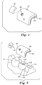
- FIGS. 1 ?? 6 illustrate custom tool 10 for forming a dental restorations of tooth 102 in a mouth of a patient.
- FIG. 1 illustrates the components of custom tool 10, including one-piece mold body 12 and plug 38.
- FIG. 2 illustrates the components of custom tool 10 as well as a portion of the mouth of a patient prior to a dental restoration.
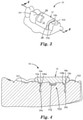
- FIG. 3 illustrates the components of custom tool 10 assembled within the mouth of a patient to facilitate a dental restoration
- FIG. 4 illustrates a cross-sectional view of FIG. 3 .
- FIG. 5 illustrates the components of custom tool 10 as well as a portion of the mouth of a patient after dental restoration with custom tool 10.
- FIG. 6 illustrates the underside of custom tool 10, which includes surfaces that correspond to various sides of tooth 102.
- custom tool 10 may represent a single tooth veneer mold and/or may be used to repair caries 104 within tooth 102.
- custom tool 10 is configured to facilitate dental restorations of a single tooth
- custom tool 10 is merely one example, and the techniques described with respect to custom tool 10 can readily be applied to custom tools that facilitate repair of two teeth or more than two teeth, e.g., by including multiple mold bodies within a single mold body component.
- Custom tool 10 includes a one-piece mold body 12, which provides a customized fit with tooth 102.
- Mold body 12 further includes optional customized surface 15a, which provides a customized fit with tooth 101 and optional customized surface 15b, which provides a customized fit with tooth 103.
- Customized surfaces 15a, 15b may further secure and register mold body 12 in place within a patient's mouth to facilitate precise customized dental restorations of tooth 102. Mold body 12 may further register with gingiva 110 of the patient.
- Custom tool 10 further includes injection port 36 for delivery of restorative dental material to the mold cavity, which may represent a veneer for tooth 102 and or repair of missing tooth structure represented by cavity 104.
- Port 36 configured to accept injection of a restorative dental material for mold cavities adjacent occlusal surfaces 18.
- occlusal surface may refer to the chewing surface of any teeth, including the posterior teeth, as well as incisal surfaces (e.g., incisal edges) of anterior teeth. In this manner, as used herein, the term occlusal surface is not indicative of any particular tooth or teeth.
- plug 38 may be positioned such that plug tip surface 39 is positioned within port 36.
- Plug 38 further includes plug tip surface 39 providing defined shapes corresponding to surfaces of repaired tooth 102.
- plug tip surface 39 may be fabricated on the basis of digital scan data.
- Custom tool 10 combines with tooth 102 to form a mold cavity of mold body 12 encompassing missing tooth structure of tooth 102 and/or a veneer for tooth 102.
- restorative dental material may be positioned into the mold cavities and take the form of the missing tooth structure of cavity 104.
- the missing tooth structure may include any portion of tooth 102, including any combination of interproximal, occlusal, facial and/or lingual tooth structure.
- An inner surface of mold body 12 each include a portion of a mold cavity corresponding with at least one exterior surface of the corresponding tooth 102, the at least exterior surface may include facial, lingual, interproximal and/or occlusal surfaces of the corresponding tooth 102.
- the mold cavities may facilitate a dental veneer restoration of facial, lingual, interproximal and/or occlusal surfaces of the corresponding tooth 102.
- Custom tool 10 may be formed based on a digital model of the teeth and mouth of a patient, which can be produced an intra-oral 3D scan, such as a multi-channel scanner.
- custom tool 10 may be digitally designed using CAD software, such as solid modeling software based on the digital model.
- Custom tool 10 was designed to fit over tooth 102 (which may represent, by way of example, a molar) and a portion of the neighboring teeth 101, 103. Subsequently, the tooth structure of teeth 101, 102, 103 may be digitally subtracted from a mold block, as well as filling port 36. Alternatively, an inverse of the tooth structure may be inverted within software to define the mold block.
- Filling port 36 may be located in regions of tooth 102 which would ultimately be removed in the preparation process, e.g., adjacent cavity 104. Filling port 36 may be sized to receive a tip of a commercially available restorative dental material compule, to permit injection of the restorative dental material during filling.
- the components within the CAD software may be converted into a 3D point mesh file or other format to facilitate production with a 3D printer, CNC mill, CAD/CAM milling processes, or otherwise.
- Orientation marks e.g., a colored mark on the distal ends of each tool component
- Production may optionally include other steps such as, curing (e.g., in a UV oven), cleaning, e.g., in alcohol solution, and/or assembly of various components, polishing of tooth surfaces, coating, such as with a clear acrylic to enhance visibility of the restoration area during injection of the restorative dental material.
- surfaces of tool components expected to be in contact with the restorative dental material could optionally be coated with a layer of release agent (e.g., a thin layer of petroleum jelly).
- FIGS. 2 ⁇ 5 illustrate steps for using the custom tool 10 to form dental restorations of tooth 102 in a mouth of a patient.
- FIG. 2 illustrates a portion of the mouth of the patient that includes teeth 101, 102, and 103 as well as gingiva 110.
- Tooth 102 includes cavity 104 in the crown of tooth 102. As shown, cavity 104 may have been caries previously prepared for the dental restoration by removing unhealthy tooth structure, e.g., by drilling or other preparation to remove damaged dental material to facilitate dental restoration using tool 10.
- a 3D image of the mouth of the patient may be taken prior to the removal of decayed material from tooth 102 as the shape of the decayed material may help in the design of custom tool 10 or the restorative procedure may be shortened by utilizing scan data obtained at a time prior to preparation of the tooth.
- the scan data may be obtained recently, such as within the past twelve months, or may be obtained a prior time, such as a period of greater than one year, greater than 5 years or even greater than 10 years ago.
- Such old scan data may demonstrate tooth wear over time and may facilitate restoration to repair such tooth wear.
- the scan data from multiple scans over time may also be used to detected tooth wear and facilitate an appropriate restoration.
- mold body 12 is positioned in place over tooth 102 such that interproximal portions 16a, 16b extend between teeth 101, 102, 103. Mold body 12 provides a customized and secure placement within the mouth of the patient. In various examples, depending on the design of custom tool 10, mold body 12 may be positioned on the lingual, occlusal and/or facial sides of tooth 102.
- restorative dental material 112 is positioned within the mold cavity formed by tooth 102 and mold body 12. Because the tooth preparations may prepared at a depth greater than the recommended maximum cure depth for the restorative dental material, or a different shade, viscosity or other property of restorative material is desired at deeper layers of the cavity, a base layer of restorative dental material can optionally be layered into the deep portions of the preparation and restorative dental material photocured, e.g., with an XL 3000 curing light.
- the components of tool 10, including mold body 12 and plug 38, may be transparent or translucent to facilitate photocuring. In such examples, restorative dental material 112 represents more than one layer of restorative dental material.
- mold body 12 is removed from the mouth of the patient. As shown in FIG. 5 , cavity 104 is now filled and the shape of the filling matches the occlusal surface of tooth 102. In this manner, mold body 12 not only provides a customized fit with the mouth of the patient, but also provides a customized mold cavity to facilitate repair of missing tooth structure of tooth 102 and/or application of a veneer to tooth 102.
- one-piece mold body 12 includes customized surfaces for each of teeth 101, 102, 103.
- surface 15a is customized to fit with tooth 101
- surface 13 is customized to fit with tooth 102
- surface 15b is customized to fit with tooth 103.
- Surface 13 provides a customized fit for more than one surface of tooth 102.
- surface 13 includes occlusal surface 32 corresponding with an occlusal surface of tooth 102, distal proximal surface 35 corresponding with a distal proximal of tooth 102, mesial proximal surface 31 corresponding with a mesial proximal of tooth 102, facial surface 34 corresponding with a facial surface of tooth 102 and lingual surface 33 corresponding to a lingual surface of tooth 102.
- Each of the areas of surface 13 of mold body 12 may be based on three-dimensional scan data of the mouth of the patient, as well as computerized design of a dental restoration of tooth 102.
- Distal proximal surface 35 corresponding with a distal proximal of tooth 102, mesial proximal surface 31 corresponding with a mesial proximal of tooth 102 and lingual surface 33 corresponding to a lingual surface of tooth 102 may represent wrap portions of one-piece mold body 12 in that these areas of mold body 12 may engage with the lingual surface of tooth 102 to allow the custom tool 10 to snap onto tooth 102 to facilitate precise positioning of custom tool 10 on tooth 102.
- port 36 is optionally positioned adjacent occlusal surface 32 and facial surface 34. While the location of port 36 may be adjusted according to the location of the mold cavity placing port 36 on adjacent occlusal surface 32 and/or facial surface 34 may generally facilitate easier access by a practitioner during a dental restoration procedure than at other positions. The location of the port 36 can also be prescribed by the doctor prior to design of the mold 12 as an area targeted for build-up of excess material or excavation of undesired tooth structure.
- the customized fit of mold body 12 may further serve to isolate tooth 102 from blood, gingival crevicular fluid, or saliva during a dental restoration material.
- portions of mold body 12 may mate with surfaces of teeth 101, 102, 103 as well as gingiva 110 to shield the mold cavity from bodily fluids such as blood, gingival crevicular fluid, and saliva.
- mold body 12 may further serve to forcibly retract gingiva 110 and/or assisting in separating teeth 101, 102, 103 upon insertion of mold body 12 within the mouth of the patient.
- interproximal portions 16a, 16b of mold body 12 may serve to forcibly separate adjacent teeth 101, 102, 103.
- custom tool 10 may be based on a three-dimensional model of the mouth of a patient, various features of custom tool 10 may be selected to temporarily modify the positions of gingiva 110 and/or teeth 101, 102, 103 during a restoration procedure.
- mold body 12 may be further configured to provide features, including customized gingival surfaces representing an isolation matrix for a dental restoration.
- mold body 12 may contain features that extend subgingivally or into a hidden interproximal space.
- the data for these extensions can be based off of anatomical averages, or patient specific data, such as x-ray, ultrasound, or MRI.
- the tool may incorporate elastomeric material which can be designed for an undersized fit to create a tight seal against varying actual geometry of the patient's dentition.
- the materials used may also vary in hydrophilicity to draw water, saliva, and other fluids away from the tooth structure being restored. Microfluidic channels, vacuum line attachments and bite blocks can be incorporated as well.
- custom tool 10 including one-piece mold body 12 is described with respect to a single mold cavity for repair of a single tooth 102, the techniques described with respect to custom tool 10 may easily be applied to a custom tool configured to facilitate repair of more than one tooth by forming more than one mold cavity.
- the modified custom tool 10 may include a one-piece mold body including a second occlusal portion forming a second occlusal surface corresponding with a second occlusal surface of an adjacent tooth, such as tooth 101, a second mesial proximal portion forming a second mesial proximal surface corresponding with a second mesial proximal surface of the adjacent tooth, and a second distal proximal portion forming a second distal proximal surface corresponding with a second distal proximal surface of the adjacent tooth.
- the one-piece mold body of the modified custom tool 10 may be configured to combine with the two adjacent teeth, (e.g., 101 and 102) to form separate mold cavities encompassing missing tooth structure for each of the adjacent teeth.
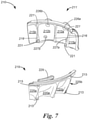
- FIGS. 7 ⁇ 9 illustrate an alternative custom tool 210 for forming dental restorations of two adjacent teeth 120a, 120b (collectively, "teeth 120") in a mouth of a patient.
- FIG. 7 illustrates the components of custom tool 210, including one-piece mold body component 211 and support member 219.
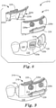
- FIG. 8 illustrates the components of custom tool 210 as well as a portion of the mouth of a patient.
- FIG. 9 illustrates the components of custom tool 210 assembled within the mouth of a patient to facilitate a dental restoration. While custom tool 210 is configured to facilitate dental restorations of two adjacent teeth, custom tool 210 is merely one example, and the techniques described with respect to custom tool 210 can readily be applied to custom tools that facilitate repair of a single tooth or more than two teeth.
- Custom tool 210 includes one-piece mold body component 211, which includes first mold body 212a and second mold body 212b (collectively, “mold bodies 212"). Mold bodies 212 each provide a customized fit with at least one tooth of the patient. As shown in FIG. 8 , mold body 212a provides a customized fit with tooth 120a, and mold body 212b provides a customized fit with tooth 120b. Mold body component 211 further includes optional customized surface 215a, which provides a customized fit with tooth 126 and optional customized surface 215b, which provides a customized fit with tooth 128. Customized surfaces 215a, 215b may further secure and register mold bodies 212 in place within a patient's mouth to facilitate precise customized dental restorations of teeth 120. Mold body component 211 may further register with gingiva 110 of the patient.
- mold bodies 212 may be further configured to provide features, including customized gingival surfaces representing an isolation matrix for a dental restoration.
- mold bodies 212 may contain features that extend subgingivally or into hidden interproximal space.
- the data for these extensions can be based off of anatomical averages, or patient x-ray data.
- the tool may incorporate elastomeric material which can be designed for an undersized fit to create a tight seal against varying actual geometry of the patient's dentition.
- the materials used may also vary in hydrophillicity to draw water, saliva, and other fluids away from the tooth structure being restored. Microfluidic channels, vacuum line attachments and bite blocks can be incorporated as well.
- mold bodies 212 may further serve to isolate teeth 120 from blood or saliva during a dental restoration material.
- portions of mold bodies 212 may mate with surfaces of teeth 120, 126, 128 as well as gingiva 110 to shield the mold cavity from bodily fluids such as blood and saliva.
- mold bodies 212 may further serve to forcibly retract gingiva 110 and/or separate teeth 120, 126, 128 upon insertion of mold body component 211 within the mouth of the patient.
- interproximal portions 216 of mold bodies 212 may serve to forcibly separate adjacent teeth.
- custom tool 210 may be based on a three-dimensional model of the mouth of a patient, various features of custom tool 210 may be selected to temporarily modify the positions of gingiva 110 and/or teeth 120, 126, 128 during a restoration procedure.
- Custom tool 210 further includes optional support body component 219.
- Support body component 219 includes first support body 220a and second support body 220b (collectively, “support bodies 220"), which are engageable with, and provide support for, mold bodies 212 via snap fit connections.
- support bodies 220 may not provide any portion of the mold cavities, but may instead simply help secure mold body component 211 including mold bodies 212 in place.
- Support bodies 220 include snap fit elements 221 that mate with corresponding snap fit elements 213 of mold bodies 212.
- Both mold body component 211 and support body component 219 may include surfaces that register with the teeth of the patient, as well as gingiva 110 of the patient.
- mold body 212a may include features that register with tooth 120 and tooth 126
- mold body 212b may include features that register with tooth 120 and tooth 128.
- support body 220a may include features that register with tooth 120 and tooth 126
- support body 220b may include features that register with tooth 120 and tooth 128.
- Support body component 219 further includes optional customized surface 225a, which provides a customized fit with tooth 126 and optional customized surface 225b, which provides a customized fit with tooth 128.
- Customized surfaces 225a, 225b may further secure and register mold bodies 212 in place within a patient's mouth to facilitate precise customized dental restorations of teeth 120.
- Support body component 219 may further register with gingiva 110 of the patient.
- mold bodies 212 and support bodies 220 may provide multiple customized surfaces that mate with corresponding surfaces of teeth 120, 126, 128 as well as gingiva 110 of the patient.
- the combination of mold body component 211 and support body component 219 provides a secure fit within the mouth of the patient to precisely align mold bodies 212 with teeth 120 in order to facilitate dental restorations of teeth 120.
- support bodies 220 are described as not forming any portion of mold cavity, in other examples, the support bodies 220 may be readily modified to combine with mold bodies 212 to form one or more mold cavities. In such examples, the modified support bodies 220 should also be considered mold bodies.
- Mold bodies 212 further include injection ports 226a, 226b (collectively, “ports 226") for delivery of restorative dental material to mold cavities. Ports 226 are configured to accept injection of a restorative dental material for mold cavities adjacent teeth 120. Mold bodies 212 further include vent ports 227a, 227b (collectively, “vent ports 227”) to allow air and excess dental material to escape the mold cavities as material is injected via fill ports 226.
- ports 226a, 226b for delivery of restorative dental material to mold cavities.
- Ports 226 are configured to accept injection of a restorative dental material for mold cavities adjacent teeth 120.
- Mold bodies 212 further include vent ports 227a, 227b (collectively, “vent ports 227”) to allow air and excess dental material to escape the mold cavities as material is injected via fill ports 226.
- Custom tool 210 combines with teeth 120 to form two distinct mold cavities of mold bodies 212.
- Mold cavities of mold bodies 212 encompass missing tooth structures 121a, 121b (collectively, "tooth structures 121") of teeth 120 and/or a veneer for one or both of teeth 120.
- teeth structures 121 are missing tooth structures 121a, 121b (collectively, "tooth structures 121" of teeth 120 and/or a veneer for one or both of teeth 120.
- restorative dental material may be positioned into the mold cavities and take the form of tooth structures 121 and/or provide a veneer on the surfaces of teeth 120.
- Missing tooth structures 121 may include any portion of teeth 120, including any combination of interproximal, occlusal, facial and/or lingual tooth structure, although in the example of FIGS. 7 ⁇ 9, the missing tooth structures 121 are depicted on the facial side of teeth 120.
- An inner surface of mold bodies 212 each include a portion of a mold cavity corresponding with at least one exterior surface of the corresponding tooth 120, the at least exterior surface may include facial, lingual, interproximal and/or occlusal surfaces of the corresponding tooth 120.
- the mold cavities may facilitate dental veneer restoration of facial, lingual, interproximal and/or occlusal surfaces of the corresponding tooth 120.
- Custom tool 210 may be formed based on a digital model of the teeth and mouth of a patient, which can be produced an intra-oral 3D scan, such as a multi-channel scanner.
- custom tool 210 may be digitally designed using CAD software, such as solid modeling software based on the digital model.
- Custom tool 210 was designed to fit over teeth 120 (which may represent, by way of example, adjacent incisors) and a portion of the neighboring teeth 126, 128. Subsequently, the tooth structure of teeth 120, 126, 128 may be digitally subtracted from a mold block, as well as filling ports 226 and optional vent ports 227. Alternatively, an inverse of the tooth structure may be inverted within software to define the mold block.
- Filling ports 226 may be located in regions of the occlusal section which correspond to regions of the teeth which would ultimately be removed in the preparation process, e.g., adjacent to the mold cavities of teeth 120. Filling ports 226 may be sized to receive a tip of a commercially available restorative dental material compule, to permit injection of the restorative dental material during filling. Vent ports 227 may be sized smaller in diameter than filling ports 226.
- the mold block design may be segmented into two sections (mold body component 211 and support body component 219) to facilitate eventual assembly of the tool components on the teeth without geometric interference.
- handle features 229 may be included added to mold body component 211 and support body component 219 to facilitate holding of the portions with a hemostat or cotton pliers during dental restoration using tool 210.
- the components within the CAD software may be converted into a 3D point mesh file or other format to facilitate production with a 3D printer, CNC mill, CAD/CAM milling processes, or otherwise.
- Orientation marks e.g., a colored mark on the distal ends of each tool component
- Production may optionally include other steps such as, curing (e.g., in a UV oven), cleaning, e.g., in alcohol solution, and/or assembly of various components, polishing of tooth surfaces, coating, such as with a clear acrylic to enhance visibility of the restoration area during injection of the restorative dental material.
- surfaces of tool components expected to be in contact with the restorative dental material could optionally be coated with a layer of release agent (e.g., a thin layer of petroleum jelly).
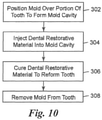
- FIG. 10 is a flowchart illustrating an example technique for forming a dental restoration in a mouth of a patient.
- a practitioner positions a mold, such as mold body 12 or mold body component 211, over a portion of a tooth of the patient (302).
- the tooth either contains missing tooth structure or has been prepared to create missing tooth structure, such as is commonly done in the caries removal process.
- the mold combines with the tooth to form a mold cavity encompassing missing tooth structure of the tooth.
- a practitioner injects a restorative dental material within the mold cavity (304).
- the practitioner allows the restorative dental material to cure within the mold cavity to reform the tooth, which may include application of actinic radiation to cure the restorative dental material (306).
- the practitioner removes the mold from the tooth of the patient leaving the dental restoration with a shape defined by the mold cavity on the tooth of the patient (308).
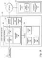
- FIG. 11 is a block diagram illustrating an example computer environment 340 in which clinic 344 and manufacturing facility 348 communicate information throughout a manufacturing process of custom tool 10 and/or custom tool 210 for patient 342.
- an dental practitioner of clinic 344 generates one or more images of a dental structure of patient 342 using any suitable imaging technique and generates digital dental structure data 346 (e.g., a digital representation of patient's 342 tooth structure and, optionally, mouth tissues such as gingiva 110).
- the practitioner may generate X-RAY images that can be digitally scanned.
- the practitioner may capture digital images of the patient tooth structure using, for example, conventional computed tomography (CT), laser scanning, intra-oral scanning, CT scans of dental impressions, scans of dental casts poured from impressions, ultrasound instrumentation, magnetic resonance imaging (MRI), or any other suitable method of 3D data acquisition.
- CT computed tomography
- MRI magnetic resonance imaging
- the digital images may be provided using a hand-held intra-oral scanner such as the intra-oral scanner using active wavefront sampling developed by Brontes Technologies, Inc. (Lexington, MA) and described in PCT Publication No. WO 2007/084727 (Boerjes, et al. ), which is incorporated by reference herein.
- other intra-oral scanners or intra-oral contact probes may be used.
- the digital structure data 346 may be provided by scanning a negative impression of the patient's teeth.
- the digital structure data 346 may be provided by imaging a positive physical model of the patient's teeth or by using a contact probe on a model of the patient's teeth.
- the model used for scanning may be made, for example, by casting an impression of a patient's dentition from a suitable impression material such as alginate or polyvinylsiloxane (PVS), pouring a casting material (such as dental stone or epoxy resin) into the impression, and allowing the casting material to cure.
- a suitable impression material such as alginate or polyvinylsiloxane (PVS)
- PVS polyvinylsiloxane
- Any suitable scanning technique may be used for scanning the model, including those described above. Other possible scanning methods are described in U.S. Patent Publication No. 2007/0031791 (Cinader et al. ), which is incorporated by reference herein.
- the digital tooth structure data is formed by providing several 3D images of these features and subsequently "stitching" them together. These different images need not be provided using the same imaging technique.
- a digital image of teeth roots provided with a CT scan may be integrated with a digital image of the teeth crowns provided with an intraoral visible light scanner. Scaling and registering of 2D dental images with 3D dental images is described in U.S. Patent No. 6,845,175 (Kopelman, et al. ), which is incorporated by reference herein, and U.S. Patent Publication No.
- the dental structure may include, but is not limited to, any portion of crowns and/or roots of one or more teeth of a dental arch, gingiva, periodontal ligaments, alveolar bone, cortical bone, implants, artificial crowns, bridges, veneers, dentures, dental appliances, or any structure that could be considered part of the dentition before, during, or after treatment.
- a computer In order to generate digital tooth structure data 346, a computer must transform raw data from the imaging systems into usable digital models. For example, for raw data representing the shapes of teeth received by a computer, the raw data is often little more than a point cloud in 3D space. Typically, this point cloud is surfaced to create 3D object models of the patient's dentition, including one or more teeth, gingival tissue, and other surrounding oral structure.
- the computer may "segment" dentition surfaces to produce one or more discrete, movable 3D tooth object models representing individual teeth. The computer may further separate these tooth models from the gingiva into separate objects. Segmentation allows a user to characterize and manipulate the teeth arrangement as a set of individual objects.
- clinic 344 may store digital dental structure data 346 within a patient record in a database.
- Clinic 344 may, for example, update a local database having a plurality of patient records.
- clinic 344 may remotely update a central database (optionally within manufacturing facility 348) via network 350.
- clinic 344 electronically communicates digital dental structure data 346 to manufacturing facility 348.
- manufacturing facility 348 may retrieve digital dental structure data 346 from the central database.
- Clinic 344 may also forward treatment data 347 conveying general information regarding a practitioner's diagnosis and treatment plan for patient 342 to manufacturing facility 348.
- treatment data 347 may be more specific.
- digital dental structure data 346 may be a digital representation of the dental structure of patient 342, and the practitioner of clinic 344 may review the digital representation and indicate desired repairs, including locations for veneers, crowns or fillings for individual teeth of patient 342 prior to forwarding digital dental structure data 346 to manufacturing facility 348.
- the doctor and manufacturing facility may also engage in an iterative process to arrive at the proper treatment plan. Such interactions may be facilitated by digital communication such as via the Treatment Management Portal offered by 3M Oral Care.
- Manufacturing facility 348 may be located off-site, or located with clinic 344.
- each clinic 344 may include its own equipment for manufacturing facility 348 such that a treatment plan and digital design may be performed entirely by a clinical practitioner, or an assistant, in the clinical setting, using software installed locally
- the manufacturing may be performed in the clinic, as well, by using a 3D printer (or by other methods of additive manufacturing).
- a remote manufacturing facility may process the three dimensional scan data of a patient and produce a digital model of a design for a custom tool for forming the dental restoration of the tooth based on the three dimensional scan data of the mouth of the patient. The remote manufacturing facility may then return the digital model of a design for a custom tool for forming the dental restoration of the tooth to the clinic 344.
- a 3D printer allows manufacturing of intricate features of a custom tool or a physical representation of the dental structure of patient 342 through additive printing.
- the 3D printer may use iterative digital designs of original dental structure of patient 342 as well as a desired dental structure of patient 342 to produce multiple custom tools and/or custom tool patterns customized to produce the desired dental structure of patient 342.
- Manufacturing may include post-processing to remove uncured resin and remove support structures, or to assemble various components, which may also be necessary and could also be performed in a clinical setting.
- manufacturing can be performed by subtractive manufacturing, such as CAD/CAM mills.
- Manufacturing facility 348 utilizes digital dental structure data 346 of patient 342 to construct custom tool 10 and/or custom tool 210 in order to repair teeth of patient 342. Sometime thereafter, manufacturing facility 348 forwards custom tool 10 and/or custom tool 210 to clinic 344.
- FIG. 12 is a flow diagram illustrating process 360 conducted at clinic 344 in accordance with one example of this disclosure.
- a practitioner at clinic 344 collects patient identity and other information from patient 342 and creates a patient record (362).
- the patient record may be located within clinic 344 and optionally configured to share data with a database within manufacturing facility 348.
- the patient record may be located within a database at manufacturing facility 348 that is remotely accessible to clinic 344 via network 350 or within a database that is remotely accessible by both manufacturing facility 348 and clinic 344.
- digital data 346 of the dental structure of patient 342 may be generated using any suitable technique (364), to thereby create a virtual dental structure.
- Digital data 346 may be comprised of a two-dimensional (2D) image and/or a three-dimensional (3D) representation of the dental structure.
- 3D representations of a dental structure are generated using a cone beam computerized tomography (CBCT) scanner, such as an i-CAT 3D dental imaging device, which is available from Imaging Sciences International, LLC; 1910 N Penn Road, Hatfield, PA.
- Clinic 344 stores the 3D data 346 (in the form of radiological images) generated from the CBCT scanner in the database located within clinic 344, or alternatively, within manufacturing facility 348.
- the computing system processes the digital data 346 from the CBCT scanner, which may be in the form of a plurality of slices, to compute a digital representation of the tooth structure that may be manipulated within the 3D modeling environment.
- the practitioner may further generate 3D digital data (366).
- the 3D data 346 may be produced by, for example, forming and subsequently digitally scanning a physical impression or casting of the tooth structure of patient 342.
- a physical impression or casting of teeth of patient 342 may be scanned using a visible light scanner, such as an OM-3R scanner available from Laser Design, Inc. of Minneapolis, MN.
- the practitioner may generate the 3D data 346 of the occlusal service by use of an intra-oral scan of the teeth of patient 342, or existing 3D tooth data.
- 2D radiological images and the 3D digital data for the occlusal surface of the teeth are registered by first attaching registration markers (e.g., fiducial markers or a pedestal having known geometry) to the tooth structure of patient 342 prior to generating both the radiological images and the 3D digital scan. Thereafter, the digital representation of the registration markers within the 2D radiological image and the 3D digital data may be aligned within a 3D modeling environment using registration techniques described in U.S. Patent No. 8,491,306 .
- registration markers e.g., fiducial markers or a pedestal having known geometry
- 3D digital data of the tooth structure is generated by combining two 3D digital representations of the tooth structure.
- a first 3D digital representation may be a relatively low resolution image of the roots obtained from a CBCT scanner (e.g., an i-CAT 3D dental imaging device) and the second 3D digital representation may be a relatively high resolution image of the crowns of the teeth obtained from an industrial CT scan of an impression or a visible light (e.g., laser) scan of a casting of the teeth of the patient.
- the 3D digital representations may be registered using a software program that enables the 3D representations to be manipulated within a computer environment (e.g., Geomagic Studio software, available from 3D Systems, Inc.; 333 Three D Systems Circle, Rock Hill, SC), or alternatively, registration techniques described in U.S. Patent No. 8,491,306 may be used.
- a software program that enables the 3D representations to be manipulated within a computer environment
- Geomagic Studio software available from 3D Systems, Inc.
- 333 Three D Systems Circle, Rock Hill, SC Three D Systems Circle, Rock Hill, SC
- registration techniques described in U.S. Patent No. 8,491,306 may be used.
- a computer system executing 3D modeling software renders a resultant digital representation of the tooth structure, including the occlusal surface, and, optionally, the root structure of the patient's teeth.
- Modeling software may provide a user interface that allows the practitioner to manipulate digital representations of the teeth in 3D space relative to the digital representation of the patient's teeth.
- the practitioner By interacting with the computer system, the practitioner generates treatment information, such as by selecting areas of repair of the teeth of patient 342 (367).
- the computer system updates the database associated with the patient record to record the treatment data 347 conveying general information regarding a diagnosis and treatment plan as specified by the practitioner (368). Thereafter, the treatment data 347 is relayed to manufacturing facility 348 in order for manufacturing facility 348 to construct one or more custom tools, such as custom tool 10 and/or custom tool 210 (370).
- one or more of the steps discussed with respect to FIG. 12 may be performed by a remote user, such as a user located at manufacturing facility 348.
- the dental practitioner may only send radiological image data and an impression or casting of the patient to manufacturing facility 348, where a user interacts with a computer system to develop a treatment plan within a 3D modeling environment.
- a digital representation of the treatment plan within the 3D modeling environment may then be transmitted to the dental practitioner of clinic 344, who may review the treatment plan and either send back his or her approval, or indicate desired changes.
- An additional option would be for the manufacturing facility to create the digital design of the tool which is then returned to the clinic for production on system in the clinic (e.g. 3D printer or mill).
- FIG. 13 is a block diagram illustrating an example of a client computing device 380 connected to manufacturing facility 348 via network 350.
- client computing device 380 provides an operating environment for modeling software 382.
- Modeling software 382 presents a modeling environment for modeling and depicting the 3D representation of the teeth of patient 342.
- modeling software 382 includes user interface 384, mold cavity module 386, and rendering engine 388.
- User interface 384 provides a graphical user interface (GUI) that visually displays the 3D representation of patient 342's teeth.
- GUI graphical user interface
- user interface 384 provides an interface for receiving input from practitioner 389 of clinic 344 ( FIG. 11 ), e.g., via a keyboard and a pointing device, for manipulating patient 342's teeth within the model, e.g., to select portions for repair, and/or adjust the surfaces of a mold cavity that define the exterior repaired surface of patient 342's teeth as provided by custom tool 10 and/or custom tool 210.
- Modeling software 382 may be accessible to manufacturing facility 348 via network interface 381. Modeling software 382 interacts with database 390 to access a variety of data, such as treatment data 392, 3D data 394 relating to the tooth structure of patient 342, and patient data 396.
- Database 390 may be represented in a variety of forms including data storage files, lookup tables, or a database management system (DBMS) executing on one or more database servers.
- the database management system may be a relational (RDBMS), hierarchical (HDBMS), multi-dimensional (MDBMS), object oriented (ODBMS or OODBMS) or object relational (ORDBMS) database management system.
- the data may, for example, be stored within a single relational database, such as SQL Server from Microsoft Corporation.
- database 390 may be located remote from the client computing device and coupled to the client computing device via a public or private network, e.g., network 350.
- Treatment data 392 describes a diagnosis and or repair information of the teeth of patient 342 selected by practitioner 389 and positioned within the 3D modeling environment.
- Patient data 396 describes a set of one or more patients, e.g., patient 342, associated with practitioner 389.
- patient data 396 specifies general information, such as a name, birth date, and a dental history, for each patient.
- Rendering engine 388 accesses and renders 3D data 394 to generate the 3D view presented to practitioner 389 by user interface 384. More specifically, 3D data 394 includes information defining the 3D objects that represent each tooth (optionally including roots), and jaw bone within the 3D environment. Rendering engine 388 processes each object to render a 3D triangular mesh based on viewing perspective of practitioner 389 within the 3D environment. User interface 384 displays the rendered 3D triangular mesh to practitioner 389, and allows practitioner 389 to change viewing perspectives and manipulate objects within the 3D environment.
- Client computing device 380 includes processor 383 and memory 385 in order to store and execute modeling software 382.
- Memory 385 may represent any volatile or non-volatile storage elements. Examples include random access memory (RAM) such as synchronous dynamic random access memory (SDRAM), read-only memory (ROM), non-volatile random access memory (NVRAM), electrically erasable programmable read-only memory (EEPROM), and FLASH memory. Examples may also include non-volatile storage, such as a hard-disk, magnetic tape, a magnetic or optical data storage media, a compact disk (CD), a digital versatile disk (DVD), a Blu-ray disk, and a holographic data storage media.
- RAM random access memory
- SDRAM synchronous dynamic random access memory
- ROM read-only memory
- NVRAM non-volatile random access memory
- EEPROM electrically erasable programmable read-only memory
- FLASH memory FLASH memory
- non-volatile storage such as a hard-disk, magnetic tape, a magnetic or
- Processor 383 represents one or more processors such as a general-purpose microprocessor, a specially designed processor, an application specific integrated circuit (ASIC), a field programmable gate array (FPGA), a collection of discrete logic, or any type of processing device capable of executing the techniques described herein.
- memory 385 may store program instructions (e.g., software instructions) that are executed by processor 383 to carry out the techniques described herein.
- the techniques may be executed by specifically programmed circuitry of processor 383. In these or other ways, processor 383 may be configured to execute the techniques described herein.
- Client computing device 380 is configured to send a digital representation of a 3D tooth structure of a patient, and optionally, treatment data 392 and/or patient data 396 to computer 370 of manufacturing facility 348 via network 350.
- Computer 370 includes user interface 372.
- User interface 372 provides a GUI that visually displays the 3D representation of the digital model of teeth.
- user interface 372 provides an interface for receiving input from a user, e.g., via a keyboard and a pointing device, for manipulating a patient's teeth within the digital representation of the 3D tooth structure of the patient.
- Computer 370 may further be configured to determine dimensions and shapes a custom tool, the dimensions and shapes of the custom tool being configured to provide one or more mold bodies and mold cavities repair the one or more teeth of the patient. Computer 370 may provide the dimensions and shapes of the custom tool to automated manufacturing system 374 for production of the custom tool.
- Client computing device 380 and computer 370 are merely conceptual representations of an example computer system.
- the functionalities described with respect to of client computing device 380 and/or computer 370 may be combined into a single computing device or distributed among multiple computing devices within a computer system.
- cloud computing may be used for digital design of custom tools described herein.
- the digital representations of tooth structures are received at one computer at the clinic, while a different computer, such as computer 370, is used to determine the shapes and dimensions of a custom tool.
- Shapes and dimensions may be determined, at least in part, based on knowledge derived through analysis of historical cases or virtual models of exemplary cases, without receiving a complete 3D representation of the case in question.
- data transmitted between client computing device 380 and computer 370, or otherwise utilized to design a custom tool may be significantly less than the complete data set representing a complete digital dental model of a patient.
- custom tools can be fabricated off of initial tooth geometry or digitally optimized tooth geometry (e.g. hole filling close gaps in the data, pulling and scaling data from tooth libraries, testing in a virtual articulator). Tools can fit precisely to the existing structure or can be optimized to selectively move or position tissue. Custom tools can be formed without prior information of the where the tooth structure will be removed, such as when the extent of caries is not known. Custom tools may be formed to generate a digitally optimized tooth structure that will require the practitioner to remove tooth structure prior to application of the tool. Tools can be printed or milled. Tools can be made from the full range of 3D printed materials (strength, flexibility, translucency, color).
- Tools can be coated with a range of agents to optimize release, surface finish and optical transparency. Tools can contain features to indicate or define fill level of different restorative materials (shade, fill level, physical properties). Physical characteristics (elasticity, roughness,,transparency, etc) of tools can vary across the tool to sealing capability, dimensional fidelity, texture imparted to restorative material, degree of cure of material, etc). Tools / mold sections can interlock with each other or with standard components (e.g. matrix bands). Tools can be used inside or outside of the mouth. Restorative material can be injected through ports in tools, applied to tooth structure and/or tool prior to the application of the tool, such that application shapes the material. Tools can be degradable (e.g.
- Kits can be created of the patient specific tools and associated products and quantities, (e.g. adhesives, filling, and polishing materials selected for the patient needs and/or doctor preferences). Series of tools used sequentially in the direct filling process in order to control the geometries of multiple layers of a dental restoration on a tooth.
- Dental scans may be taken at diagnostic appointment to facilitate custom tools fabrication prior to a dental restoration appointment. Tools may be manufactured locally or digital scan data may be sent to a remote location for production.
Landscapes
- Health & Medical Sciences (AREA)
- Oral & Maxillofacial Surgery (AREA)
- Dentistry (AREA)
- Epidemiology (AREA)
- Life Sciences & Earth Sciences (AREA)
- Animal Behavior & Ethology (AREA)
- General Health & Medical Sciences (AREA)
- Public Health (AREA)
- Veterinary Medicine (AREA)
- Chemical & Material Sciences (AREA)
- Engineering & Computer Science (AREA)
- Manufacturing & Machinery (AREA)
- Materials Engineering (AREA)
- Dental Tools And Instruments Or Auxiliary Dental Instruments (AREA)
- Dental Prosthetics (AREA)
Applications Claiming Priority (3)
| Application Number | Priority Date | Filing Date | Title |
|---|---|---|---|
| US201562268551P | 2015-12-17 | 2015-12-17 | |
| EP16820514.4A EP3389552B1 (fr) | 2015-12-17 | 2016-12-15 | Moules de restauration dentaire monoblocs |
| PCT/US2016/066777 WO2017106419A1 (fr) | 2015-12-17 | 2016-12-15 | Moules de restauration dentaire monoblocs |
Related Parent Applications (1)
| Application Number | Title | Priority Date | Filing Date |
|---|---|---|---|
| EP16820514.4A Division EP3389552B1 (fr) | 2015-12-17 | 2016-12-15 | Moules de restauration dentaire monoblocs |
Publications (1)
| Publication Number | Publication Date |
|---|---|
| EP3967261A1 true EP3967261A1 (fr) | 2022-03-16 |
Family
ID=57708846
Family Applications (2)
| Application Number | Title | Priority Date | Filing Date |
|---|---|---|---|
| EP16820514.4A Active EP3389552B1 (fr) | 2015-12-17 | 2016-12-15 | Moules de restauration dentaire monoblocs |
| EP21198024.8A Pending EP3967261A1 (fr) | 2015-12-17 | 2016-12-15 | Moules de restauration dentaire |
Family Applications Before (1)
| Application Number | Title | Priority Date | Filing Date |
|---|---|---|---|
| EP16820514.4A Active EP3389552B1 (fr) | 2015-12-17 | 2016-12-15 | Moules de restauration dentaire monoblocs |
Country Status (7)
| Country | Link |
|---|---|
| US (2) | US11185392B2 (fr) |
| EP (2) | EP3389552B1 (fr) |
| JP (1) | JP6971235B2 (fr) |
| CN (1) | CN108366848A (fr) |
| AU (1) | AU2016370731B2 (fr) |
| ES (1) | ES2893954T3 (fr) |
| WO (1) | WO2017106419A1 (fr) |
Families Citing this family (26)
| Publication number | Priority date | Publication date | Assignee | Title |
|---|---|---|---|---|
| JP6678671B2 (ja) | 2014-12-09 | 2020-04-08 | スリーエム イノベイティブ プロパティズ カンパニー | 歯科修復物成形技術 |
| JP6878436B2 (ja) | 2015-12-17 | 2021-05-26 | スリーエム イノベイティブ プロパティズ カンパニー | 歯科修復物用モールド |
| EP3389552B1 (fr) | 2015-12-17 | 2021-09-22 | 3M Innovative Properties Company | Moules de restauration dentaire monoblocs |
| EP3490487B1 (fr) | 2016-07-26 | 2021-09-01 | 3M Innovative Properties Company | Moules de restauration dentaire |
| US11547530B2 (en) | 2016-07-26 | 2023-01-10 | 3M Innovative Properties Company | Dental restoration molds |
| EP3684290A1 (fr) | 2017-09-19 | 2020-07-29 | 3M Innovative Properties Company | Moules de restauration dentaire |
| US10952815B2 (en) * | 2017-12-28 | 2021-03-23 | Itay MISHAELOFF | Matrices for dental restoration |
| CN109259873B (zh) * | 2018-07-18 | 2021-01-05 | 北京大学口腔医学院 | 一种个性化牙合面透明硅橡胶导板及其制备、辅助充填患牙的方法 |
| EP3833297A1 (fr) * | 2018-08-10 | 2021-06-16 | 3M Innovative Properties Company | Moules de restauration dentaire |
| US20220117699A1 (en) * | 2018-09-18 | 2022-04-21 | 3M Innovative Properties Company | Dental restoration molds |
| DK3636211T3 (da) * | 2018-10-12 | 2021-07-12 | Sirona Dental Systems Gmbh | Fremgangsmåde til planlægning af en konserverende tandbehandling |
| US11452583B2 (en) | 2019-01-10 | 2022-09-27 | Paramvir Singh | Dental implant evaluation unit |
| WO2020148636A1 (fr) * | 2019-01-14 | 2020-07-23 | Dental Art Innovations, Pty Ltd | Moules pour restaurations dentaires palatines et appareil et procédés associés |
| FR3092242B1 (fr) * | 2019-02-04 | 2022-08-05 | Maneuf Bernard | Procédé de fabrication d’un élément dentaire et dispositif de fabrication d’un élément dentaire |
| CN113891692B (zh) * | 2019-05-31 | 2024-03-05 | 3M创新有限公司 | 牙齿修复牙科器具的自动化创建 |
| DE102020127477A1 (de) * | 2019-10-21 | 2021-04-22 | Wdt-Wolz-Dental-Technik Gmbh | Verfahren zur Herstellung von Formteilen, insbesondere von Zahnersatz durch Hygroskopische, chemische, thermochemische und pyrolytisch zersetzbare Spritz- und/oder Kaltgussformen |
| CN110811873B (zh) * | 2019-11-28 | 2021-07-06 | 四川大学 | 一种数字化磨牙咬合面龋齿修复方法 |
| JP7373666B2 (ja) * | 2019-12-23 | 2023-11-02 | スリーエム イノベイティブ プロパティズ カンパニー | 歯科矯正装具を接着するためのカスタム器具、及びカスタム器具を設計し使用する方法 |
| WO2021130611A1 (fr) | 2019-12-23 | 2021-07-01 | 3M Innovative Properties Company | Outils personnalisés pour la liaison d'appareils orthodontiques et procédés de liaison d'appareils orthodontiques |
| CN113040955A (zh) * | 2021-03-12 | 2021-06-29 | 深圳美聚和医疗科技有限公司 | 一种义齿的预制模具、成型设备及义齿 |
| US11311358B1 (en) * | 2021-06-28 | 2022-04-26 | William C. Vuillemot | Dental restoration devices and methods |
| CN113639696A (zh) * | 2021-08-11 | 2021-11-12 | 牡丹江医学院 | 一种牙齿探查装置 |
| WO2023031766A1 (fr) | 2021-08-30 | 2023-03-09 | 3M Innovative Properties Company | Méthodes de création de contacts interproximaux améliorés dans des moules de restauration dentaire |
| WO2023031761A1 (fr) | 2021-08-30 | 2023-03-09 | 3M Innovative Properties Company | Contacts interproximaux améliorés dans des moules de restauration dentaire |
| US20230301758A1 (en) * | 2022-02-10 | 2023-09-28 | Exocad Gmbh | Set of layer-specific molding matrices |
| WO2023187227A1 (fr) * | 2022-03-28 | 2023-10-05 | Microdental 2006,S.L. | Attelles pour facettes injectées |
Citations (13)
| Publication number | Priority date | Publication date | Assignee | Title |
|---|---|---|---|---|
| US5332390A (en) * | 1991-09-17 | 1994-07-26 | Rosellini Davey G | Shell tooth form |
| US20040029068A1 (en) | 2001-04-13 | 2004-02-12 | Orametrix, Inc. | Method and system for integrated orthodontic treatment planning using unified workstation |
| US6845175B2 (en) | 1998-11-01 | 2005-01-18 | Cadent Ltd. | Dental image processing method and system |
| US7027642B2 (en) | 2000-04-28 | 2006-04-11 | Orametrix, Inc. | Methods for registration of three-dimensional frames to create three-dimensional virtual models of objects |
| US20070031791A1 (en) | 2005-08-03 | 2007-02-08 | 3M Innovative Properties Company | Scanning models for digital orthodontics |
| US7234937B2 (en) | 1999-11-30 | 2007-06-26 | Orametrix, Inc. | Unified workstation for virtual craniofacial diagnosis, treatment planning and therapeutics |
| WO2007084727A1 (fr) | 2006-01-20 | 2007-07-26 | 3M Innovative Properties Company | Dentistrie numerique |
| US7731495B2 (en) | 2005-12-20 | 2010-06-08 | 3M Innovative Properties Company | User interface having cross section control tool for digital orthodontics |
| US8194067B2 (en) | 2004-02-04 | 2012-06-05 | 3M Innovative Properties Company | Planar guides to visually aid orthodontic appliance placement within a three-dimensional (3D) environment |
| US20130130202A1 (en) * | 2010-02-26 | 2013-05-23 | William C. Vuillemot | Method for dental restoration and related kit |
| US8491306B2 (en) | 2005-08-03 | 2013-07-23 | 3M Innovative Properties Company | Registering physical and virtual tooth structures with pedestals |
| US20130325431A1 (en) | 2011-02-18 | 2013-12-05 | 3M Innovative Properties Company | Orthodontic digital setups |
| WO2016066552A1 (fr) * | 2014-10-27 | 2016-05-06 | 3Shape A/S | Procédé, système et interface utilisateur pour créer une conception numérique en vue d'une utilisation dans la fabrication d'une coque de moulage pour restauration dentaire |
Family Cites Families (85)
| Publication number | Priority date | Publication date | Assignee | Title |
|---|---|---|---|---|
| US613947A (en) | 1898-11-08 | Dental matrix-retainer | ||
| US2090904A (en) | 1935-04-10 | 1937-08-24 | Singer Emil | Dental matrix |
| US2674801A (en) | 1952-02-13 | 1954-04-13 | Frank M Trangmar | Dental matrix |
| US3224050A (en) | 1961-05-20 | 1965-12-21 | Redtenbacher Kurt | Pre-fabricated dental frame model with a seal facilitating groove |
| US3482314A (en) | 1968-11-22 | 1969-12-09 | Benjamin F Tofflemire | Closed-loop dental matrix band with combined keeper and traction block |
| FR2500294A1 (fr) | 1981-02-26 | 1982-08-27 | Pilot Francois | Ensemble de moules unitaires permettant au dentiste de mouler directement en bouche une maquette prothetique |
| US4368040A (en) | 1981-06-01 | 1983-01-11 | Ipco Corporation | Dental impression tray for forming a dental prosthesis in situ |
| US4433959A (en) | 1982-03-24 | 1984-02-28 | Jaff Investment Company | Composite laminate dental veneer containing color systems |
| FR2579096B1 (fr) | 1985-03-20 | 1989-06-02 | Spiry Jean Louis | Bague pour la realisation de couronnes dentaires et procede de reconstitution de dents mettant en oeuvre cette bague |
| US4695254A (en) | 1985-10-24 | 1987-09-22 | Herrell John M | Tooth replacement |
| JPS62156226A (ja) | 1985-12-27 | 1987-07-11 | Nippon Steel Corp | 均一なグラス皮膜を有し磁気特性が優れた方向性電磁鋼板の製造方法 |
| US4704087A (en) | 1986-04-07 | 1987-11-03 | Dragan William B | Retainerless matrix band |
| US4713005A (en) | 1986-09-02 | 1987-12-15 | Howard B. Marshall | Method and appratus for making a dental prosthesis and product therefrom |
| US4775320A (en) * | 1986-09-02 | 1988-10-04 | Howard B. Marshall | Method and apparatus for making a dental prosthesis and product therefrom |
| US4881898A (en) | 1988-04-14 | 1989-11-21 | Harvey Sr Arthur E | Method of forming an anatomical occlusal surface configuration on a tooth-like member and stamp for use in connection therewith |
| CH680563A5 (fr) | 1990-12-19 | 1992-09-30 | Weissenfluh Hawe Neos | |
| US5487663A (en) | 1993-08-16 | 1996-01-30 | Wilson; George M. | Oral appliances and method |
| US5382160A (en) | 1993-09-23 | 1995-01-17 | Shemet; Arthur | Dental matrix with retention and locking mechanism |
| ES2123415B1 (es) | 1996-03-15 | 1999-07-01 | Castro Padial Jose Jesus | Aparato para aplicacion de un material de impresion a la superficie oclusal de los dientes. |
| US5803734A (en) | 1996-12-23 | 1998-09-08 | Knutson; Eric J. | Dental dam support and method of use |
| US6821462B2 (en) | 1998-07-10 | 2004-11-23 | Jeneric/Pentron, Inc. | Mass production of shells and models for dental restorations produced by solid free-form fabrication methods |
| US6184176B1 (en) | 1999-08-25 | 2001-02-06 | Phillips Petroleum Company | Process for the production of a sulfur sorbent |
| PT1235532E (pt) | 1999-12-07 | 2005-09-30 | Ralph Gunnar Luthardt | Processo para o fabrico de uma protese dentaria ceramica |
| US6659772B2 (en) | 2001-02-23 | 2003-12-09 | Cosmedent, Inc. | Provisional restorations for human teeth and method |
| US6776614B2 (en) | 2002-02-13 | 2004-08-17 | Lingualcare, Inc. | Modular system for customized orthodontic appliances |
| US20040166462A1 (en) | 2003-02-26 | 2004-08-26 | Align Technology, Inc. | Systems and methods for fabricating a dental template |
| ATE336957T1 (de) | 2003-06-13 | 2006-09-15 | Ivoclar Vivadent Ag | Verfahren zur herstellung einer zahnrestauration und entsprechendes gerät |
| JP4169653B2 (ja) * | 2003-07-17 | 2008-10-22 | 株式会社ノリタケカンパニーリミテド | 歯科用補綴物の製造方法及びそれに用いるキット |
| US20050042577A1 (en) | 2003-08-19 | 2005-02-24 | Kvitrud James R. | Dental crown forms and methods |
| US20050089814A1 (en) | 2003-10-24 | 2005-04-28 | Slone Charles E. | Dental matrix for a class II, III or IV restoration |
| US20050089813A1 (en) | 2003-10-24 | 2005-04-28 | Slone Charles E. | Matrix wedge restorative dental system and method of use |
| US20060008777A1 (en) | 2004-07-08 | 2006-01-12 | Peterson David S | System and mehtod for making sequentially layered dental restoration |
| DE102004038136B4 (de) | 2004-07-08 | 2019-06-13 | Sirona Dental Systems Gmbh | Verfahren zur Konstruktion der Oberfläche eines aus dreidimensionalen Daten bestehenden Zahnersatzteils |
| EP1629793A1 (fr) * | 2004-08-25 | 2006-03-01 | Remedent NV | Appareils dentaires |
| US7217131B2 (en) * | 2004-11-26 | 2007-05-15 | Vuillemot William C | Method for dental restoration and kit |
| US7236842B2 (en) | 2004-12-02 | 2007-06-26 | Cadent Ltd. | System and method for manufacturing a dental prosthesis and a dental prosthesis manufactured thereby |
| US20090104581A1 (en) | 2004-12-08 | 2009-04-23 | Denis Simon | Dental Restoration Device |
| US7442040B2 (en) | 2005-01-13 | 2008-10-28 | Align Technology, Inc. | Template for veneer application |
| US8308478B2 (en) | 2005-03-01 | 2012-11-13 | Dentsply International Inc. | Methods for indirect bonding of orthodontic appliances |
| US7605817B2 (en) | 2005-11-09 | 2009-10-20 | 3M Innovative Properties Company | Determining camera motion |
| DE102005055526A1 (de) | 2005-11-22 | 2007-06-06 | BEGO Bremer Goldschlägerei Wilh. Herbst GmbH & Co. KG | Verfahren und System zum Erzeugen einer dentalen Prothese |
| US9308058B2 (en) | 2006-09-13 | 2016-04-12 | David J. Clark | Devices and a seamless, single load, injection molded cavity preparation and filling technique |
| US10426578B2 (en) * | 2006-10-16 | 2019-10-01 | Natural Dental Implants, Ag | Customized dental prosthesis for periodontal or osseointegration and related systems |
| JP5276786B2 (ja) | 2006-11-11 | 2013-08-28 | 斎史 杉本 | 歯形形成フィルムとそれを用いた人工歯冠の形成方法 |
| US8359114B2 (en) | 2006-11-28 | 2013-01-22 | Dentsable, Inc. | Haptically enabled dental modeling system |
| DE102006061143A1 (de) | 2006-12-22 | 2008-07-24 | Aepsilon Rechteverwaltungs Gmbh | Verfahren, computerlesbares Medium und Computer betreffend die Herstellung von Zahnersatzteilen |
| WO2008112784A2 (fr) | 2007-03-12 | 2008-09-18 | 3M Imtec Corporation | Utilisation d'une prothèse pour guider un implant et prothétique |
| GB0713746D0 (en) | 2007-07-16 | 2007-08-22 | Materialise Dental Nv | Device for reshaping hard and soft tissues of the jaw and dentition |
| EP2211753A1 (fr) | 2007-09-27 | 2010-08-04 | 3M Innovative Properties Company | Formation numérique d'un modèle dentaire pour la fabrication d'appareils de laboratoire orthodontiques |
| US8393897B2 (en) | 2007-11-07 | 2013-03-12 | David J. Clark | Methods and devices for diastema closure |
| US9414895B2 (en) | 2008-01-29 | 2016-08-16 | David J. Clark | Dental matrix devices specific to anterior teeth, and injection molded filling techniques and devices |
| EP2299926B1 (fr) | 2008-06-26 | 2019-12-18 | 3M Innovative Properties Company | Procédé de fabrication d'une gouttière de transfert pour appareils orthodontiques |
| WO2010027424A2 (fr) | 2008-08-26 | 2010-03-11 | The University Of North Carolina At Chapel Hill | Derives de tylophorine a base de phenanthrene substitues en 9 |
| US8255071B2 (en) | 2008-11-13 | 2012-08-28 | Innovative Health Technologies, Llc | Method and system for forming a dental prosthesis |
| US8401686B2 (en) | 2008-12-18 | 2013-03-19 | Align Technology, Inc. | Reduced registration bonding template |
| BRPI1007159B1 (pt) * | 2009-02-02 | 2020-01-14 | Den Mat Holdings Llc | método para produzir uma ferramenta de dentista, ferramenta de dentista, conjunto de invólucros, método para preparar para restauração de uma estrutura de dente, e, sistema |
| DE102009039880A1 (de) | 2009-09-03 | 2011-03-31 | Schmidt, Rainer, Dr. med. dent. | An einem Zahn herzustellende Verblendung sowie ein hierzu geeignetes Verfahren |
| EP2482756A1 (fr) | 2009-09-30 | 2012-08-08 | 3M Innovative Properties Company | Systèmes et procédés pour produire des appareils dentaires à plusieurs couches de l'extérieur vers l'intérieur |
| US8794965B2 (en) * | 2010-02-24 | 2014-08-05 | Lon Jude Latiolais | Methods and apparatuses for restoring and in-office customizing of dental implant abutments with a dental prosthesis |
| US8366445B2 (en) | 2010-02-26 | 2013-02-05 | Vuillemot William C | Method for dental restoration and related kit |
| AU2011238661B2 (en) | 2010-03-29 | 2016-03-03 | Frantz Design, Inc. | Method and apparatus for vacuum-formed dental appliance |
| WO2011156806A1 (fr) | 2010-06-11 | 2011-12-15 | Karl Edison Hegyi | Stents et méthode de restauration dentaire les utilisant |
| US8527079B2 (en) | 2011-02-24 | 2013-09-03 | Jin Hwan Kim | On-line system for manufacturing a dental mold |
| DE102012108217A1 (de) | 2012-05-24 | 2013-12-24 | Degudent Gmbh | Verfahren zum Herstellen eines Formteils |
| ES2908581T3 (es) | 2012-10-02 | 2022-05-03 | 3Shape As | Molde para restauración dental |
| US9775491B2 (en) | 2013-03-08 | 2017-10-03 | 3Shape A/S | Visualising a 3D dental restoration on a 2D image |
| JP5314809B1 (ja) | 2013-03-11 | 2013-10-16 | 浩司 亀田 | ラバーダムクランプ |
| US9901428B2 (en) * | 2013-03-15 | 2018-02-27 | Good Fit Technologies, Inc. | Dental devices and systems and methods for making the same |
| IL227258B (en) | 2013-06-27 | 2019-08-29 | Samrano Sergio | A method for producing a dental template from 3D digital information |
| EP3068336B1 (fr) | 2013-11-12 | 2017-08-23 | 3M Innovative Properties Company | Systeme d'ebauche dentaire et nuancier associe |
| US9717573B2 (en) | 2013-11-21 | 2017-08-01 | William C. Vuillemot | In-situ dental restoration process and apparatus |
| US10357334B2 (en) | 2013-12-26 | 2019-07-23 | Hegland LLC | Dental devices and methods for treating one or more teeth |
| US11116603B2 (en) | 2014-03-25 | 2021-09-14 | David J. Clark | Dental matrix and dental matrix system |
| EP2952154B1 (fr) | 2014-06-05 | 2021-05-05 | Ivoclar Vivadent AG | Procédé de fabrication de restaurations dentaires et dispositif de fabrication de céramiques dentaires |
| EP3197389B1 (fr) | 2014-09-24 | 2019-08-21 | 3Shape A/S | Création d'une conception de restauration numérique |
| JP6678671B2 (ja) | 2014-12-09 | 2020-04-08 | スリーエム イノベイティブ プロパティズ カンパニー | 歯科修復物成形技術 |
| CN104525794B (zh) | 2014-12-17 | 2016-01-20 | 中国科学院南海海洋研究所 | 一种双卡位式电缆斩断机构及其使用方法 |
| CN204709027U (zh) | 2015-06-19 | 2015-10-21 | 赵雯雯 | 一种新型的补牙用模具 |
| EP3389552B1 (fr) | 2015-12-17 | 2021-09-22 | 3M Innovative Properties Company | Moules de restauration dentaire monoblocs |
| JP6878436B2 (ja) | 2015-12-17 | 2021-05-26 | スリーエム イノベイティブ プロパティズ カンパニー | 歯科修復物用モールド |
| EP3490487B1 (fr) | 2016-07-26 | 2021-09-01 | 3M Innovative Properties Company | Moules de restauration dentaire |
| EP3684290A1 (fr) | 2017-09-19 | 2020-07-29 | 3M Innovative Properties Company | Moules de restauration dentaire |
| US10952815B2 (en) | 2017-12-28 | 2021-03-23 | Itay MISHAELOFF | Matrices for dental restoration |
| US10891462B2 (en) | 2018-06-29 | 2021-01-12 | Saudi Arabian Oil Company | Identifying geometrical properties of rock structure through digital imaging |
| EP3833297A1 (fr) | 2018-08-10 | 2021-06-16 | 3M Innovative Properties Company | Moules de restauration dentaire |
-
2016
- 2016-12-15 EP EP16820514.4A patent/EP3389552B1/fr active Active
- 2016-12-15 AU AU2016370731A patent/AU2016370731B2/en active Active
- 2016-12-15 ES ES16820514T patent/ES2893954T3/es active Active
- 2016-12-15 US US16/061,362 patent/US11185392B2/en active Active
- 2016-12-15 EP EP21198024.8A patent/EP3967261A1/fr active Pending
- 2016-12-15 JP JP2018531146A patent/JP6971235B2/ja active Active
- 2016-12-15 CN CN201680074336.XA patent/CN108366848A/zh active Pending
- 2016-12-15 WO PCT/US2016/066777 patent/WO2017106419A1/fr active Application Filing
-
2021
- 2021-11-01 US US17/453,081 patent/US20220047357A1/en active Pending
Patent Citations (13)
| Publication number | Priority date | Publication date | Assignee | Title |
|---|---|---|---|---|
| US5332390A (en) * | 1991-09-17 | 1994-07-26 | Rosellini Davey G | Shell tooth form |
| US6845175B2 (en) | 1998-11-01 | 2005-01-18 | Cadent Ltd. | Dental image processing method and system |
| US7234937B2 (en) | 1999-11-30 | 2007-06-26 | Orametrix, Inc. | Unified workstation for virtual craniofacial diagnosis, treatment planning and therapeutics |
| US7027642B2 (en) | 2000-04-28 | 2006-04-11 | Orametrix, Inc. | Methods for registration of three-dimensional frames to create three-dimensional virtual models of objects |
| US20040029068A1 (en) | 2001-04-13 | 2004-02-12 | Orametrix, Inc. | Method and system for integrated orthodontic treatment planning using unified workstation |
| US8194067B2 (en) | 2004-02-04 | 2012-06-05 | 3M Innovative Properties Company | Planar guides to visually aid orthodontic appliance placement within a three-dimensional (3D) environment |
| US8491306B2 (en) | 2005-08-03 | 2013-07-23 | 3M Innovative Properties Company | Registering physical and virtual tooth structures with pedestals |
| US20070031791A1 (en) | 2005-08-03 | 2007-02-08 | 3M Innovative Properties Company | Scanning models for digital orthodontics |
| US7731495B2 (en) | 2005-12-20 | 2010-06-08 | 3M Innovative Properties Company | User interface having cross section control tool for digital orthodontics |
| WO2007084727A1 (fr) | 2006-01-20 | 2007-07-26 | 3M Innovative Properties Company | Dentistrie numerique |
| US20130130202A1 (en) * | 2010-02-26 | 2013-05-23 | William C. Vuillemot | Method for dental restoration and related kit |
| US20130325431A1 (en) | 2011-02-18 | 2013-12-05 | 3M Innovative Properties Company | Orthodontic digital setups |
| WO2016066552A1 (fr) * | 2014-10-27 | 2016-05-06 | 3Shape A/S | Procédé, système et interface utilisateur pour créer une conception numérique en vue d'une utilisation dans la fabrication d'une coque de moulage pour restauration dentaire |
Also Published As
| Publication number | Publication date |
|---|---|
| JP6971235B2 (ja) | 2021-11-24 |
| AU2016370731A1 (en) | 2018-07-05 |
| AU2016370731B2 (en) | 2019-05-09 |
| US11185392B2 (en) | 2021-11-30 |
| EP3389552B1 (fr) | 2021-09-22 |
| US20220047357A1 (en) | 2022-02-17 |
| JP2019502447A (ja) | 2019-01-31 |
| US20180280116A1 (en) | 2018-10-04 |
| ES2893954T3 (es) | 2022-02-10 |
| CN108366848A (zh) | 2018-08-03 |
| WO2017106419A1 (fr) | 2017-06-22 |
| EP3389552A1 (fr) | 2018-10-24 |
Similar Documents
| Publication | Publication Date | Title |
|---|---|---|
| US20220047357A1 (en) | One-piece dental restoration molds | |
| US11925522B2 (en) | Dental restoration molds | |
| US11571284B2 (en) | Dental restoration molding techniques | |
| AU2007343330B2 (en) | Method and system for dental planning and production | |
| EP2704664B1 (fr) | Procédé et système pour créer une prothèse dentaire personnalisée à l'aide d'une dentisterie cad/cam | |
| JP2012508613A (ja) | 歯科補てつを形成する方法およびシステム |
Legal Events
| Date | Code | Title | Description |
|---|---|---|---|
| PUAI | Public reference made under article 153(3) epc to a published international application that has entered the european phase |
Free format text: ORIGINAL CODE: 0009012 |
|
| STAA | Information on the status of an ep patent application or granted ep patent |
Free format text: STATUS: REQUEST FOR EXAMINATION WAS MADE |
|
| 17P | Request for examination filed |
Effective date: 20210921 |
|
| AC | Divisional application: reference to earlier application |
Ref document number: 3389552 Country of ref document: EP Kind code of ref document: P |
|
| AK | Designated contracting states |
Kind code of ref document: A1 Designated state(s): AL AT BE BG CH CY CZ DE DK EE ES FI FR GB GR HR HU IE IS IT LI LT LU LV MC MK MT NL NO PL PT RO RS SE SI SK SM TR |
|
| STAA | Information on the status of an ep patent application or granted ep patent |
Free format text: STATUS: EXAMINATION IS IN PROGRESS |
|
| 17Q | First examination report despatched |
Effective date: 20230706 |
|
| RAP1 | Party data changed (applicant data changed or rights of an application transferred) |
Owner name: SOLVENTUM INTELLECTUAL PROPERTIES COMPANY |