EP3965581B1 - Ligne de préparation culinaire automatique - Google Patents
Ligne de préparation culinaire automatique Download PDFInfo
- Publication number
- EP3965581B1 EP3965581B1 EP20801905.9A EP20801905A EP3965581B1 EP 3965581 B1 EP3965581 B1 EP 3965581B1 EP 20801905 A EP20801905 A EP 20801905A EP 3965581 B1 EP3965581 B1 EP 3965581B1
- Authority
- EP
- European Patent Office
- Prior art keywords
- bun
- automatic
- dispensing
- sauce
- food
- Prior art date
- Legal status (The legal status is an assumption and is not a legal conclusion. Google has not performed a legal analysis and makes no representation as to the accuracy of the status listed.)
- Active
Links
- 235000013305 food Nutrition 0.000 title claims description 230
- 238000002360 preparation method Methods 0.000 title claims description 87
- 238000004806 packaging method and process Methods 0.000 claims description 149
- 235000015067 sauces Nutrition 0.000 claims description 146
- 238000003860 storage Methods 0.000 claims description 144
- 235000013409 condiments Nutrition 0.000 claims description 116
- 235000012180 bread and bread product Nutrition 0.000 claims description 33
- 235000015220 hamburgers Nutrition 0.000 claims description 25
- 239000012530 fluid Substances 0.000 claims description 9
- 235000008429 bread Nutrition 0.000 claims description 6
- 238000007599 discharging Methods 0.000 claims description 4
- 238000012856 packing Methods 0.000 claims 1
- 230000007246 mechanism Effects 0.000 description 53
- 230000000712 assembly Effects 0.000 description 44
- 238000000429 assembly Methods 0.000 description 44
- 230000033001 locomotion Effects 0.000 description 29
- 238000005303 weighing Methods 0.000 description 20
- 210000003811 finger Anatomy 0.000 description 17
- 238000004140 cleaning Methods 0.000 description 16
- 235000013410 fast food Nutrition 0.000 description 16
- 235000013351 cheese Nutrition 0.000 description 12
- 238000012546 transfer Methods 0.000 description 12
- 230000002093 peripheral effect Effects 0.000 description 11
- 241000208822 Lactuca Species 0.000 description 10
- 235000003228 Lactuca sativa Nutrition 0.000 description 10
- 241000234282 Allium Species 0.000 description 7
- 235000002732 Allium cepa var. cepa Nutrition 0.000 description 7
- 229910000746 Structural steel Inorganic materials 0.000 description 7
- 238000010411 cooking Methods 0.000 description 6
- 230000001419 dependent effect Effects 0.000 description 4
- 238000012545 processing Methods 0.000 description 4
- 230000002441 reversible effect Effects 0.000 description 4
- 241000219198 Brassica Species 0.000 description 3
- 235000003351 Brassica cretica Nutrition 0.000 description 3
- 235000003343 Brassica rupestris Nutrition 0.000 description 3
- QKSKPIVNLNLAAV-UHFFFAOYSA-N bis(2-chloroethyl) sulfide Chemical compound ClCCSCCCl QKSKPIVNLNLAAV-UHFFFAOYSA-N 0.000 description 3
- 238000004891 communication Methods 0.000 description 3
- 230000000694 effects Effects 0.000 description 3
- 235000008960 ketchup Nutrition 0.000 description 3
- 238000000034 method Methods 0.000 description 3
- 235000010460 mustard Nutrition 0.000 description 3
- 210000003813 thumb Anatomy 0.000 description 3
- 230000008021 deposition Effects 0.000 description 2
- -1 for example Substances 0.000 description 2
- 238000003780 insertion Methods 0.000 description 2
- 230000037431 insertion Effects 0.000 description 2
- 235000010746 mayonnaise Nutrition 0.000 description 2
- 239000008268 mayonnaise Substances 0.000 description 2
- 238000012986 modification Methods 0.000 description 2
- 230000004048 modification Effects 0.000 description 2
- 210000002445 nipple Anatomy 0.000 description 2
- 229920001343 polytetrafluoroethylene Polymers 0.000 description 2
- 239000004810 polytetrafluoroethylene Substances 0.000 description 2
- 230000008569 process Effects 0.000 description 2
- 238000011144 upstream manufacturing Methods 0.000 description 2
- 101150095510 TMEM35A gene Proteins 0.000 description 1
- 239000004809 Teflon Substances 0.000 description 1
- 229920006362 Teflon® Polymers 0.000 description 1
- 241000209140 Triticum Species 0.000 description 1
- 235000021307 Triticum Nutrition 0.000 description 1
- 230000003213 activating effect Effects 0.000 description 1
- 230000004913 activation Effects 0.000 description 1
- 229910052782 aluminium Inorganic materials 0.000 description 1
- XAGFODPZIPBFFR-UHFFFAOYSA-N aluminium Chemical compound [Al] XAGFODPZIPBFFR-UHFFFAOYSA-N 0.000 description 1
- 238000003491 array Methods 0.000 description 1
- 235000013339 cereals Nutrition 0.000 description 1
- 239000003795 chemical substances by application Substances 0.000 description 1
- 238000000576 coating method Methods 0.000 description 1
- 230000000295 complement effect Effects 0.000 description 1
- 150000001875 compounds Chemical class 0.000 description 1
- 230000006378 damage Effects 0.000 description 1
- 238000005238 degreasing Methods 0.000 description 1
- 239000013527 degreasing agent Substances 0.000 description 1
- 230000026058 directional locomotion Effects 0.000 description 1
- 229920001971 elastomer Polymers 0.000 description 1
- 239000000463 material Substances 0.000 description 1
- 229910052751 metal Inorganic materials 0.000 description 1
- 239000002184 metal Substances 0.000 description 1
- 239000000203 mixture Substances 0.000 description 1
- 230000035515 penetration Effects 0.000 description 1
- 229920001084 poly(chloroprene) Polymers 0.000 description 1
- 230000000750 progressive effect Effects 0.000 description 1
- 230000004044 response Effects 0.000 description 1
- 238000011012 sanitization Methods 0.000 description 1
- 238000010187 selection method Methods 0.000 description 1
- 229910001220 stainless steel Inorganic materials 0.000 description 1
- 239000010935 stainless steel Substances 0.000 description 1
- BFKJFAAPBSQJPD-UHFFFAOYSA-N tetrafluoroethene Chemical compound FC(F)=C(F)F BFKJFAAPBSQJPD-UHFFFAOYSA-N 0.000 description 1
- 235000008371 tortilla/corn chips Nutrition 0.000 description 1
- XLYOFNOQVPJJNP-UHFFFAOYSA-N water Substances O XLYOFNOQVPJJNP-UHFFFAOYSA-N 0.000 description 1
- 235000020985 whole grains Nutrition 0.000 description 1
Images


Classifications
-
- G—PHYSICS
- G07—CHECKING-DEVICES
- G07F—COIN-FREED OR LIKE APPARATUS
- G07F11/00—Coin-freed apparatus for dispensing, or the like, discrete articles
- G07F11/46—Coin-freed apparatus for dispensing, or the like, discrete articles from movable storage containers or supports
- G07F11/58—Coin-freed apparatus for dispensing, or the like, discrete articles from movable storage containers or supports the articles being supported on or by endless belts or like conveyors
-
- A—HUMAN NECESSITIES
- A23—FOODS OR FOODSTUFFS; TREATMENT THEREOF, NOT COVERED BY OTHER CLASSES
- A23P—SHAPING OR WORKING OF FOODSTUFFS, NOT FULLY COVERED BY A SINGLE OTHER SUBCLASS
- A23P20/00—Coating of foodstuffs; Coatings therefor; Making laminated, multi-layered, stuffed or hollow foodstuffs
- A23P20/20—Making of laminated, multi-layered, stuffed or hollow foodstuffs, e.g. by wrapping in preformed edible dough sheets or in edible food containers
-
- A—HUMAN NECESSITIES
- A21—BAKING; EDIBLE DOUGHS
- A21C—MACHINES OR EQUIPMENT FOR MAKING OR PROCESSING DOUGHS; HANDLING BAKED ARTICLES MADE FROM DOUGH
- A21C15/00—Apparatus for handling baked articles
- A21C15/002—Apparatus for spreading granular material on, or sweeping or coating the surface of baked articles
-
- A—HUMAN NECESSITIES
- A47—FURNITURE; DOMESTIC ARTICLES OR APPLIANCES; COFFEE MILLS; SPICE MILLS; SUCTION CLEANERS IN GENERAL
- A47J—KITCHEN EQUIPMENT; COFFEE MILLS; SPICE MILLS; APPARATUS FOR MAKING BEVERAGES
- A47J37/00—Baking; Roasting; Grilling; Frying
- A47J37/06—Roasters; Grills; Sandwich grills
- A47J37/08—Bread-toasters
- A47J37/0864—Bun toasters
-
- B—PERFORMING OPERATIONS; TRANSPORTING
- B65—CONVEYING; PACKING; STORING; HANDLING THIN OR FILAMENTARY MATERIAL
- B65B—MACHINES, APPARATUS OR DEVICES FOR, OR METHODS OF, PACKAGING ARTICLES OR MATERIALS; UNPACKING
- B65B25/00—Packaging other articles presenting special problems
- B65B25/001—Packaging other articles presenting special problems of foodstuffs, combined with their conservation
-
- B—PERFORMING OPERATIONS; TRANSPORTING
- B65—CONVEYING; PACKING; STORING; HANDLING THIN OR FILAMENTARY MATERIAL
- B65B—MACHINES, APPARATUS OR DEVICES FOR, OR METHODS OF, PACKAGING ARTICLES OR MATERIALS; UNPACKING
- B65B43/00—Forming, feeding, opening or setting-up containers or receptacles in association with packaging
- B65B43/12—Feeding flexible bags or carton blanks in flat or collapsed state; Feeding flat bags connected to form a series or chain
- B65B43/14—Feeding individual bags or carton blanks from piles or magazines
- B65B43/16—Feeding individual bags or carton blanks from piles or magazines by grippers
- B65B43/18—Feeding individual bags or carton blanks from piles or magazines by grippers by suction-operated grippers
- B65B43/185—Feeding individual bags or carton blanks from piles or magazines by grippers by suction-operated grippers specially adapted for carton blanks
-
- G—PHYSICS
- G07—CHECKING-DEVICES
- G07F—COIN-FREED OR LIKE APPARATUS
- G07F13/00—Coin-freed apparatus for controlling dispensing or fluids, semiliquids or granular material from reservoirs
- G07F13/06—Coin-freed apparatus for controlling dispensing or fluids, semiliquids or granular material from reservoirs with selective dispensing of different fluids or materials or mixtures thereof
-
- G—PHYSICS
- G07—CHECKING-DEVICES
- G07F—COIN-FREED OR LIKE APPARATUS
- G07F17/00—Coin-freed apparatus for hiring articles; Coin-freed facilities or services
- G07F17/0064—Coin-freed apparatus for hiring articles; Coin-freed facilities or services for processing of food articles
- G07F17/0071—Food articles which need to be processed for dispensing in a cold condition, e.g. ice and ice cream
-
- G—PHYSICS
- G07—CHECKING-DEVICES
- G07F—COIN-FREED OR LIKE APPARATUS
- G07F17/00—Coin-freed apparatus for hiring articles; Coin-freed facilities or services
- G07F17/0064—Coin-freed apparatus for hiring articles; Coin-freed facilities or services for processing of food articles
- G07F17/0078—Food articles which need to be processed for dispensing in a hot or cooked condition, e.g. popcorn, nuts
Definitions
- the present invention relates generally to food service equipment, and more particularly to a new and improved automatic food preparation line which is to be utilized in restaurants, particularly fast-food restaurants, in order to quickly and accurately prepare food products, such as, for example, conventional hamburger sandwiches which require two buns, Big Mac ® sandwiches which require three buns, in accordance with specific patron orders which may also include various different sauces, condiments, and packaging, as well as other sandwich food items.
- each food product may need to have various different sauces or condiments applied thereto, as well as packaged within particular types of packaging, such as, for example, different sized paper packaging, or different box packaging for the various different food items.
- a still additional need exists in the art for a new and improved piece of food service equipment which is adapted to prepare specific food items through a complete food preparation process which would include, for example, the selection of a specific type of bread or bun for a particular food item as desired, the toasting of such specific type of bread or bun for the particular food item as desired, the selection of specific packaging for a particular food item as necessary, and the selection of specific condiments and/or sauces to be applied to the particular food item.
- POS point-of-sale
- the various principal components of the system such as, for example, the bun handling system, the food packaging system, the sauce dispensing system, and the condiment dispensing system, comprise modular components which may be operatively connected together in order to effectively form an automated operational system as may be desired or required in accordance with spatial or financial constraints.
- a primary objective of the present invention is to provide a new and improved piece of food service equipment.
- An additional objective of the present invention is to provide a new and improved piece of food service equipment which is adapted to prepare specific food items through a complete food preparation process.
- a still additional objective of the present invention is to provide a new and improved piece of food service equipment which is adapted to prepare specific food items through a complete food preparation process which would include, for example, the selection of a specific type of bread or bun for a particular food item as desired, the toasting of such specific type of bread or bun for the particular food item as desired, the selection of specific packaging for a particular food item as necessary, and the selection of specific condiments and/or sauces to be applied to the particular food item.
- a yet additional objective of the present invention is to provide a new and improved piece of food service equipment which can be utilized in various different food establishments.
- a still yet additional objective of the present invention is to provide a new and improved piece of food service equipment which can be utilized in various different food establishments, such as, for example, fast food restaurants.
- a further objective of the present invention is to provide a new and improved piece of food service equipment which can be utilized in various different food establishments, such as, for example, fast food restaurants, wherein quick turnaround time for cooking or preparing food item orders is a highly soughtafter feature or characteristic.
- a still further objective of the present invention is to provide a new and piece of improved food service equipment which can be utilized in various different food establishments, such as, for example, fast food restaurants, wherein the equipment is relatively compact and yet efficient in providing the food products prepared in accordance with a patron's particular specifications.
- a yet further objective of the present invention is to provide a new and improved piece of food service equipment which can be utilized in various different food establishments, such as, for example, fast food restaurants, wherein the appliance is relatively compact, efficient in providing the cooked food products prepared in accordance with a patron's particular specifications, and can be operated by means of a minimum number of food preparation personnel.
- a still yet further objective of the present invention is to provide a new and improved piece of food service equipment which can be utilized in various different food establishments, such as, for example, fast food restaurants, wherein the equipment is relative compact, efficient in providing the cooked food products prepared in accordance with a patron's particular specifications, can be easily operated by means of a minimum number of food preparation personnel, and can be utilized to prepare, cook, or toast numerous food items simultaneously as opposed to being constrained to process or prepare the food items singly, or in a one-by-one fashion.
- a yet still further objective of the present invention is to provide a new and improved piece of food service equipment which can be utilized in various different food establishments, such as, for example, fast food restaurants, wherein numerous food item components can effectively be pre-loaded into the equipment, particularly during lull or relatively slow business hours or times, such that the plurality of food items will then be substantially immediately available for order processing as orders are inputted into the system for patrons at a "point-of-sale" (POS) location as opposed to the food items being constrained to being prepared singly, or in a one-by-one fashion.
- POS point-of-sale
- a last objective of the present invention is to provide a new and improved piece of food service equipment wherein the various principal components of the system, such as, for example, the bun handling system, the food packaging system, the sauce dispensing system, and the condiment dispensing system, comprise modular components which may be operatively connected together in order to effectively form an automated operational system as may be desired or required in accordance with spatial or financial constraints.
- the various principal components of the system such as, for example, the bun handling system, the food packaging system, the sauce dispensing system, and the condiment dispensing system, comprise modular components which may be operatively connected together in order to effectively form an automated operational system as may be desired or required in accordance with spatial or financial constraints.
- the automatic food preparation line comprises a bun handling system, which is disposed in conjunction with bun toasting equipment, for preparing sandwich buns or similar food products wherein, in lieu of food preparation personnel having to handle multiple food item components in an individual or one-by-one manner, such as, for example, two or three buns depending upon the particular type of end food product being prepared, the bun handling system of the present invention comprises a system that enables multiple food item components to be inserted into the bun handling system in a pre-loaded manner, the particular food item components to be subsequently dispensed in accordance with particular specifications selected by a patron at a point-of-sale (POS) location, and inserted into suitable toasting equipment.
- POS point-of-sale
- the automatic food preparation line also includes other food equipment systems or assemblies which perform various additional operations in order to efficiently and accurately produce numerous food items in accordance with patrons' orders.
- one of the other food equipment systems or assemblies may comprise an automatic packaging dispensing system wherein the system is adapted to dispense either packaging boxes or wrapping paper packaging, again depending upon the particular food item to be packaged.
- another one of the other food equipment systems or assemblies may comprise an automatic sauce dispensing system wherein the system is adapted to dispense different sauces or sauce-type condiments, such as, for example, mustard, ketchup, mayonnaise, and the like, onto the food item in accordance with a particular patron's order.
- another one of the other food equipment systems or assemblies may comprise an automatic condiment dispensing system wherein the system is adapted to dispense different non-sauce condiments, such as, for example, shredded lettuce, shredded onions, shredded cheese, and the like, onto the food item in accordance with a particular patron's order.
- non-sauce condiments such as, for example, shredded lettuce, shredded onions, shredded cheese, and the like
- US 2015/0164131 A1 discloses a system for dispensing toppings onto topping vehicles, using an actuator system, while a bread handling system is not explained in detail in said document.
- the automatic food preparation line may be practised as follows: Said plurality of sauces are selected from the group comprising mustard, ketchup, mayonnaise, and melted cheese.
- Said automatic condiment dispensing system comprises a second condiment dispensing system for dispensing at least one of a plurality of different non-sauce condiments onto the bread product in accordance with the selections inputted by the patron using said user interface.
- said plurality of different non-sauce condiments are selected from the group comprising shredded lettuce, shredded onions, shredded cheese, and shredded onions.
- the new and improved automatic food preparation line 10 is seen to comprise a bun handling system 100 wherein a plurality of different types of buns are stored and from which particular buns are dispensed, a toaster appliance 200 which is adapted to receive the buns from the bun handling system 100, a box packaging system 300 from which different particular boxes can be retrieved for containing the buns which will become parts of the finished food item, a wrapping paper packaging system 400 from which different wrapping papers can be retrieved for containing the buns which will become parts of the finished food item, a first sauce-type condiment dispensing system 500 for dispensing one or more selected sauces onto the buns after the buns have been placed within the particular box or wrapping paper packaging, a second non-sauce condiment dispensing system 600 for dispensing one or more selected non-sauce condiments onto the buns, a longitudinal conveyor
- the second condiment dispensing system 600 can comprise one or more condiment dispensing appliances such that a plurality of different condiments, such as, for example, shredded lettuce, shredded onions, shredded cheese, and the like, can be deposited onto the buns in accordance with preselected or preordered items inputted into the programmable logic controller (PLC) 800 by the patron at the point-of-sale (POS) location using the user interface (Ul) 900.
- PLC programmable logic controller
- POS point-of-sale
- Ul user interface
- the bun handling system 100 comprises a pair of bun storage cabinets 102 for housing a multitude or a plurality of bun storage tubes 104.
- the system 100 may comprise more than two bun storage cabinets 102 as may be deemed desirable or required in connection with the efficient operation of the particular food establishment within which the bun handling system 100 is being utilized.
- the plurality of bun storage tubes 104 are arranged within a substantially vertical, elliptical array effectively forming an endless conveyor or carousel system, which will be described more fully hereinafter, by means of which any particular one of the multitude or plurality of bun storage tubes 104 may be moved from any one of its positions, as disclosed within FIGURES 2-4 , to the twelve o'clock or top dead center position, which comprises the bun dispensing position, as can be clearly appreciated from FIGURES 2-4 and which has been denoted by the reference character 106.
- each bun storage tube 104 comprising a bun storage tube 104 of each set of bun storage tubes disposed within each one of the pair of bun storage cabinets 102, comprises an elongated, horizontally disposed tubular structure within which a plurality of buns 108 are disposed, as best seen in FIGURE 3 , and may comprise, for example, conventional buns utilized in making hamburgers or Big Macs ⁇ .
- the multitude or plurality of bun storage tubes 104 are adapted to house or contain a variety of buns, such as, for example, a heel or crown type bun which will be used to form a conventional sandwich or hamburger, and/or an intermediate or club bun which can be used, for example, when making a Big Mac ® type hamburger sandwich which requires three buns to comprise such type of sandwich.
- buns such as, for example, a heel or crown type bun which will be used to form a conventional sandwich or hamburger, and/or an intermediate or club bun which can be used, for example, when making a Big Mac ® type hamburger sandwich which requires three buns to comprise such type of sandwich.
- the multitude or plurality of bun storage tubes 104 can house or contain a diverse variety of buns, such as, for example, whole wheat buns, whole grain buns, multi-grain buns, sour dough buns, and the like, which will be preselected by means of the food patron when the food patron originally places his or her order at the "point of sale” (POS) location within the eatery.
- buns such as, for example, whole wheat buns, whole grain buns, multi-grain buns, sour dough buns, and the like, which will be preselected by means of the food patron when the food patron originally places his or her order at the "point of sale” (POS) location within the eatery.
- POS point of sale
- the purpose of having or utilizing a pair of bun storage cabinets 102, effectively disposed in a side-by-side manner within the overall bun-handling system 100, is to enable the overall bun-handling system 100 to simultaneously perform two different operations which are necessary to the overall efficient operation of the food preparation line 10.
- the endless conveyor system operatively associated with a first set of bun storage tubes 104 disposed within a first one of the pair of bun storage cabinets 102, is actuated such that the multitude or plurality of bun storage tubes 104, disposed within the first one of the pair of bun storage cabinets 102, is moved such that a particular one of the bun storage tubes 104 is moved to, or disposed at, the dispensing position or location 106 of the bun storage cabinet 102, which, as previously noted, is effectively defined as being at the twelve o'clock or top dead center position
- the endless conveyor system operatively associated with the second set of bun storage tubes 104 disposed within the second one of the pair of bun storage cabinets 102, can be actuated such that the multitude or plurality of bun storage tubes 104 disposed within the second one of the pair of bun storage cabinets 102 can likewise be moved to its twelve o'clock or top dead center dispensing position or location 106.
- each one of the multitude or plurality of bun storage tubes 104 is provided with a pair of axially spaced, fore and aft, supporting rings 110 annularly encircling the outer peripheral surface portion of each one of the multitude or plurality of bun storage tubes 104.
- the multitude or plurality of bun storage tubes 104 are effectively disposed in contact with, or are engaged with, each other as a result of each pair of axially spaced, fore and aft, supporting rings 110 of a first one of the multitude or plurality of bun storage tubes 104 being in contact with, or engaged with, the pair of axially spaced, fore and aft, supporting rings 110 of second and third ones of the multitude or plurality of bun storage tubes 104 disposed upon opposite sides of the first one of the multitude or plurality of bun storage tubes 104, as considered in the counterclockwise movement direction of all of the multitude or plurality of bun storage tubes 104.
- bun storage tubes 104 have been generally indicated by the reference character 104, in reality, the actual bun storage tubes 104 are removably disposed within outer tubular structures which are fixedly mounted within the framework of the bun-handling system 100 and upon which the supporting rings 110 are affixed.
- This structure permits the actual interior bun storage tubes 104 to be removed from the external tubular structures so that individual bun storage tubes 104 may be refilled with buns 108 when a particular supply of buns 108 within a particular bun storage tube 104 has been depleted, or alternatively, the depleted bun storage tube 104 can be simply removed from the bun-handling system 100 and replaced by means of a new bun storage tube 104 containing a complete, fresh supply of buns 108.
- each bun storage cabinet 102 comprises left and right side walls 112,114, as viewed, for example, within FIGURE 4 , and internally within each bun storage cabinet 102, and adjacent to each one of the side walls 112,114, there is provided a pair of axially spaced, vertically extending frame members 116,118, as best seen in FIGURES 6-8 , which are fixedly connected together by means of a plurality of horizontally oriented, vertically spaced connectors 120.
- a pair of axially spaced, vertically extending frame members are interposed between the oppositely disposed vertically oriented serial arrays of bun storage tubes 104, so as to effectively be disposed along the centerline of each bun storage cabinet 102, and are connected together by means of a plurality of horizontally extending, vertically spaced connectors 124, only one of which is shown.
- the arcuate frame members 126,128 are fixedly connected to additional vertically oriented frame members 130,132 which can also be seen in FIGURES 7-9 .
- the annular rings 110 surrounding each one of the multitude or plurality of bun storage tubes 104, are engaged with axially forward and aft edge portions of the axially spaced, vertically extending frame members 116,118. Accordingly, it can be readily appreciated that the plurality or multitude of bun storage tubes 104 are effectively locked in position, or at least confined or restrained with respect to any substantial axial or transverse movements, with respect to the framework defined within each bun storage cabinet 102 except for the movements of the plurality or multitude of bun storage tubes 104 along the substantially elliptically defined conveyor path effectively formed within each one of the bun storage cabinets 102 by the frame members 126,128,130,132.
- a motor drive 134 is disposed within the bottom portion of each bun storage cabinet 102 and is operatively connected to a gearbox 136 wherein the output shaft of the gearbox 136 is provided with a first small pulley 138.
- the small pulley 138 is operatively connected to a large pulley 140 by means of a pulley belt 142, and as can best be seen in FIGURE 9 , the large pulley 140 is mounted upon one end of a first lower rotary shaft 143.
- a first sprocket shaft 144 is fixedly mounted upon a central portion of rotary shaft 143 and has one end of an endless timing belt 146 disposed therearound.
- the endless timing belt 146 extends vertically upwardly such that an upper end portion of the endless timing belt 146 is likewise disposed around a second sprocket shaft 148 which is fixedly mounted upon a central portion of a second upper rotary shaft 150 which is operatively connected at one end thereof to a rotary encoder 152 which is enclosed within a covered box 154.
- a pair of axially spaced star wheels 156,158 are fixedly mounted upon both the first lower rotary shaft 143 and the second upper rotary shaft 150, and the radially outwardly projecting fingers of the star wheels 156,158 are adapted to be inserted between adjacent bun storage tubes 104 so as to effectively separate the bun storage tube 104 that is approaching the uppermost or top dead center position 106 from its next adjacent or trailing bun storage tube 104, as considered in the counterclockwise rotational direction of the apparatus as disclosed within FIGURE 4 , and thereby move the separated bun storage tube 104 into the uppermost or top dead center position 106 in preparation for the discharge of a bun from such bun storage tube 104 which is now designated as bun tube .
- a proximity sensor 160 is fixedly mounted within the framework of the bun storage cabinet 102 at a position adjacent to the uppermost or top dead center bun dispensing position 106 as occupied by means of the uppermost bun storage tube 107, and a flag 162 is fixedly mounted upon the star wheel 156 as can best be seen in FIGURE 5 .
- the rotary encoder 152 can then precisely cause the movement of any one of the bun storage tubes 104 to the top dead center or bun discharge position 106 under the control of a suitable master controller, such as, for example, the programmable logic controller (PLC) 800 which, of course, is directly linked to, or otherwise in communication with, the "point of sale" (POS) location at which a patron inputs his or her food item order whereby processing of the patron's food item order can then be implemented.
- PLC programmable logic controller
- the master controller or programmable logic controller (PLC) 800 controls all movements of all components within the overall system 10 by means of signals sent to the movable components in response to signals received, for example, from various sensors effectively telling the master controller or programmable logic controller (PLC) 800 that a previous operation has been completed and that the next operation needs to be implemented.
- each bun storage tube 104 comprises a bun storage tube housing 164, within which a plurality of buns, not shown, are to be stored, a front end cap 166 removably disposed upon the front or discharge end of the bun storage tube housing 164, and an annular rear end cap 168 fixedly mounted upon the rear end of the bun storage tube housing 164.
- the front end cap 166 is provided with an annular bushing 170 which is fixedly mounted within the front end cap 166, and a counterbored region 172 is defined behind the annular bushing 170.
- the counterbored region 172 has a diametrical extent which is somewhat less than the diametrical extent of the annular bushing 170, but since it comprises a counterbored region, it effectively defines an open space behind the annular bushing 170.
- a chuck or gripper mechanism 174 comprising, for example, three or four gripper fingers 176 which are movable between radially inner and radially outer positions as a result of pneumatic fluid being alternatively provided to two different fluid ports, not shown, defined within the chuck or gripper mechanism 174, is movable between forward and aft, or left and right, positions, as viewed within FIGUERE 12, by means of a gripper air cylinder mechanism 178 which is likewise pneumatically actuated.
- the chuck or gripper mechanism 174 is initially activated such that the plurality of gripper fingers 176 are collectively or simultaneously moved to their radially innermost position. Subsequently, the gripper air cylinder mechanism 178 is activated so as to effectively move the chuck or gripper mechanism 174 to the left, as viewed within FIGURE 12 , whereby the plurality of gripper fingers 176 will pass axially through the annular bushing 170 and into the counterbored region 172.
- the plurality of gripper fingers 176 which are provided with first, radially outwardly extending lip portions 180, will engage the a first annular rear lip portion 182 of the bushing 170 of the front end cap 166 of the bun storage tube 104, and upon reversal of movement of the chuck or gripper mechanism 174, by means of the gripper air cylinder mechanism 178, the chuck or gripper mechanism 174 will remove the front end cap 166 from the bun storage tube 104 as a result of the engagement of the gripper fingers 176 with the rear surface portion of the bushing 170.
- the buns, not shown, stored within the bun storage tube 104 are now ready to be dispensed or discharged from the front end portion of the bun storage tube 104.
- the plurality of gripper fingers 176 of the gripper mechanism 174 are also collectively provided with second, radially outwardly extending lip portions 184 which are adapted to engage an annular front lip portion 186 of the bushing 170 so as to permit the end cap gripper mechanism 174 to replace the front end cap 166 onto the bun storage tube 104 as a result of a reversal of the operations previously noted in connection with the removal of the front end cap 166 from the bun storage tube 104.
- the annular rear end cap 168 is provided with a central opening 188, and that a bun tube puck 190 is disposed within the rear end portion of the bun storage tube 104 such that the leftwardmost surface portion of the bun tube puck 190 is engaged with an interior annular surface portion of the annular rear end cap 168, while the rightward portion 192 of the bun tube puck 190, which has a substantially arcuate or conical configuration as best seen in FIGURE 11 , is adapted to engage the trailing one of the plurality of buns, not shown, disposed within the bun storage tube 104.
- the bun tube puck 190 is adapted to be axially movable within the bun storage tube 104, in a precisely controlled incremental manner, so as to successively force or discharge the buns, not shown but disposed within the bun storage tube 104, out from the forward or discharge end of the bun storage tube 104.
- a pusher block 194 is adapted to be inserted into the central opening 188 defined within the annular rear end cap 168 of the bun storage tube 104.
- the pusher block 194 is fixedly connected to one end of a rigid chain 196 which is adapted to be routed around a sprocket wheel 198 which is fixedly mounted upon the rotary shaft 1000 of a stepper motor 1002.
- a rigid chain such as that disclosed at 196, is well known in the art and effectively comprises a chain that can be bent or displaced in only one direction. So, for example, as illustrated within FIGURE 14 , while the rigid chain 196 can effectively be bent or coiled around the sprocket wheel 198 in a substantially counterclockwise manner as viewed within FIGURE 14 , the rigid chain 196 cannot be bent in the opposite direction.
- the chain 196 will effectively remain rigid and linear, will act as a linear actuator, and will effectively impart linear movement to the pusher block 194 and, in turn, to the bun tube puck 190, as the stepper motor 1002 causes its rotary drive shaft 1000, and the sprocket wheel 198 fixedly mounted thereon, to rotate, so as to in fact cause the incremental successive discharge of buns, not shown, from the discharge end of the bun storage tube 104.
- the motor drive 1002 will be controlled by means of a rotary encoder, not shown, which will be under the control of the programmable logic controller (PLC) 800 so as to achieve the incremental movement and discharge of the buns, not shown,
- a bun separator assembly 1100 is disclosed and is seen to comprise three bun housing sections 1102,1104,1106 which are respectively provided to house or accommodate a bottom or heel section of a bun, an intermediate or club section of a bun, and a top or crown section of a bun. All three bun housing sections 1102,1104,1106 are integrally mounted or fixed upon a laterally movable framework 1108, as is the end cap gripper mechanism 174, such that the end cap gripper mechanism 174 moves laterally to the left or right, as viewed within FIGURE 15 , along with the bun housing framework 1108.
- the front end cap 166 is initially removed by means of the end cap gripper mechanism 174 as has been previously disclosed and described, and subsequently, the laterally movable framework 1108 is moved laterally toward the left, as viewed within FIGURE 15 , so as to, for example, now, in effect, coaxially align the heel housing section 1102 with the bun storage tube 104 from which a heel section of a bun 108 may be dispensed or discharged into the heel housing section 1102 as a result of the actuation of the pusher block 194 as has been previously disclosed and described.
- a bun sensor 1110 is disposed behind each one of the bun separator housing sections 1102,1104,1106.
- the bun sensors 1110 are adapted to shine or project laser beams, schematically illustrated at 1112 in FIGURE 15 , through apertures 1114 defined within the rear walls of the bun separator housing sections 1102,1104,1106 such that the laser beams 1112 will effectively determine the distance that the leading bun, being discharged from the bun storage tube 104, is located from the rear walls of the bun separator housing sections 1102,1104,1106 when a particular one of the bun separator housing sections 1102, 1104,1106 is coaxially aligned with the bun storage tube 104.
- the heel and club bun housing sections 102,1104 are provided with substantially L-shaped cornices 1116 fixedly mounted within the upper left corners of the housing sections, and the purpose of such cornices is to prevent the heel and club segments of the buns 108 from tilting forwardly and not being disposed substantially vertically.
- a heel section of the first bun 108 may be advanced, dispensed, or discharged from the bun storage tube 104 and effectively be inserted into the heel housing section 1102 of the bun separator 1100, the heel section of the bun 108 is not actually separated from the club section of the bun 108 until the bun separator assembly 1100 is laterally moved toward the left, as viewed within FIGURE 15 , whereby the heel section of the bun 108 is effectively severed from the club section of the bun 108 as a result of the bun separator assembly 1100 being moved toward the left whereby the club housing section 1104 will now be brought into coaxial alignment with the bun storage tube 104.
- the bun separator assembly 1100 is now moved further toward the left so as to effectively coaxially align the crown section housing 1106 of the bun separator assembly 1100 with the bun storage tube 104. Therefore, the motor drive 1002, the sprocket wheel 198, the rigid chain 196, and the pusher block 194 continue to push the serially arranged stack of buns 108 disposed within the bun storage tube 104 forward until the crown section of the bun 108 is disposed within the crown housing section 1106 of the bun separator assembly 1100.
- the crown segment of the bun 108 readily separates from the adjacent heel segment of the next, trailing bun 108 and would therefore immediately drop to the bottom of the crown housing section 1106 which may possibly present additional problems in that the motor drive 1002, and its associated operative components, would try to continue to discharge the next bun segment out from the bun storage tube 104.
- the crown housing section 1106 is provided with a pair horizontally spaced crown shelf members or rods 1118,1118 which project through apertures 1120,1120 formed within the rear wall of the crown housing section 1106.
- the rear wall of the crown housing section 1106 is actually formed by means of a movable plate 1122 which is movable in the forward and rearward directions by means of a suitable pneumatic piston-cylinder assembly 1124, and it is to be noted that this movable plate system may likewise be utilized in conjunction with the heel and intermediate club housing sections 1102,1104. In this manner, the effective depth of the housing sections 1102,1104,1106 of the bun separator assembly 1100 can be varied so as to accommodate different segments of different buns 108 having different thickness dimensions.
- crown shelf members or rods 1118 are likewise fixedly attached at their rear ends to a mounting plate 1126 which, in turn, is fixedly attached to the free distal end of a piston rod of a pneumatic piston-cylinder assembly 1128 whereby the crown shelf members or rods 1118 can be moved forwardly to extended positions at which they project into the crown housing section 1106 of the bun separator assembly 1100 so as to support the crown segment of a bun 108 thereon, or they can be moved to retracted positions at which they will no longer project outwardly from the plate 1122 and the crown segment of the bun 108 will fall to the bottom of the crown housing section 1106.
- the bun separator assembly 1100 moves laterally, that is, left and right as viewed in FIGURE 15 , or into and out from the page as viewed in FIGURE 16 , and is seen to effectively be disposed atop an angle iron 1130 which effectively forms a floor portion for the bun separator assembly 1100 upon which all of the bun segments will be disposed once they are fully deposited or inserted into their respective housing sections 1102,1104,1106 of the bun separator assembly 1100.
- bun presence apertures 1132,1134,1136 are respectively defined within the lower regions of the bun separator housing sections 1102,1104,1106, and a plurality of photoeyes 1138, only one of which is seen in FIGURE 17 , are disposed behind the rear walls of the bun separator housing sections1102,1104,1106 so as to detect the presence of the bun segments when they are in fact properly disposed, within the lower regions of the bun separator housing sections 1102,1104,1106 and disposed upon the angle iron 1130 which effectively forms the floor of the bun separator housing sections 1102,1104,1106.
- FIGURES 16 and 18 wherein it is seen that a bun gate 1140 is effectively interposed between the bun storage tube 104, disposed at the upper dead center dispensing or discharge position, and the bun separator assembly 1100, the bun gate 1140 being vertically movable between a raised position, as illustrated within FIGURES 16 and 18 , and a lowered position by means of any suitable actuator, not shown.
- the bun gate 1140 is provided with a through-aperture 1142 which may be either a hole or a slot, and a bun sensor 1144 is disposed behind the bun separator assembly 1100 such that a laser beam 1146 from the bun sensor 1144 can detect the presence of a bun segment when the bun gate 1140 is disposed at its elevated position and a bun segment has been discharged from the bun storage tube 104.
- the bun gate 1140 serves several purposes.
- the bun separator assembly 1100 When a first heel segment of the leading bun 108 is to be dispensed or discharged from the bun storage tube 104, the bun separator assembly 1100 is moved all the way to its leftmost position, as viewed within FIGURE 15 , such that the chuck or gripper mechanism 174, which is fixedly mounted upon the bun separator assembly framework 1108, can engage and remove the end cap 166 of the bun tube 104. Subsequently, the bun gate 1140 is then moved to its elevated position, and at this time, the bun separator assembly 1100 is moved to its rightmost position.
- the motor drive 1002 is then actuated so as to cause the pusher block 194 to engage the bun tube puck 192, thereby causing the heel segment of the leading bun to be moved out of the bun storage tube 104 and into engagement with the bun gate 1140.
- the presence of the heel segment of the leading bun against the bun gate 1140 is detected by means of the bun sensor 1144, thereby assuring that the heel segment of the leading bun has in fact been partially discharged from the bun storage tube 104 and is disposed in a proper vertical orientation as a result of it being pressed against the forward vertical surface portion of the bun gate1140.
- the bun separator assembly 1100 is moved in the leftward direction until the first heel housing section 1102 of the bun separator assembly 1100 is coaxially aligned with the bun storage tube 104.
- the bun gate 1140 is then lowered, and the motor drive 1002 is again actuated so as to fully dispense or discharge the heel segment of the bun 108 into the heel housing section 1102 of the bun separator assembly 1100.
- the bun photoeye 1138 operatively associated with the heel housing section 1102 of the bun separator assembly 1100 will detect the presence of the heel segment of the bun 108 within the lower region of the heel housing section 1102 of the bun separator assembly 1100.
- the previous operational steps can be repeated so as to dispense or discharge the club segment of the bun 108 into the club housing section 1104 of the bun separator assembly 1100, additional leftward movement of the bun separator housing 1100 resulting in the severance of the club segment of the bun 108 from the crown segment of bun 108 such that, again, in a similar manner, the presence of the club segment of the bun 108 within the lower region of the club housing section 1104 will be detected by means of its bun photoeye 1138.
- the crown housing section 1106 of the bun separator assembly 1100 is now coaxially aligned with the bun storage tube 104, the crown segment of the bun 108 can be dispensed or discharged from the bun storage tube 104, however, it is to be remembered that there is no adhesion defined between the external hemispherical crown surface portion of the crown segment of the bun 108 and the external flat planar heel surface portion of the next or trailing bun 108.
- the crown segment of the leading bun 108 upon being dispensed or discharged from the bun storage tube 104, will tend to immediately separate from the heel segment of the next trailing bun 108 and would also otherwise tend to fall into the bottom region of the crown housing section 1106 of the bun separator assembly 1100 which is not desirable because the motor drive 1002 and the pusher block 194 will tend to keep dispensing or discharging the heel segment of the next or trailing bun 108.
- any further dispensing or discharge of the next or trailing bun segment may effectively be destroyed as a result of being caught or crushed as a result of the lateral, rightward movement of the bun separator assembly 1100 with respect to the bun storage tube 104.
- the crown housing section 1106 of the bun separator assembly 1100 is provided with the crown shelf members or rods 1118 upon which the crown segment will be supported so as to prevent any further dispensing or discharge of a bun segment from the bun storage tube 104.
- the bun gate 1140 is again moved to its elevated position so as to be interposed between the crown segment of the leading bun 108 from the heel segment of the next or trailing bun 108 and thereby definitively ensure that the crown segment of the leading bun 108 is in fact separated from the heel segment of the next or trailing bun 108.
- the crown shelf members or rods 1118 are retracted, thereby permitting the crown segment of the bun 108 to fall into the lower region of the crown housing section 1106, the disposition of the crown segment within the lower region of the crown housing section 1106 is confirmed by means of the photoeye 1138 operatively associated with the crown housing section 1106 of the bun separator assembly 1100, the bun gate 1140 is then lowered to its lowermost position, and the bun separator assembly 1100 is moved to its rightmost position so as to coaxially align the chuck or gripper mechanism 174 with the bun storage tube 104 whereby operation of the chuck or gripper mechanism 174, in a reverse mode with respect to that described in connection with the removal of the end cap 166 from the bun storage tube 104, can be achieved.
- the bun segments must be transported to the bun rotator assembly and then toaster appliances so that the bun segments can be properly toasted in connection with the preparation of a particular type of sandwich, all of which will be disclosed and described shortly hereinafter.
- the sandwich is to comprise a two bun-segment type sandwich, such as, for example, to create a hamburger
- the heel and crown sections of the bun are inserted into the club housing section 1104 and the crown housing section 1106 such that the bun segment receiving sections of the bun separator assembly 1100 are disposed adjacent to each other -
- the system more operatively efficient as opposed to inserting the heel segment of the bun into the heel housing section 1102 of the bun separator assembly 1100 while inserting the crown segment of the bun into the crown housing section 1106 of the bun separator assembly 1100 with the central club housing section 1104 being empty and requiring that the linear actuator, not shown, powering the lateral movements of the bun separator assembly 1100, must effectively skip over or bypass the club housing section 1104.
- the sandwich is to comprise a three bun-segment type sandwich, such as, for example, to create a Big Mac ®
- the heel, club, and crown segments of the bun are in fact deposited within their respective heel, club, and crown housing sections 1102, 1104,1106 of the bun separator assembly 1100.
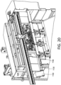
- the bun separator assembly 1100 is moved laterally by means of a suitable linear actuator, not shown, along a horizontally or transversely oriented rail system 1148 in a suspended manner. As the bun separator assembly 1100 is moved from right to left, as viewed within FIGURE 20 , the various bun segments from the housing sections 1102,1104,1106 of the bun separator assembly 1100 will be disposed above a chute 1150.
- the angle iron 1130 terminates at the chute 1150 whereby, as the bun separator assembly 1100 continues to move from the right to the left, as viewed within FIGURE 20 , the successive housing sections 1102,1104,1106 of the bun separator assembly 1100 will successively move beyond the leftwardmost extent of the angle iron 1130 and therefore, the bun segments, disposed within the housing sections 1102,1104, 1106 of the bun separator assembly 1100, will simply drop onto the chute 1150.
- the bun handling system 100 of the present invention also comprises three bun rotators 1152,1154,1156 which are mounted upon a first linear railing and actuating system 1158 for lateral or transverse movement in the leftward and rightward directions as viewed, for example, within FIGURE 22 .
- the three bun rotators 1152,1154,1156 are also mounted upon a second linear railing and actuating system 1160 which is, itself, mounted upon the first linear railing and actuating system 1158 so as to permit the three bun rotators 1152,1154,1156 to be moved in a perpendicular direction with respect to its lateral or transverse direction of movement along the first linear railing and actuating system 1158.
- a pair of toaster appliances 1162,1164 are disclosed within FIGURE 23 , and at least one of the toaster appliances 1162 can also be seen within FIGURE 21 , and accordingly, it can now be appreciated that the mounting of the three bun rotators 1152,1154,1156 upon the first linear railing and actuating system 1158 not only permits the three bun rotators 1152,1154, 1156 to move toward the rightmost position, as viewed within FIGURE 22 such that the three bun rotators 1152,1154,1156 are successively disposed beneath the chute 1150 in order to individually and respectively receive the three bun segments from the chute 1150, but in addition, the three bun rotators 1152,1154,1156 can then be moved along the first linear railing and actuating system 1158 so as to individually and successively deposit the bun segments into proper bun segment reception slots, not shown, defined within either one of the toaster appliances 1162,1164.
- the provision of the second linear railing and actuating system 1160 permits the three bun rotators 1152,1154,1156 to be moved in the noted perpendicular direction, with respect to its movement along the first linear railing and actuating system 1158, so as to enable the three bun rotators 1152,1154,1156 to be effectively moved in XY directions so as to be capable of transferring the bun segments from the three bun rotators 1152,1154,1156 into either one of the toaster appliances 1162,1164 which correspond to the toaster appliance 200 illustrated within FIGURE 1 along the automatic food preparation line 10.
- each one of the three bun rotators 1152,1154,1156 effectively defines a mounting plate system comprising a first, fixed, foam-backed mounting plate 1166, and a second movable mounting plate 1168 to which is respectively attached a pneumatic piston-cylinder assembly 1170,1172,1174, all three of which are disclosed within FIGURE 19 but only one of which is disclosed within FIGURE 21 .
- first and second mounting plates 1166,1168 are provided with non-stick sheets 1176,1178 such that when the second movable mounting plate 1168 is actuated so as to move toward the first fixed mounting plate 1166 and thereby secure the bun segment therebetween, the bun segment will not stick or adhere to either one of the mounting plates 1166,1168.
- the three bun rotators 1152,1154,1156 are collectively connected to a rotary actuator mechanism 1180 such that the three bun rotators 1152,1154,1156 can be collectively rotated 180° in opposite directions.
- the three bun rotators 1152,1154,1156 are all fixedly connected to a common transversely oriented mounting bar or rail1159.
- This mounting and actuation system permits the three bun rotators 1152,1154,1156 to collectively rotate relative to the toaster appliances 1162,1164 so as to ensure, for example, that when the three segments of the bun 108 are inserted into the proper locations defined within the toaster appliances 1162,1164, the heel and crown segments of the bun will be toasted only upon one side thereof, that is, the interior surface portions of the heel and crown segments, while with respect to the club segment of the bun, both sides of the club segment of the bun 108 will be toasted.
- the bun segments will be conveyed downwardly through the toaster appliances so as to be toasted to a predetermined degree as the segments travel continuously along their toaster paths.
- Various bun segment sensors may be incorporated internally within the toaster appliances so as to ensure that the bun segments are in fact being properly conveyed in their downward directions through the toaster appliances 1162,1164.
- the toasted bun segments fall onto a bun ramp 1182 which has been illustrated within FIGURE 23 for clarity purposes, but normally, such bun ramp 1182 would not be visible because a bun gate 1184 actually covers the bun ramp 1182.
- the bun gate 1184 is operatively connected to a pair of bun gate rotators 1186,1186 disposed at opposite ends of the bun gate 1184, and a plurality of bun ramp sensors, not shown, are operatively associated with the bun ramp 1182 so as to ensure that all bun segments that have travelled through the toaster appliances 1162,1164, and that have been toasted, have in fact reached the bump ramp 1182.
- the bun ramp sensors when the bun ramp sensors, not shown, sense the disposition of the bun segments upon the bun ramp 1182, the bun ramp sensors will transmit a signal to the bun ramp rotators 1186,1186 so as to rotate the bun gate 1184 from its normally CLOSED position to an OPEN position whereby the bun segments will fall down onto transversely oriented linear bun conveyors 1188 which are part of the conveyor system 700 illustrated within FIGURE 1 and which run along the entire length of the automatic food preparation line 10.
- the bun conveyors 1188 are activated until a bun segment reaches the end of its bun conveyor 1188 as determined by means of an upstanding bun stop 1190 which has been illustrated both within FIGURE 23 .
- a first embodiment of a bun segment gripper assembly 1192 mounted upon an overhead linear actuator and railing assembly 1194 for vertical movement toward and away from the bun conveyor 1188 by means of a suitable actuator 1189, is moved into position above the bun segment which has been stopped at the bun stop 1190, and as guided to the precise position above the stopped bun segment by means of a bun stop sensor 1195 generating a laser beam 1196.
- the bun segment gripper assembly 1192 is then lowered such that a plurality of fingers 1198 can be moved radially inwardly with respect to each other so as to grasp the bun segment, remove it from the bun conveyor 1188, and move it downstream to the next food item preparation station such as, for example, a packaging dispensing station for dispensing pre-selected box or wrapping paper packaging for housing or containing the bun segment,
- an alternative bun segment pickup system 1200 for picking up the bun segments disposed against the upstanding bun stop 1190.
- the bun segment pickup system 1200 comprises an upper mounting plate 1202 which is adapted to be operatively connected upon the lower end of a suitable actuator, not shown but similar to the actuator 1189 illustrated within the system disclosed and described in connection with FIGURE 24 . Accordingly, the bun segment pickup system 1200 can be moved vertically so as to be lowered or raised relative to the bun segment disposed upon the end of bun conveyor 1188 and disposed at its predetermined location along the bun conveyor 1188 by means of the upstanding bun stop 1190.
- a bun segment discharge plate 1204 is fixedly mounted to the lower distal end of a piston 1206 which is disposed within a cylinder 1208 of a pneumatic piston-cylinder assembly 1210 which is fixedly secured within a lower mounting plate 1212 which, together with a pair of columns 1214,1214 and the upper mounting plate 1202, effectively form the framework for the bun segment pickup system 1200.
- a plurality of vertically oriented, dependent needles 1216 which are fixedly mounted within the lower mounting plate 1212, project downwardly and pass through the bun segment discharge plate 1204 such that the bun segment discharge plate 1204 is movable relative to the plurality of needles 1216.
- the bun segment discharge plate 1204 is disposed at an elevated position, as defined by the upward movement of the piston 1206 within the cylinder 1208 of the piston cylinder assembly 1210, and subsequently, the entire bun segment pickup system 1200 is lowered by means of its pneumatic actuator, not shown, to which the upper mounting plate 1202 is connected.
- the bun segments when the bun segments, particular the heel and crown segments of the bun, which are to be toasted only upon their interior surface portions, are inserted into the toaster appliances 1162,1164, the bun segments will be properly oriented so as to in fact ensure that they are only toasted upon their interior surface portions.
- the bun segments when the bun segments are discharged onto the bun ramp 1182, the bun segments will in fact be properly oriented such that the interior toasted surface portions of the bun segments face upwardly.
- the plurality of dependent needles 1216 will penetrate the toasted internal side of the heel or crown segments of the bun, or either toasted side of the club segment of the bun, so as to effectively grasp the bun segment as a result of the penetration of the bun segment by means of the plurality of dependent needles 1216, the penetrated surface of the bun segment being disposed in contact with the undersurface portion of the bun segment discharge plate.
- the bun segment pickup system 1200 is then moved downstream toward the food packaging or wrapping paper packaging station at which time the piston 1206 will be extended or lowered with respect to the cylinder 1208 which will, in turn, cause the bun segment discharge plate 1204 to move downwardly, relative to the plurality of needles 1216, whereby the bun segment discharge plate 1204 will effectively push the bun segment off the distal end portions of the plurality of needles 1216 such that the bun segment can now be disposed within the proper box or wrapping paper packaging.
- the new and improved automatic box packaging dispensing system of the present invention is disclosed and is generally indicated by the reference character 300 as is also seen in FIGURE 1 .
- a new and improved automatic wrapping paper packaging dispensing system of the present invention is also disclosed and is generally indicated by the reference character 400 as is also seen in FIGURE 1 .
- the new and improved automatic box packaging dispensing system of the present invention 300 will be described first. More particularly, it is seen that the new and improved automatic box packaging system 300 is adapted to dispense packaging boxes and therefore comprises a packaging box sub-system 302.
- the packaging box sub-system 302 comprises a plurality of different types or sizes of packaging boxes that are disposed within different packaging box assemblies 306 which are fixedly mounted at their upper end portions upon a mounting plate 308 which is operatively connected to a linear belt drive 310 by means of a mounting bracket 312 disposed atop a linear slide block 314 which is connected to the linear belt drive 310.
- a reversible motor 316 is operatively connected to the linear belt drive 310 so that when the reversible motor 316 is actuated in a first mode for a predetermined amount of time, the linear belt drive 310 will move the mounting plate 308 and the plurality of packaging box assemblies 306 mounted thereon a predetermined distance in a first direction, whereas, when the reversible motor 316 is actuated in a second mode for a predetermined amount of time, the linear belt drive 310 will move the mounting plate 308 and the plurality of packaging box assemblies 306 mounted thereon a predetermined distance in a second opposite direction.
- the mounting plate 308 undergoes its lateral, reciprocating movements as a result of being movably attached to, and supported upon, a horizontally oriented guide rail 318 as can be seen in FIGURES 27 and 28 .
- any one of the plurality of packaging box assemblies 306 can be moved so as to be properly positioned relative to, and beneath, a vacuum suction cup pickup and transfer assembly 320, which can be seen in FIGURE 27 and which will be more fully discussed hereinafter, such that the vacuum suction cup pickup and transfer assembly 320 can remove the uppermost packaging box, one exemplary box 322 being disclosed within FIGURE 32 , disposed within the particular packaging box assembly 306 and thereby transfer the packaging box 322 onto the food preparation line conveyor 700, as seen in FIGURE 1 , such that the particular packaging box may be moved to the next food preparation station of the food preparation line 100, which will be the sauce dispensing station 500 as seen in FIGURE 1 .
- each packaging box assembly 306 comprises a box support platform 328 upon which a plurality of a particular kind or type of packaging boxes 322 are to be stacked so as to effectively form a packaging box magazine from which the uppermost packaging box 322 will be removed by means of the vacuum suction cup assembly 320.
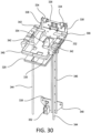
- the box support platform 328 actually comprises a horizontally oriented component 330, upon which the stack of packaging boxes 322 are actually disposed and supported, and an upstanding bracket 332 to which a pair of laterally spaced constant force springs 334 are adapted to be attached, although the springs 334 are not shown attached in FIGURE 30 .
- the springs 334 are mounted upon a horizontal spindle 336, the ends of which are mounted within laterally spaced end brackets 338.
- the end brackets 338,338, in turn, are connected to a peripheral framework 340 which is mounted upon the mounting plate 308 and to which are attached a plurality, for example, four, leaf-spring type fingers 342, as well as a pair of vertically oriented packaging box guide rods 344 which depend vertically downwardly from opposite sides of the peripheral framework 340.
- the peripheral framework 340 and the vertical guide rods 344 are adapted to maintain the stack of packaging boxes 322 upon the stacking platform component 330, with the vertical guide rods 344 engaging corner regions 346 of the packaging boxes 322, as seen in FIGURE 32 , which are effectively defined between the upper or cover portion of the packaging box 322 and the bottom portion of the packaging box 322.
- the disposition of the vertical guide rods 344 within the corner regions 346 of the packaging boxes 322 effectively prevents the plurality of packaging boxes 322 from moving forwardly and backwardly as well as laterally from side to side.
- the upper end portions 341 of the vertical guide rods 344 are bent at an angle of 90° and are seated within slots 343 defined within the peripheral framework 340. Accordingly, the upper end portions 341 of the pair of vertical guide rods 344 may be moved within the slots 343 and relative to each other such that the distance between the pair of vertical guide rods 344 is rendered adjustable. In this manner, different packaging boxes 322, having different width dimensions, can be housed or accommodated within the packaging box assembly 306.
- mounting plates 345 are fixedly secured atop the peripheral framework 340 so as to securely fix the bent end portions 341 of the vertical rods 344 within the slots 343 of the peripheral framework 340 so that, in turn, the pair of vertical rods 344 will remain at their relative desired spacing so as to house or accommodate the differently sized packaging boxes 322.
- the box support platform 328 will be moved downwardly and the constant force springs 334, when attached to the rear upstanding wall component 332 of the box support platform 328, will be extended such that the constant force springs 334 will continuously tend to move the box support platform 328 back toward its uppermost position so as to continuously move the box support platform 328 incrementally upwardly as the uppermost packaging box 322 is removed from the box support platform 328 by means of the vacuum suction cup assembly 320.
- the box support platform 328 moves vertically downwardly and upwardly along a vertically oriented guide rail 346 which is fixedly secured at its lower end to a mounting bracket 348.
- the plurality of fingers 342 extending into the central part of the peripheral framework 340 supply a sufficient retaining force to the stack of packaging boxes 322 disposed upon the horizontal component 330 of the packaging box platform 328, however, when the uppermost packaging box 322 is removed by means of the vacuum suction cup assembly 320, the plurality of fingers 342 will flex upwardly, permitting the uppermost packaging box 322 to be withdrawn from the stack of packaging boxes 322 disposed upon the horizontal component 330 of the packaging box platform 328, and will effectively slide along the external surface portions of the uppermost packaging box 322 being withdrawn by means of the vacuum suction cup assembly 320 until the fingers 342 snap back to their original positions, thereby preventing any further packaging boxes 322 from being removed from the packaging box assembly 306.
- the packaging box assembly 306 also includes a packaging box sensor 352 which is adapted to be coaxially aligned with an aperture 354 defined within the horizontal component 330 of the packaging box platform 328.
- the sensor 352 will sense when the last packaging box 322 has been removed from the packaging box assembly 306 whereby the supply of packaging boxes 322 needs to be replenished.
- a pair of suction cups 354 are fixedly attached to the bottom surfaces of a pair of vacuum manifolds 356 so that the system comprises four suction cups 354.
- Each one of the vacuum manifolds 356 is fluidically connected to a vacuum generator 358, and the vacuum generators 358,358 are fixedly mounted upon a horizontally oriented mounting bracket 360.
- a plurality of vertically oriented tubes or guide rods 362 have their lower ends fixedly connected to the mounting bracket 360 and are operatively associated with a servo unit 364 which is fixedly mounted upon a vertically extending housing 366.
- the vertically oriented housing 366 is fixedly mounted upon a mounting plate 370 and that the mounting plate 370 is fixedly connected to a servo unit 372 which, in turn, is slidably movable upon a linear slide 374. Accordingly, when the servo unit 372 moves along the linear slide 374, it will cause the suction cup assembly, comprising the mounting plate 370, the housing 366, the tubes 362 and the servo unit 364, and the mounting bracket 360, the vacuum generators 358, the vacuum manifolds 356, and the vacuum suction cups 354 to move laterally toward the left or right as viewed within FIGURES 33 and 34 , or to move into or out of the page as viewed within FIGURE 27 .
- the servo unit 364 can effectively cause the tubes or guide rods 362 to move upwardly and downwardly so as to, in turn, cause the mounting bracket 360, the vacuum generators 358, the vacuum manifolds 356, and the vacuum suction cups 354 to move upwardly and downwardly.
- the vacuum pickup and transfer assembly 320 can be moved to a position whereby the plurality of vacuum suction cups 354 will be disposed above a selected one of the plurality of packaging box assemblies 306 which has been moved into position beneath the vacuum suction cups 354 of the vacuum pickup and transfer assembly 320 by means of the linear belt drive 310.
- the vacuum control generators 358 can then be actuated, and then the servo unit 364 can be actuated so as to move the vacuum suction cups 354 downwardly such that the vacuum suction cups 354 can remove or extract the uppermost one of the packaging boxes 322 from the selected one of the plurality of packaging box assemblies 306.
- the servo unit 364 can then be actuated so as to elevate the packaging box 322 that has been removed or extracted from the selected packaging box assembly 306, the servo unit 372 can then be actuated so as to effectively retract the vacuum pickup and suction cup assembly 320 from its forwardmost position above the selected one of the plurality of packaging box assemblies 306 to a predetermined rearwardmost position at which the vacuum suction cups 354 will now be disposed above the food preparation line conveyor 700.
- the servo unit 364 can then be actuated again so as to lower the vacuum suction cups 354 toward the food preparation line conveyor 700, and when the vacuum suction cups 354 are disposed immediately above the food preparation line conveyor 700, the vacuum generators 358 can be deactivated whereby the packaging box 322 will be released from the vacuum suction cups 354 and deposited onto the food preparation line conveyor 700.
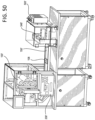
- the wrapping paper packaging sub-system 400 comprises a wrapping paper packaging housing 476 within which there is disposed a plurality of horizontally oriented, vertically spaced trays 478, each one of the trays 478 holding a predetermined number of wrapping paper packaging sheets, and wherein each tray 478 holds a different type or size of wrapping paper packaging sheet.
- An L-shaped angle iron or angle bracket 482 has its long leg fixedly secured to the rear wall 483 of the housing 476 while the short leg of the L-shaped angle iron or angle bracket 482 is fixedly secured to a slide block 480 which is part of a vertically oriented linear ballscrew actuator 484 which is driven by means of a suitable motor 486, all of which can best be seen in FIGURE 36 .
- the vertically oriented ball screw actuator 484 is also fixedly mounted upon a vertically oriented mounting platform or wall 488 which is also shown transparently within FIGURE 37 for clarity purposes.
- the rear wall 483 of the housing 476 is integrally connected to a left wall 490 of the housing 476 from which project a pair of vertically oriented, laterally spaced female track members 492 which are adapted to engage and slide along a pair of vertically oriented, laterally spaced male guide rails 494.
- the linear ballscrew actuator 484 the movement and support of the wrapping paper packaging housing 476 is provided by means of the operatively cooperative track members 492 and guide rails 494.
- a vertically oriented rail 493 is mounted upon the left wall 490 of the housing 476, while a pair of pneumatic brake components 495,495 are mounted upon the mounting platform or wall 488 so as to be disposed upon opposite sides of the vertically oriented rail 493.
- These pneumatic brake components 495,495 are provided, and are adapted to be moved toward each other so as to fixedly grasp opposite sides of the vertically oriented rail 493, so as to prevent the entire wrapping paper packaging housing 476 from falling if, for example, power to the motor 486 and the linear ballscrew actuator 484 should be terminated for some reason, such as, for example, a power switch or circuit breaker has been tripped, or the like.
- each tray 478 is also slidable upon horizontally oriented ball-bearing slides or tracks 496 which extend from the rear wall 483 of the housing 476 toward the front of the housing 476, which is open so as to permit the front edge portions of the plurality of trays 478 to project outwardly therefrom, so that the trays 478 can be easily and readily moved from their normal positions disposed internally within the tray housing 476 to external positions relative to the tray housing 476 when packaging sheets within a particular one of the trays 478 need to be accessed by means of the vacuum suction cups 354 of the vacuum pickup and transfer assembly 320.
- Each forward end of each wrapping paper tray 478 is provided with a horizontally oriented finger 498, and a horizontally oriented tray extension piston-cylinder assembly 1300 is mounted upon the external surface of the vertically oriented mounting platform or wall 488 such that when the piston of the piston-cylinder assembly 1300 is extended, the piston will encounter the finger 498 of a particular wrapping paper tray 478 and thereby cause that particular tray 478 to be moved out from the interior of the paper tray housing 476 to an external position at which the vacuum suction cups 354 of the vacuum pickup and transfer assembly 320 can engage the uppermost wrapping paper sheet within that particular wrapping paper tray 478 and then transfer that wrapping paper sheet to the food preparation line conveyor 700.
- the distal end of the piston of the piston-cylinder assembly 1300 is provided with a head portion 1302 which has a slotted section 1304, which can be seen in FIGURE 38 , through which the various fingers 498 of the various paper trays 478 can pass as the paper tray housing 476 is moved upwardly or downwardly, however, when the paper tray housing 476 has been moved upwardly or downwardly such that a particular one of the paper trays 478 is located at the correct position for that particular tray 478 to be moved out from the housing 476 such that the wrapping paper packaging sheets disposed within that tray 476 can be accessed, the finger 498 of that particular paper tray 478 will be disposed within the slotted section 1304 defined within the head portion 1302 of the piston of the piston-cylinder assembly 1300 such that when the piston-cylinder assembly 1300 is actuated, the head portion 1302 of the piston of the piston-cylinder assembly 1300 can act upon the finger 498 of that particular paper tray 478 so as to move that particular paper tray 478 outwardly from the paper
- a wrapping paper packaging sheet sensor 406 is mounted at a location upon the food preparation line 10 that is adjacent to and disposed above the wrapping paper packaging housing 476 such that when a selected paper tray 478 of the wrapping paper packaging housing 476 is extended outwardly from the wrapping paper packaging housing 476 such that the uppermost wrapping paper packaging sheet disposed within the selected paper tray 478 can in fact be grasped by means of the vacuum suction cups 354 of the vacuum pickup and transfer assembly 320 and transferred to the food preparation line conveyor 700, the wrapping paper packaging sheet sensor 406 can determine the vertical distance to the uppermost wrapping paper packaging sheet disposed within the selected paper tray 478.
- the sensor 406 will transmit a signal to the vacuum pickup and transfer assembly 320 such that, for example, the tubes and servo system 362,364 will know precisely how far to move the plurality of suction cups 354 downwardly in order to properly engage and extract the uppermost wrapping paper sheet disposed within the extended paper tray 478.
- each paper tray 478 is seen to have a substantially rectangular configuration so as to house or accommodate the various different wrapping paper packaging sheets. Accordingly, in order to permit any one paper tray 478 to house or accommodate any particularly sized wrapping paper packaging sheet, a pair of adjustable guides 1308,1310 are respectively slidably mounted within a pair of guide slots 1312,1314, all located upon two sides of each paper tray 478 which form a corner section 1316 of the paper tray 478. Set screws 1318,1320, or the like, are mounted within the adjustable guides 1308,1310 so as to fix the adjustable guides 1308,1310 at desired positions according to the particularly sized wrapping paper packaging sheets to be accommodated or housed the particular paper tray 478.
- each paper tray 478 is provided with a through-hole 1322 to permit, for example, a light beam or other sensor signal to pass therethrough so as to indicate that the supply of wrapper paper packaging sheets, disposed within the tray 478, has been depleted, such a sensing system again being similar in operation to a paper supply sensor system incorporated within a photocopying machine.
- a first new and improved automatic sauce-type condiment dispensing system is disclosed and is generally indicated by the reference character 500.
- the new and improved automatic sauce dispensing system 500 can be integrally incorporated within the automated food preparation line 10 as will be more fully discussed hereinafter. More particularly, with reference being made to FIGURES 41 and 42 , it is seen that the new and improved automatic sauce dispensing system 500 comprises a plurality of vertically oriented sauce dispensing canisters 506 respectively having sauce dispensing containers 508 removably disposed therein so as to effectively form canister or sauce container assemblies 510.
- the plurality of canister or sauce container assemblies 510 are fixedly mounted in a side-by-side manner upon a vertically oriented mounting plate 512 which is, in turn, fixedly mounted upon an automatic sauce dispensing system framework 514 as shown in FIGURE 44 .
- the canister or sauce container assemblies 510 are adapted to be mounted upon the mounting plate 512 by means of mounting blocks 516, and as can best be seen in FIGURE 43 , the mounting plate 512 is fixedly mounted upon a vertically oriented mounting bracket 518.
- the mounting bracket 518 is, in turn, mounted upon distal end portions a pair of pivotable legs or arms 520,522 which have their lower or proximal ends pivotally connected to a fixed actuator bracket 524.
- An actuator 526 which may be, for example, a pneumatic actuator, has its lower end portion pivotably mounted upon the actuator bracket 524 while its upper end portion is pivotably connected to the upper end portion of the mounting bracket 518.
- the canister/sauce dispensing container assemblies 510 will be moved between raised and lowered positions so as to be disposed at upper dispensing positions or locations or at lower positions or locations which will facilitate the exchange of depleted sauce containers 508 with new or fresh sauce containers 508 containing full supplies of the particular sauces which are to be disposed at the sauce dispensing station of the sauce dispensing system 500 and along the automatic food preparation line 10.
- each one of the canister/sauce container assemblies 510 includes an upper removable canister cap 528 which may be attached to the canister 506 by means of any suitable quick disconnect type fastener such as, for example, complementary threads, a quarter turn type fastener, a bayonet type fastener, or the like.
- a pneumatic air fitting 530 which effectively passes through the removable canister cap 528 so as to be in fluidic communication with the interior of the sauce container 508.
- the pneumatic air fitting 530 when the pneumatic air fitting 530 is fluidically connected to a source of pressurized air, not shown, the pressurized air will act upon the sauce contained within the sauce container 508 so as to pressurize the same and thereby cause the same to be dispensed out from the lower end portion of the sauce container 508 through means of a nipple or suitable connector 532 which likewise passes through the lower end portion of the canister 506.
- the sauce from the sauce container 508 will be able to pass out from the sauce container 508 and into the fluid hose or conduit, not shown, so as to be conveyed to a dispensing valve disposed within a valve bank, as will be discussed more fully hereinafter, such that the sauce can in fact be dispensed and deposited onto a food product as will also be more fully discussed and better appreciated hereinafter.
- each canister/sauce container assembly 510 is respectively employed with each canister/sauce container assembly 510 so as to provide warning signals to food preparation personnel that the volumetric amount of sauce remaining within a particular sauce container 508 has reached a predetermined level.
- the level sensors comprise, for example, a first light beam transmitter 536 which can, for example, send a light beam through the canister/sauce container assembly 510, and a light beam receiver 538 which is disposed diametrically opposite the light beam transmitter 536 so as to receive the light beam signal from the light beam transmitter 536 which passes through the canister/sauce container assembly 510.
- One or more sets of light beam transmitters 536 and receivers 538 may be utilized so as to provide food preparation personnel with different alarms or warnings as to how much sauce remains within a particular sauce container 508. For example, as shown in FIGURES 41 and 43 , two pairs of light beam transmitters 536 and light beam receivers 538 are being utilized. Therefore, for example, when the level of the sauce remaining within the sauce container 508 reaches the upper pair of level sensors 536,538, an alarm or signal will be transmitted so as to warn food preparation personnel that the particular sauce container 508 will soon need to be replaced.
- the light sensing system is attuned or calibrated in such a manner that the sensor system can determine the difference between a sufficient supply of sauce remaining within the sauce container 508 and a film of sauce which may remain upon interior peripheral wall portions of the sauce container 508 as the sauce container 508 becomes depleted.
- the number of individual canister/sauce container assemblies 510 may be, for example, seven, however a fewer or greater number of canister/sauce container assemblies may be employed depending upon the particular needs of the particular food establishment.
- two, side-by-side food product conveyors 540,542, comprising component conveyors of the overall automatic food preparation line conveyor system 700, are being utilized to convey food products along the food preparation line, although, again, depending upon the particular needs of the particular food establishment, a fewer or greater number of food product conveyors can be utilized.
- each one of the sauce containers 508 is adapted to be fluidically connected to a sauce dispensing valve assembly 544, which is more clearly illustrated within FIGURES 45 and 46 and which will be more fully discussed hereinafter, by means of a suitable flexible hose or conduit, not shown.
- the plurality of sauce dispensing valve assemblies 544 are disposed within two valve banks 546,548 wherein, for example, the first valve bank 546 may house three sauce dispensing valve assemblies 544 which are to be fluidically connected to three of the seven illustrated canister/sauce container assemblies 510, while the second valve bank 548 may house four sauce dispensing valve assemblies 544 so as to be fluidically connected to the remaining four of the seven illustrated canister/sauce container assemblies 510.
- First and second servo motor drives 550,552 are mounted upon three horizontally oriented, vertically spaced guide rods 554,556, and the valve banks 546,548 are respectively mounted in a dependent manner upon the servo motor drives 550,552 so that as the servo motor drives 550,552 are driven and moved along the guide rods 554,556, the valve banks 546,548 will move correspondingly.
- the sauce dispensing valve assemblies 544 can effectively be located at any predetermined "xy" coordinate relative to the food product conveyors 540,542, and relative to any food product located upon the food product conveyors 540,542 as a result of the movement of the food product conveyors 540,542 in the "x" direction and the movement of the valve banks 546,548 in the "y” direction.
- a predetermined amount of sauce from a particular sauce dispensing valve assembly 544 of one of the valve banks 546,548 can in fact be deposited onto a particular food product at any time and at any location, and in various manners or modes, as a result of the predeterminedly timed coordination of the movement of the food product conveyors 540,542 and the valve banks 546,548.
- the servo drive motor 550 is mounted upon the guide rods 554 such that the first valve bank 546 is disposed above the first food product conveyor 540 so as to be moved in the "y" direction across the first food product conveyor 540, while in a similar manner, the servo drive motor 552 is mounted upon the guide rods 556 such that the second valve bank 548 is disposed above the second food product conveyor 540 so as to be moved in the "y" direction across the second food product conveyor 542. It is also to be noted that the entire operation of the automatic sauce dispensing system 500, and the various operative components thereof, are under the control of the programmable logic controller (PLC) 800.
- PLC programmable logic controller
- the sauce dispensing valve assemblies 544 comprise pinch valves type assemblies. More particularly, the valve assembly 544 comprises a housing 560 within which a key-hole shaped slot 562 is provided for permitting the particular sauce hose or conduit, not shown, to be passed therethrough whereby the distal end portion of the hose or conduit will be disposed within an adjustable C-clamp or C-clip 564.
- a thumb screw 566 is operatively associated with the C-clamp or C-clip 564 such that as the thumb screw 566 is rotated in one direction, the diametrical extent of the C-clamp or C-clip 564 is contracted, thereby tightly engaging the distal end portion of the sauce hose or conduit, while when the thumb screw 566 is rotated in the opposite direction, the diametrical extent of the C-clamp or C-clip 564 is expanded so as to accommodate different sized sauce hoses or conduits.
- a horizontally oriented bar 568 is disposed within the housing 560 at a position adjacent to where the sauce hose or conduit passes through the key-hole shaped slot 562 such that the lower distal end thereof is disposed within the C-clamp or C-clip 564.
- a pneumatic actuator is disposed internally within an actuator housing 570, and it is seen that the actuator housing 570 is provided with a pair of pneumatic air inlet/outlet fittings 572,574 disposed at opposite ends of the actuator housing 570.
- the actuator disposed internally within the actuator housing 570, will be forced to move toward the right as viewed within FIGURES 45 and 46 , thereby causing a plunger or actuator head 576, fixedly mounted upon the distal end of the actuator, to be moved toward the right and into contact with the transversely oriented bar 568 so as to thereby pinch the sauce hose or conduit to a closed position, thereby terminating any dispensing of the sauce from the sauce hose or conduit.
- the actuator is moved within the actuator housing 570, air disposed in front of the actuator disposed within the actuator housing 510 will of course be expelled through means of the outlet fitting 574.
- the actuator head 576 when air is admitted into the air inlet fitting 574, the actuator head 576 will be retracted toward the left so as to effectively relieve the pinching of the sauce hose or conduit, thereby permitting sauce to be dispensed from the sauce dispensing valve assembly 544. While the actuator is being moved toward the left, air behind the actuator will of course be permitted to be expelled or exhausted through means of air outlet fitting 572. It is lastly noted that a coil spring 578 is disposed around the shaft of the actuator so as to normally bias the actuator, and the actuator head 576, toward the right so as to normally maintain the sauce dispensing valve assembly 544 at its closed position. This is to prevent undesirable leakage or dispensing of the sauce in the event that the control air of the pneumatic control system experiences a failure.
- the automatic sauce dispensing system also includes a self-cleaning system which cleans the canisters, the conduits or hoses, and the valves disposed within the valve banks such that food preparation personnel do not have to be involved in the cleaning of the system which is automatically rendered clean at specified intervals such that the sauces being dispensed are always fresh and do not become contaminated.
- first and second drip trays 580,582 are disposed along the sides of the food product conveyors 540,542 and are adapted to be linearly aligned with the first and second valve banks 546,548 when the first and second valve banks 546,548 are disposed at their end-of-travel positions along their respective guide rods 554,556.
- the first and second valve banks 546,548 will be respectively disposed above the first and second drip trays 580,582 such that if any residual leakage, dripping, or dropping of sauce from any one of the plurality of dispensing valve assemblies 544 mounted upon either one of the first and second valve banks 546,548 occurs, such leakage, dripping, or dropping of such sauce will be caught by means of the first and second drip trays 580,582.
- first and second drip trays 580,582 are adapted to be removably mounted atop first and second cleaning funnels or drains 584,586.
- the automatic sauce dispensing system 500 of the present invention automatic food preparation line 10 includes an automatic cleaning system wherein the first and second funnels or drains 584,586 are component parts of such automatic cleaning system.
- the first and second drip trays 580,582 are removed from the first and second cleaning funnels or drains 584,586, the pneumatic air lines are disconnected from the pneumatic air fittings 530 provided at the upper end of each canister/sauce container assembly 510, and cleaning solution tubes, hoses, conduits, or the like, not shown, are fluidically connected to such fittings 530.
- a cleaning solution supply CSS is generally indicated at 588 so as to contain a supply of cleaning solution which may comprise, for example, a suitable cleaning solution, a degreaser or sanitizer, and heated water with enhances the degreasing or sanitizing agents within the solution, and a pump P, generally indicated by the reference character 590, is interposed fluidically between the cleaning solution supply 588 so as to pump the cleaning solution into the canister or sauce container assemblies 510 through means of the fittings 530.
- a pump P generally indicated by the reference character 590
- the cleaning solution will then flow through the cleaning solution hoses or conduits, not shown, through the sauce containers 508, and through the conduits or hoses, also not shown, fluidically connecting the canister/sauce container assemblies 510 to the valve banks 546,548, and through the valve mechanisms 544 of the valve banks 546,548 such that the cleaning solution can then exit the valve banks 546,548 and be discarded into the cleaning funnels or drains 584,586.
- the new and improved automatic condiment dispensing system 600 comprises a hopper mechanism 602 within the bottom portion of which a progressive auger-type conveyor 604 is rotatably disposed.
- a condiment charging bin 606 is removably disposed atop the hopper mechanism 602 so as to contain a charge of condiment therein which may be discharged into the hopper mechanism 602 when a horizontally oriented panel, valve, or gate mechanism 608 is opened.
- the condiment charging bin 606 has a vertically downward, elongated, outwardly tapered configuration such that the largest diametrical portion of the charging bin 606 is disposed adjacent to the hopper mechanism 602. In this manner, condiments can be freely deposited into the hopper mechanism 602 and fully engaged with the auger-type conveyor 604 without encountering any vertical movement impediments.
- the uppermost portion of the condiment charging bin 606 has a cover or lid 610 removably attached thereto so as to permit a fresh charge of condiment to be charged into the charging bin 606 and thereafter maintain the condiment, disposed within the charging bin 606, in a relatively fresh state as a result of the charging bin 606 not being open to the ambient atmosphere.
- the left or upstream end portion of the auger-type conveyor 604 is adapted to be mounted within a rotary bearing 612 provided upon the hopper mechanism 602 so as to be capable of being rotated around its longitudinal axis L by means of a suitable drive motor 614, as a result of which the auger-type conveyor 604 will move condiments, disposed within the condiment hopper mechanism 602, from the left or upstream end 616 of the hopper mechanism 602 to an oppositely disposed downstream or discharge end 618 of the hopper mechanism 602.
- a vertically oriented condiment chamber 620 is integrally connected to, or defined within, the discharge end 618 of the hopper mechanism 602 wherein it is appreciated that the vertically oriented condiment chamber 620 defined within the discharge end 618 of the hopper mechanism 602 effectively forms a tubular end portion which is open at its lower or bottom end portion and is adapted to hold or retain a predetermined amount or quantity of the particular condiment as a result of a horizontally oriented, movable valve or weighing gate 622 effectively closing off the open bottom end portion of the condiment chamber 620 of the hopper mechanism 602 when the horizontally oriented, movable valve or weighing gate 622 is disposed at its leftwardmost position as illustrated within FIGURES 47 and 48 .
- the horizontal diametrical extent of the valve or weighing gate 622 effectively bridges diametrically opposite wall portions of the discharge end 618 of the hopper mechanism 602 which define the condiment chamber 620.
- suitable condiments may be shredded lettuce, shredded onions, shredded cheese, and the like, although other food items can be envisioned such as, for example, cold cereals, tortilla chips, and the like.
- the drive motor 614 may be a suitable, electric drive motor and is operatively connected to the auger-type conveyor 604 by means of a rotary bearing connector 624.
- a load cell 626 is electronically connected to the valve or weighing gate 622 so as to accurately determine the amount or quantity or weight of the condiment disposed within the condiment chamber 620 and disposed atop the valve or weighing gate 622, the load cell 626 being fixedly mounted beneath the electric drive motor housing 628. As is well-known, the load cell 626 may of course be pre-calibrated to a predetermined load or weight.
- the load cell 626 determines that the condiment disposed within the holding chamber 620 is approaching the predetermined amount or quantity or load or weight of the condiment that is desired to be dispensed onto a food item, the load cell 626 will transmit a suitable electrical signal to a central controller or programmable logic controller (PLC) 800, as is illustrated within FIGURE 47 , whereby the programmable logic controller (PLC) 800 will, in turn, send a signal to the drive motor 614 so as to gradually reduce the rotational speed at which the drive motor 614 is rotating the auger conveyor 604.
- PLC programmable logic controller
- the activation of the drive motor 614 will be terminated as will the rotation of the auger-type conveyor 604 such that no additional condiment is moved into the condiment holding chamber 620 and onto the valve or weighing gate 622.
- valve or weighing gate 622 effectively comprises a plate wherein a distal end portion 630 of the plate 622 is disposed beneath the discharge end 618 of the condiment holding chamber 620, when the valve or weighing gate 622 is disposed at its leftwardmost position, as illustrated within FIGURES 47 and 48 , so as to effectively close off the discharge end 618 of the condiment holding chamber 120, however, the proximal end portion 632 of the plate 622 is fixedly secured to a horizontally oriented leg portion 634 of an L-shaped bracket 636 which is adapted to be moved in a reciprocal manner within a horizontal plane as a result of a vertically oriented leg portion 638 of the L-shaped bracket 636 being fixedly connected to a piston rod 640 of a dual-movement or dual-actuated pneumatic piston-cylinder assembly 642 as can best be seen in FIGURE 47 .
- the pneumatic piston-cylinder assembly 642 is fixedly mounted beneath the load cell housing 644 as can best be seen in FIGURE 48 , and is also electronically connected to the programmable logic controller (PLC) 800.
- PLC programmable logic controller
- the plate 622 also has an intermediate bent portion 646 next to which there is disposed a vertically oriented scraper 648 which is fixedly mounted to an L-shaped mounting bracket 650 which serves to mount the pneumatic piston-cylinder assembly housing 652 to the bottom wall of the load cell housing 644, and wherein it is also seen that the horizontally oriented leg portion 634 of the L-shaped bracket 636 is movable within a slot 654 of the piston-cylinder assembly housing 652.
- the scraper 648 may be fabricated from any suitable metal, such as, for example, stainless steel or aluminum, and is adapted to engage the intermediate bent portion 646 of the valve or weighing gate or plate 622.
- the scraper 648 is fixedly mounted upon a flexible mounting plate 656 which may be fabricated from, for example, a suitable rubber, neoprene, TEFLON R or polytetrafluoroethylene (PTFE), or the like.
- a flexible mounting plate 656 which may be fabricated from, for example, a suitable rubber, neoprene, TEFLON R or polytetrafluoroethylene (PTFE), or the like.
- the scraper 648 as mounted upon the flexible mounting plate 656, is adapted to be pivoted toward the right, when the valve/weighing gate/plate 622 is caused to be moved toward the right by means of the piston rod 640 of the pneumatic piston-cylinder assembly 642 when the pneumatic piston-cylinder assembly 642 causes the entire valve/weighing gate/plate 622 to be moved toward the right when the open discharge end 618 of the hopper mechanism 602 is to be uncovered so as to permit the dispensing or deposition of the condiment from the condiment holding chamber 620 onto a food item.
- This movement of the piston rod 640 of the piston-cylinder assembly 642 is also under the control of the programmable logic controller (PLC) 800, and it is also to be particularly noted that due to the inherent resiliency of the flexible mounting plate 656, the scraper 648 will always be maintained in contact with the upper surface portion 658 of the valve or weighing gate 622, throughout the entire retraction stroke of the piston 640 of the piston-cylinder assembly 642, so as to ensure that all of the condiment initially disposed upon the upper surface portion 658 of the valve or weighing gate 622 will in fact be scraped off the upper surface portion 658 of the valve or weighing gate 622, forced into the condiment holding chamber 620, and will be permitted to be deposited onto the food item disposed at the condiment dispensing station.
- PLC programmable logic controller
- an all-encompassing condiment dispensing system of the present invention can include a plurality of condiment dispensing systems 600 under the control of a central programmable logic controller (PLC) 800 which is not only adapted to be electronically connected to individual condiment dispensing systems 600 which may be located at predetermined condiment dispensing stations located at predetermined locations along a food preparation line so as to control the various operations of the various different mechanisms at a particular one of the condiment dispensing stations, such as, for example, the operation of the auger conveyor 604, the processing of signals from the load cell 626 so as to, in turn, control the valve or weighing gate 622 as a result of activating the rotary drive motor 120 and the piston-cylinder assembly 642, but in addition, the central programmable logic controller (PLC) 800 is also adapted to be electronically connected to the plurality of condiment dispensing systems 600 which may be located at a multitude of condiment dispensing stations located at a multitude of predetermined locations along the automatic food preparation line 10 so that
- the central programmable logic controller (PLC) 800 controls each condiment condiment dispensing system 600 located at each condiment dispensing station, but in addition, the central programmable logic controller (PLC) 800 controls the conveyance of a food item to a particular food preparation station or between the multitude of food preparation stations along the automatic food preparation line 10 such that food items are properly prepared in accordance with a patron's food order.
- This arrangement of multiple stations can of course be implemented for other operations as may be desired or required.
- the food preparation line 10 would therefore include, for example, multiple food preparation stations in order to complete the hamburger preparation operation, such as, for example, the hamburger bun handling station 100, the bun toaster station 200, the box packaging station 300, the wrapping paper packaging station 400, the sauce dispensing station 500, and one or more condiment dispensing stations 600.
- multiple food preparation stations in order to complete the hamburger preparation operation, such as, for example, the hamburger bun handling station 100, the bun toaster station 200, the box packaging station 300, the wrapping paper packaging station 400, the sauce dispensing station 500, and one or more condiment dispensing stations 600.
- a particular food patron has ordered his or her hamburger with shredded lettuce and shredded cheese but no shredded onions.
- the central programmable logic controller (PLC) 800 advances the conveyor system 700 carrying the hamburger bun to the first condiment dispensing station 500 which comprises a plurality of different sauces to be applied to the hamburger bun.
- the first condiment dispensing station 500 comprises a plurality of different sauces to be applied to the hamburger bun.
- this particular patron has elected not to have any sauces dispensed onto the hamburger bun.
- the conveyor system 700 conveys the hamburger bun to a first one of a plurality of condiment dispensing stations 600 which may be, for example, a shredded lettuce condiment dispensing station.
- a predetermined amount of shredded lettuce will be deposited onto the hamburger bun.
- the programmable logic computer (PLC) 800 will advance the conveyor system of the food preparation line 10 to the second condiment dispensing station 600, however, the second condiment dispensing station 600 may be, for example, a shredded cheese condiment dispensing station, but in accordance with the patron's food order, the patron does not want shredded cheese on his or her hamburger bun.
- PLC programmable logic computer
- the programmable logic controller (PLC) 800 will effectively know to bypass this second condiment dispensing station 600 and will move the conveyor system 700 further along the food preparation line 10 such that the hamburger bun is now located at a third condiment dispensing station 600 which is a shredded onion dispensing station.
- PLC programmable logic controller
- a particular condiment dispensing station may effectively comprise a condiment dispensing station wherein such condiment dispensing station will dispense a combination of condiments.
- data may be derived from hundreds or thousands of patron orders that patrons often desire shredded cheese and shredded lettuce to be deposited onto their hamburgers. Therefore, a particular condiment dispensing station will have its hopper mechanism charged with a mixture of shredded cheese and shredded lettuce. In this manner, not only does the patron obtain his or her desired hamburger with the specified condiments, but the operational speed is enhanced since the food preparation conveyor need only be halted at a single condiment dispensing station in lieu of multiple condiment dispensing stations.
- condiment charging bins having different configurations or sizes, are possible.
- thermal devices may be employed in connection with the condiment charging bins so as to maintain the condiments relatively hot or relatively cold, depending upon the particular condiment.
- each canister/sauce container assembly has been fluidically connected to a single dispensing valve assembly through means of its dedicated fluid hose or conduit, more than one fluid hose or conduit maybe connected to a particular dispensing valve assembly so that the volumetric output of that particular dispensing valve assembly may be increased as may be desired.
- each canister or sauce container assembly will contain a particular sauce or condiment such as, for example, mustard, ketchup, or the like, two hoses or conduits, carrying different sauces, may likewise effectively be fluidically connected together at a particular dispensing valve assembly such that a combination of sauces is simultaneously dispensed onto a particular bun.
- the sauce containers can be pre-heated or pre-cooled. In this manner, for example, if cheese is to be deposited onto nacho food products, patrons may prefer that the cheese be warmed or heated to above ambient or room temperature.
- the cabinets comprise various doors which can be opened whereupon food preparation personnel can extract an exhausted or depleted bun storage tube and can be manually refilled or replaced by means of a new or fresh bun storage tube such that the plurality of bun storage tubes are always properly stocked in order to permit the system to be operated in a continuous manner without any operational downtime.
- the various surfaces of the system components such as, for example, the interior surface portions of the bun storage tubes, and/or the internal surface portions of the housing sections of the bun separator assembly, can be provided with non-stick surface coatings so as to prevent any of the bun segments from sticking or adhering to such surfaces.
- FIGURES 50-52 still further modifications or embodiments are possible in accordance with the present invention as long as they fall under the scope of the appended claims.
- a particular food establishment may have to contend with predetermined spatial constraints, or, for example, financial constraints, whereby, for one reason or another, the entire automatic food preparation line 10 as illustrated within FIGURE 1 , cannot be erected and utilized within the particular establishment.
- abbreviated, shortened, or partial automatic food preparation lines can nevertheless be erected and utilized within a particular food establishment as a result of making each one of the primary components of the automatic food preparation line 10, that is, the bun handling system 100, the toaster appliance 200, the box packaging system 300, the wrapping paper packaging system 400, the sauce dispensing system 500, the condiment dispensing system 600, and the conveyor system 700, as modular components which can be used solely or in conjunction with other modular components.
- FIGURE 50 there is shown a modular or compact automatic bun handling system 100' being utilized in conjunction with a modular or compact automatic toaster appliance 200', a modular or compact automatic conveyor system 700', and a modular or compact automatic sauce dispensing system 500', which includes the valve banks 548', which will receive the buns 108 conveyed thereto by means of the automatic conveyor system 700'.
- a manually operated toaster appliance may be utilized with a modular or compact automatic sauce dispensing system 500'.
- a modular or compact automatic bun handling system 100' may be utilized with a modular or compact automatic toaster appliance 200'.
Landscapes
- Engineering & Computer Science (AREA)
- Food Science & Technology (AREA)
- Life Sciences & Earth Sciences (AREA)
- Physics & Mathematics (AREA)
- General Physics & Mathematics (AREA)
- Mechanical Engineering (AREA)
- Chemical & Material Sciences (AREA)
- Polymers & Plastics (AREA)
- Container Filling Or Packaging Operations (AREA)
- Table Equipment (AREA)
- Manufacturing And Processing Devices For Dough (AREA)
Claims (12)
- Ligne de préparation culinaire automatique (10) pour préparer des produits de pain (108) pour hamburgers et sandwiches, comprenant :une interface utilisateur (900) pour entrer diverses sélections différentes par un client en ce qui concerne la manière dont un produit de pain (108) pour un élément culinaire doit être préparé ;un système de manipulation automatique (100) de produit de pain, présentant une pluralité de types différents de produits de pain (108), pour distribuer automatiquement des produits de pain (108) particuliers conformément aux sélections entrées par le client à l'aide de ladite interface utilisateur (900) ;un système de distribution automatique (500, 600) de condiment, comprenant une pluralité de condiments différents, pour distribuer automatiquement un ou plusieurs condiments sur le produit de pain (108) conformément aux sélections entrées par le client à l'aide de ladite interface utilisateur (900) ;un système de transporteur automatique (700) pour transporter les produits de pain (108) depuis ledit système de manipulation automatique (100) de produit de pain jusqu'audit système de distribution automatique (500, 600) de condiment, et depuis ledit système de distribution automatique de condiment jusqu'à un poste de préparation culinaire en aval au niveau duquel un élément culinaire est disposé sur le produit de pain (108) ; etun système de commande informatique pour commander toutes les opérations automatiques dudit système de manipulation automatique (100) de produit de pain, dudit système de distribution automatique (500, 600) de condiment et dudit système de transporteur automatique (700),caractérisée en ce que ledit système de manipulation automatique (100) de produit de pain comprend :
une pluralité de tubes de stockage (104) de produit de pain pour stocker une pluralité de produits de pain (108) différents à sélectionner par le client en entrant des informations sélectives dans ladite interface utilisateur (900), dans laquelle :
ladite pluralité de tubes de stockage (104) de produit de pain sont disposés sur un carrousel transporteur sans fin orienté à la verticale de telle sorte que le tube particulier de ladite pluralité de tubes de stockage de produit de pain est déplacé jusqu'à un emplacement de sortie (106) de produit de pain prédéterminé défini sur ledit carrousel transporteur sans fin. - Ligne de préparation culinaire automatique (10) selon la revendication 1, dans laquelle :
ledit système de manipulation automatique (100) de produit de pain comprend un séparateur (1100) de produit de pain comprenant un boîtier présentant au moins deux sections (1102, 1104, 1106) de boîtier pour recevoir respectivement des segments fond et couronne d'un produit de pain de type bun. - Ligne de préparation culinaire automatique (10) selon la revendication 1, dans laquelle :
ledit système de manipulation automatique de produit de pain comprend un boîtier de séparateur de produit de pain comprenant trois sections de boîtier (1102, 1104, 1106) pour recevoir respectivement des segments fond, club intermédiaire et couronne d'un produit de pain de type bun. - Ligne de préparation culinaire automatique (10) selon la revendication 1, comprenant en outre :
un appareil de grille-pain automatique (200) fonctionnellement relié audit système de manipulation automatique (100) de produit de pain pour griller automatiquement des produits de pain (108) distribués automatiquement par ledit système de manipulation automatique (100) de produit de pain et pour sortir automatiquement les produits de pain (108) grillés dudit appareil de grille-pain automatique (200) lorsque les produits de pain ont été correctement grillés. - Ligne de préparation culinaire automatique (10) selon la revendication 1, comprenant en outre :
un système de distribution automatique (300, 400) d'emballage pour distribuer automatiquement un emballage particulier dans lequel les produits de pain distribués par ledit système de manipulation (100) de produit de pain peuvent être disposés. - Ligne de préparation culinaire automatique (10) selon la revendication 5, dans laquelle :
ledit système de distribution automatique (300, 400) d'emballage comprend un système d'emballage (300) par boîte comprenant une pluralité de piles d'emballages en boîte orientées à la verticale à distribuer en fonction du type d'emballage nécessité par l'élément culinaire particulier sélectionné par le client entrant les sélections du client dans ladite interface utilisateur (900). - Ligne de préparation culinaire automatique (10) selon la revendication 6, comprenant en outre :
un ensemble ventouse sous vide (320) pour extraire un emballage en boîte (322) le plus haut de l'une de ladite pluralité de piles d'emballages en boîte orientées à la verticale. - Ligne de préparation culinaire automatique (10) selon la revendication 5, dans laquelle :
ledit système de distribution automatique (300, 400) d'emballage comprend un système d'emballage (400) par papier d'enveloppement comprenant un groupement vertical de bacs (478) dans lesquels divers types différents d'emballage par papier d'enveloppement sont stockés de manière à être distribués en fonction du type d'emballage nécessité par l'élément culinaire particulier sélectionné par le client entrant les sélections du client dans ladite interface utilisateur (900). - Ligne de préparation culinaire automatique (10) selon la revendication 8, comprenant en outre :
un ensemble ventouse sous vide (354) pour extraire une feuille d'emballage par papier d'enveloppement la plus haute d'une pile d'emballage par papier d'enveloppement de l'un de ladite pluralité de bacs (478) d'emballage par papier d'enveloppement orientés à la verticale. - Ligne de préparation culinaire automatique (10) selon la revendication 1, comprenant en outre :
un système de distribution automatique (500, 600) de condiment pour distribuer automatiquement au moins un type de condiment sur un produit de pain (108) conformément à une sélection entrée par le client à l'aide de ladite interface utilisateur (900). - Ligne de préparation culinaire automatique (10) selon la revendication 10, dans laquelle :
ledit système de distribution automatique (500, 600) de condiment comprend un premier système de distribution automatique (500) de condiment pour distribuer au moins une d'une pluralité de sauces différentes sur le produit de pain (108) conformément aux sélections entrées par le client à l'aide de ladite interface utilisateur (900) et comprend une pluralité de récipients (510) de sauces différentes destinés à contenir ladite pluralité de sauces différentes, une pluralité de vannes de distribution (544) de sauce destinées à distribuer une ou plusieurs de ladite pluralité de sauces différentes depuis ladite pluralité de récipients (510) de sauces différentes sur un bun, et une pluralité de conduits de fluide reliant fluidiquement ladite pluralité de récipients (510) de sauce à ladite pluralité de vannes de distribution (544) de sauce. - Ligne de préparation culinaire automatique (10) selon la revendication 11, dans laquelle :
ladite pluralité de vannes de distribution (544) de sauce sont montées sur des bancs (546, 548) de vannes de distribution de sauce qui sont mobiles dans des directions XY par rapport audit système de transporteur automatique (700) de manière à positionner précisément une vanne particulière de ladite pluralité de vannes de distribution (544) de sauce au-dessus d'un produit de pain disposé sur ledit système de transporteur automatique (700).
Applications Claiming Priority (2)
| Application Number | Priority Date | Filing Date | Title |
|---|---|---|---|
| US201962845349P | 2019-05-09 | 2019-05-09 | |
| PCT/US2020/032404 WO2020227723A1 (fr) | 2019-05-09 | 2020-05-11 | Ligne de préparation culinaire automatique |
Publications (3)
| Publication Number | Publication Date |
|---|---|
| EP3965581A1 EP3965581A1 (fr) | 2022-03-16 |
| EP3965581A4 EP3965581A4 (fr) | 2023-01-11 |
| EP3965581B1 true EP3965581B1 (fr) | 2024-05-01 |
Family
ID=73047482
Family Applications (1)
| Application Number | Title | Priority Date | Filing Date |
|---|---|---|---|
| EP20801905.9A Active EP3965581B1 (fr) | 2019-05-09 | 2020-05-11 | Ligne de préparation culinaire automatique |
Country Status (5)
| Country | Link |
|---|---|
| US (1) | US11798343B2 (fr) |
| EP (1) | EP3965581B1 (fr) |
| JP (1) | JP2022531901A (fr) |
| CN (1) | CN114144065A (fr) |
| WO (1) | WO2020227723A1 (fr) |
Family Cites Families (17)
| Publication number | Priority date | Publication date | Assignee | Title |
|---|---|---|---|---|
| US3859904A (en) * | 1971-12-20 | 1975-01-14 | Jose B Carriazo | Automated variable selection sandwich preparation device |
| US4797291A (en) * | 1985-07-01 | 1989-01-10 | William W. Pierce | Method of preparing a comestible with insert |
| US5113753A (en) * | 1987-06-23 | 1992-05-19 | Design Technology Corporation | Apparatus for automatic application of condiments to a sandwich |
| FR2629701B1 (fr) * | 1988-04-12 | 1991-01-25 | Cresson Christian | Machine pour la confection et la distribution d'hamburgers |
| IT1265570B1 (it) * | 1993-07-27 | 1996-11-22 | Ivan Tocchet | Distributore automatico alimentare particolarmente per cibi caldi quali toast - panini - pizzette - briosches |
| JP3321632B2 (ja) * | 1994-04-14 | 2002-09-03 | 株式会社共和工業所 | ハンバーガー調理システム |
| US8276505B2 (en) * | 2004-02-18 | 2012-10-02 | David Benjamin Buehler | Food preparation system |
| US8069953B2 (en) * | 2008-03-25 | 2011-12-06 | Restaurant Technology, Inc. | Food item cooking, assembly and packaging system and method |
| US20120185086A1 (en) * | 2011-01-18 | 2012-07-19 | K & G Enterprises, Llc | automated pizza preparation apparatus |
| US9295282B2 (en) * | 2012-06-06 | 2016-03-29 | Momentum Machines Company | System and method for dispensing toppings |
| US9532575B1 (en) * | 2013-03-06 | 2017-01-03 | Victor Donisi | Automated sandwich assembly unit |
| US9950437B2 (en) * | 2014-04-25 | 2018-04-24 | Anas Al Afandi | Methods and apparatuses for preparing Shawarma, Gyros and Doner kebab sandwiches and meals |
| CN113475729A (zh) * | 2016-04-04 | 2021-10-08 | 创造者公司 | 将调味料和酱汁分配到食品上的系统和方法 |
| WO2018085796A1 (fr) * | 2016-11-04 | 2018-05-11 | Adam Cohen | Procédés et appareil pour la préparation automatisée d'aliments |
| JP7158575B2 (ja) * | 2018-06-20 | 2022-10-21 | クリエーター インコーポレイティッド | トッピングを分配するシステム及び方法 |
| WO2020006257A1 (fr) * | 2018-06-27 | 2020-01-02 | Prince Castle LLC | Systèmes et procédés de maintien et de grillage de petits pains |
| US11357254B2 (en) * | 2019-11-01 | 2022-06-14 | Kevin J. Saccone, Jr. | Sub roll slicing and conveying apparatus |
-
2020
- 2020-05-11 US US16/872,291 patent/US11798343B2/en active Active
- 2020-05-11 EP EP20801905.9A patent/EP3965581B1/fr active Active
- 2020-05-11 WO PCT/US2020/032404 patent/WO2020227723A1/fr unknown
- 2020-05-11 JP JP2021566184A patent/JP2022531901A/ja active Pending
- 2020-05-11 CN CN202080049231.5A patent/CN114144065A/zh active Pending
Also Published As
| Publication number | Publication date |
|---|---|
| CN114144065A (zh) | 2022-03-04 |
| US11798343B2 (en) | 2023-10-24 |
| EP3965581A4 (fr) | 2023-01-11 |
| US20200357220A1 (en) | 2020-11-12 |
| EP3965581A1 (fr) | 2022-03-16 |
| WO2020227723A1 (fr) | 2020-11-12 |
| JP2022531901A (ja) | 2022-07-12 |
Similar Documents
| Publication | Publication Date | Title |
|---|---|---|
| US20210100396A1 (en) | Methods and Apparatus for Automated Food Preparation | |
| US20210009289A1 (en) | Bagging System for Packaging a Foodstuff | |
| US11089905B2 (en) | Automated bun handling system | |
| US4646627A (en) | Apparatus for preparing fried potato products | |
| JP3786709B2 (ja) | ピザを製造するための装置および方法 | |
| KR102061439B1 (ko) | 성분들을 보존 및 계측하기 위한 시스템 및 이러한 시스템을 구현하는 보존 및 계측 방법 | |
| US20060263192A1 (en) | Method and apparatus for stacking discrete planar objects | |
| US10948336B2 (en) | Automated condiment dispensing system with precisely controlled dispensed quantities | |
| WO2019090352A1 (fr) | Procédés et appareil pour la préparation automatisée d'aliments | |
| EP3965581B1 (fr) | Ligne de préparation culinaire automatique | |
| US10988324B2 (en) | Food grade feeder device and system for rolls, sandwiches, odd shaped edibles and foodstuff | |
| US20190320846A1 (en) | Horizontal griddle with automatic dispensing | |
| CA1330739C (fr) | Appareil et methode pour la preparation de produits a base de pommes de terre frites | |
| US20120216490A1 (en) | Methods and apparatus for handling stackable articles | |
| CN113226129B (zh) | 用于根据顾客订单处理不同类型和数量的面点的自动面点处理系统 | |
| NL2009290C2 (en) | Food vending system. | |
| WO2023199329A1 (fr) | Système et procédé de préparation autonome d'aliments | |
| US20240132299A1 (en) | Ultimate Cleanable Food grade feeder device and system for rolls, sandwiches, odd-shaped edibles and foodstuff | |
| US20210030048A1 (en) | Food grade feeder device and system for placing rolls, egg, meat, or protein patties, and/or cheese and other foodstuffs to assemble and prepare a sandwich | |
| CN114144371A (zh) | 自动包装分配系统 | |
| WO2021257840A1 (fr) | Système et procédé de manipulation et de grillage automatisés de petits pains |
Legal Events
| Date | Code | Title | Description |
|---|---|---|---|
| STAA | Information on the status of an ep patent application or granted ep patent |
Free format text: STATUS: THE INTERNATIONAL PUBLICATION HAS BEEN MADE |
|
| PUAI | Public reference made under article 153(3) epc to a published international application that has entered the european phase |
Free format text: ORIGINAL CODE: 0009012 |
|
| STAA | Information on the status of an ep patent application or granted ep patent |
Free format text: STATUS: REQUEST FOR EXAMINATION WAS MADE |
|
| 17P | Request for examination filed |
Effective date: 20211208 |
|
| AK | Designated contracting states |
Kind code of ref document: A1 Designated state(s): AL AT BE BG CH CY CZ DE DK EE ES FI FR GB GR HR HU IE IS IT LI LT LU LV MC MK MT NL NO PL PT RO RS SE SI SK SM TR |
|
| DAV | Request for validation of the european patent (deleted) | ||
| DAX | Request for extension of the european patent (deleted) | ||
| A4 | Supplementary search report drawn up and despatched |
Effective date: 20221209 |
|
| RIC1 | Information provided on ipc code assigned before grant |
Ipc: A47J 44/00 20060101ALI20221205BHEP Ipc: A47J 43/00 20060101ALI20221205BHEP Ipc: A47J 27/14 20060101ALI20221205BHEP Ipc: A21D 15/00 20060101ALI20221205BHEP Ipc: A21C 9/00 20060101ALI20221205BHEP Ipc: A21C 15/00 20060101AFI20221205BHEP |
|
| GRAP | Despatch of communication of intention to grant a patent |
Free format text: ORIGINAL CODE: EPIDOSNIGR1 |
|
| STAA | Information on the status of an ep patent application or granted ep patent |
Free format text: STATUS: GRANT OF PATENT IS INTENDED |
|
| RIC1 | Information provided on ipc code assigned before grant |
Ipc: G07F 17/00 20060101ALI20231103BHEP Ipc: G07F 13/06 20060101ALI20231103BHEP Ipc: G07F 11/58 20060101ALI20231103BHEP Ipc: B65B 43/18 20060101ALI20231103BHEP Ipc: B65B 25/00 20060101ALI20231103BHEP Ipc: A23P 20/20 20160101ALI20231103BHEP Ipc: A21C 15/00 20060101AFI20231103BHEP |
|
| INTG | Intention to grant announced |
Effective date: 20231127 |
|
| GRAS | Grant fee paid |
Free format text: ORIGINAL CODE: EPIDOSNIGR3 |
|
| GRAA | (expected) grant |
Free format text: ORIGINAL CODE: 0009210 |
|
| STAA | Information on the status of an ep patent application or granted ep patent |
Free format text: STATUS: THE PATENT HAS BEEN GRANTED |
|
| AK | Designated contracting states |
Kind code of ref document: B1 Designated state(s): AL AT BE BG CH CY CZ DE DK EE ES FI FR GB GR HR HU IE IS IT LI LT LU LV MC MK MT NL NO PL PT RO RS SE SI SK SM TR |
|
| REG | Reference to a national code |
Ref country code: GB Ref legal event code: FG4D |
|
| REG | Reference to a national code |
Ref country code: CH Ref legal event code: EP |
|
| REG | Reference to a national code |
Ref country code: IE Ref legal event code: FG4D |
|
| REG | Reference to a national code |
Ref country code: DE Ref legal event code: R096 Ref document number: 602020030289 Country of ref document: DE |