EP3965000A1 - Étiquette rfid, lecteur et méthode d'encodage d'une étiquette rfid - Google Patents
Étiquette rfid, lecteur et méthode d'encodage d'une étiquette rfid Download PDFInfo
- Publication number
- EP3965000A1 EP3965000A1 EP21195556.2A EP21195556A EP3965000A1 EP 3965000 A1 EP3965000 A1 EP 3965000A1 EP 21195556 A EP21195556 A EP 21195556A EP 3965000 A1 EP3965000 A1 EP 3965000A1
- Authority
- EP
- European Patent Office
- Prior art keywords
- rfid tag
- tag
- reader
- resonator
- resonator elements
- Prior art date
- Legal status (The legal status is an assumption and is not a legal conclusion. Google has not performed a legal analysis and makes no representation as to the accuracy of the status listed.)
- Pending
Links
- 238000000034 method Methods 0.000 title claims abstract description 20
- 239000000758 substrate Substances 0.000 claims abstract description 16
- 230000033001 locomotion Effects 0.000 claims abstract description 13
- 238000009826 distribution Methods 0.000 claims description 23
- 230000005540 biological transmission Effects 0.000 claims description 19
- 239000011159 matrix material Substances 0.000 claims description 18
- 238000001514 detection method Methods 0.000 claims description 13
- 230000008878 coupling Effects 0.000 claims description 10
- 238000010168 coupling process Methods 0.000 claims description 10
- 238000005859 coupling reaction Methods 0.000 claims description 10
- 230000004044 response Effects 0.000 claims description 8
- 230000005672 electromagnetic field Effects 0.000 claims description 6
- 230000001902 propagating effect Effects 0.000 claims description 5
- 239000003989 dielectric material Substances 0.000 claims description 4
- 230000005284 excitation Effects 0.000 description 4
- 238000005516 engineering process Methods 0.000 description 3
- XUIMIQQOPSSXEZ-UHFFFAOYSA-N Silicon Chemical compound [Si] XUIMIQQOPSSXEZ-UHFFFAOYSA-N 0.000 description 2
- 239000004020 conductor Substances 0.000 description 2
- 239000000463 material Substances 0.000 description 2
- 230000009467 reduction Effects 0.000 description 2
- 229910052710 silicon Inorganic materials 0.000 description 2
- 239000010703 silicon Substances 0.000 description 2
- 230000000694 effects Effects 0.000 description 1
- 238000004519 manufacturing process Methods 0.000 description 1
- 239000003550 marker Substances 0.000 description 1
- 229920003023 plastic Polymers 0.000 description 1
- 239000004033 plastic Substances 0.000 description 1
- 230000008569 process Effects 0.000 description 1
- 230000001681 protective effect Effects 0.000 description 1
- 230000006798 recombination Effects 0.000 description 1
- 238000005215 recombination Methods 0.000 description 1
- 239000000126 substance Substances 0.000 description 1
- 230000001131 transforming effect Effects 0.000 description 1
Images


Classifications
-
- G—PHYSICS
- G06—COMPUTING; CALCULATING OR COUNTING
- G06K—GRAPHICAL DATA READING; PRESENTATION OF DATA; RECORD CARRIERS; HANDLING RECORD CARRIERS
- G06K7/00—Methods or arrangements for sensing record carriers, e.g. for reading patterns
- G06K7/10—Methods or arrangements for sensing record carriers, e.g. for reading patterns by electromagnetic radiation, e.g. optical sensing; by corpuscular radiation
- G06K7/10009—Methods or arrangements for sensing record carriers, e.g. for reading patterns by electromagnetic radiation, e.g. optical sensing; by corpuscular radiation sensing by radiation using wavelengths larger than 0.1 mm, e.g. radio-waves or microwaves
- G06K7/10316—Methods or arrangements for sensing record carriers, e.g. for reading patterns by electromagnetic radiation, e.g. optical sensing; by corpuscular radiation sensing by radiation using wavelengths larger than 0.1 mm, e.g. radio-waves or microwaves using at least one antenna particularly designed for interrogating the wireless record carriers
- G06K7/10336—Methods or arrangements for sensing record carriers, e.g. for reading patterns by electromagnetic radiation, e.g. optical sensing; by corpuscular radiation sensing by radiation using wavelengths larger than 0.1 mm, e.g. radio-waves or microwaves using at least one antenna particularly designed for interrogating the wireless record carriers the antenna being of the near field type, inductive coil
-
- G—PHYSICS
- G06—COMPUTING; CALCULATING OR COUNTING
- G06K—GRAPHICAL DATA READING; PRESENTATION OF DATA; RECORD CARRIERS; HANDLING RECORD CARRIERS
- G06K19/00—Record carriers for use with machines and with at least a part designed to carry digital markings
- G06K19/06—Record carriers for use with machines and with at least a part designed to carry digital markings characterised by the kind of the digital marking, e.g. shape, nature, code
- G06K19/067—Record carriers with conductive marks, printed circuits or semiconductor circuit elements, e.g. credit or identity cards also with resonating or responding marks without active components
- G06K19/0672—Record carriers with conductive marks, printed circuits or semiconductor circuit elements, e.g. credit or identity cards also with resonating or responding marks without active components with resonating marks
- G06K19/0677—Record carriers with conductive marks, printed circuits or semiconductor circuit elements, e.g. credit or identity cards also with resonating or responding marks without active components with resonating marks the record carrier being programmable
Definitions
- the present invention relates to the field of the radio frequency identification (RFID) systems.
- RFID radio frequency identification
- the present invention relates to an RFID system comprising a multifrequency RFID tag and a reading device allowing a quick reading of the tag with high density in coded information.
- the identification systems through radio frequency have acquired in the last years increasing importance in the production field, for example in the field of logistics or tracing of supply chains, by evolving towards increasingly advanced applications.
- RFID Radio Frequency Identification
- RFID radio frequency identification
- the first ones mainly have limitations linked to high cost and, in some applications, they can be conveniently replaced by the second ones which, as to constructive features, overcome such limitation but, on the other hand, they have drawbacks linked to the reduced amount of information which can be stored in the tag itself.
- the chipless RFID technology guarantees a relevant cost reduction since the tags are typically based on moulded encoders which replace the integrated circuits made of silicon. Such tags can be implemented both in flexible (for example LCP, paper, etc.) and stiff substrates.
- the moulded encoder can be wholly integrated with the tagging element with the purpose of providing unique identification signatures, interesting for the authentication and safety applications (banknotes, certificates, official and business documents, exams, cards, etc.).
- each one of the publications EP3104307A1 , WO2009/126999A1 and CN208705916U discloses a tag integrating coding resonators and antennas for receiving/transmitting an electromagnetic signal, wherein the tag comprises resonators in fixed position and distance with respect to a central microstrip transmission line and wherein the signal is read remotely for all resonators of the tag.
- the publication WO2018220109A1 discloses a tag wherein identical electromagnetic resonators which use one single resonance frequency are associated to coding areas and they are spatially-equidistant arranged.
- the technical problem placed and solved by the present invention then is to provide an RFID tag allowing to obviate one or more of the drawbacks mentioned above with reference to the know art.
- Such problem is solved by an RFID tag according to claim 1.
- the invention further relates to a reader and to a method of encoding an RFID tag as defined in claim 8 and 16, respectively.
- Preferred features of the present invention are set forth in the depending claims.
- the present invention then relates to an RFID tag, a reader and a coding method which overcomes the above-mentioned limitations, in particular, a reduced reading speed and a limited amount of codable information.
- the tag of the invention comprises a dielectric substrate and a plurality of resonator elements excitable by an external electromagnetic field.
- the resonator elements are carried by the dielectric substrate according to a distribution of predefined spatial positions.
- At least a first resonator element of said plurality is configured to resonate at a first resonance frequency distinct from a second resonance frequency of a second resonator element, wherein the first and second resonance frequency are selected among a plurality of predefined resonance frequencies.
- the above-said dielectric substrate is divided into predetermined coding areas so that data, associable to the tag, are coded according to said distribution of spatial positions and of the resonance frequency of each resonator element with respect to each one of said predetermined coding areas.
- the use of resonator elements configured to resonate at different resonance frequencies allows to increase the possible number of logical states which can be associated to the single coding area.
- Such feature has the effect of increasing the coding density of the tag, by allowing a significant reduction in its sizes and a considerable increase in the amount of information contained thereby.
- the distribution of the resonator elements according to predefined spatial positions on the dielectric substrate allows to further increase the amount of codable information.
- the tag of the invention is deprived of means for propagating electromagnetic waves.
- Such propagating means, of which the tag of the invention is deprived thereof, is meant to identify antennas or transmission lines, for example microstrip transmission lines, indeed configured for propagating (or transmitting) electromagnetic waves.
- the invention provides a reader of RFID tag and a relative coding method wherein the codified data are preferably detected through a simultaneous reading of said electromagnetic resonators.
- the reader is near-field coupled with the RFID tag.
- the reader comprises an active reading element, functional to the coding method, in particular a microstrip transmission line.
- the tag comprises in substance exclusively resonator elements and that the reading can take place in near field and not remotely, as it would happen if the tag bore propagating means of electromagnetic waves, such as antennas or transmission lines.
- the reader carries an active reading element, in particular the microstrip transmission line, configured to propagate the excitation electromagnetic signal and to transmit a response signal received by each resonator element.
- the resonator elements are constrained to be in very proximate position to the microstrip, constrain which prevents them to be arranged freely on the tag.
- all resonator elements operate at different frequencies, since their reading takes place for all simultaneously.
- the resonator elements can be distributed according to rows or columns or other arbitrary geometries, and their frequencies can repeat, since the reading takes place in a not simultaneous way for all the resonator elements carried by the tag, but through a scanning of the predetermined coding areas on the tag.
- These differences allow to expand indefinitely the number of codable bits, by simply increasing the number of resonators present in the tag. In other words, the maximum number of bits only depends upon the number and spatial arrangement of the resonator elements and, consequently, upon the physical sizes of the tag, and then it can be expanded at will.
- FIG. 1 a scheme exemplifying a system 1 is illustrated comprising a preferred embodiment of an RFID tag, designated with reference 100 and a reader of said RFID tag, designated with reference 10.
- the configuration of the RFID tag of the present invention is based on the chipless technology which, as known to the person skilled in the art, is a configuration deprived of the integrated circuits made of silicon typically necessary to implement the radio frequency identification functionalities.
- the RFID tag of the present invention is an RFID tag of chipless type.
- Such system 1 has its preferred intended use in the field of the supply chain, of logistics and in the applications related to the identification and tracking of goods.
- the RFID tag 100 comprises a dielectric substrate 11 acting as support for a plurality of electromagnetic resonator elements 2.
- the dielectric substrate 11 preferably is a substrate made of flexible material, for example plastics or paper.
- the tag 100 can then be applied, incorporated or carved in a stiff body, such as for example a box-like body which preferably has a planar surface.
- Each resonator element 2 can be excited by an electromagnetic field external to the tag 100 and comprises electrically conductive material according to defined pattern or motifs.
- the resonator elements 2 preferably comprise a planar structure and they are carried by said dielectric substrate 11 according to a distribution of defined spatial positions Ps.
- any type of planar resonator which can be excited by an external electromagnetic field can be used, for example with spiral, split ring, geometry in form of dipoles, or any other planar electromagnetic resonator which can be excited by an external electromagnetic field.
- the electromagnetic resonator elements 2 are distributed, or arranged, at defined spatial positions Ps of the dielectric substrate 11, for example according to n rows and/or m columns so as to form a matrix of positions Ps, regular or with the staggered columns/rows.
- the resonator elements 2 can be arranged according to other convenient geometrical distributions.
- the distribution of the resonator elements is so that at least a first resonator element 2a is configured to resonate at a first resonance frequency F Ra distinct from a second resonance frequency F Rb of a second resonator element 2b.
- the first and second resonance frequency are comprised among a plurality of predefined resonance frequencies F R .
- the resonator elements 2 are not configured to resonate all at the same resonance frequency, but each one resonates at a frequency F R selected among the plurality of predefined resonance frequencies.
- Each resonance frequency F R is comprised in a range of predefined values, preferably said range is comprised between 0.5 GHz and 20 GHz.
- the plurality of predefined resonance frequencies F R comprises a number of frequencies comprised between 2 and 50. The overall number of resonance frequencies F R can be even higher.
- the distribution of frequencies F R within said range of values of resonance frequencies can correspond to a linear, logarithmic distribution or other non-linear distribution.
- a possible coding configuration of the tag 100 is represented, wherein a division of the dielectric substrate 11 in predetermined coding areas 110 can be seen.
- Said data can be information related, for example, to the content of the article carrying the tag 100.
- the number, presence or absence in determined spatial positions Ps and the resonance frequency F R of each one of the resonator elements 2 determines in a unique way the coding of data contained in the tag 100, according to a coding method which will be described subsequently.
- the above-said spatial positions Ps can constitute, for example, the above-mentioned matrix of n rows and/or m columns.
- each predetermined coding area 110 comprises a resonator element 2 and one single spatial position Ps, such as for example for the configuration illustrated in Figure 5 .
- a predetermined coding area 110 can include two or more of said spatial positions Ps.
- each coding area 110 comprises four spatial positions Ps.
- the invention provides a coding system 1 which is based upon the presence or absence, on the spatial position Ps and on the value of the resonance frequency F R of each resonator element 2.
- the expression "absence" of electromagnetic resonator element 2 relates to one of the following alternative cases: the absence of an electromagnetic resonator 2 or the presence of an electromagnetic resonator 2 which resonates outside its own pre-established resonance frequency F R when excited by an external electromagnetic field.
- the presence or the absence of each one of the predefined frequencies can correspond to one bit of coded information.
- a logical state "0" can be associated to a coding area 110 when it is characterized by the absence of electromagnetic resonator 2.
- the distribution of the resonator elements 2 is in accordance to a matrix of three rows and six columns, in each coding area a resonator element 2 is present or absent and the data associated to the tag 100 coded in binary code are shown.
- the binary code consists of three rows and six columns in a way corresponding to the number of predetermined coding areas 110 associated to the tag 100.
- resonator element 2 which resonates at its own resonance frequency corresponds to the logical state "1".
- the tag 100 it is possible to alter the structure of one or more resonator elements 2c so as to modify the respective resonance frequency F R .
- the logical state "0" then can be even obtained by adding or removing conductive material from a specific resonator element 2, in this way by moving its resonance frequency F R outside the interest range. With such method it is possible to modify the reading of the predetermined coding area 110, by transforming a logical state "1" into a logical state "0” or vice versa.
- the reader 10 of the tag 100 comprises a dielectric support 101 movable relative to the tag 100 and means 15 for generating an excitation electromagnetic signal, configured to excite the above-mentioned resonator elements 2.
- the relative movement between the reader 10 and the tag 100 can be controlled manually or, for example through automatic systems.
- the reader 10 is a functional device to the coding method of the tag 100 and comprises detection means 16 of a response signal 160 from the resonator elements 2.
- the reader 10 is configured to detect a response signal 160 which preferably comprises attenuation peaks of electromagnetic waves associated to the resonance frequencies F R of the resonator elements 2.
- the coding system of the present invention is a system allowing to process the data detected by the reader 10 producing coded data, for example a binary or alphanumeric code. It will be appreciated that the fact of providing a plurality of predefined frequencies F R reduces considerably the number of resonator elements 2 required to obtain a defined number of bits, thus by increasing the information density contained in the tag 100.
- the dielectric support 101 carries an active reading element which comprises a microstrip transmission line 12.
- the reading active element is configured to propagate the excitation electromagnetic signal and to transmit to the detection means 16 the response signal 160 received by each resonator element 2.
- the reading active element is operatively connected with said generating means 15 and it is preferably supplied by the latter.
- the dielectric support 101 carries a layer of dielectric material interposed between it and the tag 100 to avoid the contact with the resonator elements 2.
- Said material layer is preferably placed at said microstrip transmission line 12.
- the microstrip transmission line 12 can be linear or angled.
- the layer of dielectric material is carried by the tag 100 to cover the resonator elements 2 (presence of dielectric material).
- the reader 10 and the tag 100 are preferably configured for a near-field electromagnetic coupling, without contact or without direct contact between the microstrip transmission line 12 and the resonator elements 2.
- the electromagnetic coupling between reader 10 and the resonator elements 2 of the tag 100 is established under proximity conditions, preferably at distance not greater than ten millimetres.
- such coupling is established with reference to the detection (or absence of detection) of attenuation peaks corresponding to the presence (or absence) of respective resonator elements 2 which resonate at their own resonance frequency F R .
- the reading active element is configured to propagate the excitation electromagnetic signal in the range of interest frequencies, preferably comprised between 0.5 GHz and 20GHz.
- the reader 10 can include guiding means to favour a correct positioning between the tag 100 and the reader 10 during their relative motion.
- the guiding means is configured to confine in a preferential direction S the relative motion between said dielectric support 101 and the tag 100.
- said relative motion can include a motion of the tag 100 with respect to the microstrip transmission line 12 in fixed position or, vice versa, the motion of the microstrip transmission line 12 with respect to the tag 100 in fixed position.
- the guiding means can include a mechanical structure, for example a rail, combined to the dielectric support 101 allowing to guide the tag 100 in case it moves.
- a mechanical structure for example a rail
- Such structure is to be meant as a confinement structure capable of allowing the motion of the tag 100 only in the wished direction, by avoiding unwished side motions.
- said structure can act as position marker, by allowing to position the tag 100 in a selected location and by making that the reading of the tag 100 starts when it is in a known reference position.
- the coding method of the tag 100 can then provide resonator elements 2 which resonate at different resonance frequencies F R for each n row / m column and/or the presence of several spatial positions Ps within the same predetermined coding area 110.
- the detection of the resonance frequencies F R of the resonator elements 2 takes place by means of reading by n rows only. In other cases, the reading takes place by n rows and m columns.
- the detection comprises a relative motion between the tag 100 and the microstrip transmission line 12 of the reader 10 along a preferential detection direction S which is parallel or orthogonal with respect to the distribution direction of spatial positions Ps of the resonator elements 2.
- simultaneous readings of two or more predetermined coding areas 110 are possible, in particular of more resonator elements 2 related to the same n row or m column.
- the electromagnetic resonator elements 2 in the same n row have each one a different resonance frequency F R and they are in number equal to the number of the predefined resonance frequencies.
- the resonator elements 2 in the same n row are read contemporarily by the reading active element by near-field electromagnetic coupling while this moves in direction S perpendicular to the n rows.
- n x N the total number of coded bits is n x N.
- a code of 96 bits, required for the standard EPC (Electronic Product Code) can be obtained with 8 rows and 12 predefined frequencies or with 6 rows and 16 predefined frequencies.
- a second coding configuration of the tag 100 is shown in Figure 4 .
- the resonator elements 2 are arranged on one or more n rows. Each row includes a number r of resonators 2 which are associated to a number N of predefined frequencies F R (including zero).
- the resonator elements resonate, each one, at a different resonance frequency F R if in the same n row, whereas they can have the same resonance frequency F R in different rows (if present).
- the r resonator elements 2 in the same row are read contemporarily by the reading active element by near-field electromagnetic coupling while this moves in direction S perpendicular to the n rows.
- the resonator elements 2 on different rows are read separately.
- n row there can be N! / [(N- r )! r !] combinations.
- the number of bits by n rows of r resonators then is equal to a n x log 2 ⁇ N! / [(N-r)! r !] ⁇ .
- F R and r 5 number of resonators by row, 4368 combinations by row are obtained equal to 12.1 bits.
- n 8 rows are sufficient to obtain 96.7 bit.
- the resonator elements 2 are arranged in a matrix with n rows and m columns. All resonator elements 2 in a same n row of the matrix at distinct frequencies F R and all resonator elements 2 in a same m column of the matrix resonate at distinct frequencies.
- the number N of minimum predefined resonance frequencies F R is then equal to the maximum between n and m . Even the possibility of absence of a resonator element 2 can be provided.
- the matrix is read by the reading active element through a contemporary reading of all resonator elements 2 along the preferential direction S, in particular on a same n row, in the same way described for the configuration of Figure 4 .
- the tag 100 After having rotated the tag 100 (or the microstrip transmission line 12) by 90° degrees, the tag 100 is read again, in particular by reading contemporarily all resonator elements 2 on a same m column.
- the tag 100 can be "replicated" through a recombination of the distribution of spatial positions Ps of the resonator elements 2, for example by providing a transposed matrix of n T rows and m T columns which includes the same resonator elements 2 provided by the original distribution.
- the reading can be implemented in only one preferential direction S.
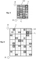
- FIG 6 shows still a different variant of the coding configuration of the tag 100 illustrated in Figure 5 .
- each predetermined coding area 110 of the matrix n x m comprises four spatial positions Ps and only one resonator element 2 which can be positioned in any one of said four spatial positions Ps within the respective predetermined coding area 110.
- Each resonator element 2 in a same n row of the matrix resonates at a different resonance frequency F R .
- each resonator element 2 in a same m column resonates at a different resonance frequency F R .
- each coding area 110 is increased from N to PsxN (with N number of predefined resonance frequencies F R ).
- the reading is implemented by n rows and by m columns with the same modes of the example of Figure 5 , but in this case the reading is further implemented for all spatial positions Ps of each coding area 110.
- N resonance frequencies F R read along the n rows and along the m columns, it is possible to reconstruct the spatial arrangement of the resonator elements 2.
- N 11 different resonance frequencies F R , and by providing four spatial positions for each coding area 110, a matrix 4x5 can code 97 bits.
- the coding method of the tag 100 provides a spatial distribution of the resonator elements 2 according to a matrix of n rows with m staggered columns. The reading is performed so that resonator elements 2 with same resonance frequency F R and arranged on different m columns are read simultaneously in a position Ps but not in the previous or in the subsequent reading. The processing of the sequence of readings in frequency whole reconstructs the arrangement of the resonator elements 2 in the tag 100.
- Resonator elements in a same column C1, C2, C3 are spaced apart therebetween by a distance d.
- Resonator elements in adjacent columns are not perfectly aligned on rows R1, R2, R3, R4, but they are moved vertically by an amount d / m wherein m is the number of columns.
- Some resonator elements in this configuration can resonate at the same (or different) resonance frequencies F R among the predefined ones or even be absent in specific predetermined coding areas 110.
- the resonator elements are preferably read whereas the microstrip transmission line 12 moves along the m columns.
- the position of the microstrip 12 is strictly associated to the reading in frequency and a same resonator element (detected by the position R1C1) is read more than once in a different relative spatial position of the microstrip 12. At least m readings equal to the number of columns have to be performed whereas the relative motion between the active reading element and the tag 100 covers a distance d.
- the number of bits for an arrangement of m columns with z resonator elements by column is equal to ( z x m )xlog 2 (N+1), where N is the number of predefined resonance frequencies F R and the absence of a resonator 2 is equivalent to an additional resonance frequency F R .
- N 15 predefined resonance frequencies F R
- 3 m columns of 8 resonators are sufficient to obtain 96 bits.
Landscapes
- Engineering & Computer Science (AREA)
- Physics & Mathematics (AREA)
- General Physics & Mathematics (AREA)
- Theoretical Computer Science (AREA)
- Health & Medical Sciences (AREA)
- Toxicology (AREA)
- Computer Networks & Wireless Communication (AREA)
- Electromagnetism (AREA)
- General Health & Medical Sciences (AREA)
- Artificial Intelligence (AREA)
- Computer Vision & Pattern Recognition (AREA)
- Radar Systems Or Details Thereof (AREA)
Applications Claiming Priority (1)
| Application Number | Priority Date | Filing Date | Title |
|---|---|---|---|
| IT202000021214 | 2020-09-08 |
Publications (1)
| Publication Number | Publication Date |
|---|---|
| EP3965000A1 true EP3965000A1 (fr) | 2022-03-09 |
Family
ID=73498149
Family Applications (1)
| Application Number | Title | Priority Date | Filing Date |
|---|---|---|---|
| EP21195556.2A Pending EP3965000A1 (fr) | 2020-09-08 | 2021-09-08 | Étiquette rfid, lecteur et méthode d'encodage d'une étiquette rfid |
Country Status (1)
| Country | Link |
|---|---|
| EP (1) | EP3965000A1 (fr) |
Citations (4)
| Publication number | Priority date | Publication date | Assignee | Title |
|---|---|---|---|---|
| WO2009126999A1 (fr) | 2008-04-16 | 2009-10-22 | Monash University | Transpondeur à radiofréquences |
| EP3104307A1 (fr) | 2015-06-08 | 2016-12-14 | Xerox Corporation | Architecture de système d'impression pour codage sans puce des étiquettes rfid en temps réel |
| WO2018220109A1 (fr) | 2017-06-01 | 2018-12-06 | Universitat Autonoma De Barcelona | Étiquette rfid sans puce, système rfid sans puce et procédé de codage de données sur une étiquette rfid sans puce |
| CN208705916U (zh) | 2018-01-26 | 2019-04-05 | 同济大学 | 一种扩充信息容量的无芯片rfid电子标签 |
-
2021
- 2021-09-08 EP EP21195556.2A patent/EP3965000A1/fr active Pending
Patent Citations (4)
| Publication number | Priority date | Publication date | Assignee | Title |
|---|---|---|---|---|
| WO2009126999A1 (fr) | 2008-04-16 | 2009-10-22 | Monash University | Transpondeur à radiofréquences |
| EP3104307A1 (fr) | 2015-06-08 | 2016-12-14 | Xerox Corporation | Architecture de système d'impression pour codage sans puce des étiquettes rfid en temps réel |
| WO2018220109A1 (fr) | 2017-06-01 | 2018-12-06 | Universitat Autonoma De Barcelona | Étiquette rfid sans puce, système rfid sans puce et procédé de codage de données sur une étiquette rfid sans puce |
| CN208705916U (zh) | 2018-01-26 | 2019-04-05 | 同济大学 | 一种扩充信息容量的无芯片rfid电子标签 |
Similar Documents
| Publication | Publication Date | Title |
|---|---|---|
| US20190138760A1 (en) | Systems, Methods and Associated RFID Antennas for Processing a Plurality of Transponders | |
| US10325194B2 (en) | Encoding module, associated encoding element, connector, printer-encoder and access control system | |
| EP1025553B1 (fr) | Antenne d'identification de frequences radioelectriques, destinee a une bande de transport | |
| Islam et al. | A novel compact printable dual-polarized chipless RFID system | |
| Preradovic et al. | Multiresonator-based chipless RFID system for low-cost item tracking | |
| US9994043B2 (en) | Near field coupling devices and associated systems and methods | |
| EP2286485B1 (fr) | Transpondeur à radiofréquences | |
| Havlicek et al. | Enhancing the per-unit-length data density in near-field chipless-RFID systems with sequential bit reading | |
| KR102639845B1 (ko) | 하이브리드 코딩을 사용하는 무칩 rfid 태그 | |
| MX2011008937A (es) | Metodo y sistema de codificacion para etiqueta rigida rfid. | |
| CN101185085A (zh) | Rfid应答器 | |
| US20180276432A1 (en) | System, method and apparatus for encoding, verifying, and printing of rfid enabled objects | |
| EP3965000A1 (fr) | Étiquette rfid, lecteur et méthode d'encodage d'une étiquette rfid | |
| Karami-Horestani et al. | Frequency-coded and programmable synchronous electromagnetic encoders based on linear strips | |
| US20080100452A1 (en) | RFID tag with barcode symbology antenna configuration | |
| CN107851880A (zh) | 分形等离子表面读取器天线 | |
| Furness | Machine‐readable data carriers–a brief introduction to automatic identification and data capture | |
| EP3631689B1 (fr) | Étiquette rfid sans puce, système rfid sans puce et procédé de codage de données sur une étiquette rfid sans puce | |
| CN113544691A (zh) | 通过阻抗变化的射频信号调制 | |
| CN112955895A (zh) | 用于对hf转发器编码的装置和方法 | |
| JP4873158B2 (ja) | Rfidリーダ装置 | |
| CN206115473U (zh) | 一种z字形变极化无芯片rfid标签及系统 | |
| JP4645545B2 (ja) | 通信システム及びタグリーダ | |
| JP6932606B2 (ja) | Rfidメディア認識方法 | |
| CN115828980A (zh) | 一种反向磁通的双天线rfid电子标签 |
Legal Events
| Date | Code | Title | Description |
|---|---|---|---|
| PUAI | Public reference made under article 153(3) epc to a published international application that has entered the european phase |
Free format text: ORIGINAL CODE: 0009012 |
|
| STAA | Information on the status of an ep patent application or granted ep patent |
Free format text: STATUS: THE APPLICATION HAS BEEN PUBLISHED |
|
| AK | Designated contracting states |
Kind code of ref document: A1 Designated state(s): AL AT BE BG CH CY CZ DE DK EE ES FI FR GB GR HR HU IE IS IT LI LT LU LV MC MK MT NL NO PL PT RO RS SE SI SK SM TR |
|
| STAA | Information on the status of an ep patent application or granted ep patent |
Free format text: STATUS: REQUEST FOR EXAMINATION WAS MADE |
|
| 17P | Request for examination filed |
Effective date: 20220909 |
|
| RBV | Designated contracting states (corrected) |
Designated state(s): AL AT BE BG CH CY CZ DE DK EE ES FI FR GB GR HR HU IE IS IT LI LT LU LV MC MK MT NL NO PL PT RO RS SE SI SK SM TR |
|
| STAA | Information on the status of an ep patent application or granted ep patent |
Free format text: STATUS: EXAMINATION IS IN PROGRESS |
|
| 17Q | First examination report despatched |
Effective date: 20231005 |