EP3964420A1 - Steuerungssystem und verfahren zur überwachung der unversehrtheit der schienen eines eisenbahngleises - Google Patents
Steuerungssystem und verfahren zur überwachung der unversehrtheit der schienen eines eisenbahngleises Download PDFInfo
- Publication number
- EP3964420A1 EP3964420A1 EP20305986.0A EP20305986A EP3964420A1 EP 3964420 A1 EP3964420 A1 EP 3964420A1 EP 20305986 A EP20305986 A EP 20305986A EP 3964420 A1 EP3964420 A1 EP 3964420A1
- Authority
- EP
- European Patent Office
- Prior art keywords
- rail
- sensor
- control
- det
- sensors
- Prior art date
- Legal status (The legal status is an assumption and is not a legal conclusion. Google has not performed a legal analysis and makes no representation as to the accuracy of the status listed.)
- Pending
Links
- 238000012544 monitoring process Methods 0.000 title claims abstract description 17
- 238000000034 method Methods 0.000 title claims abstract description 13
- 238000012545 processing Methods 0.000 claims abstract description 63
- 230000002950 deficient Effects 0.000 claims abstract description 14
- 238000012360 testing method Methods 0.000 claims description 34
- 238000003306 harvesting Methods 0.000 claims description 11
- 230000005355 Hall effect Effects 0.000 claims description 9
- 230000004907 flux Effects 0.000 claims description 3
- 230000007547 defect Effects 0.000 description 4
- 238000007689 inspection Methods 0.000 description 3
- 230000004048 modification Effects 0.000 description 3
- 238000012986 modification Methods 0.000 description 3
- 230000006399 behavior Effects 0.000 description 2
- 238000001514 detection method Methods 0.000 description 2
- 238000005516 engineering process Methods 0.000 description 2
- 230000000704 physical effect Effects 0.000 description 2
- 241000566613 Cardinalis Species 0.000 description 1
- 101000879675 Streptomyces lavendulae Subtilisin inhibitor-like protein 4 Proteins 0.000 description 1
- 230000032683 aging Effects 0.000 description 1
- 230000005540 biological transmission Effects 0.000 description 1
- 230000002860 competitive effect Effects 0.000 description 1
- 239000000428 dust Substances 0.000 description 1
- 230000007613 environmental effect Effects 0.000 description 1
- 230000003116 impacting effect Effects 0.000 description 1
- 239000000463 material Substances 0.000 description 1
- 230000000737 periodic effect Effects 0.000 description 1
- 230000003094 perturbing effect Effects 0.000 description 1
- 230000008569 process Effects 0.000 description 1
- 230000004044 response Effects 0.000 description 1
- 230000035882 stress Effects 0.000 description 1
- XLYOFNOQVPJJNP-UHFFFAOYSA-N water Substances O XLYOFNOQVPJJNP-UHFFFAOYSA-N 0.000 description 1
Images


Classifications
-
- B—PERFORMING OPERATIONS; TRANSPORTING
- B61—RAILWAYS
- B61L—GUIDING RAILWAY TRAFFIC; ENSURING THE SAFETY OF RAILWAY TRAFFIC
- B61L23/00—Control, warning or like safety means along the route or between vehicles or trains
- B61L23/04—Control, warning or like safety means along the route or between vehicles or trains for monitoring the mechanical state of the route
- B61L23/042—Track changes detection
- B61L23/044—Broken rails
-
- B—PERFORMING OPERATIONS; TRANSPORTING
- B61—RAILWAYS
- B61L—GUIDING RAILWAY TRAFFIC; ENSURING THE SAFETY OF RAILWAY TRAFFIC
- B61L1/00—Devices along the route controlled by interaction with the vehicle or train
- B61L1/18—Railway track circuits
- B61L1/181—Details
- B61L1/186—Use of rectified alternating current
-
- B—PERFORMING OPERATIONS; TRANSPORTING
- B61—RAILWAYS
- B61L—GUIDING RAILWAY TRAFFIC; ENSURING THE SAFETY OF RAILWAY TRAFFIC
- B61L1/00—Devices along the route controlled by interaction with the vehicle or train
- B61L1/18—Railway track circuits
- B61L1/181—Details
- B61L1/188—Use of coded current
-
- B—PERFORMING OPERATIONS; TRANSPORTING
- B61—RAILWAYS
- B61L—GUIDING RAILWAY TRAFFIC; ENSURING THE SAFETY OF RAILWAY TRAFFIC
- B61L27/00—Central railway traffic control systems; Trackside control; Communication systems specially adapted therefor
- B61L27/50—Trackside diagnosis or maintenance, e.g. software upgrades
- B61L27/53—Trackside diagnosis or maintenance, e.g. software upgrades for trackside elements or systems, e.g. trackside supervision of trackside control system conditions
-
- B—PERFORMING OPERATIONS; TRANSPORTING
- B61—RAILWAYS
- B61L—GUIDING RAILWAY TRAFFIC; ENSURING THE SAFETY OF RAILWAY TRAFFIC
- B61L1/00—Devices along the route controlled by interaction with the vehicle or train
- B61L1/02—Electric devices associated with track, e.g. rail contacts
- B61L1/025—Electric devices associated with track, e.g. rail contacts actuated by variation of resistance or by piezoelectricity
Definitions
- the present invention relates to a control system and a method for monitoring the integrity of the rails of a railway track.
- the rails play a fundamental role and for them the risk of having defective parts is intrinsic and substantially unavoidable, for instance due to the working conditions under which they are used, e.g. climatic conditions which are usually variable and in some cases might be very harsh, or due to mechanical stresses, for example due to the friction and weight exerted by the travelling vehicles, or just due to the usual aging and mechanical wearing occurring during lifetime service, et cetera.
- a rail may incur in different types of defects, such as superficial defects, hot spots, cracks, breakages, et cetera.
- some vehicles are provided with on board cameras that capture images of the lines, which images are later on examined to identify possible defects; clearly, this solution can identify only superficial defects and is highly influenced by the visibility conditions.
- the distance between the two points may influence the results; further, the testing operations should be carried out when there are not vehicles travelling along the railway line under inspection or nearby, otherwise the results can be negatively influenced by their disturbances; for example, even the inspection vehicle carrying out a test may introduce undesired vibrations in the rail under testing.
- an object of the present invention is to provide a solution capable of properly monitoring the integrity of the rails of a railway track with a reliability substantially improved over known solutions.
- Another object of the present invention is to provide a solution capable of properly monitoring the integrity of the rails of a railway track while meeting at the same time the highest level of safety integrity level ("SIL"), such as for example the requirements of a SIL4 system.
- SIL safety integrity level
- Yet a further object of the present invention is to realize a solution capable of properly monitoring the integrity of the rails of a railway track which is relatively easy to be realized at a competitive costs, and which can be applied without any modification or at most with simple modifications to railway lines of different types, be them non-electrified lines, AC or DC electrified lines, railway lines with a high or a low- traffic density.
- a control system for monitoring the integrity of the rails of a railway track characterized in that it comprises:
- control system according to the present invention may comprise one or more of the following features, which may be combined in any technical feasible combination:
- each of the above listed terms means and encompasses electronic circuits or parts thereof, as well as stored, embedded or running software codes and/or routines, algorithms, or complete programs, suitably designed for achieving the technical result and/or the functional performances for which such means are devised.
- transversal or transversally When the terms transversal or transversally are hereby used, they have to be understood as encompassing a direction non-parallel to the part(s) they refer to, and perpendicularity has to be considered a specific case of transverse direction.
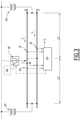
- FIG 1 schematically illustrates a possible embodiment of a control system according to the invention, indicated therein by the overall reference number 100, which is suitable to monitor the integrity of the two rails A and B of a railway track, indicated in figure 1 by the reference number 1.
- the control system 100 comprises at least:
- the at least one control and processing unit 30 is configured to calculate:
- the at least one control and processing unit 30 is further configured to calculate the difference between the first and second values calculated and to generate a control signal S c indicative of a defective part along one of the first and second rails A, B if the difference calculated exceeds a predetermined threshold.
- the control signal S c can be sent for example, via transmissions cables 35, or via a wireless device, such as the exemplary one illustrated in figure 1 by the reference number 36, towards a remote control center overseeing an entire railway line to which the monitored railway track 1 belongs to.
- each of the first, second, third and fourth sensors 10, 11, 20 and 21 can provide the respective signals to the at least one control and processing unit 30, via a cabled connections 15 or in a wireless manner.
- the first and second sensors 10 and 11 are magnetic field sensors configured to sense values indicative of an actual magnetic field generated around the first rail A by a current I A flowing along the first rail A itself.
- the third and fourth sensors 20 and 21 are magnetic field sensors configured to sense values indicative of an actual magnetic field generated around the second rail B by a current I B flowing along the second rail B itself.
- the magnetic field lines around the rails A or B are schematically represented in figure 2 by the arrows 5.
- the first sensor 10 operatively associated to the first rail A and the third sensor 20 operatively associated to the second rail B are substantially equal to each other; in turn, the second sensor 11 operatively associated to the first rail A and the fourth sensor 21 operatively associated to the second rail B are substantially equal to each other and of a type different from the first and third sensors 10 and 20.
- a first couple is based on a first type of physical properties or detecting technology in order to detect a parameter indicative of the actual current flowing in the rails A and B
- a second couple is based on a second type of physical properties or detecting technology in order to detect a parameter indicative of the actual current flowing in the rails A and B.
- the first and second parameters detected are the same, i.e. the intensity of the magnetic fields generated around the first rail A and correspondingly around the second rail B by the current I A flowing along the first rail A and respectively the current I B flowing along the second rail B.
- the first sensor 10 and the third sensor 20 are Hall-effect sensors.
- the second sensor 11 and the fourth sensor 21 are magneto-resistive sensors.
- each of the first, second, third and fourth sensors 10, 11, 20 and 21, can be positioned inside a respective casing, illustrated schematically in figure 1 by the reference number 25; for instance, each casing 25 can be conveniently dust and water proof and, depending on the applications, it can be also realized with a material suitable to shield external disturbing magnetic fields if needed.
- one or more of, preferably all the first, second third and fourth magnetic field sensors 10, 11, 20 and 21 are positioned each inside a respective magnetic flux concentrator, schematically indicated in figure 1 by the reference number 26.
- control system 100 comprises a control station 50 housing inside the at least one control and processing unit 30.
- control station 50 is positioned along the railway track 1, for example substantially at the same position where the first, second, third and fourth sensors 10, 11, 20 and 21 are positioned.
- the at least one control and processing unit 30 and the associated first, second, third and fourth sensors 10, 11, 20 and 21 can be supplied via power derived from the catenary line 51 itself; the same applies if the railway track 1 is powered by an AC source.
- the control station 50 comprises a power harvesting system 52, comprising for example one or more solar panels and related electronics, which is configured to harvest power, e.g. for powering the at least one processing unit 30 and also the associated first, second, third and fourth sensors 10, 11, 20 and 21.
- a power harvesting system 52 comprising for example one or more solar panels and related electronics, which is configured to harvest power, e.g. for powering the at least one processing unit 30 and also the associated first, second, third and fourth sensors 10, 11, 20 and 21.
- the first, second, third and fourth sensors 10, 11, 20 and 21 may comprise or be coupled with dedicated power harvesting devices configured to harvest power and supply each one or more of such sensors.
- control system 100 further comprises at least one test device 40 which is positioned along the railway track 1 and is configured to generate a test current to be injected inside the first and second rails A, B of the railway track 1 in order to monitor their integrity.
- test device 40 can be housed also inside the control station 50.
- the currents injected in the rails A and B by the test device 40 are those generating the magnetic fields detected by the first, second, third and fourth sensors indicated by the reference numbers 80, 81, 90 and 91 whose signals are then received by the at least control and processing unit 30 and properly processed, as previously described, in order to verify any defective part present along the first rail A or the second rail B.
- Each sensor 80, 81, 90 and 91 can be a single sensor of the same kind as 10, 11, 20 or 21 if redundancy is not required; otherwise for each of sensor 80, 81, 90 and 91 for example a couple of a Hall effect sensor and a magnetoresistive sensor can be used, since it is not known "a priori" in which direction relative to power stations 101 the test current will flow; hence, in this last case a total of eight sensors will be used.
- test device 40 can be realized according to various possible circuital schemes, per se known or readily available to those skilled in the art, and thus not described herein in further details, according to two main reference schemes different from each other based on the fact whether the test device 40 is used in a railway track which is already electrified and therefore a voltage source is available or not, in which case the test device 40 comprises also an own power generator.
- test device can be realized as a variant of a buck or buck-boost high frequency switching power converter, configured to output a current, as for example illustrated in figure 4 , where there is depicted a circuital exemplary embodiment for such test device 40.
- the upper switch 41 is PWM-modulated via a pulse generator or PWM modulator 42 so that the average current injected in the rails A and B is maintained at a certain level.
- the current comes from a remote traction power station through the catenary line 51, and returns to it through the rails A and B, in particular one half for each rail.
- the duty cycle of the switch 41 is kept very low to keep conduction losses at a minimum, and to use a high frequency current transformer 43 which is connected in series with an inductor 44 to sense the current and use the relative signal S F as feedback for the pulse generator or PWM modulator 42.
- the switch 41 can be realized with an appropriate cascade connection of high voltage, low power SiC IGBT or Mosfet, of any suitable type currently available on the market, connected in series to the current transformer 43 and the inductor 44, in order to realize the switch 41.
- diodes 45 are connected in parallel to the assembly formed by the serial connection of the inductor 44 and the transformer 43.
- Diodes 45 are an appropriate cascade connection of high voltage SiC diodes of any suitable type currently available on the market.
- the reference signal for the PWM modulator 42 can be a fixed one, or - better - a low frequency coded one, so that the injected current can vary between two or more levels, following a predefined pattern or a pattern generated by the electronics of the associated detection system.
- test current generated in this way is equivalent to the current drawn by the train; the currents in the rails will be measured by the two pair of sensors and their differential evaluated to asses if the rails are in good conditions or not.
- the power needed to generate the currents to be injected into the rails A and B can be provided for example by one traction power station 101 used for powering the track 1 itself; in such cases, the test device 40 can be placed along the railway track 1 in the centre of the electric "line" between two traction power stations 101, as illustrated in figure 3 .
- test device 40 can comprise an own power harvesting unit, indicated schematically in figure 3 by the dotted box 48, which is configured to harvest and store power to be used for self-powering, or it can be powered by the power harvesting system 52 of the control station 50.
- an own power harvesting unit indicated schematically in figure 3 by the dotted box 48, which is configured to harvest and store power to be used for self-powering, or it can be powered by the power harvesting system 52 of the control station 50.
- the test device 40 can be conveniently used to monitor the integrity of the rails A and B of a railway track 1, either when the railway track 1 is part of a non-electrified line, and/or where the majority of trains travelling along the track 1 are not electric ones, and/or there are long intervals of time without passages of trains.
- test device 40 allows performing monitoring of the rails with any sufficient frequency of monitoring tests necessary for example to meet SIL4-type requirements.
- the at least one control and processing unit 30 comprises a first control and processing unit 31 and a second control and processing unit 32, schematically represented in figure 1 by the reference numbers 31 and 32, respectively.
- the first control and processing unit 31 is arranged to be operatively connected to and receive the signals indicative of the corresponding magnetic field detected from one of the first and second sensors 10 and 11, and from one of the third and fourth sensors 20, 21 of different type
- the second control and processing unit 32 is arranged to be operatively connected to and receive signals indicative of the corresponding magnetic field detected from the other one of the first and second sensors 10, 11 and from the other one of the third and fourth sensors 20 and 21 having a different type.
- the first control and processing unit 31 can receive the signals S1 det and S4de, from the Hall-effect sensor 10 and the magneto-resistive sensor 21, while the second control and processing unit 31 can receive the signals S2 det and S3 det from the magneto-resistive sensor 11 and the Hall-effect sensor 20.
- one of the first and second control and processing units 31 and 32 can receive the signals provided by the Hall-effect sensors, and the other one can receive only the signals from the magneto-resistive sensors.
- the presence of the two control and processing units 31 and 32 improves redundancy, reliability and robustness of the control system 100.
- the other ones e.g. the magneto-resistive sensors will continue to detect the magnetic fields correctly, and at least one of the control and processing units 31 and 32, exchanging data between them, would be able to detect anyhow the presence of a defective part on a rail A or B, and generate a corresponding control signal S C .
- the two control and processing units 31 and 32 can be mutually coordinated to follow an appropriate and coordinated decisional process in order to solve any conflicting computation between them and properly discriminate among inconsistent detections, due for example to an actual external perturbation versus an actual malfunctioning of any sensor; for example, references values for the currents I A and I B can be prerecorded and taken as reference, for example on the basis of a nominal behavior for the railway track 1, or based on precalibration/autocalibration tests, or on periodic calibration tests executed injecting known currents, e.g. via the test device 40.
- FIG 5 there is schematically illustrated a method 200 for monitoring the integrity of the rails A, B of a railway track 1, which can be implemented for example by a control system as previously described.
- the method 200 comprises at least the following steps:
- detecting 210 and 220 can be executed in parallel to each other or in whatever suitable sequence.
- the method 200 can implement all steps and sub-steps corresponding to the execution of the various functionalities and performances described above for the control system 100, which are not hereby replicated for the sake of conciseness.
- control system 100 and method 200 according to the present invention achieve the intended aim and objects, since they allow detecting, timely and precisely, the presence of a potentially defective part of any part of a rail, according to a solution having an increased reliability and which improves therefore the overall safety of railway operations along the railway track 1 thus monitored.
- control system 100 may comprise a plurality of control stations 50 distributed at a certain distance from each other along a railway line and each of the control station can be associated with two couples of sensors of different type as previously described;
- control and processing unit 30, or each of the two control and processing units 31 and 32 can be constituted by, or comprise, any suitable processor-based device, e.g. a processor of a type commercially available, suitably programmed and provided to the extent necessary with circuitry, in order to perform the innovative functionalities devised for the control system 100 according to the present invention.
Landscapes
- Engineering & Computer Science (AREA)
- Mechanical Engineering (AREA)
- Automation & Control Theory (AREA)
- Health & Medical Sciences (AREA)
- Biomedical Technology (AREA)
- General Health & Medical Sciences (AREA)
- Train Traffic Observation, Control, And Security (AREA)
Priority Applications (1)
| Application Number | Priority Date | Filing Date | Title |
|---|---|---|---|
| EP20305986.0A EP3964420A1 (de) | 2020-09-07 | 2020-09-07 | Steuerungssystem und verfahren zur überwachung der unversehrtheit der schienen eines eisenbahngleises |
Applications Claiming Priority (1)
| Application Number | Priority Date | Filing Date | Title |
|---|---|---|---|
| EP20305986.0A EP3964420A1 (de) | 2020-09-07 | 2020-09-07 | Steuerungssystem und verfahren zur überwachung der unversehrtheit der schienen eines eisenbahngleises |
Publications (1)
| Publication Number | Publication Date |
|---|---|
| EP3964420A1 true EP3964420A1 (de) | 2022-03-09 |
Family
ID=72561737
Family Applications (1)
| Application Number | Title | Priority Date | Filing Date |
|---|---|---|---|
| EP20305986.0A Pending EP3964420A1 (de) | 2020-09-07 | 2020-09-07 | Steuerungssystem und verfahren zur überwachung der unversehrtheit der schienen eines eisenbahngleises |
Country Status (1)
| Country | Link |
|---|---|
| EP (1) | EP3964420A1 (de) |
Cited By (1)
| Publication number | Priority date | Publication date | Assignee | Title |
|---|---|---|---|---|
| CN115758528A (zh) * | 2022-11-18 | 2023-03-07 | 中国铁路设计集团有限公司 | 铁路起拨道整治方案综合优化计算方法 |
Citations (2)
| Publication number | Priority date | Publication date | Assignee | Title |
|---|---|---|---|---|
| DE102006009962B3 (de) * | 2005-12-23 | 2007-05-31 | Areva Np Gmbh | Verfahren und Einrichtung zum Überwachen eines Gleises |
| US20110006167A1 (en) * | 2009-07-07 | 2011-01-13 | Ron Tolmei | Fail-safe safety system to detect and annunciate fractured running rails in electrically propelled transit systems |
-
2020
- 2020-09-07 EP EP20305986.0A patent/EP3964420A1/de active Pending
Patent Citations (2)
| Publication number | Priority date | Publication date | Assignee | Title |
|---|---|---|---|---|
| DE102006009962B3 (de) * | 2005-12-23 | 2007-05-31 | Areva Np Gmbh | Verfahren und Einrichtung zum Überwachen eines Gleises |
| US20110006167A1 (en) * | 2009-07-07 | 2011-01-13 | Ron Tolmei | Fail-safe safety system to detect and annunciate fractured running rails in electrically propelled transit systems |
Non-Patent Citations (1)
| Title |
|---|
| WEI YANG ET AL: "A residual current measurement method with a combination of MR and Hall Effect sensors", APPLIED MEASUREMENTS FOR POWER SYSTEMS (AMPS), 2010 IEEE INTERNATIONAL WORKSHOP ON, IEEE, PISCATAWAY, NJ, USA, 22 September 2010 (2010-09-22), pages 27 - 30, XP031780642, ISBN: 978-1-4244-7372-4 * |
Cited By (2)
| Publication number | Priority date | Publication date | Assignee | Title |
|---|---|---|---|---|
| CN115758528A (zh) * | 2022-11-18 | 2023-03-07 | 中国铁路设计集团有限公司 | 铁路起拨道整治方案综合优化计算方法 |
| CN115758528B (zh) * | 2022-11-18 | 2023-09-29 | 中国铁路设计集团有限公司 | 铁路起拨道整治方案综合优化计算方法 |
Similar Documents
| Publication | Publication Date | Title |
|---|---|---|
| US8294391B2 (en) | Moving body system and method of determining initial position of moving body | |
| US6371417B1 (en) | Railway wheel counter and block control systems | |
| CN101750218A (zh) | 监测轨道车辆磁力制动器的装置和方法 | |
| JP6547165B2 (ja) | チェーン伸長を測定するためのリラクタンス式チェーンセンサ及び測定方法 | |
| EP3964420A1 (de) | Steuerungssystem und verfahren zur überwachung der unversehrtheit der schienen eines eisenbahngleises | |
| RU2495773C2 (ru) | Способ контроля рельсовых тормозов | |
| EP3825203B1 (de) | System, verfahren und eisenbahnfahrzeug zur überwachung eines dritte schiene systems einer eisenbahnstrecke | |
| GB2460515A (en) | Detecting an exciter fault in a brushless generator | |
| PL182366B1 (pl) | Sposób i urzadzenie do wykrywania polozenia przestawnych czesci zwrotnicy PL | |
| CN1537234A (zh) | 电路布置和一种电路的检验方法 | |
| US20060250126A1 (en) | Device for creating a region which is substantially free of magnetic field, surrounded by a region with a magnetic field gradient | |
| US7292144B2 (en) | Apparatus and method for contact-less switching | |
| US10928454B2 (en) | Device for diagnosing a mechanical system which is driven by means of an electric drive motor | |
| EP2216229A2 (de) | Vorrichtung und Verfahren zu Überwachung von isolierten Schienenstößen | |
| JP5420181B2 (ja) | 磁気浮上式鉄道の地上コイル異状検知センサ用電源装置 | |
| RU2406624C1 (ru) | Система электроснабжения электрифицированных железных дорог переменного тока | |
| KR20090050669A (ko) | 송/배전선로용 사고위치 검출장치 | |
| CN110687401A (zh) | 铁路上接触网的故障检测系统和方法 | |
| US20210116509A1 (en) | Method and apparatus for monitoring the wear of a long stator linear motor system | |
| EP3718853A1 (de) | Verfahren, system und fahrzeug zur lokalisierung defekter teile von energieversorgungssystemen in schienenanwendungen | |
| JP6947306B2 (ja) | レール破断検知装置及びレール破断結果管理システム | |
| ATE188929T1 (de) | Detektiergerät für eine kurzschlussverbindung für einen gleisabschnitt | |
| RU2519473C1 (ru) | Способ измерения и контроля намагниченности рельсов | |
| RU199010U1 (ru) | Ленточный конвейер | |
| CN113960487B (zh) | 轨道电路绝缘短路故障快速修复方法 |
Legal Events
| Date | Code | Title | Description |
|---|---|---|---|
| PUAI | Public reference made under article 153(3) epc to a published international application that has entered the european phase |
Free format text: ORIGINAL CODE: 0009012 |
|
| STAA | Information on the status of an ep patent application or granted ep patent |
Free format text: STATUS: THE APPLICATION HAS BEEN PUBLISHED |
|
| STAA | Information on the status of an ep patent application or granted ep patent |
Free format text: STATUS: REQUEST FOR EXAMINATION WAS MADE |
|
| AK | Designated contracting states |
Kind code of ref document: A1 Designated state(s): AL AT BE BG CH CY CZ DE DK EE ES FI FR GB GR HR HU IE IS IT LI LT LU LV MC MK MT NL NO PL PT RO RS SE SI SK SM TR |
|
| 17P | Request for examination filed |
Effective date: 20220225 |
|
| RBV | Designated contracting states (corrected) |
Designated state(s): AL AT BE BG CH CY CZ DE DK EE ES FI FR GB GR HR HU IE IS IT LI LT LU LV MC MK MT NL NO PL PT RO RS SE SI SK SM TR |
|
| P01 | Opt-out of the competence of the unified patent court (upc) registered |
Effective date: 20230823 |
|
| RAP1 | Party data changed (applicant data changed or rights of an application transferred) |
Owner name: ALSTOM HOLDINGS |
|
| STAA | Information on the status of an ep patent application or granted ep patent |
Free format text: STATUS: EXAMINATION IS IN PROGRESS |
|
| 17Q | First examination report despatched |
Effective date: 20240624 |