EP3963732B1 - Verfahren und vorrichtung zur verbesserung auf basis von untergruppenanzeige für auf zwei codebüchern basierende csi-meldung - Google Patents
Verfahren und vorrichtung zur verbesserung auf basis von untergruppenanzeige für auf zwei codebüchern basierende csi-meldung Download PDFInfo
- Publication number
- EP3963732B1 EP3963732B1 EP20717208.1A EP20717208A EP3963732B1 EP 3963732 B1 EP3963732 B1 EP 3963732B1 EP 20717208 A EP20717208 A EP 20717208A EP 3963732 B1 EP3963732 B1 EP 3963732B1
- Authority
- EP
- European Patent Office
- Prior art keywords
- csi
- layer
- matrix
- parameter
- indicator
- Prior art date
- Legal status (The legal status is an assumption and is not a legal conclusion. Google has not performed a legal analysis and makes no representation as to the accuracy of the status listed.)
- Active
Links
- 238000000034 method Methods 0.000 title claims description 48
- 239000011159 matrix material Substances 0.000 claims description 144
- 239000013598 vector Substances 0.000 claims description 130
- 230000001934 delay Effects 0.000 claims description 52
- 230000005540 biological transmission Effects 0.000 claims description 35
- 230000001419 dependent effect Effects 0.000 claims description 13
- 230000010287 polarization Effects 0.000 description 25
- 238000012545 processing Methods 0.000 description 18
- 230000004044 response Effects 0.000 description 9
- 238000004364 calculation method Methods 0.000 description 7
- 238000004891 communication Methods 0.000 description 7
- 238000004590 computer program Methods 0.000 description 6
- 125000004122 cyclic group Chemical group 0.000 description 6
- 238000013507 mapping Methods 0.000 description 6
- 238000005516 engineering process Methods 0.000 description 5
- 230000009467 reduction Effects 0.000 description 5
- 230000008901 benefit Effects 0.000 description 4
- 230000006835 compression Effects 0.000 description 4
- 238000007906 compression Methods 0.000 description 4
- 238000013459 approach Methods 0.000 description 3
- 230000007423 decrease Effects 0.000 description 2
- 230000006870 function Effects 0.000 description 2
- 230000002688 persistence Effects 0.000 description 2
- 238000013139 quantization Methods 0.000 description 2
- 230000011664 signaling Effects 0.000 description 2
- 230000003247 decreasing effect Effects 0.000 description 1
- 238000010586 diagram Methods 0.000 description 1
- PCHJSUWPFVWCPO-UHFFFAOYSA-N gold Chemical compound [Au] PCHJSUWPFVWCPO-UHFFFAOYSA-N 0.000 description 1
- 239000010931 gold Substances 0.000 description 1
- 229910052737 gold Inorganic materials 0.000 description 1
- 230000009466 transformation Effects 0.000 description 1
Images


Classifications
-
- H—ELECTRICITY
- H04—ELECTRIC COMMUNICATION TECHNIQUE
- H04B—TRANSMISSION
- H04B7/00—Radio transmission systems, i.e. using radiation field
- H04B7/02—Diversity systems; Multi-antenna system, i.e. transmission or reception using multiple antennas
- H04B7/04—Diversity systems; Multi-antenna system, i.e. transmission or reception using multiple antennas using two or more spaced independent antennas
- H04B7/06—Diversity systems; Multi-antenna system, i.e. transmission or reception using multiple antennas using two or more spaced independent antennas at the transmitting station
- H04B7/0613—Diversity systems; Multi-antenna system, i.e. transmission or reception using multiple antennas using two or more spaced independent antennas at the transmitting station using simultaneous transmission
- H04B7/0615—Diversity systems; Multi-antenna system, i.e. transmission or reception using multiple antennas using two or more spaced independent antennas at the transmitting station using simultaneous transmission of weighted versions of same signal
- H04B7/0619—Diversity systems; Multi-antenna system, i.e. transmission or reception using multiple antennas using two or more spaced independent antennas at the transmitting station using simultaneous transmission of weighted versions of same signal using feedback from receiving side
- H04B7/0658—Feedback reduction
- H04B7/0663—Feedback reduction using vector or matrix manipulations
-
- H—ELECTRICITY
- H04—ELECTRIC COMMUNICATION TECHNIQUE
- H04B—TRANSMISSION
- H04B7/00—Radio transmission systems, i.e. using radiation field
- H04B7/02—Diversity systems; Multi-antenna system, i.e. transmission or reception using multiple antennas
- H04B7/04—Diversity systems; Multi-antenna system, i.e. transmission or reception using multiple antennas using two or more spaced independent antennas
- H04B7/06—Diversity systems; Multi-antenna system, i.e. transmission or reception using multiple antennas using two or more spaced independent antennas at the transmitting station
- H04B7/0613—Diversity systems; Multi-antenna system, i.e. transmission or reception using multiple antennas using two or more spaced independent antennas at the transmitting station using simultaneous transmission
- H04B7/0615—Diversity systems; Multi-antenna system, i.e. transmission or reception using multiple antennas using two or more spaced independent antennas at the transmitting station using simultaneous transmission of weighted versions of same signal
- H04B7/0619—Diversity systems; Multi-antenna system, i.e. transmission or reception using multiple antennas using two or more spaced independent antennas at the transmitting station using simultaneous transmission of weighted versions of same signal using feedback from receiving side
- H04B7/0621—Feedback content
- H04B7/0626—Channel coefficients, e.g. channel state information [CSI]
-
- H—ELECTRICITY
- H04—ELECTRIC COMMUNICATION TECHNIQUE
- H04B—TRANSMISSION
- H04B7/00—Radio transmission systems, i.e. using radiation field
- H04B7/02—Diversity systems; Multi-antenna system, i.e. transmission or reception using multiple antennas
- H04B7/04—Diversity systems; Multi-antenna system, i.e. transmission or reception using multiple antennas using two or more spaced independent antennas
- H04B7/0413—MIMO systems
- H04B7/0417—Feedback systems
-
- H—ELECTRICITY
- H04—ELECTRIC COMMUNICATION TECHNIQUE
- H04B—TRANSMISSION
- H04B7/00—Radio transmission systems, i.e. using radiation field
- H04B7/02—Diversity systems; Multi-antenna system, i.e. transmission or reception using multiple antennas
- H04B7/04—Diversity systems; Multi-antenna system, i.e. transmission or reception using multiple antennas using two or more spaced independent antennas
- H04B7/0413—MIMO systems
- H04B7/0456—Selection of precoding matrices or codebooks, e.g. using matrices antenna weighting
- H04B7/0478—Special codebook structures directed to feedback optimisation
-
- H—ELECTRICITY
- H04—ELECTRIC COMMUNICATION TECHNIQUE
- H04B—TRANSMISSION
- H04B7/00—Radio transmission systems, i.e. using radiation field
- H04B7/02—Diversity systems; Multi-antenna system, i.e. transmission or reception using multiple antennas
- H04B7/04—Diversity systems; Multi-antenna system, i.e. transmission or reception using multiple antennas using two or more spaced independent antennas
- H04B7/06—Diversity systems; Multi-antenna system, i.e. transmission or reception using multiple antennas using two or more spaced independent antennas at the transmitting station
- H04B7/0613—Diversity systems; Multi-antenna system, i.e. transmission or reception using multiple antennas using two or more spaced independent antennas at the transmitting station using simultaneous transmission
- H04B7/0615—Diversity systems; Multi-antenna system, i.e. transmission or reception using multiple antennas using two or more spaced independent antennas at the transmitting station using simultaneous transmission of weighted versions of same signal
- H04B7/0619—Diversity systems; Multi-antenna system, i.e. transmission or reception using multiple antennas using two or more spaced independent antennas at the transmitting station using simultaneous transmission of weighted versions of same signal using feedback from receiving side
- H04B7/0621—Feedback content
- H04B7/063—Parameters other than those covered in groups H04B7/0623 - H04B7/0634, e.g. channel matrix rank or transmit mode selection
-
- H—ELECTRICITY
- H04—ELECTRIC COMMUNICATION TECHNIQUE
- H04B—TRANSMISSION
- H04B7/00—Radio transmission systems, i.e. using radiation field
- H04B7/02—Diversity systems; Multi-antenna system, i.e. transmission or reception using multiple antennas
- H04B7/04—Diversity systems; Multi-antenna system, i.e. transmission or reception using multiple antennas using two or more spaced independent antennas
- H04B7/06—Diversity systems; Multi-antenna system, i.e. transmission or reception using multiple antennas using two or more spaced independent antennas at the transmitting station
- H04B7/0613—Diversity systems; Multi-antenna system, i.e. transmission or reception using multiple antennas using two or more spaced independent antennas at the transmitting station using simultaneous transmission
- H04B7/0615—Diversity systems; Multi-antenna system, i.e. transmission or reception using multiple antennas using two or more spaced independent antennas at the transmitting station using simultaneous transmission of weighted versions of same signal
- H04B7/0619—Diversity systems; Multi-antenna system, i.e. transmission or reception using multiple antennas using two or more spaced independent antennas at the transmitting station using simultaneous transmission of weighted versions of same signal using feedback from receiving side
- H04B7/0636—Feedback format
- H04B7/0639—Using selective indices, e.g. of a codebook, e.g. pre-distortion matrix index [PMI] or for beam selection
-
- H—ELECTRICITY
- H04—ELECTRIC COMMUNICATION TECHNIQUE
- H04L—TRANSMISSION OF DIGITAL INFORMATION, e.g. TELEGRAPHIC COMMUNICATION
- H04L25/00—Baseband systems
- H04L25/02—Details ; arrangements for supplying electrical power along data transmission lines
- H04L25/0202—Channel estimation
Definitions
- the present disclosure relates to the field of wireless communications, and in particular, to methods and apparatuses for efficient feedback reporting for at least a New Radio- (NR-) based wireless communication network system, which feedback reporting includes Channel State Information (CSI).
- NR- New Radio-
- CSI Channel State Information
- downlink (DL) and uplink (UL) signals convey data signals, control signals comprising DL control information (DCI) and/or uplink control information (UCI), and a number of reference signals (RSs) used for different purposes.
- DCI DL control information
- UCI uplink control information
- RSs reference signals
- a radio network node or a radio base station or a gNodeB (or gNB or gNB/TRP (Transmit Reception Point)) transmits data and DCI through the so-called physical downlink shared channel (PDSCH) and the physical downlink control channel (PDCCH), respectively.
- PDSCH physical downlink shared channel
- PDCCH physical downlink control channel
- a UE transmits data and UCI through the so-called physical uplink shared channel (PUSCH) and physical uplink control channel (PUCCH), respectively.
- the DL or UL signal(s) of the gNB respectively the user equipment (UE or a radio device) may contain one or multiple types of RSs including a channel state information RS (CSI-RS), a demodulation RS (DM-RS), and a sounding RS (SRS).
- CSI-RS channel state information RS
- DM-RS demodulation RS
- SRS sounding RS
- the CSI-RS (SRS) is transmitted over a DL (UL) system bandwidth part and used at the UE (gNB) for CSI acquisition.
- the DM-RS is transmitted only in a bandwidth part of the respective PDSCH/PUSCH and used by the UE/gNB for data demodulation.
- MIMO multi-input multi-output
- the current third Generation Partnership Project Release 15 specification (3GPP Rel. 15) therefore provides a comprehensive framework for CSI reporting.
- the CSI is acquired in a first step at the UE based on received CSI-RS signals transmitted by the gNB.
- the UE determines in a second step based on the estimated channel matrix a precoding matrix from a predefined set of matrices called 'codebook'.
- the selected precoding matrix is reported in a third step in the form of a precoding matrix identifier (PMI) and rank identifier (RI) to the gNB.
- PMI precoding matrix identifier
- RI rank identifier
- Type-I and Type-II for CSI reporting, where both types rely on a dual-stage (i.e., two components) W 1 W 2 codebook.
- the first codebook, or the so-called first stage precoder, W 1 is used to select a number of beam vectors from a Discrete Fourier Transform-based (DFT-based) matrix which is also called the spatial codebook.
- the second codebook, or the so-called second stage precoder, W 2 is used to combine the selected beams.
- W 2 contains phase-only combining coefficients and complex combing coefficients, respectively.
- Type-II CSI reporting W 2 is calculated on a subband basis such that the number of columns of W 2 depends on the number of configured subbands.
- a subband refers to a group of adjacent physical resource blocks (PRBs).
- PRBs physical resource blocks
- the matrix W 1 l ⁇ C PN 1 N 2 ⁇ 2 U is the wideband first-stage precoder containing 2 U spatial beams for both polarizations which are identical for all S subbands, and W A is a diagonal matrix containing 2 U wideband amplitudes associated with the 2 U spatial beams, and ⁇ 2 ( s ) is the second-stage precoder containing 2 U subband (subband amplitude and phase) complex frequency-domain combining coefficients associated with the 2 U spatial beams for the s-th subband.
- a communication device or a radio device or a user equipment (UE) and a method therein for providing a channel state information (CSI) feedback in a wireless communication system including at least the UE and a gNB or a radio network node.
- the UE comprising a processor and a memory, said memory containing instructions executable by said processor whereby said UE is operative/configured to perform any one of the method steps according to any one of claims 1-11.
- a network node or gNB comprising a processor and a memory, said memory containing instructions executable by said processor whereby said gNB is operative/configured to perform method steps as will be described.
- the method performed by the UE includes: receiving from a network node, gNB, a radio signal via a Multiple Input Multiple Output (MIMO) channel, wherein the radio signal contains at least one DownLink (DL) reference signal according to a DL reference signal configuration; estimating said MIMO channel based on said received at least one DL reference signal for configured subbands ( N 3 ); calculating a precoder matrix or a Channel State Information (CSI) matrix for a number of antenna ports of the gNB and configured subbands; the precoder matrix being based on a first codebook and on a second codebook and a set of combining coefficients for complex scaling/combining one or more of vectors selected from the first codebook and the second codebook; where, the first codebook contains one or more transmit-side spatial beam components of the precoder matrix, the second codebook contains one or more delay components of the precoder matrix or CSI matrix.
- MIMO Multiple Input Multiple Output
- the method further comprises, determining a common delay domain (CDD) basis subset of the selected vectors associated with the delay components across all layers of the precoder matrix or CSI matrix, wherein the CDD basis subset is defined by a parameter D representing the number of elements of the CDD basis subset, and a parameter D in representing the first index of the D delay vectors from the second codebook, wherein the value range of the parameter D in is reduced from N 3 to D values; and reporting, to the gNB, a CSI feedback report and/or a Precoder matrix Indicator, PMI and/or a PMI/Rank Indicator (PMI/RI) used to indicate the precoder matrix or the CSI matrix for the configured antenna ports and configured subbands; wherein the selected vectors from the CDD basis subset are indicated in the reporting, for each layer, by a layer-specific delay domain (LDD) basis subset indicator; and the parameter D in is reported to the gNB.
- CDD common delay domain
- a method performed by a network node or a gNB comprising: transmitting, to a UE, a radio signal via a MIMO channel, wherein the radio signal contains at least one DL, reference signal according to a DL reference signal configuration; for enabling the UE to: estimate said MIMO channel based on said received at least one DL reference signal for configured subbands, N 3 , calculate a precoder matrix or a CSI matrix for a number of antenna ports of the gNB and configured subbands; the precoder matrix being based on a first codebook and on a second codebook and a set of combining coefficients for complex scaling/combining one or more vectors selected from the first codebook and the second codebook; where the first codebook contains one or more transmit-side spatial beam components of the precoder matrix or CSI matrix, the second codebook contains one or more delay components of the precoder matrix or CSI matrix; determine a CDD basis subset of the selected vectors associated with the
- An advantage with embodiments herein is to provide a feedback compression scheme for a second stage precoder that reduces the feedback overhead for reporting precoder coefficients.
- Another advantage of the present embodiments is to provide several schemes for low-feedback overhead reporting for spatial domain and delay domain basis indicators and delay-domain combining coefficients.
- the embodiments herein provide a feedback compression scheme for the second stage precoder W 2 that drastically reduces the feedback overhead for reporting, by the UE, the precoder coefficients.
- the UE comprises a transceiver which is configured to receive from a transmitter a radio signal via a MIMO channel, where the radio signal contains DL reference signals (e.g., CSI-RS) according to a DL reference signal configuration, and the UE, by means of a processor is operative to: estimate the MIMO channel between the gNB and the UE based on the received DL reference signals for the configured subbands, calculate, based on a performance metric, a precoder matrix or a CSI matrix, for a number of gNB' antenna/ DL RS ports and configured subbands, that is based on two codebooks and a set of combining coefficients for complex scaling/combining the one or more of the vectors selected from the first and second codebook, where the first codebook contains one or more transmit-side spatial beam components of the CSI matrix, and the second codebook contains one or more delay components of the CSI matrix, and report the CSI feedback/PMI and RI to indicate the precoder matrix CSI matrix per layer for
- precoder matrix and the CSI matrix are used interchangeably meaning that they are equivalent.
- the first codebook comprises a DFT matrix or oversampled DFT-matrix of size N 1 N 2 ⁇ O 1,1 N 1 O 12 N 2 containing the spatial beam components (N 1 N 2 ⁇ 1 vectors) of the precoder matrix.
- N 1 and N 2 refer to the number of antenna ports of the same polarization in the first and second dimension of the antenna array, respectively.
- N 1 and N 2 are both greater than 1, whereas for a linear (1D (onedimensional) either N 1 or N 2 is one.
- the total number of antenna ports for a dual-polarized antenna array is 2 N 1 N 2 .
- O 1,1 ⁇ ⁇ 1,2,3,.. ⁇ and O 1,2 ⁇ ⁇ 1,2,3,.. ⁇ refer to the oversampling factors of the codebook matrix with respect to the first and second dimension, respectively.
- the first codebook comprises a set of P CSI-RS /2 ⁇ 1 column vectors, where the m-th column vector contains a single 1 at the m-th position of the vector and zeros elsewhere.
- the parameter P CSI-RS denotes the total number of CSI-RS ports used by the UE for channel estimation and precoder coefficient calculation.
- This codebook may be called as port selection codebook and is used when a beamforming operation is performed by the gNB such that each antenna port corresponds to a beam-formed port.
- the parameter P CSI-RS may be higher-layer configured by the gNB e.g. using a RRC (Radio Resource Control) signaling.
- RRC Radio Resource Control
- N 3 refers to the configured number of subbands
- Each DFT vector models a linear phase increase over the N 3 subbands, and each vector is therefore associated with a delay in the transformed (delay) domain.
- the DFT vectors of the second codebook are referred to as delay vectors or simply delays, and the combining coefficients used for the complex scaling/combining of the one or more of the vectors selected from the first and second codebook as delay-domain combining coefficients.
- the UE is configured to determine a rank indicator (RI) from the MIMO channel estimate and to configure the CSI matrix (or precoder matrix) with RI layers.
- the UE may be configured to select a subset of U ( l ) beam vectors from the first codebook, a subset of D ( l ) delay vectors from the second codebook and 2 U ( l ) D ( l ) combining coefficients, and to indicate in the CSI report the selected RI and the selected beam and delay vectors and combining coefficients of the CSI matrix.
- the UE is configured to report for each layer of the CSI matrix a spatial domain (SD) basis indicator indicating the selected subset of U ( l ) beam vectors of the I-th layer and a delay domain (DD) basis indicator indicating the selected subset of D ( l ) delays vectors of the I-th layer.
- SD spatial domain
- DD delay domain
- the herein proposed two-codebook CSI reporting scheme (based on matrices G 1 l and G 2 l ) is based on precoding operations in the delay-domain instead of the frequency domain.
- the UE may exploit the sparsity of the 2 U ( l ) beam-formed channel impulse responses (obtained by combining the selected beam vectors b u l and the MIMO channel impulse response) when optimizing for the delay domain combining coefficients ⁇ p , u , d l .
- the precoding operation leads to an energy concentration of the MIMO channel impulse in both space and delay domain dimensions, such that each of the corresponding 2 U ( l ) beam-formed channel impulse response is characterized by only a few significant channel delays/taps.
- These channel delays are used by the UE for determining the delay domain combining coefficients ⁇ p , u , d l .
- the number of combining coefficients per layer to be reported reduces from 2 U ( l ) N 3 for the Rel.
- Type-II CSI single-codebook reporting scheme to 2 U ( l ) D ( l ) , where D ( l ) « N 3 , for the proposed two-codebook CSI reporting scheme.
- the UE is configured from the gNB with a CSI report configuration
- the CSI report configuration contains the higher-layer (e.g., RRC) parameter(s) U ( l ) and D ( l ) representing the number of beam vectors and delay vectors, respectively, for the I-th layer of the CSI matrix.
- RRC higher-layer
- the UE is configured from the gNB with a CSI report configuration
- the CSI report configuration contains the higher-layer (e.g., RRC) parameter(s) D ( l ) , representing the number of delays per beam for the I-th layer, used for the configuration of the CSI matrix (or precoder matrix).
- the number of configured delays D ( l ) per layer has a large influence on the feedback overhead for reporting the selected 2 ⁇ l U ( l ) D ( l ) combining coefficients for the layers.
- the UE may be configured with different number of delays D ( l ) per layer, or per layer-group (i.e., a subset of layers). In the following, some examples for the delay configuration are presented.
- the parameters ⁇ 1 and ⁇ 2 are either higher-layer configured or fixed by specification or reported by the UE. Examples of ⁇ 1 and ⁇ 2 are ⁇ t ⁇ 1 8 1 4 3 8 1 3 1 2 2 3 3 4 1 , t ⁇ 1,2 .
- the gNB configures a single parameter D (0) for the first layer, and the UE derives the parameter(s) D ( l ) , l > 0 for the remaining layers by e.g. a rule, although not necessarily.
- D ( l ) may be identical for the first three layers and different for the fourth layer, D (3) ⁇ D (0) or D (3) ⁇ D (0) .
- D ( l ) may be different for all layers, D (l+1) ⁇ D ( l ) , l ⁇ [0,2].
- a UE may be configured with a single parameter D which denotes the total number of delays across all layers.
- the UE may then report, to the gNB, the assigned number of delays to the gNB.
- the configuration of delays may be dependent on the rank (RI) of the CSI matrix.
- D ( l,r ) denote the number of delays for the l -th layer and the r-th rank.
- the number of delays per layer for RI ⁇ 2 may be identical.
- the number of delays of the l-th layer for RI ⁇ 4 may be identical to the number of delays of the I-th layer for RI ⁇ 1.
- D ( l,r ) denotes the number of delays per layer associated with each Rl, r ⁇ ⁇ 1,2,3,4 ⁇ .
- the number of delays per layer for RI > 2 may not be identical to the number of delays per layer for RI ⁇ 2.
- the number of delays per layer D ( l,r ) , ⁇ l, for RI > 2 may be derived from the number of delays of RI ⁇ 2.
- the UE is configured to select the values D ( l,r ) or D ( l ) or ⁇ i , i ⁇ ⁇ 0,1,2 ⁇ and report the selected values of D ( l,r ) or D ( l ) or ⁇ i , i ⁇ ⁇ 0,1,2 ⁇ .
- Examples for p ( l ) are p l ⁇ 1 8 1 4 3 8 1 3 1 2 2 3 3 4 .
- the gNB may signal parameter(s) p ( l ) for the configuration of the CSI matrix.
- the UE is configured to receive from the gNB the higher layer parameter N 3 , representing the number of configured subbands for the second codebook matrix.
- the number of subbands may depend on the number of CQI subbands N CQI (used for the calculation of the CQI) by a known rule.
- the higher layer parameter R may be a UE capability.
- a UE may have only a limited processing capability for the calculation of the CSI matrix, and it may not be able to apply large values of N 3 .
- the UE is configured from the gNB with a CSI report configuration
- the CSI report configuration contains the higher-layer (e.g., RRC) parameter(s) U ( l ) , representing the number of spatial beams for the I-th layer, used for the configuration of the CSI matrix.
- U may be given by a limited value range, e.g., U ⁇ ⁇ 2,4,6 ⁇ .
- the parameters ⁇ 1 and ⁇ 2 are either higher-layer configured or fixed by specification or reported by the UE.
- Examples of ⁇ 1 , ⁇ 2 and ⁇ 3 are ⁇ t ⁇ 1 8 1 4 3 8 1 3 1 2 2 3 3 4 1 , t ⁇ 1 2,3 .
- Configuring the UE with a large value of U enhances the performance but at the cost of increased feedback overhead. Therefore, the gNB may control the feedback overhead by limiting the large value of U only for certain Rl's. In other words, the configuration of spatial beams can be rank-dependent.
- the higher layer parameter U may be a UE capability.
- a UE may have only a limited processing capability for the calculation of the CSI matrix, and it may not be able to apply large values of U.
- a UE may be configured with a single parameter U which denotes the total number of spatial beams across all layers.
- the UE may then be configured to report the assigned number of spatial beams per layer to the gNB.
- the number of spatial beams for e layers ( e > 1) may be apriori known to the UE, and the UE may be configured with a single parameter U which denotes the total number of spatial beams across RI - e layers.
- the UE maybe configuredreport the assigned number of spatial beams for the RI - e layers to the gNB.
- a UE may be configured with one or more parameters, which denote(s) the total number of spatial beams across all layers in one or more subsets. Each subset may contain one or more number of layers.
- the UE then calculates the required number of spatial beams per layer ( U ( l ) ) based on any performance enhancement/feedback reduction criterion.
- the assigned number of spatial beams per layer may then be reported to the gNB.
- each of the 2 U ( l ) beams of the CSI matrix is associated with only a small number of channel delays.
- each beam may only be associated with a small number of delays/delay vectors from the selected D ( l ) -sized basis delay vector subset.
- This means the power of the combining coefficients of a beam may be concentrated at few delays such that some of the combining coefficients may have close to zero amplitude values. Since the close to zero-valued combining coefficients do not significantly affect the performance, the UE may be configured to indicate those coefficients in the CSI report and may not report them.
- the following embodiments provide proposals for the combining coefficient selection, indication and reporting in the CSI report.
- the UE is configured to select K ( l ) or less than K ( l ) non-zero combining coefficients for the I-th layer of the CSI matrix, to report the selected non-zero combining coefficients for all layers of the CSI matrix, and to indicate the selected combining coefficients in the CSI report.
- the selected non-zero coefficients for the I-th layer may be indicated by a 2 U ( l ) ⁇ D ( l ) -sized bitmap, where each bit in the bitmap is associated with a polarization index ( p ⁇ ⁇ 1,2 ⁇ ), beam index (0 ⁇ u ⁇ U ( l ) - 1) and delay index (0 ⁇ d ⁇ D ( l ) - 1).
- a "1" in the bitmap may indicate that the combining coefficient associated with the polarization index p , beam index u , and delay index d is non-zero, selected and reported by the UE.
- a "0" in the bitmap may indicate that the combining coefficient associated with the polarization index p , beam index u , and delay index d is zero and not reported by the UE.
- the UE may be configured by the gNB with the higher layer parameter(s) K ( l ) , representing the maximum number of non-zero coefficients the UE reports for the I-th layer of the CSI matrix.
- the UE may be configured with different or identical K ( l ) per layer, or per layer-group (i.e., a subset of layers).
- the parameter K (0) is configured for the first layer, and the parameters K ( l ) , l > 0 for the higher layers are derived by the UE by e.g. a known rule.
- the UE is configured by a single parameter K that denotes the total number of non-zero coefficients across all layers.
- the UE is configured by a single parameter K 1 that denotes the maximum number of non-zero combining coefficients for each layer.
- a UE may be configured to use a two-step approach to reduce the overall overhead for reporting the bitmaps of all layers.
- the joint bitmap may consist of Q g '1's, where a "1" in the joint bitmap represents an index of a reported non-zero coefficient in at least one or more of the individual bitmaps of the layers.
- the UE may report an indication of the indices of the selected non-zero combining coefficients associated with the joint bitmap. Different alternatives for the second step reporting are presented in the following.
- the UE reports a Q g -sized bitmap per layer.
- Each bit of the Q g -sized bitmap indicates an index of a reported non-zero combining coefficient for the layer in CSI part 2.
- the UE reports a Q g l - sized bitmap per layer, where Q g l denotes the number of 1's in the first D ( l ) columns and the first U ( l ) rows of the joint bitmap.
- Each bit of the Q g l -sized bitmap indicates an index of a reported non-zero combining coefficient for the layer in CSI part 2.
- the UE reports a ⁇ log 2 Q g l NZ l ⁇ -bit indicator per layer that indicates the indices of the reported non-zero combining coefficients for the layer.
- the UE reports a ⁇ log 2 Q g NZ l ⁇ -bit indicator per layer that indicates the indices of the reported non-zero combining coefficients for the layer.
- the UE reports a max l ⁇ log 2 Q g l NZ l ⁇ -bit indicator per layer that indicates the indices of the reported non-zero combining coefficients for the layer.
- the UE reports a max l ⁇ log 2 Q g NZ l ⁇ -bit indicator per layer that indicates the indices of the reported non-zero combining coefficients for the layer.
- the UE may be configured to report the number of '1's in the joint bitmap, i.e., the value of Q g l per layer, or layer group, in UCI part 1.
- the UE is configured to indicate the size of the second step bitmap(s), or the second step combinatorial bit indicator(s) in UCI part 1.
- the value of Q g may be indicated (e.g., by a ⁇ log 2 Q g ⁇ D g ⁇ bit indicator) in UCI part 1.
- the size(s) of the ⁇ log 2 Q g NZ l ⁇ -bit indicator(s) (e.g., the value of Q g ) may be indicated in UCI part 1.
- max l ⁇ log 2 Q g l NZ l ⁇ or max l ⁇ log 2 Q g NZ l ⁇ -bit indicator(s) in UCI part 2
- the size of max l ⁇ log 2 Q g l NZ l ⁇ or max l ⁇ log 2 Q g NZ l ⁇ may be indicated in UCI part 1.
- the size(s) of the bit indicators per layer, or layer group are indicated in UCI part 1.
- the UE may be configured to use a two-step approach to reduce the overall overhead for reporting of the bitmaps of the layers.
- the UE may determine a joint bitmap of size U m ⁇ D m by the union of the individual bitmaps across the layers, where U m ⁇ 2 U ( l ) , ⁇ l and D m ⁇ D ( l ) , ⁇ l.
- a "1" in the joint bitmap represents a non-zero coefficient in at least one or more of the bitmaps of the individual layers.
- the UE may report an indication of the indices of the selected non-zero combining coefficients associated with the joint bitmap. Different alternatives for the second step reporting are presented in the following.
- the UE reports a max l ⁇ log 2 U m D m NZ l ⁇ -bit indicator for the I -th layer, where NZ l denotes the number of non-zero combining coefficients of the I-th layer.
- the UE reports a U m D m - sized bitmap per layer, where each bit of the U m D m -sized bitmap indicates an index of a reported non-zero combining coefficient for the layer in CSI part 2.
- the UE may be configured to report the size of the joint bitmap in UCI part 1.
- the size of max l ⁇ log 2 U m D m NZ l ⁇ -bit indicator may be indicated in UCI part 1.
- the UE may be configured to report in UCI part 2, an indication of the selected SD and (or) FD basis vectors associated with the joint bitmap.
- the SD basis vectors associated with the joint bitmap are indicated by a max l 2 U l -sized bitmap, where each bit in the bitmap is associated with an index of a reported SD basis vector. Therefore, the max l 2 U l ⁇ sized bitmap contains U m '1's.
- the Frequency Domain (FD) basis vectors associated with the joint bitmap are indicated by a max D ( l ) -bitmap, where each bit in the bitmap is associated with an index of a reported FD basis vector. Therefore, the max l D l -bitmap contains D m '1's.
- the UE may be configured to reduce the overall overhead for reporting of the bitmaps of the layers.
- the UE may be configured to determine per layer an effective bitmap of size U e l ⁇ D e l , where U e l ⁇ 2 U l and D e l ⁇ D l .
- the effective bitmaps are reported in CSI part 2.
- Each effective bitmap contains only non-zero rows and/or non-zero columns.
- the UE is configured to indicate in the CSI part 2, an indication of the selected SD basis vectors associated with the effective bitmap per layer and/or an indication of the selected FD basis vectors associated with the effective bitmap per layer.
- the indication of the Spatial Domain (SD) basis vectors associated with the effective bitmap for a layer is indicated by a 2 U ( l ) -sized bitmap, and may consist of U e l '1's.
- the FD basis associated with the effective bitmap per layer is reported by D ( l ) -sized bitmap, and may consist of D e l '1's.
- the UE is configured to indicate the sizes of the effective bitmaps for all layers in UCI part 1.
- the UE is configured to indicate the number of 1's in the 2 U ( l ) -sized bitmap across all layers (e.g., by a ⁇ log 2 2 ⁇ l U l ⁇ bit indicator), indicating the selected SD basis vectors, in UCI part 1.
- the UE is configured to indicate the number of 0's in the 2 U ( l ) -sized bitmap across all layers, indicating the non-selected SD basis vectors, in UCI part 1.
- the UE is configured to indicate the number of 1's in the D ( l ) -sized bitmaps across all layers (e.g., by a ⁇ log 2 ⁇ l D l ⁇ bit indicator), indicating the selected FD basis vectors, in UCI part 1.
- the UE is configured to indicate the number of 0's in the D ( l ) -sized bitmaps across all layers (e.g., by a ⁇ log 2 ⁇ l D l ⁇ bit indicator), indicating the non-selected FD basis vectors, in UCI part 1.
- the non-zero combining coefficients to be reported for a layer may only be associated with a single polarization.
- one part of the bitmap of size U ( l ) ⁇ D ( l ) associated with a specific polarization and layer may contain only zeros.
- the UE may be configured to report a layer indicator in UCI part 1 for which one part of the bitmap of size U ( l ) ⁇ D ( l ) associated with a specific polarization and layer contains only zeros.
- the layer indicator may consist of 4 bits (for a maximum RI of 4), where each bit is associated with a specific layer.
- a bit of the layer indicator When a bit of the layer indicator is set to '0', it may indicate that the corresponding bitmap associated with the specific layer is reported.
- a bit of the layer indicator When a bit of the layer indicator is set to '1', it may indicate that only half of the bitmap associated with the layer is reported.
- the UCI part 2 may contain for each layer, where the number of reported non-zero combining coefficients is zero for a specific polarization, a polarization indicator indicating the polarization of the reported non-zero combining coefficients.
- the polarization indicator may consist of N bits, where N indicates the number of '1's indicated by the layer indicator. For example, when the layer indicator is given by '1010', it indicates that the number of non-zero combining coefficients for a specific polarization is zero and only half of the bitmap may be reported for the first and third layer.
- the polarization indicator may be given by '01' indicating that for the first layer the reported non-zero combining coefficients and part of the bitmap are associated with the first polarization and for the third layer the reported non-zero combining coefficients and part of the bitmap are associated with the second polarization.
- the UE may be configured to report a layer indicator in UCI part 1 only for a subset of layers for which one part of the bitmap of size U ( l ) ⁇ D ( l ) associated with a specific polarization and layer contains only zeros.
- the layer indicator may only consist of 2 bits, where the first and second bit is associated with the third layer and fourth layer, respectively.
- the UCI part 2 may contain for each layer from the subset of layers, where the number of reported non-zero combining coefficients is zero for a specific polarization, a polarization indicator indicating the polarization of the reported non-zero combining coefficients.
- the UE is configured to indicate the selected number of non-zero combining coefficients per layer or the selected number of non-zero coefficients over all layers in the CSI report.
- the CSI report may comprise two parts, where the first part has a fixed size and is used to indicate the size of the payload of the second part.
- the two CSI parts are independently encoded.
- the second CSI part has a varying payload size and may contain at least the SD basis subset indicator(s), the DD basis subset indicator(s), the one or multiple bitmaps for the non-zero coefficient indication and the quantized combining coefficients for all layers.
- the CSI part 1 may contain the information on the number of quantized combining coefficients across all layers in CSI part 1 and the rank of the CSI matrix.
- the CSI part 1 may contain the selected number of non-zero combining coefficients (NNZCC) for each of the RI layers.
- NZCC non-zero combining coefficients
- the CSI part 1 may contain four NNZCC bit-indicators for the four different layers.
- each NNZCC bit-indicator is represented by a max l ⁇ log 2 g l + 1 ⁇ or max l ⁇ log 2 g l ⁇ or ⁇ log 2 g l ⁇ or ⁇ log 2 g l + 1 ⁇ bit indicator, where g ( l ) represents the maximum number of reported coefficients for the I-th layer.
- g ( l ) K 0 for all layers.
- g ( l ) 2 K 0 for all layers.
- K 0 refers to the number of non-zero combining coefficients that are higher-layer configured.
- each NNZCC bit-indicator is represented by a ⁇ log 2 2 U l D l ⁇ bit indicator.
- the number of non-zero values of the NNZCC bit indicators implicitly indicate the RI of the CSI matrix (i.e., total number of layers). The rank (parameter RI) may therefore be removed from the CSI report (i.e., not reported).
- the CSI part 1 may contain the sum of the selected NNZCC across all layers and hence it contains a single NNZCC bit-indicator for the different layers.
- the NNZCC bit-indicator is represented by a ⁇ log 2 g ⁇ indicator, where g represents the maximum number of reported comining coefficients across all layers.
- g K 0 .
- g 2 K 0 .
- the UE is configured to normalize the combining coefficients to be reported per layer with respect to the strongest coefficient, such that the normalized strongest coefficient is given by the value 1. Since the normalized strongest coefficient is always given by the same value, the UE is configured not to report the strongest coefficient (bit values for the amplitude and phase of the quantized coefficient) and to indicate per layer the strongest coefficient by a strongest coefficient indicator in the CSI report (part 2).
- the structure of the strongest coefficient indicator depends on the structure of the NNZCC bit indicators in CSI part 1. In the following different alternatives are discussed.
- the strongest coefficient indicator associated with I-th layer is given by a ⁇ log 2 NZ l ⁇ or a max l ⁇ log 2 NZ l ⁇ bit indicator
- the CSI part 1 contains the selected number of non-zero combining coefficients (NNZCC) for each of the RI layers.
- NZ l represents the NNZCC indicated for the I-th layer in CSI part 1.
- the strongest coefficient indicator associated with I-th layer is given by a ⁇ log 2 K l ⁇ or a max l ⁇ log 2 K l ⁇ bit indicator.
- K ( l ) represents the maximum NNZCC configured per layer.
- the strongest coefficient indicator associated with I-th layer is given by a ⁇ log 2 2 K 2 ⁇ bit indicator, where K 2 is the NNZCC configured to the UE.
- the strongest coefficient indicator associated with I-th layer is given by a ⁇ log 2 K 1 ⁇ bit indicator, where the maximum NNZCC to be reported is restricted to K 1 per layer.
- the UE is configured to report the DD basis subset indicator(s) indicating the selected delay vectors from the second codebook for each layer of the CSI matrix in part 2 of the CSI report.
- the DD basis subset indicator for each layer is given by a N 3 -sized bitmap, where each bit in the bitmap is associated with a delay vector from the second codebook.
- the DD basis subset indicator for the I-th layer is given by a ⁇ log 2 N 3 D l ⁇ bit indicator.
- different reporting schemes for the DD basis subset indicators that reduce the feedback overhead of the CSI report are presented.
- the UE is configured to determine a common delay domain (CDD) basis subset of the selected delay vectors across all layers, and to indicate the delay vectors of the CDD basis subset by a CDD basis subset indicator in the CSI report. Furthermore, the UE is configured to indicate the selected delay vectors from the CDD basis subset for each layer by a layer-specific delay domain basis (LDD) subset indicator in the CSI report.
- CDD common delay domain
- the CDD basis subset indicator is given by a N 3 -sized bitmap, where the bitmap contains D 1's and each bit in the bitmap is associated with a delay vector from the second codebook.
- a “1” may indicate that the associated delay vector is selected, and a “0" may indicate that the associated delay vector is not selected.
- the CDD basis subset indicator is given by a ⁇ log 2 N 3 D ⁇ ⁇ bit indicator, where D ⁇ N 3 indicates the total number of selected delay vectors by the UE across all layers.
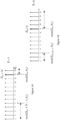
- the CDD basis subset indicator is represented by two values D and D in , where D defines the number of elements of the CDD basis subset, and D in represents the first index of the selected D delay vectors [ d mod ( D in , N 3) , d mod ( D in+1 , N 3) , ..., d mod ( D in+ D -1, N 3) ] from the second codebook.
- CDD basis subset configured by D and D in are shown in Figures 1A and 1B .
- the LDD subset indicator is given by a D -sized bitmap and each bit in the bitmap is associated with a delay vector from the CDD basis subset. A "1" may indicate that the associated delay vector is selected from the CDD basis subset, and a "0" may indicate that the associated delay vector is not selected from the CDD basis subset.
- the LDD subset indicator is given by a ⁇ log 2 D ⁇ D l ⁇ bit indicator.
- the UE for the indication of the payload size of the CDD basis subset indicator in the CSI report part 2, the UE is configured to report the parameter D in CSI report part 1. Furthermore, the UE is configured to report (if available) the parameter D in in CSI part 2.
- the UE for reducing the feedback overhead of the CSI report part 1, the UE is configured with the parameter D by the gNB (and hence not reported in CSI part 1), or the parameter D is a priori known at the UE (and hence not reported in CSI part 1).
- the UE for reducing the feedback overhead of the CSI report part 1, is configured with the parameter(s) D r by the gNB for each possible rank RI of the CSI matrix (and hence not to report the parameter D r in CSI part 1), or the parameter(s) D r are e.g. a priori known at the UE (and hence not reported).
- the UE for reducing the feedback overhead of the CSI report part 1, the UE is configured with the parameter(s) D in,r by the gNB for each possible rank RI of the CSI matrix (and hence not to report the parameter D in,r in CSI part 2), or the parameter(s) D in,r are a priori known at the UE (and hence not reported).
- D ⁇ in , r N 3 ⁇ ⁇ N 3 ′ 2 ⁇ + q , where q ⁇ ⁇ 1,2,.. ⁇ is an integer.
- the UE for reducing the feedback overhead of the CSI report (part 1 and part 2), is configured to receive the CDD basis subset indicator from the gNB, and not to report the CDD basis subset indicator in CSI part 2.
- the CDD basis subset indicator configured by the gNB may be rank-specific, and the gNB configures for each rank RI ⁇ ⁇ 1,2,3,4 ⁇ of the CSI matrix a CDD basis subset indicator.
- the CDD basis subset indicator configured by the gNB is given by a N 3 -sized bitmap, where the bitmap contains D 1's and each bit in the bitmap is associated with a delay vector from the second codebook.
- the CDD basis subset indicator is configured by a ⁇ log 2 N 3 D ⁇ ⁇ bit indicator, where the parameter D indicates the total number of selected delay vectors by the UE across all layers and is configured by the gNB.
- the UE for reducing the feedback overhead of the CSI report (part 1 and part 2), is configured to select the delay vectors for each layer from an a-priori known CDD basis subset indicator (e.g. known by 3GPP standard specification), and not to report the CDD basis subset indicator in CSI part 2.
- an a-priori known CDD basis subset indicator e.g. known by 3GPP standard specification
- the UE for reducing the feedback overhead of the CSI report (part 2), is configured to select the CDD basis subset indicator from a-priori known multiple CDD basis subsets of different sizes and to indicate in the CSI part 1 the size of the selected CDD basis subset.
- the CDD basis subset indicator sets are either higher layer configured or known at the UE (defined by specification).
- the UE for reducing the feedback overhead of the CSI report (part 1 and part 2), is configured to select the CDD basis subset indicator from a-priori known N equal-sized CDD basis subset indicator set(s), and to indicate in the CSI report part 2 the selected CDD basis subset and in the CSI part 1 the size of the selected CDD basis subset.
- the selected CDD basis subset indicator in CSI part 2 may be represented by a ⁇ log 2 N ⁇ bit indicator.
- the UE is configured to perform a N 3 -modulo shift operation on all delay indices of the vectors in the selected DD basis subset of a layer with respect to the delay index associated with the strongest coefficient indicator of the layer. Note that this shift operation has no impact on the performance of the precoder defined by the CSI matrix and the shifted DD basis subset. After this shift operation is applied, the delay index associated with the strongest coefficient is always associated with a known delay index, for example, the first delay index.
- the first delay index does not need to be reported and the DD basis subset indicator for the I-th layer is given by ( N 3 - 1) -sized bitmap, a ⁇ log 2 N 3 D l ⁇ 1 ⁇ bit indicator, or a ⁇ log 2 N 3 ⁇ 1 D l ⁇ 1 ⁇ bit indicator.
- the strongest coefficient indicator may then be represented by a ⁇ log 2 2 U l ⁇ bit indicator to indicate the row of the bitmap associated with the strongest coefficient.
- the UE is configured to perform a D -modulo shift operation on all delay indices of the vectors in the selected LDD basis subset with respect to the delay index associated with the strongest coefficient of the layer. Note that, similar to above, this shift operation has no impact on the performance of the precoder defined by the CSI matrix and the shifted LDD basis subset(s). After this shift operation is applied, the delay index associated with the strongest coefficient is always associated with the first delay index.
- the LDD basis subset indicator for the I-th Layer is given by ( D - 1)-sized bitmap, or a ⁇ log 2 D ⁇ D l ⁇ 1 ⁇ bit indicator, or a ⁇ log 2 D ⁇ ⁇ 1 D l ⁇ 1 ⁇ bit indicator.
- the CDD basis subset indicator may be represented by a ⁇ log 2 N 3 D ⁇ ⁇ 1 ⁇ bit indicator, or a ⁇ log 2 N 3 ⁇ 1 D ⁇ ⁇ 1 ⁇ bit indicator.
- the UE may report a value D ( l ) ' ( ⁇ D ( l ) ) in UCI part 1 indicating that the associated bitmap of the I-th layer contains only D ( l ) ' columns, instead of D ( l ) columns.
- the part of the bitmap containing only zeros is dropped from UCI part 2, In this way, the size of the bitmap is reduced from 2 U ( l ) ⁇ D ( l ) to 2 U ( l ) ⁇ D ( l ) ' and a feedback overhead saving is achieved.
- the value D ( l ) ' may be indicated in UCI part 1.
- D ( l ) ' may be indicated by the UE by a 1-bit indicator for all layers.
- the selected D ( l ) ' may be indicated by the UE by unused code-points of other UCI 1 parameters.
- 46 code-points are un-used and can be used for the indication of the selected value of D ( l ) '. Different examples are provided in the following.
- the UE may be configured to report a FD basis sufficiency indicator in the CSI report, the FD basis sufficiency indicator indicates whether the configuration of the values K (or K 1 or K 2 or K ( l ) ) or D ( l ) or ( D ( l , r ) ) or N 3 is sufficient to calculate the CSI matrix.
- the calculation of the CSI matrix is influenced by aliasing. Also, when the configured values of K (or K 1 or K 2 or K ( l ) ) or D ( l ) or ( D ( l , r ) ) may be too small, the UE may not be able to calculate the CSI matrix.
- the UE may be configured to report the basis sufficiency indicator explicitly in UCI part 1.
- the UE may be configured to explicitly indicate the basis sufficiency indicator using a 1-bit indicator in UCI part 1.
- a '1' of the bit indicator may indicate that the configured values K (or K 1 or K 2 or K ( l ) ) and/or D ( l ) or ( D ( l , r ) ) are sufficient, and a '0' may indicate that the values K (or K 1 or K 2 or K ( l ) ) and/or D ( l ) or ( D ( l,r ) ) are not sufficient.
- the UE may be configured to implicitly indicate the basis sufficiency indication by reporting a zero for the NNZCC in UCI part 1.
- the UE may be configured to implicitly indicate the basis sufficiency indication by reporting a value of two for the NNZCC in UCI part 1.
- the UE when the UE may be configured to indicate via the basis sufficiency indicator in UCI part 1 that if one of the values of K (or K 1 or K 2 or K ( l ) ) and/or D ( l ) or ( D ( l , r ) ) is not sufficient, the UE is configured to drop or partly drop the UCI part 2.
- the UE may be configured to fully drop UCI part 2.
- the UE may be configured to only report the selected SD basis subsets in UCI part 2.
- the UE may be configured to report a selected single SD basis vector along with the selected two non-zero combining coefficients per layer.
- the UE may be configured to report a selected single SD basis vector along with the selected two non-zero combining coefficients only for the first layer.
- the UE may be configured by the gNB with larger values of K (or K 1 or K 2 or K ( l ) ) and/or D ( l ) or ( D ( l , r ) ) or N 3 for future CSI reporting.
- the UE is configured to determine a layer-specific space domain (LSD) basis subset of the selected beam vectors and to indicate the beam vectors in the CSI report (part 2).
- the LSD basis subset indicator is given by a ⁇ log 2 N 1 N 2 U l ⁇ bit indicator for the I-th layer.
- the LSD basis subset indicator ⁇ log 2 N 1 N 2 U ⁇ is identical across all layers and reported once.
- the method performed by the UE comprises:
- the method comprises receiving a configuration from the gNB, said configuration comprising a CSI report configuration including at least one higher-layer parameters, D ( l ) , representing a number of delays per layer, used for the configuration of the precoder matrix or CSI matrix.
- the method further comprises receiving a configuration from the gNB, which configuration includes a single parameter D (0) for a first layer, and deriving the parameter(s) D ( l ) , l > 0 for the remaining layers.
- the configuration of delays is dependent on the Rank Indicator (RI) of the precoder matrix or the CSI matrix.
- the method comprises receiving a configuration from the gNB, said configuration comprising a CSI report configuration including at least one higher-layer parameters, U ( l ) , representing the number of spatial beams for the I-th layer, used for the configuration of the precoder matrix or the CSI matrix.
- the higher layer parameter U is a UE capability; and the method comprises indicating the supported value range for the parameter U to the gNB.
- the method may further comprise using a two-step approach to reduce the overall overhead for reporting the bitmaps of all layers, wherein in a first step, the UE determining determine a joint bitmap of size U g ⁇ D g by the union of individual bitmaps across the layers, and reporting to the gNB the number of '1's in the joint bitmap, and wherein in a second step, reporting to the gNB an indication of the indices of the selected non-zero combining coefficients associated with the joint bitmap.
- the method may further comprise reporting in an UCI (Uplink Control Information) part 2, an indication of selected Spatial Domain, SD, and/or Frequency Domain, FD, basis vectors associated with the joint bitmap.
- UCI Uplink Control Information
- the method may further comprise determining per layer an effective bitmap of size U e l ⁇ D e l , where U e l ⁇ 2 U l and D e l ⁇ D l , , wherein the effective bitmaps are reported in CSI part 2 and wherein each effective bitmap contains only non-zero rows and/or non-zero columns, and indicating in the CSI part 2, an indication of the selected SD basis vectors associated with the effective bitmap per layer and/or an indication of the selected FD basis vectors associated with the effective bitmap per layer.
- the method may further comprise indicating the sizes of the effective bitmaps for all layers in UCI part 1.
- the method further comprises determining a Common Delay Domain (CDD) basis subset of selected delay vectors across all layers, and indicating the delay vectors of the CDD basis subset by a CDD basis subset indicator in the CSI report.
- CDD Common Delay Domain
- the method further comprises indicating the selected delay vectors from the CDD basis subset for each layer by a layer-specific delay domain basis, LDD, subset indicator in the CSI report.
- the method may further comprise performing a N 3 -modulo shift operation on all delay indices of the vectors in a selected Delay Domain (DD) basis subset of a layer with respect to a delay index associated with the strongest coefficient indicator of the layer.
- DD Delay Domain
- the method performed by the UE further comprises selecting and reporting a parameter D in representing a first index of the delay vector in the CDD basis subset, such that the first delay vector associated with index 0 is included in the CDD subset.
- the UE is configured to report the parameter D in using a ⁇ log 2 N 3 ⁇ -bit indicator.
- the value range of the parameter n is reduced from D to d' values, and d' is either higher-layer configured or a priori known or determined by the UE for given parameters N 3 and/or D , and wherein the value n is reported by the UE using a ⁇ log 2 d ′ ⁇ -bit indicator.
- the value range of the parameter q is either higher-layer configured, or fixed and a priori known to the UE or determined by the UE based on the configured N 3 and D values.
- each of the d' codepoints is represented by a ⁇ log 2 d ′ ⁇ -bit indicator, where the first codepoint is represented by ⁇ log 2 d ′ ⁇ -zeros and associated with the smallest integer value in the value range of q, and wherein the remaining values in the pre-defined set of d' values are mapped to codepoints in an increasing order.
- the zero value is mapped to the first codepoint, represented by ⁇ log 2 d ′ ⁇ - zeros.
- the reporting of the parameter D in may be dependent on the transmission rank, and for a low rank transmission, the parameter D in may be fixed, hence not reported.
- the value of D in is reported when the transmission rank is larger than a threshold value.
- the value of D in is reported when the configured value of D is smaller than a threshold value.
- the parameter D defining the CDD basis subset size, depends on the transmission rank, wherein the CDD basis subset size increases with increasing transmission rank.
- the size of the CDD basis subset D depends on the configured number of Spatial Domain (SD) basis vectors, where the value of D configured for larger number of SD basis vectors is smaller than the value of D configured for smaller number of SD basis vectors.
- SD Spatial Domain
- the CDD basis subset is defined by two values D and D in , where D denotes the number of elements in the CDD basis subset, and D in represents the first index of the selected D delay vectors.
- the common delay domain, CDD, basis subset indicator indicating a common continuous subset of delay vectors across all layers is defined by the parameter D in representing the first index of the delay vector of the CDD basis subset and the parameter D representing the number of delay vectors of the CDD basis subset.
- the UE selects the starting index of the CDD basis subset D in from the N 3 -sized set [0,1, ..., N 3 - 1].
- the UE is configured to report the selected value of D in using a ⁇ log 2 N 3 ⁇ -bit indicator.
- the UE is configured to select and report the parameter D in such that the FD basis vector associated with the SCI (which is not necessarily the first FD basis vector) is included in the CDD basis subset.
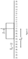
- the value range of D in is reduced from N 3 to D values and is given by a function of N 3 and D , and is defined by equation (1): mod d SCI ⁇ D ⁇ + 1 + n , N 3 , n ⁇ 0 , D ⁇ ⁇ 1 where d SCI is the index of the FD basis vector associated with the SCI.
- the FD basis vector associated with the strongest combining coefficient per layer is cyclically shifted to the FD basis vector index 0.
- the first FD basis vector (corresponding to index 0) is associated with the strongest combining coefficient. Therefore, according to an embodiment, the parameter D in is selected by the UE in a way that the CDD basis subset contains the first FD basis vector which is associated with index 0, see Figure 3 .
- the FD basis vector 0 is included when D in is given by one of the values from the set [19,20,21,22,23,24,25,0].
- Table 1 shows the corresponding value range of D in for different values of N 3 and D . It can be observed that the value range of D in is dependent on N 3 and D .
- Table 1 Values of D in for different combinations of N 3 and D N 3 D
- Values of D in 26 6 [0, 21, 22, 23, 24, 25] 8 [0, 19, 20, 21, 22, 23, 24, 25] 10 [0, 17,18,19, 20, 21, 22, 23, 24, 25] 12 [0, 15, 16, 17, 18, 19, 20, 21, 22, 23, 24, 25] 38 8 [0, 33, 34, 35, 36, 37] 10 [0, 29, 30, 31, 32, 33, 34, 35, 36, 37] 13 [0, 26, 27, 28, 29, 30, 31, 32, 33, 34, 35, 36, 37] 16 [0,23, 24, 25, 26, 27, 28, 29, 30, 31, 32, 33, 34, 35, 36, 37]
- the UE when the UE is configured to perform a cyclic shift operation on the selected combining coefficients and the selected FD basis vectors per layer with respect to the FD basis vector that is associated with the SCI, the UE is configured to select and report the parameter D in such that the first FD basis vector (associated with index 0) is included in the CDD basis subset.
- the value range of D in is reduced from N 3 to D values and is given by a function of N 3 and D , and is defined by equation (2): mod N 3 ⁇ D ⁇ + 1 + n , N 3 , n ⁇ 0 , D ⁇ ⁇ 1
- the UE may be configured to report D in using a ⁇ log 2 D ⁇ ⁇ -bit indicator.
- the selected value of n is reported using a ⁇ log 2 D ⁇ ⁇ -bit indicator.
- the size of the bit indicator for reporting the value of D in depends on the CDD subset size D .
- the feedback overhead for reporting D in increases with increasing values of D .
- the value range of D in may be limited to d' values, such that the corresponding bit indicator for D in has a fixed size.
- the value of the starting index of the CDD subset D in is reported using a ⁇ log 2 d ′ ⁇ -bit indicator.
- the value range of D in is defined by d' values, where the parameter d' is either higher-layer configured or a priori known or determined by the UE for given parameters N 3 and/or D .
- the selected D in values are spread over the entire allowable range of D in
- the indices that lie in the center of the allowable range of D in are selected with higher probability than the remaining indices.
- the value range of D in may therefore be defined by those values that are selected with high probability. It can also be observed that for the values of D in that are selected with high probability, the CDD basis subset is centered with FD index 0 that is associated with the strongest coefficient.
- the value range of the parameter n is reduced from D to d' values, and d' is either higher-layer configured or a priori known or determined by the UE for given parameters N 3 and/or D , and wherein the value n is reported by the UE using a ⁇ log 2 d ′ ⁇ -bit indicator.
- the parameter d' is either higher-layer configured or a priori known or determined by the UE for given parameters N 3 and/or D .
- d' 2 d" , where d " ⁇ Z + .
- d' is an even numbered value.
- d' D .
- the value range of the parameter q may be higher layer configured, or fixed and a priori known to the UE or determined by the UE based on the configured N 3 and D values.
- the UE may be configured to report the selected value of q to the gNB, instead of reporting the parameter D in .
- the gNB determines the value of D in from the reported value of q based on equation (2).
- Each value of q selected from the pre-defined set of d' values is mapped to a codepoint, represented by a value of a ⁇ log 2 d ′ ⁇ -bit indicator.
- a specific mapping rule is required. In the following, two mapping rules are proposed.
- each of the d' codepoints is represented by a ⁇ log 2 d ′ ⁇ -bit indicator, where the first codepoint is represented by ⁇ log 2 d ′ ⁇ -zeros and associated with the smallest integer value in the value range of q.
- the remaining values in the pre-defined set of d' values are mapped to codepoints in an increasing order, as shown in Table 2, option A.
- the zero value is mapped to the first codepoint, represented by ⁇ log 2 d ′ ⁇ -zeros.
- the remaining values in the pre-defined set of d' values are mapped to codepoints in an increasing order, as shown in Table 2 below, option B.
- Option A q Codepoint q Codepoint -1 00 0 00 0 01 1 01 1 10 2 10 2 11 -1 11
- the UE in order to save feedback overhead for the reporting of the parameter D in , the UE may be configured to report the parameter q based on equation (3) or n based on equation (1) or (2), that determines the parameter D in .
- the reporting of either the parameter n or q may depend on the parameter D .
- the value of n may be reported when D is less than a threshold value, and otherwise the value of q may be reported.
- the UE may report the selected value of n , otherwise, it reports the selected value of q.
- the delay spread of the corresponding beam-formed channel impulse response associated with a layer of the precoder matrix becomes larger, thus requiring a larger CDD basis subset size of the precoder matrix for covering the delay spread of the corresponding beam-formed channel impulse response. Therefore, the size of the CDD basis subset D depends on the transmission rank, and the value of D may increase with increasing transmission rank. Moreover, for a low rank transmission, the selected value of D in from the pre-defined value range of q, given by equation (2), does not significantly affect the performance. Therefore, for low-rank transmission, D in can be fixed.
- the reporting of the parameter D in may be dependent on the transmission rank.
- the parameter D in may be fixed (hence not reported).
- R' 1.
- R' ⁇ ⁇ 1,2 ⁇ .
- the reporting of the parameter D in may be performed when the transmission rank is larger than a threshold.
- the reporting of the parameter D in may depend on the configured parameter D .
- the value of D in (or the associated parameter n or q) may be reported when the configured value of D is smaller than a threshold value, otherwise the value of D in (or the associated parameter n or q) is fixed (and hence not reported).
- the delay spread of the corresponding beam-formed channel impulse response associated with a layer of the precoder matrix becomes larger, thus requiring a larger CDD basis subset size of the precoder matrix for covering the delay spread of the corresponding beam-formed channel impulse response. Therefore, according to an embodiment, the size of the CDD basis subset D depends on the transmission rank, and the value of D may increase with increasing transmission rank.
- the parameter D defining the CDD basis subset size, may depend on the transmission rank.
- the size of the CDD basis subset configured for a rank- R' transmission may always be equal or smaller than the size of the CDD basis subset configured for a rank- R" transmission, where R' ⁇ R".
- D 10.
- the delay impulse response associated with an SD beam is associated with only one or few channel cluster(s) of the radio channel, where each channel cluster is characterized by a single mean delay.
- the configured CDD basis subset D depends on the configured number of SD beams U or U ( l ) .
- the delay spread of the corresponding beam-formed channel impulse response becomes larger, thus requiring a larger CDD basis subset for covering the delays of the precoder matrix.
- the size of the CDD basis subset D depends on the configured number of SD basis vectors.
- the configured CDD basis subset size D increases with increasing values of U or U ( l ) .
- the value of D configured for larger number of SD basis vectors may be smaller than the value of D configured for smaller number of SD basis vectors.
- the SCI may be configured to be rank-dependent. For example, for a rank-1 transmission, the SCI is given by a ⁇ log 2 K NZ ⁇ -bit indicator, and for a higher rank (RI>1) transmission, the SCI is given by a ⁇ log 2 2 U ⁇ -bit indicator.
- the UE is configured to use CDD basis subset-based reporting when the configured number of CQI subbands N SB is greater than a threshold value. For example, N SB > 13.
- the UE is configured to use the CDD basis subset-based reporting when the total number of subbands N 3 is greater than a threshold value. For example, N 3 > 19.
- the UE When the UE is enforced to perform a cyclic shift operation on the selected combining coefficients and the selected DD basis vectors per layer with respect to the FD basis vector associated with the SCI, e.g., the SCI is given by a ⁇ log 2 2 U ⁇ - bit indicator, a reporting of a '1' in the bitmap used to indicate the position of the strongest coefficient is redundant. Therefore, the size of the bitmap reported by the UE can be reduced by a single bit per layer.
- the complete bitmap of size 2 U ( l ) D ( l ) is required to indicate the SD basis vector index and FD basis vector index of the SCI.
- the size of the bitmap associated with each layer can be reduced from to 2 U ( l ) D ( l ) to 2 U ( l ) D ( l ) - 1 bits.
- the size of the bitmap may be rank-dependent as well.
- the SCI is given by a ⁇ log 2 K NZ ⁇ -bit indicator, and the associated bitmap has a size of 2 U ( l ) D ( l )
- the SCI is given by a ⁇ log 2 2 U ⁇ -bit indicator and the size of the bitmap per layer is given by 2 U ( l ) D ( l ) - 1.
- the indicator associated with the reporting of the selected NNZCC across all layers in CSI part 1 is given by a ⁇ log 2 g ⁇ -bit indicator.
- the particular value of g may depend on the transmission rank.
- the ⁇ log 2 g ⁇ -bit indicator indicating the number of non-zero combining coefficients for the CSI matrix of the CSI report in CSI part 1 is rank-dependent.
- K 0 denotes the maximum NNZCC per layer, which is higher layer configured to the UE by the gNB.
- the amplitude and phase information associated with the strongest coefficient of each layer is normalized to 1 and hence not reported. Therefore, the UE may indicate only the NNZCC across all layers for which the amplitude and phase information is reported in CSI part 2.
- the selected D ( l ) ' may be indicated by the UE by unused code-points of other UCI 1 parameters.
- the unused code-points used for the indication of the number of non-zero combining coefficients may be used to report in addition the 1-bit indicator for D ( l ) ' for all layers.
- the 44+RI un-used code-points are used for the indication of the selected value of D ( l ) '.
- UE 300 comprises a processor 310 or processing circuit or a processing module or a processor or means 310; a receiver circuit or receiver module 340; a transmitter circuit or transmitter module 350; a memory module 320 a transceiver circuit or transceiver module 330 which may include the transmitter circuit 350 and the receiver circuit 340.
- the UE 300 further comprises an antenna system 360 which includes antenna circuitry for transmitting and receiving signals to/from at least the UE.
- the antenna system employs beamforming as previously described.
- the UE 300 may operate in any radio access technology including 2G, 3G, 4G or LTE, LTE-A, 5G, WLAN, and WiMax etc. that support beamforming technology.
- the processing module/circuit 310 includes a processor, microprocessor, an application specific integrated circuit (ASIC), field programmable gate array (FPGA), or the like, and may be referred to as the "processor 310."
- the processor 310 controls the operation of the UE 300 and its components.
- Memory (circuit or module) 320 includes a random access memory (RAM), a read only memory (ROM), and/or another type of memory to store data and instructions that may be used by processor 310.
- RAM random access memory
- ROM read only memory
- the UE 300 in one or more embodiments includes fixed or programmed circuitry that is configured to carry out the operations in any of the embodiments disclosed herein.
- the UE 300 includes a microprocessor, microcontroller, DSP, ASIC, FPGA, or other processing circuitry that is configured to execute computer program instructions from a computer program stored in a non-transitory computer-readable medium that is in, or is accessible to the processing circuitry.
- non-transitory does not necessarily mean permanent or unchanging storage, and may include storage in working or volatile memory, but the term does connote storage of at least some persistence.
- the execution of the program instructions specially adapts or configures the processing circuitry to carry out the operations disclosed herein including any one of method claims 1-11. Further, it will be appreciated that the UE 300 may comprise additional components not shown in Figure 5 .
- the method comprises: transmitting to a UE a radio signal via a MIMO channel, wherein the radio signal contains at least one DL, reference signal according to a DL reference signal configuration, for enabling the UE to estimate said MIMO channel based on said received at least one DL reference signal for configured subbands and calculate a precoder matrix or a CSI matrix for a number of antenna ports of the gNB and configured subbands; the precoder matrix being based on a first codebook and on a second codebook and a set of combining coefficients for complex scaling/combining one or more of vectors selected from the first codebook and the second codebook; where, the first codebook contains one or more transmit-side spatial beam components of the precoder matrix, the second codebook contains one or more delay components of the precoder matrix, and receiving, from the UE, a CSI feedback report and/or a PMI and/or a PMI/RI, used to
- the gNB comprises a processor or processing circuit or a processing module or a processor or means; a receiver circuit or receiver module; a transmitter circuit or transmitter module; a memory module a transceiver circuit or transceiver module which may include the transmitter circuit and the receiver circuit.
- the gNB further comprises an antenna system which includes antenna circuitry for transmitting and receiving/transmitting signals to/from at least the UE.
- the antenna system employs beamforming as previously described.
- the gNB may operate in any radio access technology including 2G, 3G, 4G or LTE, LTE-A, 5G, WLAN, and WiMax etc. that support beamforming technology.
- the processing module/circuit includes a processor, microprocessor, an application specific integrated circuit (ASIC), field programmable gate array (FPGA), or the like, and may be referred to as the "processor.”
- the processor controls the operation of the gNB and its components.
- Memory includes a random access memory (RAM), a read only memory (ROM), and/or another type of memory to store data and instructions that may be used by processor.
- RAM random access memory
- ROM read only memory
- the gNB in one or more embodiments includes fixed or programmed circuitry that is configured to carry out the operations in any of the embodiments disclosed herein.
- the gNB includes a microprocessor, microcontroller, DSP, ASIC, FPGA, or other processing circuitry that is configured to execute computer program instructions from a computer program stored in a non-transitory computer-readable medium that is in, or is accessible to the processing circuitry.
- non-transitory does not necessarily mean permanent or unchanging storage, and may include storage in working or volatile memory, but the term does connote storage of at least some persistence.
- the execution of the program instructions specially adapts or configures the processing circuitry to carry out the operations disclosed in this disclosure. Further, it will be appreciated that the gNB may comprise additional components.
- the word "comprise” or “comprising” has been used in a non-limiting sense, i.e. meaning “consist at least of”. Although specific terms may be employed herein, they are used in a generic and descriptive sense only and not for purposes of limitation.
- the embodiments herein may be applied in any wireless systems including GSM, 3G or WCDMA, LTE or 4G, LTE-A (or LTE-Advanced), 5G, WiMAX, WiFi, satellite communications, TV broadcasting etc. that may employ beamforming technology.
Landscapes
- Engineering & Computer Science (AREA)
- Computer Networks & Wireless Communication (AREA)
- Signal Processing (AREA)
- Physics & Mathematics (AREA)
- Mathematical Physics (AREA)
- Power Engineering (AREA)
- Radio Transmission System (AREA)
- Mobile Radio Communication Systems (AREA)
- Arrangements For Transmission Of Measured Signals (AREA)
- Circuits Of Receivers In General (AREA)
- Alarm Systems (AREA)
Claims (12)
- Verfahren, das durch ein Benutzergerät (UE) durchgeführt wird, wobei das Verfahren Folgendes umfasst:- Empfangen (201) von einem Netzwerkknoten (gNB) eines Funksignals über einen Multiple Input Multiple Output (MIMO)-Kanal, wobei das Funksignal mindestens ein DownLink-, DL-Referenzsignal gemäß einer DL-Referenzsignalkonfiguration enthält;- Schätzen (202) des MIMO-Kanals basierend auf dem empfangenen mindestens einen DL-Referenzsignal für konfigurierte Teilbänder;- Berechnung (203) einer Vorcodierermatrix oder einer Kanalzustandsinformationsmatrix (CSI-Matrix) für eine Anzahl von Antennenanschlüssen des gNB und konfigurierten Teilbändern, N3 ; wobei die Vorcodierermatrix auf einem ersten Codebuch und einem zweiten Codebuch und einem Satz von Kombinationskoeffizienten für die komplexe Skalierung/Kombination eines oder mehrerer Vektoren basiert, die aus dem ersten Codebuch und dem zweiten Codebuch ausgewählt wurden;
wo,- das erste Codebuch eine oder mehrere sendeseitige räumliche Strahlkomponenten der Vorcodierermatrix oder CSI-Matrix enthält,- das zweite Codebuch eine oder mehrere Verzögerungskomponenten der Vorcodierermatrix oder CSI-Matrix enthält,- Bestimmen einer gemeinsamen Verzögerungsdomäne (CDD), einer Basis von Untergruppen der ausgewählten Vektoren, die den Verzögerungskomponenten über alle Schichten der Vorcodierermatrix oder CSI-Matrix zugeordnet sind, wobei die Basis von Untergruppen CDD durch einen ParameterD definiert ist, der die Anzahl der Elemente der Basis von Untergruppen CDD darstellt und einen ParameterD in , der den ersten Index derD Verzögerungsvektoren aus dem zweiten Codebuch darstellt, wobei der Wertebereich des ParametersD in von N3 aufD Werte reduziert wird; und- Berichten (204) eines CSI-Rückmeldungsberichts und/oder eines Vorcodierermatrix-Indikators (PMI und/oder PMI/Rank-Indikators, PMI/RI) an den gNB, der verwendet werden, um die Vorcodiermatrix oder die CSI-Matrix für die konfigurierten Antennenanschlüsse und die konfigurierten Teilbänder anzuzeigen; wobei die ausgewählten Vektoren aus der CDD auf Basis von Untergruppen in der Berichterstattung für jede Schicht durch eine schichtspezifische Verzögerungsdomäne (LDD) auf Basis eines Untergruppenanzeigers angezeigt werden; und der ParameterD in an den gNB berichtet wird. - Verfahren nach Anspruch 1, das das Empfangen einer Konfiguration vom gNB umfasst, wobei die Konfiguration eine CSI-Berichtskonfiguration umfasst, die mindestens einen Parameter einer höheren Schicht enthält, D (l), der eine Anzahl von Verzögerungen pro Schicht darstellt, die für die Konfiguration der Vorcodierermatrix verwendet werden oder CSI-Matrix.
- Verfahren nach Anspruch 2, wobei die Anzahl der Verzögerungen D (l) schichtunabhängig und für alle Schichten identisch ist, so dass D (l) = D, und das UE mit nur einem einzigen Parameter D für die Konfiguration der Vorcodierermatrix oder CSI-Matrix konfiguriert wird.
- Verfahren nach Anspruch 1, umfassend das Durchführen einer N 3-Modulo-Verschiebungsoperation an allen Verzögerungsindizes, die den ausgewählten Verzögerungsvektoren zugeordnet sind, die durch den LDD auf Basis des Untergruppenanzeigers angezeigt werden, und an allen Nicht-Null-Kombinationskoeffizienten einer Schicht in Bezug auf eine Verzögerung Index, der dem stärksten Koeffizientenindikator (SCI) der Schicht zugeordnet ist.
- Verfahren nach Anspruch 1 oder Anspruch 4, wobei der Parameter
D in so ausgewählt wird, dass der erste Verzögerungsvektor, der dem Index 0 zugeordnet ist, in der Basis von Untergruppen CDD enthalten ist. - Verfahren nach Anspruch 1 oder Anspruch 4 oder Anspruch 5, wobei der Wertebereich des Parameters
D in definiert ist durch:D in = mod(dSCI -D + 1 + n, N 3), n e [0,15- 1], wobei dSCI der Index des Frequenzbereichs (FD) ist, der dem SCI zugeordnet ist, und das UE so konfiguriert ist, dass esD in unter Verwendung eines
- Verfahren nach Anspruch 1 oder Anspruch 4 oder Anspruch 5, wobei der Wertebereich des Parameters
D in definiert ist durch:D in = mod(N3 -D + 1 + n,N3 ),n ∈ [0,D - 1] , und das UE ist so konfiguriert, dass esD in mithilfe eines
- Verfahren nach einem der vorhergehenden Ansprüche, wobei der Parameter
D , der die Größe der Basis von Untergruppen CDD definiert, vom Übertragungsrang abhängt. - Verfahren nach Anspruch 4, wobei der SCI so konfiguriert ist, dass er rangabhängig ist; wobei für eine RI=1-Übertragung der SCI durch einen


- Benutzergerät, UE, (300) das einen Prozessor (310) und einen Speicher (320) umfasst, wobei der Speicher (320) Anweisungen enthält, die durch den Prozessor (310) ausführbar sind, wodurch das UE (300) betreibbar ist, um das Verfahren nach einem der Ansprüche 1-9 durchzuführen.
- Verfahren, das durch einen Netzknoten (gNB) durchgeführt wird, wobei das Verfahren Folgendes umfasst:- Senden eines Funksignals über einen Mehrfacheingangs-Mehrfachausgangskanal (MIMO-Kanal) an ein Benutzergerät (UE), wobei das Funksignal mindestens ein DownLink-(DL)-Referenzsignal gemäß einer DL-Referenzsignalkonfiguration enthält; um dem UE Folgendes zu ermöglichen:- Schätzung des MIMO-Kanals auf der Grundlage des empfangenen mindestens einen DL-Referenzsignals für konfigurierte Teilbänder;- Berechnung (203) einer Vorcodierermatrix oder einer Kanalzustandsinformationsmatrix (CSI-Matrix) für eine Anzahl von Antennenanschlüssen des gNB und konfigurierten Teilbändern, N3 ; wobei die Vorcodierermatrix auf einem ersten Codebuch und einem zweiten Codebuch und einem Satz von Kombinationskoeffizienten für die komplexe Skalierung/Kombination eines oder mehrerer Vektoren basiert, die aus dem ersten Codebuch und dem zweiten Codebuch ausgewählt wurden;
wo,- das erste Codebuch eine oder mehrere sendeseitige räumliche Strahlkomponenten der Vorcodierermatrix oder CSI-Matrix enthält,- das zweite Codebuch eine oder mehrere Verzögerungskomponenten der Vorcodierermatrix oder CSI-Matrix enthält;- Bestimmung einer gemeinsamen Verzögerungsdomäne (CDD), einer Basis von Untergruppen der ausgewählten Vektoren, die den Verzögerungskomponenten über alle Schichten der Vorcodierermatrix oder CSI-Matrix zugeordnet sind, wobei die Basis von Untergruppen CDD durch einen ParameterD definiert ist, der die Anzahl der Elemente der Basis der Untergruppen CDD darstellt und einen ParameterD in , der den ersten Index derD Verzögerungsvektoren aus dem zweiten Codebuch darstellt, wobei der Wertebereich des ParametersD in von N3 aufD Werte reduziert wird; und- Empfangen eines CSI-Rückmeldungsberichts und/oder eines Vorcodierermatrix-Indikators (PMI und/oder PMI/Rank-Indikator, PMI/RI) vom UE, der verwendet wird, um die Vorcodierermatrix oder die CSI-Matrix für die konfigurierten Antennenanschlüsse und die konfigurierten Teilbänder anzuzeigen; wobei die ausgewählten Vektoren aus der CDD auf Basis von Untergruppen in dem Bericht für jede Schicht durch eine schichtspezifische Verzögerungsdomäne (LDD) auf Basis eines Untergruppenanzeigers angezeigt werden; und der ParameterD in an den gNB berichtet wird. - Netzwerkknoten, der einen Prozessor und einen Speicher umfasst, wobei der Speicher Anweisungen enthält, die durch den Prozessor ausführbar sind, wodurch der Netzwerkknoten betreibbar ist, um den Gegenstand von Anspruch 11 durchzuführen.
Priority Applications (1)
| Application Number | Priority Date | Filing Date | Title |
|---|---|---|---|
| EP23179674.9A EP4236103A3 (de) | 2019-05-02 | 2020-04-14 | Verfahren und vorrichtung zur verbesserung auf basis von untergruppenanzeige für auf zwei codebüchern basierende csi-meldung |
Applications Claiming Priority (3)
| Application Number | Priority Date | Filing Date | Title |
|---|---|---|---|
| EP19172422.8A EP3734852A1 (de) | 2019-05-02 | 2019-05-02 | Verfahren und vorrichtungen zur csi-meldung in einem drahtloskommunikationssystem |
| EP19191235.1A EP3734853A1 (de) | 2019-05-02 | 2019-08-12 | Verfahren und vorrichtung zur verbesserung auf basis von untergruppenanzeige für auf zwei codebüchern basierende csi-meldung |
| PCT/EP2020/060397 WO2020221581A1 (en) | 2019-05-02 | 2020-04-14 | Methods and apparatuses for enhancement on basis subset indication for two-codebook based csi reporting |
Related Child Applications (1)
| Application Number | Title | Priority Date | Filing Date |
|---|---|---|---|
| EP23179674.9A Division EP4236103A3 (de) | 2019-05-02 | 2020-04-14 | Verfahren und vorrichtung zur verbesserung auf basis von untergruppenanzeige für auf zwei codebüchern basierende csi-meldung |
Publications (2)
| Publication Number | Publication Date |
|---|---|
| EP3963732A1 EP3963732A1 (de) | 2022-03-09 |
| EP3963732B1 true EP3963732B1 (de) | 2023-07-05 |
Family
ID=66397071
Family Applications (5)
| Application Number | Title | Priority Date | Filing Date |
|---|---|---|---|
| EP19172422.8A Withdrawn EP3734852A1 (de) | 2019-05-02 | 2019-05-02 | Verfahren und vorrichtungen zur csi-meldung in einem drahtloskommunikationssystem |
| EP19191235.1A Withdrawn EP3734853A1 (de) | 2019-05-02 | 2019-08-12 | Verfahren und vorrichtung zur verbesserung auf basis von untergruppenanzeige für auf zwei codebüchern basierende csi-meldung |
| EP20717210.7A Pending EP3963733A1 (de) | 2019-05-02 | 2020-04-14 | Verfahren und vorrichtungen zur csi-meldung in einem drahtloskommunikationssystem |
| EP23179674.9A Pending EP4236103A3 (de) | 2019-05-02 | 2020-04-14 | Verfahren und vorrichtung zur verbesserung auf basis von untergruppenanzeige für auf zwei codebüchern basierende csi-meldung |
| EP20717208.1A Active EP3963732B1 (de) | 2019-05-02 | 2020-04-14 | Verfahren und vorrichtung zur verbesserung auf basis von untergruppenanzeige für auf zwei codebüchern basierende csi-meldung |
Family Applications Before (4)
| Application Number | Title | Priority Date | Filing Date |
|---|---|---|---|
| EP19172422.8A Withdrawn EP3734852A1 (de) | 2019-05-02 | 2019-05-02 | Verfahren und vorrichtungen zur csi-meldung in einem drahtloskommunikationssystem |
| EP19191235.1A Withdrawn EP3734853A1 (de) | 2019-05-02 | 2019-08-12 | Verfahren und vorrichtung zur verbesserung auf basis von untergruppenanzeige für auf zwei codebüchern basierende csi-meldung |
| EP20717210.7A Pending EP3963733A1 (de) | 2019-05-02 | 2020-04-14 | Verfahren und vorrichtungen zur csi-meldung in einem drahtloskommunikationssystem |
| EP23179674.9A Pending EP4236103A3 (de) | 2019-05-02 | 2020-04-14 | Verfahren und vorrichtung zur verbesserung auf basis von untergruppenanzeige für auf zwei codebüchern basierende csi-meldung |
Country Status (7)
| Country | Link |
|---|---|
| US (3) | US20220224391A1 (de) |
| EP (5) | EP3734852A1 (de) |
| JP (2) | JP7398478B2 (de) |
| KR (2) | KR102568574B1 (de) |
| CN (2) | CN114128161B (de) |
| ES (1) | ES2952647T3 (de) |
| WO (2) | WO2020221581A1 (de) |
Families Citing this family (18)
| Publication number | Priority date | Publication date | Assignee | Title |
|---|---|---|---|---|
| US11949483B2 (en) * | 2021-02-01 | 2024-04-02 | Koninklijke Philips N.V. | Methods and apparatuses for codebook restriction for type-II feedback reporting and higher layer configuration and reporting for linear combination codebook in a wireless communications network |
| EP3949185A4 (de) * | 2019-04-04 | 2022-11-09 | Nokia Technologies Oy | Uplink-steuerinformationen |
| US11757855B2 (en) * | 2019-05-02 | 2023-09-12 | Electronics And Telecommunications Research Institute | Method and apparatus for communications using secret key in communication system |
| JP7431231B2 (ja) * | 2019-06-10 | 2024-02-14 | 株式会社Nttドコモ | 端末、無線通信方法及びシステム |
| CN114667758A (zh) * | 2019-11-29 | 2022-06-24 | 中兴通讯股份有限公司 | 用于压缩无线信道状态信息反馈的方法 |
| JP2023513522A (ja) * | 2020-02-07 | 2023-03-31 | 株式会社Nttドコモ | タイプiiチャネル状態情報(csi)用のサウンディング参照信号(srs)アシストsdビーム及びfdベクトル報告 |
| US12088378B2 (en) * | 2020-09-18 | 2024-09-10 | Qualcomm Incorporated | Low overhead and high accuracy channel state feedback using neural networks |
| US20220124537A1 (en) * | 2020-10-20 | 2022-04-21 | Samsung Electronics Co., Ltd. | Method and apparatus for csi reporting based on a port selection codebook |
| EP4002713A1 (de) * | 2020-11-23 | 2022-05-25 | Fraunhofer-Gesellschaft zur Förderung der angewandten Forschung e.V. | Csi-meldung auf basis eines linearen kombinations-codebuchs |
| CN114531183A (zh) * | 2020-11-23 | 2022-05-24 | 华为技术有限公司 | 信道矩阵的确定方法、装置及系统 |
| US20220190897A1 (en) * | 2020-12-14 | 2022-06-16 | Samsung Electronics Co., Ltd. | Codebook for distributed mimo transmission |
| US12047145B2 (en) * | 2021-02-03 | 2024-07-23 | Samsung Electronics Co., Ltd. | Method and apparatus for CSI reporting |
| US20240171229A1 (en) * | 2021-03-19 | 2024-05-23 | Fraunhofer-Gesellschaft zur Förderung der angewandten Forschung e.V. | Methods and Apparatuses with CSI Omission for Linear Combination Port-Selection Codebook |
| PL4092922T3 (pl) * | 2021-05-11 | 2024-03-18 | Nokia Technologies Oy | Informacje dotyczące kodowania wstępnego |
| WO2023184147A1 (en) * | 2022-03-29 | 2023-10-05 | Qualcomm Incorporated | Selection and quantization of time domain coefficients through an extended etype-ii codebook |
| WO2023231039A1 (en) * | 2022-06-03 | 2023-12-07 | Qualcomm Incorporated | Per-beam time-domain basis selection for channel state information codebook |
| WO2024050811A1 (en) * | 2022-09-09 | 2024-03-14 | Huawei Technologies Co., Ltd. | Systems and methods for supporting multi-layer transmission in a wireless network |
| WO2024152353A1 (en) * | 2023-01-20 | 2024-07-25 | Nec Corporation | Methods, devices and medium for communication |
Family Cites Families (12)
| Publication number | Priority date | Publication date | Assignee | Title |
|---|---|---|---|---|
| US7885354B2 (en) * | 2004-04-02 | 2011-02-08 | Rearden, Llc | System and method for enhancing near vertical incidence skywave (“NVIS”) communication using space-time coding |
| WO2009040775A2 (en) * | 2007-09-28 | 2009-04-02 | Nokia Corporation | User equipment-initiated precoding subset restriction for communication systems |
| JP5990815B2 (ja) * | 2011-11-07 | 2016-09-14 | シャープ株式会社 | 基地局、端末、通信システムおよび通信方法 |
| US9698881B2 (en) * | 2014-11-14 | 2017-07-04 | Telefonaktiebolaget Lm Ericsson (Publ) | Feedback channel transmission and detection in multi antenna wireless communication systems |
| US9680535B2 (en) | 2015-01-16 | 2017-06-13 | Samsung Electronics Co., Ltd. | Method and apparatus for reduced feedback FD-MIMO |
| US9935702B2 (en) * | 2015-03-04 | 2018-04-03 | Lg Electronics Inc. | Method and apparatus for feeding back channel state information for 3D MIMO in wireless communication system |
| US9967012B2 (en) * | 2015-05-06 | 2018-05-08 | Samsung Electronics Co., Ltd. | Method and apparatus for channel state information (CSI) reporting |
| WO2016183737A1 (en) * | 2015-05-15 | 2016-11-24 | Qualcomm Incorporated | Enhanced csi procedures for fd-mimo |
| KR102202038B1 (ko) * | 2015-07-23 | 2021-01-12 | 엘지전자 주식회사 | 다중 안테나 무선 통신 시스템에서 코드북 기반 신호 송수신 방법 및 이를 위한 장치 |
| EP3955473A1 (de) * | 2016-09-26 | 2022-02-16 | LG Electronics Inc. | Verfahren zum senden und empfangen von kanalstatusinformationen in einem drahtloskommunikationssystem und entsprechende vorrichtung |
| EP3635876A1 (de) * | 2017-06-06 | 2020-04-15 | Intel Corporation | Codebuch-subseteinschränkung für csi |
| EP3474459A1 (de) * | 2017-10-18 | 2019-04-24 | Fraunhofer-Gesellschaft zur Förderung der angewandten Forschung e.V. | Empfänger, sender, system und verfahren mit raumverzögerungsvorcodierung |
-
2019
- 2019-05-02 EP EP19172422.8A patent/EP3734852A1/de not_active Withdrawn
- 2019-08-12 EP EP19191235.1A patent/EP3734853A1/de not_active Withdrawn
-
2020
- 2020-04-14 KR KR1020217039712A patent/KR102568574B1/ko active IP Right Grant
- 2020-04-14 JP JP2021564881A patent/JP7398478B2/ja active Active
- 2020-04-14 WO PCT/EP2020/060397 patent/WO2020221581A1/en unknown
- 2020-04-14 ES ES20717208T patent/ES2952647T3/es active Active
- 2020-04-14 EP EP20717210.7A patent/EP3963733A1/de active Pending
- 2020-04-14 WO PCT/EP2020/060409 patent/WO2020221582A1/en unknown
- 2020-04-14 EP EP23179674.9A patent/EP4236103A3/de active Pending
- 2020-04-14 CN CN202080048725.1A patent/CN114128161B/zh active Active
- 2020-04-14 US US17/607,204 patent/US20220224391A1/en active Pending
- 2020-04-14 CN CN202080049048.5A patent/CN114128162B/zh active Active
- 2020-04-14 KR KR1020217039713A patent/KR20220003094A/ko not_active Application Discontinuation
- 2020-04-14 US US17/606,924 patent/US11901996B2/en active Active
- 2020-04-14 EP EP20717208.1A patent/EP3963732B1/de active Active
- 2020-04-14 JP JP2021564880A patent/JP7550170B2/ja active Active
-
2023
- 2023-12-04 US US18/527,986 patent/US20240129011A1/en active Pending
Non-Patent Citations (1)
| Title |
|---|
| SAMSUNG: "Feature lead summary for MU-MIMO CSI Tuesday offline session", vol. RAN WG1, no. Xi'an, China; 20190412 - 20190416, 15 April 2019 (2019-04-15), XP051707781, Retrieved from the Internet <URL:http://www.3gpp.org/ftp/tsg%5Fran/WG1%5FRL1/TSGR1%5F96b/Docs/R1%2D1905724%2Ezip> [retrieved on 20190415] * |
Also Published As
| Publication number | Publication date |
|---|---|
| US20220224391A1 (en) | 2022-07-14 |
| EP4236103A3 (de) | 2023-10-04 |
| EP3963732A1 (de) | 2022-03-09 |
| WO2020221582A1 (en) | 2020-11-05 |
| EP4236103A2 (de) | 2023-08-30 |
| EP3734852A1 (de) | 2020-11-04 |
| US20220224390A1 (en) | 2022-07-14 |
| CN114128161A (zh) | 2022-03-01 |
| KR20220003094A (ko) | 2022-01-07 |
| KR20220004191A (ko) | 2022-01-11 |
| JP2022530560A (ja) | 2022-06-29 |
| ES2952647T3 (es) | 2023-11-02 |
| JP7398478B2 (ja) | 2023-12-14 |
| CN114128161B (zh) | 2024-06-04 |
| JP2022530561A (ja) | 2022-06-29 |
| WO2020221581A1 (en) | 2020-11-05 |
| CN114128162B (zh) | 2024-05-31 |
| CN114128162A (zh) | 2022-03-01 |
| JP7550170B2 (ja) | 2024-09-12 |
| EP3734853A1 (de) | 2020-11-04 |
| EP3963733A1 (de) | 2022-03-09 |
| KR102568574B1 (ko) | 2023-08-18 |
| US20240129011A1 (en) | 2024-04-18 |
| US11901996B2 (en) | 2024-02-13 |
Similar Documents
| Publication | Publication Date | Title |
|---|---|---|
| EP3963732B1 (de) | Verfahren und vorrichtung zur verbesserung auf basis von untergruppenanzeige für auf zwei codebüchern basierende csi-meldung | |
| EP3900208B1 (de) | Verfahren und vorrichtungen zur codebucheinschränkung für typ-ii-feedback-berichterstattung und höhere schichtkonfiguration und berichterstattung für lineares kombinationscodebuch in einem drahtloskommunikationsnetzwerk | |
| WO2021028425A1 (en) | Three-component codebook based csi reporting | |
| US10778294B2 (en) | Channel state information feedback method, terminal device, and network device | |
| US11923940B2 (en) | Channel state information reporting method and apparatus | |
| US11949483B2 (en) | Methods and apparatuses for codebook restriction for type-II feedback reporting and higher layer configuration and reporting for linear combination codebook in a wireless communications network | |
| US20240178899A1 (en) | Methods and Apparatuses for Codebook Restriction for Type-II Feedback Reporting and Higher Layer Configuration and Reporting for Linear Combination Codebook in a Wireless Communications Network | |
| US12132541B2 (en) | Methods and apparatuses for feedback reporting in a wireless communications network |
Legal Events
| Date | Code | Title | Description |
|---|---|---|---|
| STAA | Information on the status of an ep patent application or granted ep patent |
Free format text: STATUS: UNKNOWN |
|
| STAA | Information on the status of an ep patent application or granted ep patent |
Free format text: STATUS: THE INTERNATIONAL PUBLICATION HAS BEEN MADE |
|
| PUAI | Public reference made under article 153(3) epc to a published international application that has entered the european phase |
Free format text: ORIGINAL CODE: 0009012 |
|
| STAA | Information on the status of an ep patent application or granted ep patent |
Free format text: STATUS: REQUEST FOR EXAMINATION WAS MADE |
|
| 17P | Request for examination filed |
Effective date: 20211102 |
|
| AK | Designated contracting states |
Kind code of ref document: A1 Designated state(s): AL AT BE BG CH CY CZ DE DK EE ES FI FR GB GR HR HU IE IS IT LI LT LU LV MC MK MT NL NO PL PT RO RS SE SI SK SM TR |
|
| RAP3 | Party data changed (applicant data changed or rights of an application transferred) |
Owner name: FRAUNHOFER-GESELLSCHAFT ZUR FOERDERUNG DER ANGEWANDTEN FORSCHUNG E.V. |
|
| DAV | Request for validation of the european patent (deleted) | ||
| DAX | Request for extension of the european patent (deleted) | ||
| GRAP | Despatch of communication of intention to grant a patent |
Free format text: ORIGINAL CODE: EPIDOSNIGR1 |
|
| STAA | Information on the status of an ep patent application or granted ep patent |
Free format text: STATUS: GRANT OF PATENT IS INTENDED |
|
| INTG | Intention to grant announced |
Effective date: 20221205 |
|
| GRAJ | Information related to disapproval of communication of intention to grant by the applicant or resumption of examination proceedings by the epo deleted |
Free format text: ORIGINAL CODE: EPIDOSDIGR1 |
|
| STAA | Information on the status of an ep patent application or granted ep patent |
Free format text: STATUS: REQUEST FOR EXAMINATION WAS MADE |
|
| INTC | Intention to grant announced (deleted) | ||
| GRAP | Despatch of communication of intention to grant a patent |
Free format text: ORIGINAL CODE: EPIDOSNIGR1 |
|
| STAA | Information on the status of an ep patent application or granted ep patent |
Free format text: STATUS: GRANT OF PATENT IS INTENDED |
|
| INTG | Intention to grant announced |
Effective date: 20230314 |
|
| GRAS | Grant fee paid |
Free format text: ORIGINAL CODE: EPIDOSNIGR3 |
|
| GRAA | (expected) grant |
Free format text: ORIGINAL CODE: 0009210 |
|
| STAA | Information on the status of an ep patent application or granted ep patent |
Free format text: STATUS: THE PATENT HAS BEEN GRANTED |
|
| AK | Designated contracting states |
Kind code of ref document: B1 Designated state(s): AL AT BE BG CH CY CZ DE DK EE ES FI FR GB GR HR HU IE IS IT LI LT LU LV MC MK MT NL NO PL PT RO RS SE SI SK SM TR |
|
| REG | Reference to a national code |
Ref country code: CH Ref legal event code: EP |
|
| REG | Reference to a national code |
Ref country code: AT Ref legal event code: REF Ref document number: 1585771 Country of ref document: AT Kind code of ref document: T Effective date: 20230715 |
|
| REG | Reference to a national code |
Ref country code: DE Ref legal event code: R096 Ref document number: 602020013312 Country of ref document: DE |
|
| P01 | Opt-out of the competence of the unified patent court (upc) registered |
Effective date: 20230619 |
|
| REG | Reference to a national code |
Ref country code: IE Ref legal event code: FG4D |
|
| REG | Reference to a national code |
Ref country code: LT Ref legal event code: MG9D |
|
| REG | Reference to a national code |
Ref country code: ES Ref legal event code: FG2A Ref document number: 2952647 Country of ref document: ES Kind code of ref document: T3 Effective date: 20231102 |
|
| REG | Reference to a national code |
Ref country code: NL Ref legal event code: MP Effective date: 20230705 |
|
| REG | Reference to a national code |
Ref country code: AT Ref legal event code: MK05 Ref document number: 1585771 Country of ref document: AT Kind code of ref document: T Effective date: 20230705 |
|
| PG25 | Lapsed in a contracting state [announced via postgrant information from national office to epo] |
Ref country code: NL Free format text: LAPSE BECAUSE OF FAILURE TO SUBMIT A TRANSLATION OF THE DESCRIPTION OR TO PAY THE FEE WITHIN THE PRESCRIBED TIME-LIMIT Effective date: 20230705 |
|
| PG25 | Lapsed in a contracting state [announced via postgrant information from national office to epo] |
Ref country code: GR Free format text: LAPSE BECAUSE OF FAILURE TO SUBMIT A TRANSLATION OF THE DESCRIPTION OR TO PAY THE FEE WITHIN THE PRESCRIBED TIME-LIMIT Effective date: 20231006 |
|
| PG25 | Lapsed in a contracting state [announced via postgrant information from national office to epo] |
Ref country code: IS Free format text: LAPSE BECAUSE OF FAILURE TO SUBMIT A TRANSLATION OF THE DESCRIPTION OR TO PAY THE FEE WITHIN THE PRESCRIBED TIME-LIMIT Effective date: 20231105 |
|
| PG25 | Lapsed in a contracting state [announced via postgrant information from national office to epo] |
Ref country code: SE Free format text: LAPSE BECAUSE OF FAILURE TO SUBMIT A TRANSLATION OF THE DESCRIPTION OR TO PAY THE FEE WITHIN THE PRESCRIBED TIME-LIMIT Effective date: 20230705 Ref country code: RS Free format text: LAPSE BECAUSE OF FAILURE TO SUBMIT A TRANSLATION OF THE DESCRIPTION OR TO PAY THE FEE WITHIN THE PRESCRIBED TIME-LIMIT Effective date: 20230705 Ref country code: PT Free format text: LAPSE BECAUSE OF FAILURE TO SUBMIT A TRANSLATION OF THE DESCRIPTION OR TO PAY THE FEE WITHIN THE PRESCRIBED TIME-LIMIT Effective date: 20231106 Ref country code: NO Free format text: LAPSE BECAUSE OF FAILURE TO SUBMIT A TRANSLATION OF THE DESCRIPTION OR TO PAY THE FEE WITHIN THE PRESCRIBED TIME-LIMIT Effective date: 20231005 Ref country code: LV Free format text: LAPSE BECAUSE OF FAILURE TO SUBMIT A TRANSLATION OF THE DESCRIPTION OR TO PAY THE FEE WITHIN THE PRESCRIBED TIME-LIMIT Effective date: 20230705 Ref country code: LT Free format text: LAPSE BECAUSE OF FAILURE TO SUBMIT A TRANSLATION OF THE DESCRIPTION OR TO PAY THE FEE WITHIN THE PRESCRIBED TIME-LIMIT Effective date: 20230705 Ref country code: IS Free format text: LAPSE BECAUSE OF FAILURE TO SUBMIT A TRANSLATION OF THE DESCRIPTION OR TO PAY THE FEE WITHIN THE PRESCRIBED TIME-LIMIT Effective date: 20231105 Ref country code: HR Free format text: LAPSE BECAUSE OF FAILURE TO SUBMIT A TRANSLATION OF THE DESCRIPTION OR TO PAY THE FEE WITHIN THE PRESCRIBED TIME-LIMIT Effective date: 20230705 Ref country code: GR Free format text: LAPSE BECAUSE OF FAILURE TO SUBMIT A TRANSLATION OF THE DESCRIPTION OR TO PAY THE FEE WITHIN THE PRESCRIBED TIME-LIMIT Effective date: 20231006 Ref country code: FI Free format text: LAPSE BECAUSE OF FAILURE TO SUBMIT A TRANSLATION OF THE DESCRIPTION OR TO PAY THE FEE WITHIN THE PRESCRIBED TIME-LIMIT Effective date: 20230705 Ref country code: AT Free format text: LAPSE BECAUSE OF FAILURE TO SUBMIT A TRANSLATION OF THE DESCRIPTION OR TO PAY THE FEE WITHIN THE PRESCRIBED TIME-LIMIT Effective date: 20230705 |
|
| PG25 | Lapsed in a contracting state [announced via postgrant information from national office to epo] |
Ref country code: PL Free format text: LAPSE BECAUSE OF FAILURE TO SUBMIT A TRANSLATION OF THE DESCRIPTION OR TO PAY THE FEE WITHIN THE PRESCRIBED TIME-LIMIT Effective date: 20230705 |
|
| REG | Reference to a national code |
Ref country code: DE Ref legal event code: R097 Ref document number: 602020013312 Country of ref document: DE |
|
| PG25 | Lapsed in a contracting state [announced via postgrant information from national office to epo] |
Ref country code: SM Free format text: LAPSE BECAUSE OF FAILURE TO SUBMIT A TRANSLATION OF THE DESCRIPTION OR TO PAY THE FEE WITHIN THE PRESCRIBED TIME-LIMIT Effective date: 20230705 Ref country code: RO Free format text: LAPSE BECAUSE OF FAILURE TO SUBMIT A TRANSLATION OF THE DESCRIPTION OR TO PAY THE FEE WITHIN THE PRESCRIBED TIME-LIMIT Effective date: 20230705 Ref country code: EE Free format text: LAPSE BECAUSE OF FAILURE TO SUBMIT A TRANSLATION OF THE DESCRIPTION OR TO PAY THE FEE WITHIN THE PRESCRIBED TIME-LIMIT Effective date: 20230705 Ref country code: DK Free format text: LAPSE BECAUSE OF FAILURE TO SUBMIT A TRANSLATION OF THE DESCRIPTION OR TO PAY THE FEE WITHIN THE PRESCRIBED TIME-LIMIT Effective date: 20230705 Ref country code: CZ Free format text: LAPSE BECAUSE OF FAILURE TO SUBMIT A TRANSLATION OF THE DESCRIPTION OR TO PAY THE FEE WITHIN THE PRESCRIBED TIME-LIMIT Effective date: 20230705 Ref country code: SK Free format text: LAPSE BECAUSE OF FAILURE TO SUBMIT A TRANSLATION OF THE DESCRIPTION OR TO PAY THE FEE WITHIN THE PRESCRIBED TIME-LIMIT Effective date: 20230705 |
|
| PLBE | No opposition filed within time limit |
Free format text: ORIGINAL CODE: 0009261 |
|
| STAA | Information on the status of an ep patent application or granted ep patent |
Free format text: STATUS: NO OPPOSITION FILED WITHIN TIME LIMIT |
|
| 26N | No opposition filed |
Effective date: 20240408 |
|
| PGFP | Annual fee paid to national office [announced via postgrant information from national office to epo] |
Ref country code: GB Payment date: 20240419 Year of fee payment: 5 |
|
| PGFP | Annual fee paid to national office [announced via postgrant information from national office to epo] |
Ref country code: DE Payment date: 20240419 Year of fee payment: 5 |
|
| PGFP | Annual fee paid to national office [announced via postgrant information from national office to epo] |
Ref country code: ES Payment date: 20240510 Year of fee payment: 5 |
|
| PG25 | Lapsed in a contracting state [announced via postgrant information from national office to epo] |
Ref country code: SI Free format text: LAPSE BECAUSE OF FAILURE TO SUBMIT A TRANSLATION OF THE DESCRIPTION OR TO PAY THE FEE WITHIN THE PRESCRIBED TIME-LIMIT Effective date: 20230705 |
|
| PGFP | Annual fee paid to national office [announced via postgrant information from national office to epo] |
Ref country code: IT Payment date: 20240422 Year of fee payment: 5 Ref country code: FR Payment date: 20240415 Year of fee payment: 5 |