EP3962865B1 - System zur abflussfreien wasserbehandlung - Google Patents
System zur abflussfreien wasserbehandlung Download PDFInfo
- Publication number
- EP3962865B1 EP3962865B1 EP20798233.1A EP20798233A EP3962865B1 EP 3962865 B1 EP3962865 B1 EP 3962865B1 EP 20798233 A EP20798233 A EP 20798233A EP 3962865 B1 EP3962865 B1 EP 3962865B1
- Authority
- EP
- European Patent Office
- Prior art keywords
- autoclave
- pipe
- jacket
- secured
- via piping
- Prior art date
- Legal status (The legal status is an assumption and is not a legal conclusion. Google has not performed a legal analysis and makes no representation as to the accuracy of the status listed.)
- Active
Links
Images


Classifications
-
- B—PERFORMING OPERATIONS; TRANSPORTING
- B01—PHYSICAL OR CHEMICAL PROCESSES OR APPARATUS IN GENERAL
- B01D—SEPARATION
- B01D1/00—Evaporating
- B01D1/0011—Heating features
- B01D1/0058—Use of waste energy from other processes or sources, e.g. combustion gas
-
- B—PERFORMING OPERATIONS; TRANSPORTING
- B01—PHYSICAL OR CHEMICAL PROCESSES OR APPARATUS IN GENERAL
- B01D—SEPARATION
- B01D3/00—Distillation or related exchange processes in which liquids are contacted with gaseous media, e.g. stripping
- B01D3/02—Distillation or related exchange processes in which liquids are contacted with gaseous media, e.g. stripping in boilers or stills
-
- B—PERFORMING OPERATIONS; TRANSPORTING
- B01—PHYSICAL OR CHEMICAL PROCESSES OR APPARATUS IN GENERAL
- B01D—SEPARATION
- B01D3/00—Distillation or related exchange processes in which liquids are contacted with gaseous media, e.g. stripping
- B01D3/10—Vacuum distillation
-
- B—PERFORMING OPERATIONS; TRANSPORTING
- B01—PHYSICAL OR CHEMICAL PROCESSES OR APPARATUS IN GENERAL
- B01D—SEPARATION
- B01D5/00—Condensation of vapours; Recovering volatile solvents by condensation
- B01D5/0057—Condensation of vapours; Recovering volatile solvents by condensation in combination with other processes
- B01D5/006—Condensation of vapours; Recovering volatile solvents by condensation in combination with other processes with evaporation or distillation
-
- C—CHEMISTRY; METALLURGY
- C02—TREATMENT OF WATER, WASTE WATER, SEWAGE, OR SLUDGE
- C02F—TREATMENT OF WATER, WASTE WATER, SEWAGE, OR SLUDGE
- C02F1/00—Treatment of water, waste water, or sewage
- C02F1/001—Processes for the treatment of water whereby the filtration technique is of importance
-
- C—CHEMISTRY; METALLURGY
- C02—TREATMENT OF WATER, WASTE WATER, SEWAGE, OR SLUDGE
- C02F—TREATMENT OF WATER, WASTE WATER, SEWAGE, OR SLUDGE
- C02F1/00—Treatment of water, waste water, or sewage
- C02F1/02—Treatment of water, waste water, or sewage by heating
- C02F1/04—Treatment of water, waste water, or sewage by heating by distillation or evaporation
- C02F1/041—Treatment of water, waste water, or sewage by heating by distillation or evaporation by means of vapour compression
-
- C—CHEMISTRY; METALLURGY
- C02—TREATMENT OF WATER, WASTE WATER, SEWAGE, OR SLUDGE
- C02F—TREATMENT OF WATER, WASTE WATER, SEWAGE, OR SLUDGE
- C02F1/00—Treatment of water, waste water, or sewage
- C02F1/02—Treatment of water, waste water, or sewage by heating
- C02F1/04—Treatment of water, waste water, or sewage by heating by distillation or evaporation
- C02F1/042—Prevention of deposits
-
- C—CHEMISTRY; METALLURGY
- C02—TREATMENT OF WATER, WASTE WATER, SEWAGE, OR SLUDGE
- C02F—TREATMENT OF WATER, WASTE WATER, SEWAGE, OR SLUDGE
- C02F1/00—Treatment of water, waste water, or sewage
- C02F1/02—Treatment of water, waste water, or sewage by heating
- C02F1/04—Treatment of water, waste water, or sewage by heating by distillation or evaporation
- C02F1/048—Purification of waste water by evaporation
-
- C—CHEMISTRY; METALLURGY
- C02—TREATMENT OF WATER, WASTE WATER, SEWAGE, OR SLUDGE
- C02F—TREATMENT OF WATER, WASTE WATER, SEWAGE, OR SLUDGE
- C02F1/00—Treatment of water, waste water, or sewage
- C02F1/02—Treatment of water, waste water, or sewage by heating
- C02F1/04—Treatment of water, waste water, or sewage by heating by distillation or evaporation
- C02F1/06—Flash evaporation
-
- C—CHEMISTRY; METALLURGY
- C02—TREATMENT OF WATER, WASTE WATER, SEWAGE, OR SLUDGE
- C02F—TREATMENT OF WATER, WASTE WATER, SEWAGE, OR SLUDGE
- C02F1/00—Treatment of water, waste water, or sewage
- C02F1/02—Treatment of water, waste water, or sewage by heating
- C02F1/04—Treatment of water, waste water, or sewage by heating by distillation or evaporation
- C02F1/16—Treatment of water, waste water, or sewage by heating by distillation or evaporation using waste heat from other processes
-
- C—CHEMISTRY; METALLURGY
- C02—TREATMENT OF WATER, WASTE WATER, SEWAGE, OR SLUDGE
- C02F—TREATMENT OF WATER, WASTE WATER, SEWAGE, OR SLUDGE
- C02F1/00—Treatment of water, waste water, or sewage
- C02F1/30—Treatment of water, waste water, or sewage by irradiation
- C02F1/302—Treatment of water, waste water, or sewage by irradiation with microwaves
-
- C—CHEMISTRY; METALLURGY
- C02—TREATMENT OF WATER, WASTE WATER, SEWAGE, OR SLUDGE
- C02F—TREATMENT OF WATER, WASTE WATER, SEWAGE, OR SLUDGE
- C02F1/00—Treatment of water, waste water, or sewage
- C02F1/30—Treatment of water, waste water, or sewage by irradiation
- C02F1/32—Treatment of water, waste water, or sewage by irradiation with ultraviolet light
- C02F1/325—Irradiation devices or lamp constructions
-
- C—CHEMISTRY; METALLURGY
- C02—TREATMENT OF WATER, WASTE WATER, SEWAGE, OR SLUDGE
- C02F—TREATMENT OF WATER, WASTE WATER, SEWAGE, OR SLUDGE
- C02F1/00—Treatment of water, waste water, or sewage
- C02F1/34—Treatment of water, waste water, or sewage with mechanical oscillations
- C02F1/36—Treatment of water, waste water, or sewage with mechanical oscillations ultrasonic vibrations
-
- C—CHEMISTRY; METALLURGY
- C02—TREATMENT OF WATER, WASTE WATER, SEWAGE, OR SLUDGE
- C02F—TREATMENT OF WATER, WASTE WATER, SEWAGE, OR SLUDGE
- C02F1/00—Treatment of water, waste water, or sewage
- C02F1/44—Treatment of water, waste water, or sewage by dialysis, osmosis or reverse osmosis
- C02F1/447—Treatment of water, waste water, or sewage by dialysis, osmosis or reverse osmosis by membrane distillation
-
- C—CHEMISTRY; METALLURGY
- C02—TREATMENT OF WATER, WASTE WATER, SEWAGE, OR SLUDGE
- C02F—TREATMENT OF WATER, WASTE WATER, SEWAGE, OR SLUDGE
- C02F1/00—Treatment of water, waste water, or sewage
- C02F1/72—Treatment of water, waste water, or sewage by oxidation
-
- C—CHEMISTRY; METALLURGY
- C02—TREATMENT OF WATER, WASTE WATER, SEWAGE, OR SLUDGE
- C02F—TREATMENT OF WATER, WASTE WATER, SEWAGE, OR SLUDGE
- C02F1/00—Treatment of water, waste water, or sewage
- C02F1/72—Treatment of water, waste water, or sewage by oxidation
- C02F1/76—Treatment of water, waste water, or sewage by oxidation with halogens or compounds of halogens
-
- C—CHEMISTRY; METALLURGY
- C02—TREATMENT OF WATER, WASTE WATER, SEWAGE, OR SLUDGE
- C02F—TREATMENT OF WATER, WASTE WATER, SEWAGE, OR SLUDGE
- C02F1/00—Treatment of water, waste water, or sewage
- C02F1/72—Treatment of water, waste water, or sewage by oxidation
- C02F1/78—Treatment of water, waste water, or sewage by oxidation with ozone
-
- C—CHEMISTRY; METALLURGY
- C02—TREATMENT OF WATER, WASTE WATER, SEWAGE, OR SLUDGE
- C02F—TREATMENT OF WATER, WASTE WATER, SEWAGE, OR SLUDGE
- C02F3/00—Biological treatment of water, waste water, or sewage
- C02F3/02—Aerobic processes
- C02F3/12—Activated sludge processes
- C02F3/1236—Particular type of activated sludge installations
- C02F3/1268—Membrane bioreactor systems
-
- C—CHEMISTRY; METALLURGY
- C02—TREATMENT OF WATER, WASTE WATER, SEWAGE, OR SLUDGE
- C02F—TREATMENT OF WATER, WASTE WATER, SEWAGE, OR SLUDGE
- C02F9/00—Multistage treatment of water, waste water or sewage
-
- C—CHEMISTRY; METALLURGY
- C02—TREATMENT OF WATER, WASTE WATER, SEWAGE, OR SLUDGE
- C02F—TREATMENT OF WATER, WASTE WATER, SEWAGE, OR SLUDGE
- C02F1/00—Treatment of water, waste water, or sewage
- C02F1/66—Treatment of water, waste water, or sewage by neutralisation; pH adjustment
-
- C—CHEMISTRY; METALLURGY
- C02—TREATMENT OF WATER, WASTE WATER, SEWAGE, OR SLUDGE
- C02F—TREATMENT OF WATER, WASTE WATER, SEWAGE, OR SLUDGE
- C02F11/00—Treatment of sludge; Devices therefor
- C02F11/12—Treatment of sludge; Devices therefor by de-watering, drying or thickening
-
- C—CHEMISTRY; METALLURGY
- C02—TREATMENT OF WATER, WASTE WATER, SEWAGE, OR SLUDGE
- C02F—TREATMENT OF WATER, WASTE WATER, SEWAGE, OR SLUDGE
- C02F11/00—Treatment of sludge; Devices therefor
- C02F11/12—Treatment of sludge; Devices therefor by de-watering, drying or thickening
- C02F11/13—Treatment of sludge; Devices therefor by de-watering, drying or thickening by heating
-
- C—CHEMISTRY; METALLURGY
- C02—TREATMENT OF WATER, WASTE WATER, SEWAGE, OR SLUDGE
- C02F—TREATMENT OF WATER, WASTE WATER, SEWAGE, OR SLUDGE
- C02F1/00—Treatment of water, waste water, or sewage
- C02F2001/007—Processes including a sedimentation step
-
- C—CHEMISTRY; METALLURGY
- C02—TREATMENT OF WATER, WASTE WATER, SEWAGE, OR SLUDGE
- C02F—TREATMENT OF WATER, WASTE WATER, SEWAGE, OR SLUDGE
- C02F2103/00—Nature of the water, waste water, sewage or sludge to be treated
- C02F2103/001—Runoff or storm water
-
- C—CHEMISTRY; METALLURGY
- C02—TREATMENT OF WATER, WASTE WATER, SEWAGE, OR SLUDGE
- C02F—TREATMENT OF WATER, WASTE WATER, SEWAGE, OR SLUDGE
- C02F2103/00—Nature of the water, waste water, sewage or sludge to be treated
- C02F2103/002—Grey water, e.g. from clothes washers, showers or dishwashers
-
- C—CHEMISTRY; METALLURGY
- C02—TREATMENT OF WATER, WASTE WATER, SEWAGE, OR SLUDGE
- C02F—TREATMENT OF WATER, WASTE WATER, SEWAGE, OR SLUDGE
- C02F2103/00—Nature of the water, waste water, sewage or sludge to be treated
- C02F2103/003—Wastewater from hospitals, laboratories and the like, heavily contaminated by pathogenic microorganisms
-
- C—CHEMISTRY; METALLURGY
- C02—TREATMENT OF WATER, WASTE WATER, SEWAGE, OR SLUDGE
- C02F—TREATMENT OF WATER, WASTE WATER, SEWAGE, OR SLUDGE
- C02F2103/00—Nature of the water, waste water, sewage or sludge to be treated
- C02F2103/005—Black water originating from toilets
-
- C—CHEMISTRY; METALLURGY
- C02—TREATMENT OF WATER, WASTE WATER, SEWAGE, OR SLUDGE
- C02F—TREATMENT OF WATER, WASTE WATER, SEWAGE, OR SLUDGE
- C02F2201/00—Apparatus for treatment of water, waste water or sewage
- C02F2201/002—Construction details of the apparatus
- C02F2201/007—Modular design
-
- C—CHEMISTRY; METALLURGY
- C02—TREATMENT OF WATER, WASTE WATER, SEWAGE, OR SLUDGE
- C02F—TREATMENT OF WATER, WASTE WATER, SEWAGE, OR SLUDGE
- C02F2301/00—General aspects of water treatment
- C02F2301/08—Multistage treatments, e.g. repetition of the same process step under different conditions
-
- C—CHEMISTRY; METALLURGY
- C02—TREATMENT OF WATER, WASTE WATER, SEWAGE, OR SLUDGE
- C02F—TREATMENT OF WATER, WASTE WATER, SEWAGE, OR SLUDGE
- C02F2303/00—Specific treatment goals
- C02F2303/02—Odour removal or prevention of malodour
-
- C—CHEMISTRY; METALLURGY
- C02—TREATMENT OF WATER, WASTE WATER, SEWAGE, OR SLUDGE
- C02F—TREATMENT OF WATER, WASTE WATER, SEWAGE, OR SLUDGE
- C02F2303/00—Specific treatment goals
- C02F2303/04—Disinfection
-
- C—CHEMISTRY; METALLURGY
- C02—TREATMENT OF WATER, WASTE WATER, SEWAGE, OR SLUDGE
- C02F—TREATMENT OF WATER, WASTE WATER, SEWAGE, OR SLUDGE
- C02F2303/00—Specific treatment goals
- C02F2303/10—Energy recovery
-
- C—CHEMISTRY; METALLURGY
- C02—TREATMENT OF WATER, WASTE WATER, SEWAGE, OR SLUDGE
- C02F—TREATMENT OF WATER, WASTE WATER, SEWAGE, OR SLUDGE
- C02F2303/00—Specific treatment goals
- C02F2303/24—Separation of coarse particles, e.g. by using sieves or screens
-
- Y—GENERAL TAGGING OF NEW TECHNOLOGICAL DEVELOPMENTS; GENERAL TAGGING OF CROSS-SECTIONAL TECHNOLOGIES SPANNING OVER SEVERAL SECTIONS OF THE IPC; TECHNICAL SUBJECTS COVERED BY FORMER USPC CROSS-REFERENCE ART COLLECTIONS [XRACs] AND DIGESTS
- Y02—TECHNOLOGIES OR APPLICATIONS FOR MITIGATION OR ADAPTATION AGAINST CLIMATE CHANGE
- Y02A—TECHNOLOGIES FOR ADAPTATION TO CLIMATE CHANGE
- Y02A20/00—Water conservation; Efficient water supply; Efficient water use
-
- Y—GENERAL TAGGING OF NEW TECHNOLOGICAL DEVELOPMENTS; GENERAL TAGGING OF CROSS-SECTIONAL TECHNOLOGIES SPANNING OVER SEVERAL SECTIONS OF THE IPC; TECHNICAL SUBJECTS COVERED BY FORMER USPC CROSS-REFERENCE ART COLLECTIONS [XRACs] AND DIGESTS
- Y02—TECHNOLOGIES OR APPLICATIONS FOR MITIGATION OR ADAPTATION AGAINST CLIMATE CHANGE
- Y02W—CLIMATE CHANGE MITIGATION TECHNOLOGIES RELATED TO WASTEWATER TREATMENT OR WASTE MANAGEMENT
- Y02W10/00—Technologies for wastewater treatment
- Y02W10/10—Biological treatment of water, waste water, or sewage
-
- Y—GENERAL TAGGING OF NEW TECHNOLOGICAL DEVELOPMENTS; GENERAL TAGGING OF CROSS-SECTIONAL TECHNOLOGIES SPANNING OVER SEVERAL SECTIONS OF THE IPC; TECHNICAL SUBJECTS COVERED BY FORMER USPC CROSS-REFERENCE ART COLLECTIONS [XRACs] AND DIGESTS
- Y02—TECHNOLOGIES OR APPLICATIONS FOR MITIGATION OR ADAPTATION AGAINST CLIMATE CHANGE
- Y02W—CLIMATE CHANGE MITIGATION TECHNOLOGIES RELATED TO WASTEWATER TREATMENT OR WASTE MANAGEMENT
- Y02W10/00—Technologies for wastewater treatment
- Y02W10/30—Wastewater or sewage treatment systems using renewable energies
- Y02W10/37—Wastewater or sewage treatment systems using renewable energies using solar energy
Definitions
- This disclosure relates to apparatus and methods to treat wastewater in large multi-unit housing buildings and large commercial buildings. More particularly, the disclosure relates to apparatus and methods to achieve zero wastewater discharge and reduce emission discharge from buildings having multiple bathrooms and water usage and disposal limitations. The disclosure also relates to apparatus and methods to treat contaminated wastewater and to reduce overall water usage for a particular building complex.
- Chinese Patent Application CN 109 052 840 A discloses a wastewater treatment and management system for treating, in particular, Bisphenol A, a phosphorus-based, halogen-free flame retardant.
- Chinese Patent Application CN 106 698 863 A discloses a wastewater treatment system structured to address waste from portable toilets commonly known as porta-potties. The system uses multiple outdoor settling ponds combined with a variety of enclosed filtration components to arrive at clear, reusable water.
- Chinese Patent CN 205 420 096 U discloses a wastewater treatment system that uses a combination of filtration, plasma ion treatment and evaporation to treat wastewater.
- Chinese Patent Applicatoin CN 105 481 189 discloses a membrane bioreactor (MBR) with a subsequent evaporation step.
- MLR membrane bioreactor
- Japanese Patent Application JP 2017 023953 A discloses an autoclave as being a substitute for a UV unit.
- French Patent Application FR 2 893 935 A1 discloses UV light and ultrasound as means for treating water filtered through an MBR unit. What is needed is a means to eliminate the need for housing and commercial projects to be tied into municipal sewer systems. What also is needed is a means to eliminate the impact on groundwater and other water sources by wastewater produced by a housing and commercial developments.
- the intent of this disclosure is to provide an apparatus and means to completely purify and reuse water brought into a building/facility in a cycle designed to minimize the wasting of water, to eliminate the unnecessary dumping of contaminated water back into an aquifer surrounding the building/facility and to thereby eliminate heretofore existing contaminants.
- the disclosure also provides for the use of alternate energy methods and sources to enhance the environmentally-conscious water treatment and water conservation processes and to alleviate and make as independent as possible, a building/facility from the infrastructure of a municipality.
- PFASs polyfluoroalkyl substances
- the present disclosure relates to a system as defined in claim 1. Further preferred embodiments are set out in claims 2-11.
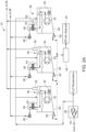
- a wastewater treatment system shown generally as 10 includes a series of components to separate and reduce raw sewage into disposable solids and reusable liquids brought to the system by a building plumbing system.
- the raw sewage is first deposited into one or more pretreatment tanks 12 that function as septic tanks to separate grease, grit and primary solids from the liquid component of the wastewater.
- the solids component is shipped offsite according to means used with conventional septic systems as is known in the art.
- the clarified liquid component is transferred via pipe system to one or more flow equalization tanks 14 that each include one or more influent pumps 16. Pumps 16 are used to force the clarified liquid through a fine screen 18 before further transfer in system 10. Fine screen 18 has a mesh selected for the particular solids being filtered out as is well known in the art.
- any particulate matter filtered out by screen 18 is shipped offsite with the solids component derived from pretreatment tank(s) 12.
- An optional influent composite sampling tap 22 may be placed in the piping system downstream of screen 18 to monitor the composition of the clarified and filtered liquid or influent before entry into other components of system 10 downstream of screen 18.
- influent as used in this context concerns fluids to be introduced into an evaporator component of system 10. This permits adjustment of the pretreatment tank(s) and filter screen to produce influent with the degree of clarity necessary to meet state, federal and local requirements.
- a finer mesh screen will retain smaller particles and result in clearer/cleaner water.
- use of a coarser mesh screen will not retain smaller particles and result in cloudier/less clean water.
- Bioreactor 23 is a multi-component subassembly with an anoxic zone 24, waste activated sludge holding and storage zone 26, a first membrane bioreactor basin 30 and a second membrane bioreactor basin 28.
- the four separate treatment zones each further reduce particulate matter in the influent to further clear the fluids.
- the clarified liquid first enters anoxic zone 24 to remove any dissolved oxygen in the liquid. Once the liquid has been cycled through anoxic zone 24, it is transferred through bioreactor 23 via one or more transfer pumps 32 incorporated into bioreactor 23.
- the oxygen-depleted liquid or influent is moved by transfer pump(s) 32 from anoxic zone 24 to membrane basins 28 and 30.
- Membrane basins 28 and 30 each include one or more filter membrane units that further filter out particulate matter in the clarified liquid.
- One or more blowers 34 flow pressurized air into the membrane basins to create a positive pressure environment to increase the filter rate of the membrane basins. Blowers 34 also flow pressurized air into anoxic zone 24 and WAS holding zone 26 to also increase the pressure in the bioreactor segments to improve flow through bioreactor 23.
- the filtrate or permeate component of the filtered liquid is drawn into a clean-in-place unit 36 by one or more inline permeate pumps 38. Pumps 38 urge the filtrate or permeate into one or more ultraviolet disinfection units 40. Once treated in the UV disinfection unit(s) 40, the treated liquid is transferred to an effluent storage tank 44 to await further processing. An effluent 24-hour composite sampling tap 42 is connected to the line between units 40 and storage tank 44 to permit round-the-clock sampling and evaluation of the treated liquid.
- water vapor condensed by air conditioning units in the building(s) serviced by the wastewater treatment system can be piped directly into the wastewater treatment system.
- the captured water can be transferred directly into the line feeding the UV disinfection unit(s) 40.
- the location of the transfer can be before or after the inline permeate pumps 38.
- Water condensed by air conditioners are commonly fed into a building's sewer line. By transferring AC condensed water to the wastewater treatment system 10, water that would otherwise be lost down a sewer line can be captured, purified and reused as disclosed herein.
- the component is pumped out of membrane basins 28 and 29 into a WAS holding zone 26 via waste-activated sludge pumps 33.
- the contents of the holding compartment 26 is removed from the compartment and taken offsite for disposal 20 along with the screened particulate matter previously described.
- the particulate or sludge component may be treated with an optional microwave unit to degrade and destroy at least some of the harmful biological and chemical materials and compounds resident in the sludge.
- an optional microwave unit As shown in FIG. 1B , a microwave unit 63 is positioned in-line with screen 18 and WAS holding zone 26. This ensures the sludge material shipped off-site is as inert as possible before final disposal.
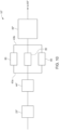
- Effluent pumps 46 positioned in effluent storage tank 44 pump the treated liquid stored in the tank onto one of two tracks.
- the first track is for reuse as toilet water if the treated liquid meets the requirements for classification as Class A reclaimed water.
- a dedicated pipe system (not shown) connects storage tank 44 to one or more toilets, laundry rooms, A/C units, etc. in a building, as allowed by federal, state and local regulations and ordinances, to provide the reclaimed water for use.
- a secondary line from the main water lines is also used in the event there is insufficient reclaimed water to meet usage rates. It is anticipated that 30% of the treated effluent may be used for this purpose. Otherwise, or in addition thereto, the treated effluent can be transferred to one or more thermal evaporators 48 for further processing via a second branching pipe line from storage tank 44.
- thermal evaporators 48 are connected to storage tank 44 to further separate any particulate matter from the liquid component of the effluent.
- Thermal evaporators 48 may be atmospheric evaporators such as those sold by Encon Industries, (Keene, NH), or vacuum-distilled-type evaporators such as those sold by Condorchem Envitech (Barcelona, Spain), that perform the evaporation function at much lower temperatures than atmospheric evaporators, i.e., much lower than the 100°C (212°F) temperature needed by atmospheric evaporators, due to the very low pressure in the vacuum evaporator system.
- atmospheric evaporators such as those sold by Encon Industries, (Keene, NH)
- vacuum-distilled-type evaporators such as those sold by Condorchem Envitech (Barcelona, Spain
- Any type of evaporator may be structured to function as a distillation unit in which the evaporated liquids are condensed and captured for reuse. Any type of evaporator may be structured also as a pure evaporator in which the liquids are completely vaporized and allowed to escape to the atmosphere. It has been found that use of a thermal vacuum evaporator is especially advantageous with an autoclave unit which is incorporated into the wastewater treatment system as disclosed hereinbelow.
- Each thermal evaporator has a fuel source and a burner 50. Natural gas is the preferred fuel source as its combustion byproducts of CO 2 and H 2 O are usable in further processing steps disclosed hereinbelow. It should be understood that other fuel sources may be used to run the thermal evaporators such as electricity and fuel oil among others known in the art. If electricity is used, solar panels and passive electricity generation are the preferable source of the electricity.
- Treated effluent is transferred into the thermal evaporator(s) 48 and exposed to high heat via a heat exchanger 52. The heat exchanger causes the liquid component of the treated effluent to evaporate and travel upwardly into stack 54. Any particulate component separated from the liquid phase gets deposited on a sloped surface 60 that directs the particulates to an evaporator pump 62. Pump 62 forces the particulates to a residual's storage tank 64 for eventual disposal offsite.
- the particulate or sludge component derived from evaporator(s) 48 may be sent through an optional microwave unit to degrade and destroy harmful biological and chemical materials and compounds resident in the sludge.
- a microwave unit 63 is positioned in-line with storage tank 64. This ensures the sludge material shipped off-site is as inert as possible before final disposal.
- a single microwave unit 63 may be positioned in-line with screen 18, WAS holding zone 26 and storage tank 64 to pre-treat all the particulates and sludge produced by filtration sub-system and evaporator sub-system.
- the evaporated liquid component which is almost 100% water vapor passes through a mist capture system 56.
- the water vapor next travels upwardly through a vent stack 58 that leads to a condenser 66 disclosed in more detail herein.
- the water vapor is essentially distilled water in vapor form. Any volatiles present in the effluent at the beginning of the process are removed prior to the treated effluent reaching storage tank 44 via the mist capturing device in the stacks of the atmospheric eliminator. With the autoclave unit(s) present and utilized, all the volatiles and other inorganic and organic compounds will have been destroyed before evaporation.
- Condenser 66 converts the water vapor to liquid water.
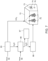
- a water storage tank 68 receives the water for partial use to irrigate carbon-capturing plants 70 planted in a greenhouse or hydroponic system 72. If a conventional greenhouse is used, water will be supplied with a sprayer or similar system. If a hydroponic system, the water will be added to the water supply of the hydroponic system, as needed.
- Greenhouse or hydroponic system 72 is an enclosure with at least one outlet 73 for the ingress and egress of air.
- a second outlet includes reversible fan 74 permits the relative pressure within greenhouse 72 to be positive or negative depending upon the processes being performed in the greenhouse or hydroponic system.
- a series of pipe and tubes extend from water storage tank 68 to provide regulated amounts of water to the individual plants 70. The water dissemination may be computer controlled to set parameters.
- the balance of water stored in the food-grade storage tank may be directed and reused for other purposes in the building including replenishing water in rooftop A/C units, toilets, laundry room, on-site swimming pools, irrigation systems and offsite sale such as for offsite swimming pool water, irrigation systems, etc. Before reusing or redirecting the reclaimed water, it may require additional treatment(s) with ozonation, UV light and/or chlorination depending upon relevant federal, state and local regulations and ordinances.
- the combustion components of the natural gas i.e., CO 2 and H 2 O are transferred via a dedicated vent 59 to a separator 65 used to separate the CO 2 from the H 2 O.
- the H 2 O is transferred via pipe to condenser 66 so as to be combined with the water vapor component derived from the heat exchange process performed on the treated effluent.
- the CO 2 component is transferred via a dedicated pipeline into greenhouse 72.
- the water can be run through an ozonator unit 69 as shown in FIG. 3B .
- ozonation of water is an effective treatment for eliminating bromides and other harmful substances in water.
- a sampling port will be installed in the piping before and after treatment and before storage in order to test for total coliform, E. coli, heterotrophic plate counts (HPCs).
- a UV unit 40 is positioned inline between condenser 66 and water holding tank 68 to ensure no bacteria or other potential pathogens are present in the water as a condition of reuse.
- Use of UV unit 40 may be enhanced also with the application of chlorination as an auxiliary purification source as is well known in the art to be a precondition of reusing the reclaimed water under some federal, state and/or local ordinances.
- the plants 70 are exposed to the CO 2 in order to absorb the CO 2 to perform the carbon-capture function.
- CO 2 from the combustion of natural gas is introduced into greenhouse 72, the relative pressure of the greenhouse atmosphere is kept either neutral of slightly positive relative to the ambient atmospheric pressure outside the greenhouse. This is accomplished with fan 74.
- fan 74 is operated to create a negative pressure in the greenhouse so as to pull carbon-dioxide-laden outside air into the greenhouse. This permits plants 70 to extract the CO 2 from the air and maintain their natural function to continue to capture and assimilate CO 2 .
- At least one CO 2 monitor 76 is placed in greenhouse 72 to ensure human-acceptable levels are maintained.
- Current average atmospheric levels run between about 350 to 400 parts per million concentration in air (depending on altitude).
- the system is designed to constantly monitor CO 2 concentration. If CO 2 levels are too high, fan 74 can be activated to blow the greenhouse air out into the atmosphere until an acceptable level of CO 2 is reached.
- the parameters used to set the CO 2 can be modified as needed for a particular application.
- the system may be designed with a default setting of blowing air out of greenhouse 72 in the event of a system failure to prevent carbon dioxide buildup.
- evaporator unit(s) 48 are used to completely evaporate the water component of the wastewater, separator 65, condenser 66, ozonation unit 69 and greenhouse 72 can be eliminated from system 10. If the energy source used to run evaporator unit(s) 48 is electric, the CO 2 capture components also are not needed and can be eliminated from system 10.
- a wastewater treatment system shown generally as 10" includes a series of components to separate and reduce raw sewage into disposable solids and reusable liquids brought to the system by a building plumbing system and the addition of one or more continuous-cycle autoclave units.
- the autoclave unit destroys harmful chemical compounds such as PFAS into inert compounds to ensure water removed from system 10" is essentially free of any harmful chemical compounds as well as any organic and microbial pathogens.
- identical reference characters having differently primed or unprimed variations and assigned to features are intended to identify different embodiments of the same feature.
- the raw sewage is first deposited into one or more pretreatment tanks 12" that function as septic tanks to separate grease, grit and primary solids from the liquid component of the wastewater.
- the solids component is shipped offsite according to means used with conventional septic systems as is known in the art.
- the clarified liquid component is transferred via pipe system to one or more flow equalization tanks 14" that each include one or more influent pumps 16". Pumps 16" are used to force the clarified liquid through a fine screen 18" before further transfer in system 10".
- any particulate matter filtered out by screen 18" is shipped offsite with the solids component derived from pretreatment tank(s) 12".
- An optional influent composite sampling tap 22" may be placed in the piping system downstream of screen 18" to monitor the composition of the clarified and filtered liquid or influent before entry into other components of system 10" downstream of screen 18".
- influent as used in this context concerns fluids to be introduced into an evaporator component of system 10". This permits adjustment of the pretreatment tank(s) and filter screen to produce influent with the degree of clarity necessary to meet state, federal and local requirements.
- Bioreactor 23 is a multi-component subassembly with an anoxic zone 24", waste activated sludge holding and storage zone 26", a first membrane bioreactor basin 30" and a second membrane bioreactor basin 28".
- the four separate treatment zones each further reduce particulate matter in the influent to further clear the fluids.
- the clarified liquid first enters anoxic zone 24" to remove any dissolved oxygen in the liquid. Once the liquid has been cycled through anoxic zone 24", it is transferred through bioreactor 23" via one or more transfer pumps 32" incorporated into bioreactor 23".
- the oxygen-depleted liquid or influent is moved by transfer pump(s) 32" from anoxic zone 24" to membrane basins 28" and 30".
- Membrane basins 28" and 30" each include one or more filter membrane units that further filter out particulate matter in the clarified liquid.
- One or more blowers 34" flow pressurized air into the membrane basins to create a positive pressure environment to increase the filter rate of the membrane basins. Blowers 34" also flow pressurized air into anoxic zone 24" and WAS holding zone 26" to also increase the pressure in the bioreactor segments to improve flow through bioreactor 23".
- the filtrate or permeate component of the filtered liquid is drawn into a clean-in-place unit 36" by one or more inline permeate pumps 38".
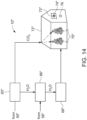
- Pumps 38" urge the filtrate or permeate into ultraviolet disinfection units 40" ("UV disinfection units"). Once treated with ultraviolet light in the UV disinfection units 40", the treated liquid is transferred to a continuous-cycle autoclave 80.
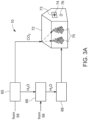
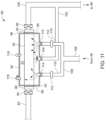
- autoclave unit 80 includes an inlet pipe 82 for transferring the treated liquid to the autoclave.
- Inlet pipe 82 may be formed from 304 stainless steel piping.
- An automatic inlet valve 84 positioned in line with inlet pipe 82 controls the flow of treated liquid into the autoclave unit. Valve 84 may be manual or automated.
- An inlet collar 86 secured to an end of inlet pipe 82 transitions the pipe to a proximal end of an autoclave pipe 92.
- Inlet collar 86 and autoclave pipe 92 both may be fabricated from 316 stainless steel and can be connected using NPT threading as is known in the art.
- a distal end of autoclave pipe 92 is secured to an outlet collar 94 (which can be connected via NPT threading) that transitions the autoclave pipe 92 to outlet pipe 100 and to an outlet automated valve.
- Outlet pipe 100 is connected to an effluent tank 44'.
- An outlet valve 96 positioned in line with outlet pipe 100 controls the flow of treated liquid out of the autoclave unit.
- Valve 96 may be automated in synchronized fashion with valve 84. The purpose of activating both valves automatically and in sync is to ensure proper control of the treatment time within the autoclave so that the desired temperature (approximately 204°C (approximately 400°F)) and pressure (approximately 1. 3 to 2.1 bar (approximately 20-30 psi)) are achieved for approximately 20-25 minutes.
- an autoclave jacket 90 is formed about autoclave pipe 92.
- autoclave jacket 90 is cylindrical and superposed about autoclave pipe 92 to create an annular chamber 91 around the pipe.
- An inlet jacket end 93 is sealed around autoclave pipe 92 with an inlet gasket 88.
- Inlet gasket 88 is structured to withstand the high temperatures and pressures of the autoclave unit 80.
- An outlet jacket end 95 is sealed around autoclave pipe 92 with an outlet gasket 98.
- Outlet gasket 98 is structured to withstand the high temperatures and pressures of autoclave unit 80.
- the inlet collar 86 and outlet collar 94 are constructed such as to ensure the containment of the pressure and temperature according to boiler standards ASME.
- Autoclave jacket 90 and its associated structures may be insulated to maximize the efficiency of the autoclave unit 80.
- Autoclave unit 80 is structured to generate temperatures between 204.4°C and 315.6°C (400°F and 600°F) and pressures between 1.38 bar (20 psi) and 2.07 bar (30 psi) within autoclave pipe 92.
- steam generated by evaporator(s) 48 is fed into chamber 91 with a series of pipes.
- a main delivery pipe 106 attached to, and in fluid communication with, evaporator(s) 48 splits into two or more secondary steam delivery pipes 110 that feed directly into jacket 90.
- Pressure regulators 112 are positioned in line with secondary delivery pipes 110 to control the pressure generated in jacket 90 that directly affects the pressure in autoclave pipe 92.
- Steam supply valves 114 control the flow of steam into jacket 90.
- One or more steam exhaust pipes 102 are secured to jacket 90 and in fluid communication with chamber 91 to relieve or remove pressure from the autoclave unit 80.
- An exhaust valve 104 controls the flow of steam out of jacket 90.
- An optional screen 105 may be placed at the jacket/exhaust pipe junction to prevent any contaminants in jacket 90 from being passed to evaporator(s) 48.
- a distal end of exhaust pipe(s) 102 are connected directly or indirectly to evaporator(s) 48.
- Safety valve 116 is secured to jacket 90.
- Safety valve 116 may be in the form of a pressure/temperature valve used on an oil-fired furnace to bleed off steam if the temperature and/or pressure exceed preselected ceiling values.
- a pressure and/or temperature gauge may also be secured to jacket 90 to monitor the pressure and/or temperature within jacket 90. Control of the temperature and pressure within jacket 90 may be automated and coordinated with the various valves used to introduce effluent into autoclave 80 as well as the valves used to introduce steam into the autoclave and to release steam from the autoclave.
- electrically-generated heat may be used to increase the temperature and pressure within autoclave 80 to the desired levels for chemical compound destruction.
- a heating wire or thermostatic system 97 is coiled around autoclave pipe 92.
- UV unit(s) 40 are eliminated from the system. This is made possible by autoclave unit 80 that can destroy and degrade any organic and microbial life and microscopic pathogens that would otherwise be degraded and possibly destroyed by UV unit(s) 40 or ozonation. Any effluent treated in autoclave unit 80 will be sufficiently inert for further processing by evaporator unit(s) 48".
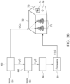
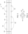
- a plurality of autoclave units 80 are arranged in parallel with an autoclave manifold.
- An intake manifold 43a connected after the filtration system or the optional UV unit(s) directs effluent treated in the filtration system and the optional UV unit(s) 40" into the multiple autoclave units 80 from the post-treatment storage tank and before the autoclave unit(s).
- Intake manifold 43a may include valves dedicated to each branch of the manifold to selectively direct effluent to one or more autoclave units as needed to handle the particular effluent volume in a given time.
- the valves also function as inlet valves 84 to close off the autoclave unit(s) when in use.
- Having multiple autoclave units also provides the ability to take one or more offline for servicing while leaving one or more units online to handle effluent loads.
- an outtake manifold 43b Prior to connecting the multiple autoclave units 80 to evaporator unit(s) 48", an outtake manifold 43b has dedicated ports for each autoclave unit 80 to deliver the treated effluent downstream from the autoclave units 80.
- Outtake manifold 43b may include valves 96 dedicated to each branch of the outtake manifold to selectively close an autoclave unit in operation. Once the effluent treatment operation is completed, the valve is opened and the treated effluent is directed to evaporator unit(s) 48".
- an effluent storage tank 44" to await further processing.
- An effluent 24-hour composite sampling tap 42" is connected to the line between units 40" and storage tank 44" to permit round-the-clock sampling and evaluation of the treated liquid.
- the particulate or sludge component derived from the filtration of the clarified liquid is pumped out of membrane basins 28" and 29" into a WAS holding zone 26" via waste-activated sludge pumps 33".
- the contents of the holding compartment 26" is removed from the compartment and taken offsite for disposal 20" along with the screened particulate matter previously described.
- Effluent pumps 46" positioned in effluent storage tank 44" pump the treated liquid stored in the tank onto one of two tracks.
- the first track is for reuse as toilet water as the treated liquid meets the requirements for classification as Class A reclaimed water as required by EPA standards and local environmental regulations.
- a dedicated pipe system connects storage tank 44" to one or more toilets in a building to provide the reclaimed water for use or for other uses allowed for reusable water.
- a secondary line from the main water lines is also used in the event there is insufficient reclaimed water to meet usage rates. It is anticipated that 30% of the treated effluent may be used for this purpose. Otherwise, or in addition thereto, the treated effluent can be transferred to one or more thermal evaporators 48" for further processing via a second branching pipe line from storage tank 44".
- thermal evaporators 48" are connected to storage tank 44" to further separate any particulate matter from the liquid component of the effluent.
- Each thermal evaporator has a fuel source and a burner 50". Natural gas is the preferred fuel source as its combustion byproducts of CO 2 and H 2 O are usable in further processing steps disclosed hereinbelow. It should be understood other fuel sources may be used to run the thermal evaporators such as electricity and fuel oil among others known in the art. If electricity is used, solar panels and passive electricity generation are the preferable source of the electricity.
- Treated effluent is transferred into the thermal evaporator(s) 48" and exposed to high heat via a heat exchanger 52".
- the heat exchanger causes the liquid component of the treated effluent to evaporate and travel upwardly into stack 54". Any particulate/sludge component separated from the liquid phase gets deposited on a sloped surface 60" that directs the particulates to an evaporator pump 62". Pump 62" forces the particulates to a residual's storage tank 64" for eventual disposal offsite.
- the evaporated liquid component which is almost 100% water vapor passes through a mist capturing system 56".
- the water vapor next travels upwardly through a vent stack 58" that leads to a condenser 66" disclosed in more detail herein.
- the water vapor is essentially distilled water in vapor form. Any volatiles present in the effluent at the beginning of the process are removed prior to the treated effluent reaching storage tank 44" via the mist capturing system 56.
- Condenser 66" converts the water vapor to liquid water.
- a water storage tank 68" (which may be a food-grade storage tank), receives the water for partial use to irrigate carbon-capturing plants 70" planted in a greenhouse 72".
- Greenhouse 72" is an enclosure with at least one outlet 73" for the ingress and egress of air.
- a second outlet includes reversible fan 74" permits the relative pressure within greenhouse 72" to be positive or negative depending upon the processes being performed in the greenhouse.
- a series of pipe and tubes extend from water storage tank 68" to provide regulated amounts of water to the individual plants 70". The water dissemination may be computer controlled to set parameters.
- the combustion components of the natural gas i.e., CO 2 and H 2 O are transferred via a dedicated vent 59" to a separator 65" used to separate the CO 2 from the H 2 O.
- the H 2 O is transferred via pipe to condenser 66" so as to be combined with the water vapor component derived from the heat exchange process performed on the treated effluent.
- the CO 2 component is transferred via a dedicated pipeline into greenhouse 72".
- the plants 70" are exposed to the CO 2 in order to absorb the CO 2 to perform the carbon-capture function.
- CO 2 from the combustion of natural gas is introduced into greenhouse 72"
- the relative pressure of the greenhouse atmosphere is kept either neutral of slightly positive relative to the ambient atmospheric pressure outside the greenhouse. This is accomplished with fan 74".
- fan 74" is operated to create a negative pressure in the greenhouse so as to pull carbon-dioxide-laden outside air into the greenhouse. This permits plants 70" to extract the CO 2 from the air and maintain their natural function to continue to capture and assimilate CO 2 .
- At least one CO 2 monitor 76" is placed in greenhouse 72" to ensure human-acceptable levels are maintained.
- Current average atmospheric levels run between about 350 to 400 parts per million concentration in air (depending on altitude).
- the system is designed to constantly monitor CO 2 concentration. If CO 2 levels are too high, fan 74" can be activated to blow the greenhouse air out into the atmosphere until an acceptable level of CO 2 is reached.
- the parameters used to set the CO 2 can be modified as needed for a particular application.
- the system may be designed with a default setting of blowing air out of greenhouse 72" in the event of a system failure to prevent carbon dioxide buildup.
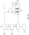
- one or more sonolysis units may be incorporated into the wastewater treatment system, designated generally as 10′′′ in addition to autoclave unit(s) 80 .
- a sonolysis unit, shown designated generally as 47 provides an additional means to destroy and degrade pathogenic microbial life and hazardous chemical compounds.
- Sonolysis unit 47 includes a sonolysis tube 100 made from a rigid material such as stainless steel to withstand the high-heat and temperature environment of the unit.
- Unit 47 is coaxially arranged in a cylindrical outer jacket 102 that supports a plurality of sound transducers 104. The transducers may be positioned equidistantly along the length of jacket 102.
- Valves 106 positioned at the ends of tube 100 permit the controlled entry and exit of effluent for treatment. Valves 106 are synchronized to permit the entry of a bolus of fluid for treatment and the exit of the bolus of fluid after treatment. The valves are synchronized like the valves of the autoclave unit.
- An annular chamber formed between sonolysis tube 100 and jacket 102 is filled with a liquid to enhance the energy transfer when sound transducers 104 are activated.
- the sound waves produced create cavitation of the effluent in tube 100, which forms bubbles within tube 100.
- the bubbles form in an adiabatic environment in which the temperature and pressures within the bubbles can reach 5000 °C and twenty times atmospheric pressure while the temperature and pressure of the effluent can remain at atmospheric levels. This high-heat, high-pressure environment of the bubbles destroys any chemical compounds caught in the bubbles.
- the effluent is exposed to the sonolysis procedure for approximately 20 minutes or more. After the designated time, the treated effluent is transferred out of the tube an into evaporator unit(s) 48′′′.
Landscapes
- Chemical & Material Sciences (AREA)
- Engineering & Computer Science (AREA)
- Life Sciences & Earth Sciences (AREA)
- Environmental & Geological Engineering (AREA)
- Water Supply & Treatment (AREA)
- Hydrology & Water Resources (AREA)
- Organic Chemistry (AREA)
- Chemical Kinetics & Catalysis (AREA)
- Toxicology (AREA)
- Health & Medical Sciences (AREA)
- Mechanical Engineering (AREA)
- Biodiversity & Conservation Biology (AREA)
- Microbiology (AREA)
- Physical Water Treatments (AREA)
- Treatment Of Water By Oxidation Or Reduction (AREA)
- Heat Treatment Of Water, Waste Water Or Sewage (AREA)
- Activated Sludge Processes (AREA)
- Purification Treatments By Anaerobic Or Anaerobic And Aerobic Bacteria Or Animals (AREA)
- Separation Using Semi-Permeable Membranes (AREA)
- Electrical Discharge Machining, Electrochemical Machining, And Combined Machining (AREA)
Claims (11)
- Abwasserbehandlungs- und -managementsystem (10; 10'; 10"), umfassend:mindestens einen Vorbehandlungstank (12; 12") zum Aufnehmen von Rohabwasser, wobei der mindestens eine Vorbehandlungstank (12; 12") Fett, Sand und primäre Feststoffe von der flüssigen Komponente des Abwassers trennt;mindestens einen Strömungsausgleichstank (14; 14"), der über eine Rohrleitung mit dem mindestens einen Vorbehandlungstank (12; 12") verbunden ist, wobei der Strömungsausgleichstank (14; 14") in Fluidverbindung mit dem mindestens einen Vorbehandlungstank (12; 12") steht;mindestens eine Zulaufpumpe (16; 16"), die über Rohrleitungen mit dem mindestens einen Strömungsausgleichstank (14; 14") verbunden ist;mindestens ein Sieb (18; 18"), das über Rohrleitungen mit der Zulaufpumpe (16; 16") und dem Strömungsausgleichstank (14; 14") verbunden ist, wobei das mindestens eine Sieb (16; 16") zusätzliche Feststoffe aus den Flüssigkeiten herausfiltert;mindestens einen Membranbioreaktor (23; 23"), der über Rohrleitungen mit dem mindestens einen Sieb (18; 18") verbunden ist, wobei der mindestens eine Membranbioreaktor (23; 23") die Flüssigkeiten filtert;mindestens eine Pumpe (38; 38"), die über Rohrleitungen mit dem mindestens einen Membranbioreaktor (23; 23") verbunden und diesem nachgeschaltet ist;mindestens einen Schmutzwasserspeichertank (44, 44', 44"), der über Rohrleitungen mit der mindestens einen Pumpe (38; 38") verbunden ist und dieser nachgeschaltet ist;gekennzeichnet durch mindestens einen Autoklav (80), der über Rohrleitungen mit dem mindestens einen Schmutzwasserspeichertank (44, 44', 44") verbunden und diesem nachgeschaltet ist, wobei der mindestens eine Autoklav (80) eine Autoklavenleitung (92) umfasst, wobei die Autoklavenleitung (92) einen Einlasskragen (86) an einem proximalen Ende der Autoklavenleitung (92), einen Auslasskragen (94) an einem distalen Ende der Autoklavenleitung (92) und ferner einen Autoklavenmantel (90) aufweist, der um die Autoklavenleitung (92) herum befestigt ist, wobei der Autoklavenmantel (90) ferner an den Enden der Autoklavenleitung (92) mit einem Einlassmantelende (93), das an einem Einlassende der Autoklavenleitung (92) befestigt ist, und einem Auslassmantelende (95), das an einem Auslassende der Autoklavenleitung (92) befestigt ist, befestigt ist, wobei die Kombination des Autoklavenmantels (90), des Einlassmantelendes (93), des Auslassmantelendes (95) und der Autoklavenleitung eine Kammer (91) in dem mindestens einen Autoklav (80) bilden, wobei ein Einlassventil (84) einem proximalen Ende der Autoklavenleitung (92) vorgeschaltet und ein Auslassventil (96) einem distalen Endes der Autoklavenleitung (92) nachgeschaltet positioniert ist, wobei das Einlassventil (84) und das Auslassventil (96) in Fluidverbindung mit der Autoklavenleitung (92) stehen; undmindestens einen thermischen Verdampfer (48, 48', 48"), der über Rohrleitungen mit dem mindestens einen Autoklav (80) verbunden und diesem nachgeschaltet ist, wobei der mindestens eine Autoklav (80) ferner eine Hauptzuführungsleitung (106) umfasst, die an einem Ende an dem mindestens einen thermischen Verdampfer (48, 48', 48") befestigt ist, wobei die Hauptzuführungsleitung (106) in mindestens zwei sekundäre Dampfzuführungsleitungen (110) aufgeteilt ist, die jeweils direkt am Autoklavenmantel (90) befestigt sind, wobei die Hauptzuführungsleitung (106) und die mindestens zwei sekundären Dampfzuführungsleitungen (110) in Fluidverbindung mit der Kammer (91) und dem mindestens einen thermischen Verdampfer (48, 48', 48") stehen, wobei Dampfzufuhrventile (114) an den mindestens zwei sekundären Dampfzuführungsleitungen (110) befestigt sind, um den Dampfstrom in den Autoklavenmantel (90) zu steuern, wobei Druckregler (112) in Reihe mit den mindestens zwei sekundären Dampfzuführungsleitungen (110) befestigt sind, wobei der mindestens eine Autoklav (80) ferner mindestens eine Dampfauslassleitung (102) umfasst, die an einem Ende an dem Autoklavenmantel (90) befestigt ist und an einem distalen Ende direkt oder indirekt an dem mindestens einen Verdampfer (48, 48', 48") befestigt ist, wobei ein Auslassventil (104) an der mindestens einen Dampfauslassleitung (102) befestigt ist, um den Dampfstrom aus dem Autoklavenmantel (90) zu steuern.
- Abwasserbehandlungs- und -managementsystem (10; 10'; 10") nach Anspruch 1, wobei der mindestens eine Autoklav (80) ferner ein Temperatur-/Druckbegrenzungsventil (116) und einen Druckregler (112) umfasst, die an dem Autoklavenmantel (90) befestigt sind.
- Abwasserbehandlungs- und -managementsystem (10; 10'; 10") nach Anspruch 1, ferner umfassend:
mindestens eine Sonolyseeinheit (47), die an das Abwasserbehandlungs- und -managementsystem (10; 10'; 10) angeschlossen ist. - Abwasserbehandlungs- und -managementsystem (10; 10'; 10") nach Anspruch 1 oder 3, ferner umfassend mindestens eine Ultraviolett-Desinfektionseinheit (40, 40"), die über Rohrleitungen mit der mindestens einen Pumpe (38; 38") verbunden ist und dieser nachgeschaltet ist, und über Rohrleitungen mit dem mindestens einen Schmutzwasserspeichertank (44, 44', 44") verbunden ist und diesem vorgeschaltet ist, wobei in der mindestens einen Ultraviolett-Desinfektionseinheit (40, 40") behandelten Fluide in den Schmutzwasserspeichertank (44, 44', 44") überführt werden.
- Abwasserbehandlungs- und -managementsystem (10; 10'; 10") nach Anspruch 3, wobei die mindestens eine Sonolyseeinheit (47) ein Sonolyserohr (100) mit einem Innenraum umfasst, wobei das Sonolyserohr (100) in einem Außenmantel (102) befestigt ist, wobei die mindestens eine Sonolyseeinheit (47) ferner eine Vielzahl von Schallwandlern (104) umfasst, die in dem Außenmantel (102) befestigt sind.
- Abwasserbehandlungs- und -managementsystem (10; 10'; 10") nach Anspruch 5, wobei die mindestens eine Sonolyseeinheit (47) mindestens zwei Ventile (106) umfasst, ein vorgeschaltetes Ventil, das der mindestens einen Sonolyseeinheit (47) vorgeschaltet ist, und ein nachgeschaltetes Ventil, das der mindestens einen Sonolyseeinheit (47) nachgeschaltet ist, wobei die vorgeschalteten und nachgeschalteten Ventile in Fluidverbindung mit dem Inneren des Sonolyserohrs (100) stehen.
- Abwasserbehandlungs- und -managementsystem (10; 10'; 10") nach Anspruch 1 oder 3, ferner umfassend einen Kondensator (66, 66"), der über Rohrleitungen mit dem mindestens einen thermischen Verdampfer (48, 48', 48") verbunden ist und diesem nachgeschaltet ist, um von dem mindestens einen Verdampfer (48, 48', 48") erzeugten Wasserdampf zu kondensieren.
- Abwasserbehandlungs- und -managementsystem (10; 10'; 10") nach Anspruch 7, ferner umfassend einen Wasserspeichertank (68, 68"), der über Rohrleitungen mit dem mindestens einen Kondensator (66, 66") verbunden und diesem nachgeschaltet ist, um Wasserdampf aufzunehmen, der von dem mindestens einen Kondensator (66, 66") zu Wasser kondensiert wird.
- Abwasserbehandlungs- und -managementsystem (10; 10'; 10") nach Anspruch 8, ferner umfassend ein Gewächshaus (72, 72"), das über Rohrleitungen dem Wasserspeichertank (68, 68") nachgeschaltet ist und kohlenstoffbindende Pflanzen (70, 70") enthält, um Wasser aus dem Wasserspeichertank (68, 68") aufzunehmen.
- Abwasserbehandlungs- und -managementsystem (10, 10', 10") nach Anspruch 9, ferner umfassend einen Abscheider (65, 65"), der über Rohrleitungen mit dem mindestens einen thermischen Verdampfer (48, 48', 48") verbunden ist und diesem nachgeschaltet ist, um Wasserdampf und Kohlendioxid zu trennen, die durch den Betrieb des mindestens einen Verdampfers (48, 48', 48") entstehen, wobei das durch den Abscheider (65, 65") abgetrennte Wasser über Rohrleitungen zu dem Kondensator (66, 66") und das Kohlendioxid über Rohrleitungen zu dem Gewächshaus (72, 72") geleitet wird.
- Abwasserbehandlungs- und -managementsystem (10, 10', 10") nach Anspruch 9 oder 10, wobei das Gewächshaus (72, 72") einen Ventilator (74, 74") einschließt, um den relativen Druck in dem Gewächshaus auf positiv oder negativ einzustellen.
Applications Claiming Priority (2)
| Application Number | Priority Date | Filing Date | Title |
|---|---|---|---|
| US201962839901P | 2019-04-29 | 2019-04-29 | |
| PCT/US2020/030498 WO2020223366A1 (en) | 2019-04-29 | 2020-04-29 | Zero discharge water treatment apparatus and method |
Publications (3)
| Publication Number | Publication Date |
|---|---|
| EP3962865A1 EP3962865A1 (de) | 2022-03-09 |
| EP3962865A4 EP3962865A4 (de) | 2023-02-08 |
| EP3962865B1 true EP3962865B1 (de) | 2025-03-19 |
Family
ID=72922056
Family Applications (2)
| Application Number | Title | Priority Date | Filing Date |
|---|---|---|---|
| EP20798233.1A Active EP3962865B1 (de) | 2019-04-29 | 2020-04-29 | System zur abflussfreien wasserbehandlung |
| EP21929398.2A Pending EP4301706A4 (de) | 2019-04-29 | 2021-11-04 | Vorrichtung und verfahren zur wasserbehandlung ohne abfluss |
Family Applications After (1)
| Application Number | Title | Priority Date | Filing Date |
|---|---|---|---|
| EP21929398.2A Pending EP4301706A4 (de) | 2019-04-29 | 2021-11-04 | Vorrichtung und verfahren zur wasserbehandlung ohne abfluss |
Country Status (9)
| Country | Link |
|---|---|
| US (1) | US11390545B2 (de) |
| EP (2) | EP3962865B1 (de) |
| JP (1) | JP7587849B2 (de) |
| KR (1) | KR20210150586A (de) |
| BR (1) | BR112021021697A2 (de) |
| CA (1) | CA3135721A1 (de) |
| IL (1) | IL287695B (de) |
| MX (1) | MX2021013095A (de) |
| WO (3) | WO2020223366A1 (de) |
Families Citing this family (4)
| Publication number | Priority date | Publication date | Assignee | Title |
|---|---|---|---|---|
| US11897787B2 (en) * | 2020-04-29 | 2024-02-13 | Zero Discharge, LLC | Zero discharge water treatment apparatus and method |
| BR112021021697A2 (pt) * | 2019-04-29 | 2022-02-01 | Zero Discharge Llc | Aparelho e método de tratamento de água com zero descarga |
| WO2024124219A1 (en) * | 2022-12-09 | 2024-06-13 | Asrc Energy Services, Llc | Remediation systems and processes |
| CN116874088B (zh) * | 2023-07-18 | 2025-07-18 | 武汉中科水生生态环境股份有限公司 | 废水处理系统及其方法 |
Family Cites Families (56)
| Publication number | Priority date | Publication date | Assignee | Title |
|---|---|---|---|---|
| US3338663A (en) * | 1965-03-24 | 1967-08-29 | American Sterilizer Co | Dual autoclave |
| SE300045B (de) * | 1965-04-29 | 1968-04-01 | Electrolux Ab | |
| US3907679A (en) | 1973-03-26 | 1975-09-23 | Coate Burial Vault Inc | Sewage treatment system including effluent evaporator |
| US3930960A (en) | 1974-05-28 | 1976-01-06 | Taylor Fred W | Evaporator-condenser unit for producing potable water from sewage |
| US4092242A (en) | 1975-06-16 | 1978-05-30 | The Redux Corporation | Waste water purification system |
| ES2064083T4 (es) | 1990-01-23 | 2007-04-01 | Anoxkaldnes As | Metodo y reactor para la purificacion de aguas. |
| US5190659A (en) * | 1990-07-06 | 1993-03-02 | International Environmental Systems Inc. | Contamination removal system employing filtration and plural ultraviolet and chemical treatment steps and treatment mode controller |
| USRE35871E (en) * | 1990-09-04 | 1998-08-18 | Americleer Corporation | Water reclamation system and method |
| US5527454A (en) * | 1994-04-26 | 1996-06-18 | Jacobs Environmental, Inc. | Mechanical ventilation system to capture gases released from wastewater passing through rock media trickling filters |
| JPH0871588A (ja) * | 1994-08-31 | 1996-03-19 | Nippon Parkerizing Co Ltd | シアンを含有する廃液の脱窒素処理方法 |
| SE9502198L (sv) | 1995-06-16 | 1996-12-17 | Eka Chemicals Ab | Upplösning av inkruster vid indunstning av surt och alkaliskt avloppsvatten |
| US6048458A (en) | 1995-12-01 | 2000-04-11 | Eastern Power Limited | Apparatus and method for waste recycling and conversion |
| FR2745001B1 (fr) | 1996-02-16 | 1998-04-17 | Degremont | Reacteur pour l'elimination biologique de la pollution organique des eaux |
| US5787537A (en) | 1996-07-19 | 1998-08-04 | Water Recovery Systems, Inc. | Method of washing laundry and recycling wash water |
| US6517711B1 (en) | 1998-10-02 | 2003-02-11 | Wastech International Inc. | Waste treatment system |
| JP2000354886A (ja) * | 1999-04-15 | 2000-12-26 | Unitika Ltd | 有機性廃水の処理方法及び処理装置 |
| FR2843106B1 (fr) * | 2002-08-05 | 2004-10-08 | Omnium Traitement Valorisa | Procede et installation de traitement des boues provenant des installations d'epuration biologique des eaux |
| US20060057021A1 (en) | 2002-10-15 | 2006-03-16 | Sawyer Melvyn L | Fixed vacuum-insulated saturated steam autoclave |
| US6730223B1 (en) | 2002-11-01 | 2004-05-04 | Comprehensive Resources, Recovery & Reuse, Inc. | Apparatus, system and method for treating waste material |
| US8080163B2 (en) * | 2002-12-04 | 2011-12-20 | Blue Water Technologies, Inc. | Water treatment method |
| US8071055B2 (en) * | 2002-12-04 | 2011-12-06 | Blue Water Technologies, Inc. | Water treatment techniques |
| RU2361910C2 (ru) | 2003-04-25 | 2009-07-20 | 2С-Софистикейтед Системс Лимитед | Способ перегонки |
| WO2006029249A2 (en) | 2004-09-03 | 2006-03-16 | Everest International, Ltd. | Water producing method and apparatus |
| US20060096918A1 (en) * | 2004-11-09 | 2006-05-11 | Semmens Michael J | Biofilm wastewater treatment devices |
| US7968057B2 (en) | 2004-11-23 | 2011-06-28 | Estech Europe Limited | Autoclave |
| GB0503533D0 (en) | 2005-02-21 | 2005-03-30 | Forstmanis Talivaldis | Evaporate for dilute aqueous solutions |
| US7628893B1 (en) | 2005-08-01 | 2009-12-08 | Pure Energy Technology Co | Apparatus and method for separation |
| FR2893935B1 (fr) * | 2005-11-28 | 2008-05-30 | Degremont Sa | Procede et installation de traitement d'effluents charges en micro-organismes. |
| US7531096B2 (en) * | 2005-12-07 | 2009-05-12 | Arizona Public Service Company | System and method of reducing organic contaminants in feed water |
| WO2007103409A2 (en) * | 2006-03-08 | 2007-09-13 | Siemens Water Technologies Corp. | Wastewater treatment system and method |
| US8444861B2 (en) | 2006-08-11 | 2013-05-21 | The University Of British Columbia | Method and apparatus using hydrogen peroxide and microwave system for slurries treatment |
| US8999154B2 (en) * | 2007-08-02 | 2015-04-07 | Ecosphere Technologies, Inc. | Apparatus for treating Lake Okeechobee water |
| US7699988B2 (en) | 2007-08-02 | 2010-04-20 | Ecosphere Technologies, Inc. | Enhanced water treatment for reclamation of waste fluids and increased efficiency treatment of potable waters |
| WO2010000798A1 (en) | 2008-07-04 | 2010-01-07 | Unilever Plc | Waste water treatment |
| WO2011011134A2 (en) | 2009-07-23 | 2011-01-27 | Lorenz Kenneth R | Water recovery systems and methods |
| AU2010304545B2 (en) * | 2009-10-09 | 2013-05-16 | Chiyoda Corporation | Method and system for treating plant wastewater |
| CN102125804A (zh) * | 2010-01-12 | 2011-07-20 | 天津海之凰科技有限公司 | 一种利用非金属导热中空纤维的压汽蒸馏装置及方法 |
| US8871089B2 (en) * | 2010-01-13 | 2014-10-28 | Daniel M. Early | Wastewater treatment system |
| CA2745104C (en) * | 2010-06-29 | 2017-07-18 | Centre De Recherche Industrielle Du Quebec (Criq) | Submerged membrane bioreactor system and biological methods for removing bisphenol compounds from municipal wastewater |
| EP2418176A1 (de) * | 2010-08-12 | 2012-02-15 | Basf Se | Verfahren zur Aufreinigung von Abwässern aus der Aufarbeitung vom rohem Mononitrobenzol |
| US9796612B2 (en) | 2012-06-21 | 2017-10-24 | Eureka Resources, Llc | Method and system for treating wastewater |
| US9593025B2 (en) | 2012-07-13 | 2017-03-14 | Gretchen B. Clark | Wastewater evaporator |
| EP2878581A1 (de) * | 2013-12-02 | 2015-06-03 | Lappeenrannan Teknillinen Yliopisto | Abwasserreinigungssystem |
| CN104955343A (zh) * | 2013-12-16 | 2015-09-30 | 纽特林西克公司 | 处理废物活化污泥的方法 |
| US10920187B2 (en) | 2014-03-25 | 2021-02-16 | Boise State University | Ultraviolet radiation pre-treatment of wastewater, improving its utility for algal cultivation |
| US9945221B2 (en) | 2015-05-07 | 2018-04-17 | Veolia Water Technologies, Inc. | Process for treating produced water evaporator concentrate |
| JP6591224B2 (ja) * | 2015-07-23 | 2019-10-16 | 株式会社東芝 | 処理装置及び処理方法 |
| CN105481189B (zh) * | 2016-01-15 | 2018-03-23 | 沅江精一科技机械制造有限公司 | 船用生活污水处理系统 |
| CN205420096U (zh) * | 2016-03-14 | 2016-08-03 | 龚获 | 一种污水处理装置 |
| CN206544960U (zh) | 2017-02-21 | 2017-10-10 | 东莞市潮景水处理科技有限公司 | 一种废水零排放装置 |
| CN106698863A (zh) * | 2017-03-07 | 2017-05-24 | 哈尔滨盛龙华环保科技发展有限公司 | 用于水冲型移动厕所冲厕污水的内循环处理工艺及系统 |
| CN206635065U (zh) * | 2017-03-31 | 2017-11-14 | 广东怡翔制药有限公司 | 一种改进型热压式蒸馏水机 |
| CN107473298B (zh) * | 2017-09-29 | 2023-04-04 | 曲景春 | 一种高节能型热压式蒸馏水机 |
| CN207775025U (zh) | 2017-12-22 | 2018-08-28 | 南京工大环境科技南通有限公司 | 一种用于麦草畏高含盐废水处理的强化预处理装置 |
| CN109052840B (zh) * | 2018-08-30 | 2021-11-23 | 山东默锐环境产业股份有限公司 | 一种bdp废水多级耦合零排放水处理系统 |
| BR112021021697A2 (pt) * | 2019-04-29 | 2022-02-01 | Zero Discharge Llc | Aparelho e método de tratamento de água com zero descarga |
-
2020
- 2020-04-29 BR BR112021021697A patent/BR112021021697A2/pt not_active Application Discontinuation
- 2020-04-29 IL IL287695A patent/IL287695B/en unknown
- 2020-04-29 CA CA3135721A patent/CA3135721A1/en active Pending
- 2020-04-29 US US16/862,121 patent/US11390545B2/en active Active
- 2020-04-29 EP EP20798233.1A patent/EP3962865B1/de active Active
- 2020-04-29 MX MX2021013095A patent/MX2021013095A/es unknown
- 2020-04-29 KR KR1020217038704A patent/KR20210150586A/ko active Pending
- 2020-04-29 JP JP2021564576A patent/JP7587849B2/ja active Active
- 2020-04-29 WO PCT/US2020/030498 patent/WO2020223366A1/en not_active Ceased
-
2021
- 2021-03-05 WO PCT/US2021/021013 patent/WO2021221792A1/en not_active Ceased
- 2021-11-04 WO PCT/US2021/058142 patent/WO2022186864A1/en not_active Ceased
- 2021-11-04 EP EP21929398.2A patent/EP4301706A4/de active Pending
Also Published As
| Publication number | Publication date |
|---|---|
| WO2022186864A1 (en) | 2022-09-09 |
| EP4301706A4 (de) | 2025-01-29 |
| KR20210150586A (ko) | 2021-12-10 |
| EP3962865A4 (de) | 2023-02-08 |
| WO2020223366A1 (en) | 2020-11-05 |
| EP3962865A1 (de) | 2022-03-09 |
| JP2022532856A (ja) | 2022-07-20 |
| WO2021221792A1 (en) | 2021-11-04 |
| US11390545B2 (en) | 2022-07-19 |
| CA3135721A1 (en) | 2020-11-05 |
| IL287695A (en) | 2021-12-01 |
| US20200339454A1 (en) | 2020-10-29 |
| EP4301706A1 (de) | 2024-01-10 |
| BR112021021697A2 (pt) | 2022-02-01 |
| IL287695B (en) | 2022-09-01 |
| JP7587849B2 (ja) | 2024-11-21 |
| MX2021013095A (es) | 2022-01-24 |
Similar Documents
| Publication | Publication Date | Title |
|---|---|---|
| EP3962865B1 (de) | System zur abflussfreien wasserbehandlung | |
| US8034289B2 (en) | Fluid treatment process and apparatus | |
| US6977047B2 (en) | Method and system for the manufacture of pharmaceutical water | |
| CN107709248A (zh) | 水过滤系统和方法 | |
| KR20190053000A (ko) | 역삼투압 해수 담수화 장치 | |
| GB2509309A (en) | Cooling process | |
| US11420882B2 (en) | Water treatment system and method of use thereof | |
| CN205222857U (zh) | 一种反渗透集装箱式海水淡化装置 | |
| WO1999051867A1 (en) | Improvements in the generation of electricity and the treatment and disposal of sewage | |
| CN1121253C (zh) | 水处理设备和方法 | |
| US11897787B2 (en) | Zero discharge water treatment apparatus and method | |
| US20240343609A1 (en) | Zero Discharge Water Treatment Apparatus and Method | |
| CN217418411U (zh) | 一种新型车载净水设备 | |
| US6648938B1 (en) | Device for cleaning fluid in the form of vapor from a circuit | |
| CN112004590A (zh) | 系统及用于清洁水过滤系统的方法 | |
| CN2820843Y (zh) | 多功能净化水设备 | |
| CN101084162A (zh) | 液体处理装置和处理方法 | |
| CN207175664U (zh) | 一种直饮水系统 | |
| US20240002258A1 (en) | Water reclamation system using oil as a heat transfer medium and liquid salt collector | |
| CN102361822A (zh) | 水净化装置和方法 | |
| US11897802B2 (en) | Continuous, approximately real-time residential wastewater treatment system and apparatus | |
| US8029676B2 (en) | Non-recirculating, self-sanitizing carbon filter system | |
| CN117585834A (zh) | 一种燃煤电厂耦合的海水淡化直饮水处理工艺路线 | |
| CN121085449A (zh) | 一种净水车的净水系统及净水车 | |
| US20200392030A1 (en) | Fluid Treatment System |
Legal Events
| Date | Code | Title | Description |
|---|---|---|---|
| STAA | Information on the status of an ep patent application or granted ep patent |
Free format text: STATUS: THE INTERNATIONAL PUBLICATION HAS BEEN MADE |
|
| PUAI | Public reference made under article 153(3) epc to a published international application that has entered the european phase |
Free format text: ORIGINAL CODE: 0009012 |
|
| STAA | Information on the status of an ep patent application or granted ep patent |
Free format text: STATUS: REQUEST FOR EXAMINATION WAS MADE |
|
| 17P | Request for examination filed |
Effective date: 20211125 |
|
| AK | Designated contracting states |
Kind code of ref document: A1 Designated state(s): AL AT BE BG CH CY CZ DE DK EE ES FI FR GB GR HR HU IE IS IT LI LT LU LV MC MK MT NL NO PL PT RO RS SE SI SK SM TR |
|
| DAV | Request for validation of the european patent (deleted) | ||
| DAX | Request for extension of the european patent (deleted) | ||
| REG | Reference to a national code |
Ref country code: DE Ref legal event code: R079 Free format text: PREVIOUS MAIN CLASS: C02F0001000000 Ipc: C02F0001040000 Ref country code: DE Ref legal event code: R079 Ref document number: 602020048000 Country of ref document: DE Free format text: PREVIOUS MAIN CLASS: C02F0001000000 Ipc: C02F0001040000 |
|
| A4 | Supplementary search report drawn up and despatched |
Effective date: 20230109 |
|
| RIC1 | Information provided on ipc code assigned before grant |
Ipc: C02F 1/16 19800101ALN20230103BHEP Ipc: C02F 1/00 19800101ALN20230103BHEP Ipc: C02F 1/78 19800101ALN20230103BHEP Ipc: C02F 1/76 19800101ALN20230103BHEP Ipc: C02F 1/30 19800101ALN20230103BHEP Ipc: C02F 1/32 19800101ALN20230103BHEP Ipc: C02F 9/00 19800101ALI20230103BHEP Ipc: C02F 3/12 19800101ALI20230103BHEP Ipc: C02F 1/44 19800101ALI20230103BHEP Ipc: C02F 1/36 19800101ALI20230103BHEP Ipc: C02F 1/04 19800101AFI20230103BHEP |
|
| STAA | Information on the status of an ep patent application or granted ep patent |
Free format text: STATUS: EXAMINATION IS IN PROGRESS |
|
| 17Q | First examination report despatched |
Effective date: 20230925 |
|
| RIC1 | Information provided on ipc code assigned before grant |
Ipc: C02F 1/16 20060101ALN20240613BHEP Ipc: C02F 1/00 20060101ALN20240613BHEP Ipc: C02F 1/78 20060101ALN20240613BHEP Ipc: C02F 1/76 20060101ALN20240613BHEP Ipc: C02F 1/30 20060101ALN20240613BHEP Ipc: C02F 1/32 20060101ALN20240613BHEP Ipc: C02F 9/00 20060101ALI20240613BHEP Ipc: C02F 3/12 20060101ALI20240613BHEP Ipc: C02F 1/44 20060101ALI20240613BHEP Ipc: C02F 1/36 20060101ALI20240613BHEP Ipc: C02F 1/04 20060101AFI20240613BHEP |
|
| RIC1 | Information provided on ipc code assigned before grant |
Ipc: C02F 1/16 20060101ALN20240717BHEP Ipc: C02F 1/00 20060101ALN20240717BHEP Ipc: C02F 1/78 20060101ALN20240717BHEP Ipc: C02F 1/76 20060101ALN20240717BHEP Ipc: C02F 1/30 20060101ALN20240717BHEP Ipc: C02F 1/32 20060101ALN20240717BHEP Ipc: C02F 9/00 20060101ALI20240717BHEP Ipc: C02F 3/12 20060101ALI20240717BHEP Ipc: C02F 1/44 20060101ALI20240717BHEP Ipc: C02F 1/36 20060101ALI20240717BHEP Ipc: C02F 1/04 20060101AFI20240717BHEP |
|
| GRAP | Despatch of communication of intention to grant a patent |
Free format text: ORIGINAL CODE: EPIDOSNIGR1 |
|
| STAA | Information on the status of an ep patent application or granted ep patent |
Free format text: STATUS: GRANT OF PATENT IS INTENDED |
|
| INTG | Intention to grant announced |
Effective date: 20241011 |
|
| GRAS | Grant fee paid |
Free format text: ORIGINAL CODE: EPIDOSNIGR3 |
|
| GRAA | (expected) grant |
Free format text: ORIGINAL CODE: 0009210 |
|
| STAA | Information on the status of an ep patent application or granted ep patent |
Free format text: STATUS: THE PATENT HAS BEEN GRANTED |
|
| AK | Designated contracting states |
Kind code of ref document: B1 Designated state(s): AL AT BE BG CH CY CZ DE DK EE ES FI FR GB GR HR HU IE IS IT LI LT LU LV MC MK MT NL NO PL PT RO RS SE SI SK SM TR |
|
| RAP3 | Party data changed (applicant data changed or rights of an application transferred) |
Owner name: ZERO DISCHARGE, LLC |
|
| REG | Reference to a national code |
Ref country code: GB Ref legal event code: FG4D |
|
| REG | Reference to a national code |
Ref country code: CH Ref legal event code: EP |
|
| REG | Reference to a national code |
Ref country code: DE Ref legal event code: R096 Ref document number: 602020048000 Country of ref document: DE |
|
| REG | Reference to a national code |
Ref country code: IE Ref legal event code: FG4D |
|
| PG25 | Lapsed in a contracting state [announced via postgrant information from national office to epo] |
Ref country code: RS Free format text: LAPSE BECAUSE OF FAILURE TO SUBMIT A TRANSLATION OF THE DESCRIPTION OR TO PAY THE FEE WITHIN THE PRESCRIBED TIME-LIMIT Effective date: 20250619 |
|
| PG25 | Lapsed in a contracting state [announced via postgrant information from national office to epo] |
Ref country code: FI Free format text: LAPSE BECAUSE OF FAILURE TO SUBMIT A TRANSLATION OF THE DESCRIPTION OR TO PAY THE FEE WITHIN THE PRESCRIBED TIME-LIMIT Effective date: 20250319 |
|
| PGFP | Annual fee paid to national office [announced via postgrant information from national office to epo] |
Ref country code: DE Payment date: 20250425 Year of fee payment: 6 |
|
| PGFP | Annual fee paid to national office [announced via postgrant information from national office to epo] |
Ref country code: GB Payment date: 20250429 Year of fee payment: 6 |
|
| REG | Reference to a national code |
Ref country code: LT Ref legal event code: MG9D |
|
| PG25 | Lapsed in a contracting state [announced via postgrant information from national office to epo] |
Ref country code: NO Free format text: LAPSE BECAUSE OF FAILURE TO SUBMIT A TRANSLATION OF THE DESCRIPTION OR TO PAY THE FEE WITHIN THE PRESCRIBED TIME-LIMIT Effective date: 20250619 |
|
| PG25 | Lapsed in a contracting state [announced via postgrant information from national office to epo] |
Ref country code: HR Free format text: LAPSE BECAUSE OF FAILURE TO SUBMIT A TRANSLATION OF THE DESCRIPTION OR TO PAY THE FEE WITHIN THE PRESCRIBED TIME-LIMIT Effective date: 20250319 |
|
| PG25 | Lapsed in a contracting state [announced via postgrant information from national office to epo] |
Ref country code: LV Free format text: LAPSE BECAUSE OF FAILURE TO SUBMIT A TRANSLATION OF THE DESCRIPTION OR TO PAY THE FEE WITHIN THE PRESCRIBED TIME-LIMIT Effective date: 20250319 |
|
| PGFP | Annual fee paid to national office [announced via postgrant information from national office to epo] |
Ref country code: FR Payment date: 20250513 Year of fee payment: 6 |
|
| PG25 | Lapsed in a contracting state [announced via postgrant information from national office to epo] |
Ref country code: GR Free format text: LAPSE BECAUSE OF FAILURE TO SUBMIT A TRANSLATION OF THE DESCRIPTION OR TO PAY THE FEE WITHIN THE PRESCRIBED TIME-LIMIT Effective date: 20250620 Ref country code: BG Free format text: LAPSE BECAUSE OF FAILURE TO SUBMIT A TRANSLATION OF THE DESCRIPTION OR TO PAY THE FEE WITHIN THE PRESCRIBED TIME-LIMIT Effective date: 20250319 |
|
| REG | Reference to a national code |
Ref country code: NL Ref legal event code: MP Effective date: 20250319 |
|
| REG | Reference to a national code |
Ref country code: AT Ref legal event code: MK05 Ref document number: 1776859 Country of ref document: AT Kind code of ref document: T Effective date: 20250319 |
|
| PG25 | Lapsed in a contracting state [announced via postgrant information from national office to epo] |
Ref country code: NL Free format text: LAPSE BECAUSE OF FAILURE TO SUBMIT A TRANSLATION OF THE DESCRIPTION OR TO PAY THE FEE WITHIN THE PRESCRIBED TIME-LIMIT Effective date: 20250319 |
|
| PG25 | Lapsed in a contracting state [announced via postgrant information from national office to epo] |
Ref country code: SE Free format text: LAPSE BECAUSE OF FAILURE TO SUBMIT A TRANSLATION OF THE DESCRIPTION OR TO PAY THE FEE WITHIN THE PRESCRIBED TIME-LIMIT Effective date: 20250319 |
|
| PG25 | Lapsed in a contracting state [announced via postgrant information from national office to epo] |
Ref country code: SM Free format text: LAPSE BECAUSE OF FAILURE TO SUBMIT A TRANSLATION OF THE DESCRIPTION OR TO PAY THE FEE WITHIN THE PRESCRIBED TIME-LIMIT Effective date: 20250319 |
|
| PG25 | Lapsed in a contracting state [announced via postgrant information from national office to epo] |
Ref country code: ES Free format text: LAPSE BECAUSE OF FAILURE TO SUBMIT A TRANSLATION OF THE DESCRIPTION OR TO PAY THE FEE WITHIN THE PRESCRIBED TIME-LIMIT Effective date: 20250319 Ref country code: PT Free format text: LAPSE BECAUSE OF FAILURE TO SUBMIT A TRANSLATION OF THE DESCRIPTION OR TO PAY THE FEE WITHIN THE PRESCRIBED TIME-LIMIT Effective date: 20250721 |
|
| PG25 | Lapsed in a contracting state [announced via postgrant information from national office to epo] |
Ref country code: PL Free format text: LAPSE BECAUSE OF FAILURE TO SUBMIT A TRANSLATION OF THE DESCRIPTION OR TO PAY THE FEE WITHIN THE PRESCRIBED TIME-LIMIT Effective date: 20250319 Ref country code: IT Free format text: LAPSE BECAUSE OF FAILURE TO SUBMIT A TRANSLATION OF THE DESCRIPTION OR TO PAY THE FEE WITHIN THE PRESCRIBED TIME-LIMIT Effective date: 20250319 |
|
| PG25 | Lapsed in a contracting state [announced via postgrant information from national office to epo] |
Ref country code: AT Free format text: LAPSE BECAUSE OF FAILURE TO SUBMIT A TRANSLATION OF THE DESCRIPTION OR TO PAY THE FEE WITHIN THE PRESCRIBED TIME-LIMIT Effective date: 20250319 |
|
| PG25 | Lapsed in a contracting state [announced via postgrant information from national office to epo] |
Ref country code: EE Free format text: LAPSE BECAUSE OF FAILURE TO SUBMIT A TRANSLATION OF THE DESCRIPTION OR TO PAY THE FEE WITHIN THE PRESCRIBED TIME-LIMIT Effective date: 20250319 Ref country code: CZ Free format text: LAPSE BECAUSE OF FAILURE TO SUBMIT A TRANSLATION OF THE DESCRIPTION OR TO PAY THE FEE WITHIN THE PRESCRIBED TIME-LIMIT Effective date: 20250319 |
|
| PG25 | Lapsed in a contracting state [announced via postgrant information from national office to epo] |
Ref country code: RO Free format text: LAPSE BECAUSE OF FAILURE TO SUBMIT A TRANSLATION OF THE DESCRIPTION OR TO PAY THE FEE WITHIN THE PRESCRIBED TIME-LIMIT Effective date: 20250319 |
|
| PG25 | Lapsed in a contracting state [announced via postgrant information from national office to epo] |
Ref country code: SK Free format text: LAPSE BECAUSE OF FAILURE TO SUBMIT A TRANSLATION OF THE DESCRIPTION OR TO PAY THE FEE WITHIN THE PRESCRIBED TIME-LIMIT Effective date: 20250319 |
|
| PG25 | Lapsed in a contracting state [announced via postgrant information from national office to epo] |
Ref country code: IS Free format text: LAPSE BECAUSE OF FAILURE TO SUBMIT A TRANSLATION OF THE DESCRIPTION OR TO PAY THE FEE WITHIN THE PRESCRIBED TIME-LIMIT Effective date: 20250719 |
|
| REG | Reference to a national code |
Ref country code: CH Ref legal event code: H13 Free format text: ST27 STATUS EVENT CODE: U-0-0-H10-H13 (AS PROVIDED BY THE NATIONAL OFFICE) Effective date: 20251125 |
|
| PG25 | Lapsed in a contracting state [announced via postgrant information from national office to epo] |
Ref country code: LU Free format text: LAPSE BECAUSE OF NON-PAYMENT OF DUE FEES Effective date: 20250429 |
|
| PG25 | Lapsed in a contracting state [announced via postgrant information from national office to epo] |
Ref country code: MC Free format text: LAPSE BECAUSE OF FAILURE TO SUBMIT A TRANSLATION OF THE DESCRIPTION OR TO PAY THE FEE WITHIN THE PRESCRIBED TIME-LIMIT Effective date: 20250319 |
|
| REG | Reference to a national code |
Ref country code: DE Ref legal event code: R097 Ref document number: 602020048000 Country of ref document: DE |
|
| REG | Reference to a national code |
Ref country code: BE Ref legal event code: MM Effective date: 20250430 |
|
| PG25 | Lapsed in a contracting state [announced via postgrant information from national office to epo] |
Ref country code: DK Free format text: LAPSE BECAUSE OF FAILURE TO SUBMIT A TRANSLATION OF THE DESCRIPTION OR TO PAY THE FEE WITHIN THE PRESCRIBED TIME-LIMIT Effective date: 20250319 |
|
| PG25 | Lapsed in a contracting state [announced via postgrant information from national office to epo] |
Ref country code: BE Free format text: LAPSE BECAUSE OF NON-PAYMENT OF DUE FEES Effective date: 20250430 |
|
| PG25 | Lapsed in a contracting state [announced via postgrant information from national office to epo] |
Ref country code: CH Free format text: LAPSE BECAUSE OF NON-PAYMENT OF DUE FEES Effective date: 20250430 |
|
| PLBE | No opposition filed within time limit |
Free format text: ORIGINAL CODE: 0009261 |
|
| STAA | Information on the status of an ep patent application or granted ep patent |
Free format text: STATUS: NO OPPOSITION FILED WITHIN TIME LIMIT |
|
| REG | Reference to a national code |
Ref country code: CH Ref legal event code: L10 Free format text: ST27 STATUS EVENT CODE: U-0-0-L10-L00 (AS PROVIDED BY THE NATIONAL OFFICE) Effective date: 20260128 |