EP3962008B1 - Verfahren und vorrichtung zur signalverarbeitung und speichermedium - Google Patents
Verfahren und vorrichtung zur signalverarbeitung und speichermedium Download PDFInfo
- Publication number
- EP3962008B1 EP3962008B1 EP20814250.5A EP20814250A EP3962008B1 EP 3962008 B1 EP3962008 B1 EP 3962008B1 EP 20814250 A EP20814250 A EP 20814250A EP 3962008 B1 EP3962008 B1 EP 3962008B1
- Authority
- EP
- European Patent Office
- Prior art keywords
- signal
- service
- training
- service signal
- power
- Prior art date
- Legal status (The legal status is an assumption and is not a legal conclusion. Google has not performed a legal analysis and makes no representation as to the accuracy of the status listed.)
- Active
Links
Images


Classifications
-
- H—ELECTRICITY
- H04—ELECTRIC COMMUNICATION TECHNIQUE
- H04B—TRANSMISSION
- H04B1/00—Details of transmission systems, not covered by a single one of groups H04B3/00 - H04B13/00; Details of transmission systems not characterised by the medium used for transmission
- H04B1/02—Transmitters
- H04B1/04—Circuits
- H04B1/0475—Circuits with means for limiting noise, interference or distortion
-
- H—ELECTRICITY
- H04—ELECTRIC COMMUNICATION TECHNIQUE
- H04B—TRANSMISSION
- H04B1/00—Details of transmission systems, not covered by a single one of groups H04B3/00 - H04B13/00; Details of transmission systems not characterised by the medium used for transmission
- H04B1/02—Transmitters
- H04B1/04—Circuits
-
- H—ELECTRICITY
- H03—ELECTRONIC CIRCUITRY
- H03F—AMPLIFIERS
- H03F1/00—Details of amplifiers with only discharge tubes, only semiconductor devices or only unspecified devices as amplifying elements
- H03F1/32—Modifications of amplifiers to reduce non-linear distortion
- H03F1/3241—Modifications of amplifiers to reduce non-linear distortion using predistortion circuits
- H03F1/3247—Modifications of amplifiers to reduce non-linear distortion using predistortion circuits using feedback acting on predistortion circuits
-
- H—ELECTRICITY
- H03—ELECTRONIC CIRCUITRY
- H03F—AMPLIFIERS
- H03F3/00—Amplifiers with only discharge tubes or only semiconductor devices as amplifying elements
- H03F3/189—High-frequency amplifiers, e.g. radio frequency amplifiers
-
- H—ELECTRICITY
- H03—ELECTRONIC CIRCUITRY
- H03F—AMPLIFIERS
- H03F3/00—Amplifiers with only discharge tubes or only semiconductor devices as amplifying elements
- H03F3/20—Power amplifiers, e.g. Class B amplifiers, Class C amplifiers
-
- H—ELECTRICITY
- H03—ELECTRONIC CIRCUITRY
- H03F—AMPLIFIERS
- H03F3/00—Amplifiers with only discharge tubes or only semiconductor devices as amplifying elements
- H03F3/20—Power amplifiers, e.g. Class B amplifiers, Class C amplifiers
- H03F3/24—Power amplifiers, e.g. Class B amplifiers, Class C amplifiers of transmitter output stages
-
- H—ELECTRICITY
- H03—ELECTRONIC CIRCUITRY
- H03M—CODING; DECODING; CODE CONVERSION IN GENERAL
- H03M1/00—Analogue/digital conversion; Digital/analogue conversion
- H03M1/001—Analogue/digital/analogue conversion
-
- H—ELECTRICITY
- H04—ELECTRIC COMMUNICATION TECHNIQUE
- H04L—TRANSMISSION OF DIGITAL INFORMATION, e.g. TELEGRAPHIC COMMUNICATION
- H04L25/00—Baseband systems
- H04L25/38—Synchronous or start-stop systems, e.g. for Baudot code
- H04L25/40—Transmitting circuits; Receiving circuits
- H04L25/49—Transmitting circuits; Receiving circuits using code conversion at the transmitter; using predistortion; using insertion of idle bits for obtaining a desired frequency spectrum; using three or more amplitude levels ; Baseband coding techniques specific to data transmission systems
-
- H—ELECTRICITY
- H03—ELECTRONIC CIRCUITRY
- H03F—AMPLIFIERS
- H03F2200/00—Indexing scheme relating to amplifiers
- H03F2200/451—Indexing scheme relating to amplifiers the amplifier being a radio frequency amplifier
-
- H—ELECTRICITY
- H04—ELECTRIC COMMUNICATION TECHNIQUE
- H04B—TRANSMISSION
- H04B1/00—Details of transmission systems, not covered by a single one of groups H04B3/00 - H04B13/00; Details of transmission systems not characterised by the medium used for transmission
- H04B1/02—Transmitters
- H04B1/04—Circuits
- H04B2001/0408—Circuits with power amplifiers
- H04B2001/0425—Circuits with power amplifiers with linearisation using predistortion
-
- H—ELECTRICITY
- H04—ELECTRIC COMMUNICATION TECHNIQUE
- H04B—TRANSMISSION
- H04B1/00—Details of transmission systems, not covered by a single one of groups H04B3/00 - H04B13/00; Details of transmission systems not characterised by the medium used for transmission
- H04B1/02—Transmitters
- H04B1/04—Circuits
- H04B2001/0408—Circuits with power amplifiers
- H04B2001/0433—Circuits with power amplifiers with linearisation using feedback
-
- H—ELECTRICITY
- H04—ELECTRIC COMMUNICATION TECHNIQUE
- H04B—TRANSMISSION
- H04B1/00—Details of transmission systems, not covered by a single one of groups H04B3/00 - H04B13/00; Details of transmission systems not characterised by the medium used for transmission
- H04B1/02—Transmitters
- H04B1/04—Circuits
- H04B2001/0408—Circuits with power amplifiers
- H04B2001/0441—Circuits with power amplifiers with linearisation using feed-forward
-
- H—ELECTRICITY
- H04—ELECTRIC COMMUNICATION TECHNIQUE
- H04L—TRANSMISSION OF DIGITAL INFORMATION, e.g. TELEGRAPHIC COMMUNICATION
- H04L25/00—Baseband systems
- H04L25/02—Details ; arrangements for supplying electrical power along data transmission lines
- H04L25/03—Shaping networks in transmitter or receiver, e.g. adaptive shaping networks
- H04L25/03006—Arrangements for removing intersymbol interference
- H04L25/03343—Arrangements at the transmitter end
-
- H—ELECTRICITY
- H04—ELECTRIC COMMUNICATION TECHNIQUE
- H04L—TRANSMISSION OF DIGITAL INFORMATION, e.g. TELEGRAPHIC COMMUNICATION
- H04L27/00—Modulated-carrier systems
- H04L27/32—Carrier systems characterised by combinations of two or more of the types covered by groups H04L27/02, H04L27/10, H04L27/18 or H04L27/26
- H04L27/34—Amplitude- and phase-modulated carrier systems, e.g. quadrature-amplitude modulated carrier systems
- H04L27/36—Modulator circuits; Transmitter circuits
- H04L27/366—Arrangements for compensating undesirable properties of the transmission path between the modulator and the demodulator
- H04L27/367—Arrangements for compensating undesirable properties of the transmission path between the modulator and the demodulator using predistortion
- H04L27/368—Arrangements for compensating undesirable properties of the transmission path between the modulator and the demodulator using predistortion adaptive predistortion
Definitions
- Embodiments of the present disclosure relate to, but are not limited to, the field of signal processing, such as a signal processing method and device, and a storage medium.
- the non-linear characteristics of a power amplifier in a wireless communication system are strongly related to factors such as a power, a temperature, a bandwidth, etc. Therefore, a digital pre-distortion (DPD) system is required to extract characteristics of the power amplifier in real time, and to compensate for extracted characteristics of the power amplifier to ensure an undistorted output of the power amplifier.
- DPD digital pre-distortion
- the wireless communication system often works in dynamic source scenarios, that is, service signals often change suddenly, which may cause sudden changes in power amplifier characteristics. In a process of the sudden changes, digital distortion characteristics and actual power amplifier characteristics may not adapt to each other, which affects a stability of the system.
- the compensation effect of the digital predistortion technology in related technologies strongly depends on characteristics of the service signal in an actual system, and it is difficult to compensate for abrupt power amplifier characteristics. Therefore, the technology of sending a sequence signal in an idle time slot has emerged.
- the characteristics of the sequence signal power and bandwidth are predetermined and included the power amplifier characteristics.
- the DPD compensation effect may be corrected under abrupt service signal characteristics.
- VSWR voltage standing wave ratio
- ACPR adjacent channel leakage ratio
- the system may make corresponding adjustments and release alarms in a timely manner, thereby improving system stability and facilitating system maintenance and troubleshooting.
- these detection technologies in the system have a limited collection of signal sample points and are strongly dependent on the characteristics of the service signal. When the service signal undergoes a sudden change, false alarms may be released.
- the service signal in a 5G new radio access technology (NR) system has a larger bandwidth, and the scheduling is more flexible and changeable, resulting in frequent changes in the power, frequency, bandwidth and other characteristics of the service signal.
- DPD technology and detection technology in related technologies face following problems.
- the related technology sends a specified signal in the idle time slot to correct the DPD model, but there are great limitations.
- Patent application US 2005/0168283 A1 discloses that a transmission signal containing signals of a plurality of frequency bands is divided and fed to a linear signal transfer path including a delay circuit and a plurality of distortion generation paths for the plurality of frequency bands.
- the signal of the corresponding frequency band is extracted by a band signal extractor from the signal fed to the path, an odd-order distortion of the extracted signal is generated by an odd-order distortion generator, and the phase and amplitude of the odd-order distortion are adjusted by a vector adjuster to provide the output signal of the distortion generation path.
- the output signals from such plurality of distortion generation paths are combined by a combiner with the output from the linear signal transfer path to provide the combined output as the output from a multi-band predistorter using power series representation.
- Patent CN102763389B discloses a signal sequence processing method and a base station.
- the method includes: obtaining a signal sequence; forming a training signal with set signal attributes in the obtained signal sequence; performing pre-distortion processing on the signal sequence formed with the training signal by a pre-distortion model; amplifying and outputting the pre-distortion processed signal by the power amplifier module; collecting the amplified training signal in the signal sequence amplified and output by the power amplifier module; and correcting the pre-distortion model according to the collected training signal.
- the present disclosure enables the signal attribute of the training signal to be actively controlled by forming a training signal that meets the set requirements, and the above solution adapts to the feedback requirement for the correction of the pre-distortion model, so that the non-linearity of the training signal after passing through the power amplifier can be collected timely and effectively to modify the pre-distortion mode, and then the matching between the pre-distortion model and the power amplifier module can be optimized.
- Patent application US 2012/0321018 A1 discloses a for digital pre-distortion processing method and apparatus, the method including that: training signals are sent to at least one radio frequency front-end device as needed (201); the output training signals of the radio frequency front-end devices are collected through a feedback channel as needed (202); digital pre-distortion (DPD) coefficients of the radio frequency front-end devices are trained as needed (203); after the coefficient training is completed, the DPD coefficients of the corresponding radio frequency front-end devices are updated as needed.
- DPD digital pre-distortion
- the invention can accommodate a multi-antennas application without configuring a corresponding digital pre-distortion feedback channel and coefficient training module separately for each antenna, thereby when the antennas are increased, the volume and cost are not increased and the invention can be of good feasibility from the perspective of commercialization.
- the present invention relates to a signal processing method and device, as defined in the annexed claims, which can overcome a limitation of sending a designated signal in an idle time slot, realize a signal processing, and improve stability and performance of a system.
- Some embodiments of the present disclosure provide a signal processing method, including:
- Some embodiments of the present disclosure provide a signal processing device, including:
- Some embodiments of the present disclosure provide a signal processing device, including a processor and a computer-readable storage medium.
- the computer-readable storage medium stores an instruction that, when executed by the processor, allows the processor to perform any one of the signal processing methods.
- Some embodiments of the present disclosure provide a computer-readable storage medium storing a computer program that, when executed by a processor, allows the processor to perform any one of the signal processing methods.
- a processing procedure before sending a service signal is first described.
- baseband signals are converted into analog signals through a digital-to-analog converter (DAC) module, then enter a RF module to mix the analog signals into radio frequencies for a preliminary amplification, and enter a power amplifier module (i.e., power amplifier) for a power amplification, and finally pass through a filter and an antenna to convert the radio frequency signals into electromagnetic waves to emit.
- DAC digital-to-analog converter
- the baseband signals are processed by the processing modules such as the rate conversion module, the shaping filtering module, the peak clipping module, etc., then enter a predistortion module for a digital predistortion processing.
- the signals after the digital predistortion processing is converted into the analog signals through the DAC module, and enter the radio frequency module to mix the analog signals to the radio frequencies for the preliminary amplification, then enter the power amplifier module (i.e., power amplifier) for the power amplification, and finally passes through the filter and the antenna to convert the radio frequencies into electromagnetic waves to emit.
- the processing modules such as the rate conversion module, the shaping filtering module, the peak clipping module, etc.
- the signals after the power amplification are collected, distortion characteristics are extracted based on the signals after the power amplification and the signals before the power amplification, and the digital predistortion model is corrected based on the distortion characteristics.
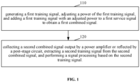
- an embodiment of the present disclosure provides a signal processing method, including following steps.
- step 110 generating a first training signal Ts, adjusting a power of the first training signal Ts, and adding a first training signal Ts with an adjusted power to a first service signal Sin to obtain a first combined signal Sout.
- the first service signal Sin includes any one of the following: a baseband service signal, a service signal before a digital predistortion processing, and a service signal after the digital predistortion processing.
- the first training signal Ts with the adjusted power may be added to the baseband service signal; or the first training signal Ts with the adjusted power may also be added to the service signal before the digital predistortion processing; or, the first training signal Ts may also be added to the service signal after the digital predistortion processing.
- generating the first training signal Ts includes: selecting a training signal with a bandwidth equal to a bandwidth corresponding to high and low frequency points of a filter in hardware configuration information from pre-stored training signals with different bandwidths; processing a selected training signal based on the hardware configuration information to obtain the first training signal Ts.
- the bandwidths of the pre-stored training signals with different bandwidths are between a minimum bandwidth and a maximum bandwidth required by the system
- a power of the pre-stored training signals is a rated power configured by the system (that is, a carrier power of each carrier in the hardware configuration information)
- a peak-to-average ratio of the pre-stored training signals is a maximum peak-to-average ratio required by the system under the rated power.
- the hardware configuration information includes: the number of the carriers, the carrier power of each of the carriers, a carrier bandwidth of each of the carriers, a frequency of a numerically controlled oscillator (NCO), a local oscillator, and the high and low frequency points of the filter.
- NCO numerically controlled oscillator
- the selected training signal is copied and frequency shifted based on the number of the carriers, so that a frequency corresponding to each of the carrier has a corresponding training signal, and a bandwidth of the training signal corresponding to each of the carriers is determined by the carrier bandwidth of the carrier in the hardware configuration information.
- a center frequency point of the first training signal Ts is determined by the local oscillator and the NCO frequency in the hardware configuration information, the NCO frequency is an offset of the local oscillator, and the total bandwidth of the first training signal is determined by the bandwidth corresponding to the high and low frequency points of the filter.
- adjusting the power of the first training signal Ts includes: adjusting the power of the first training signal Ts to be less than an average power of the first service signal Sin.
- n is a sampling sequence number of a signal window corresponding to the first service signal Sin
- N is a window length of the signal window
- S in ( i ) is an i-th first service signal value in the signal window.
- an adjustment ratio may be calculated based on a current power of the first training signal and an average power of the first service signal, that is, the adjustment ratio is a ratio of the average power of the first service signal to the current power of the first training signal. Then the first training signal with the adjusted power may be obtained by multiplying the current power of the first training signal by the adjustment ratio.
- adding the first training signal Ts with the adjusted power to the first service signal Sin to obtain the first combined signal Sout includes: determining a maximum average power of average powers of the first service signal Sin in all the signal windows within a first preset time and a peak power of a signal window corresponding to the maximum average power.
- a length of the signal window is greater than or equal to a length of the first training signal Ts, and adding the first training signal Ts with the adjusted power to a signal window meeting a preset condition in the first service signal Sin to obtain the first combined signal Sout.
- the preset condition includes: the average power of the first service signal Sin in the signal window is greater than or equal to a product of the maximum average power and ⁇ , and the peak power of the first service signal Sin in the signal window is greater than or equal to a product of the peak value of the signal window corresponding to the maximum average power and ⁇ .
- ⁇ is a power adjustment factor which may be a preset value.
- the method further includes: reducing ⁇ , and continuing to add the first training signal Ts with the adjusted power to the signal window meeting the preset condition in the first service signal Sin to obtain the first combined signal Sout, herein M is an integer greater than or equal to 1.
- the method further includes: continuing to determine a maximum average power of average powers of the first service signal Sin in all signal windows within a second preset time and a peak power of a signal window corresponding to the maximum average power, herein M is an integer greater than or equal to 1.
- the following method may be used to determine the maximum average power of the average power of the first service signal Sin in all the signal windows within the first preset time or the second preset time and the peak power of the signal window corresponding to the maximum average power: counting the average powers and the peak power of the first service signal Sin in all the signal windows in the first preset time or the second preset time; determining the maximum average power and the peak power of the signal window corresponding to the maximum average power based on the average powers and the peak power of the first service signal Sin in all the signal windows.
- the maximum average power is a maximum value of the average powers of the first service signal Sin in all the signal windows.
- the first training signal with the adjusted power may be added to the first service signal based on a certain weight or a specified orthogonal manner to ensure that a demodulation of the service signal is not affected.
- step 120 collecting a second combined signal Yout output by a power amplifier or reflected by a post-stage circuit, extracting a second training signal Ts_out from the second combined signal, and performing a signal processing based on the second training signal Ts_out.
- extracting the second training signal Ts_out from the second combined signal Yout includes: separating the second combined signal Yout into a second service signal Sout_n that does not include the second training signal and a third combined signal Wout that includes the second training signal, which may be achieved by controlling a link data collection delay in a case of separation; extracting a predetermined model based on the first service signal Sin and the second service signal Sout_n; herein the predetermined model includes a power amplifier model, or a digital predistortion model and the power amplifier model; calculating a third service signal Sout_norm in the third combined signal Wout based on the first service signal Sin and the predetermined model; calculating the second training signal Ts_out in the third combined signal Wout based on the third combined signal Wout and the third service signal Sout_norm; herein the second training signal Ts_out is a difference between the third combined signal Wout and the third service signal Sout_norm.
- the second combined signal Yout is separated into the second service signal Sout_n that does not include the second training signal and the third combined signal Wout that includes the second training signal, which may be achieved by controlling the link data collection delay in as case of separation.
- the first service signal Sin is converted into a fourth service signal before the digital predistortion processing.
- the first service signal is subjected to processing, such as the rate conversion, the shaping filtering, the peak clipping, etc., to obtain the fourth service signal before the digital predistortion processing.
- the digital predistortion model and the power amplifier model are extracted based on a part of the fourth service signal corresponding to the second service signal Sout_n and the second service signal Sout_n.
- the third service signal Sout_norm is calculated based on a part of Snorm in the fourth service signal corresponding to the third combined signal Wout, the digital predistortion model and the power amplifier model.
- the second training signal Ts_out in the third combined signal Wout is calculated based on the third combined signal Wout and the third service signal Sout_norm.
- the second training signal Ts_out is the difference between the third combined signal Wout and the third service the signal Sout_norm.
- the second combined signal Yout is separated into the second service signal Sout_n that does not include the second training signal and the third combined signal Wout that includes the second training signal, which may be achieved by controlling the link data collection delay in a case of separation.
- the first service signal Sin is converted into a fifth service signal after the digital predistortion processing.
- the first service signal is subjected to the processing, such as the rate conversion, the shaping filtering, the peak clipping, and the digital predistortion processing, to obtain the fifth service signal after the digital predistortion processing.
- the power amplifier model is extracted based on a part of the fifth service signal corresponding to the second service signal and the second service signal.
- the third service signal Sout_norm is calculated based on a part of Snorm in the fifth service signal corresponding to the third combined signal Wout and the power amplifier model.
- the second training signal Ts_out in the third combined signal Wout is calculated based on the third combined signal Wout and the third service signal Sout_norm.
- the second training signal Ts_out is the difference between the third combined signal Wout and the third service the signal Sout_norm.
- the extraction process may be performed by any one of the following modes.
- the second combined signal Yout is separated into the second service signal Sout_n that does not include the second training signal and the third combined signal Wout that includes the second training signal, which may be achieved by controlling the link data collection delay in a case of separation.
- the digital predistortion model and the power amplifier model are extracted based on a part of the first service signal Sin corresponding to the second service signal Sout_n and the second service signal Sout_n.
- the third service signal Sout_norm is calculated based on a part of Snorm corresponding to the third combined signal Wout in the first service signal Sin, the digital predistortion model and the power amplifier model.
- the second training signal Ts_out in the third combined signal Wout is calculated based on the third combined signal Wout and the third service signal Sout_norm.
- the second training signal Ts_out is the difference between the third combined signal Wout and the third service the signal Sout_norm.
- the second combined signal Yout is separated into the second service signal Sout_n that does not include the second training signal and the third combined signal Wout that includes the second training signal, which may be achieved by controlling the link data collection delay in a case of separation.
- the first service signal Sin is converted into the fifth service signal after the digital predistortion processing.
- the power amplifier model is extracted based on a part of the fifth service signal corresponding to the second service signal Sout_n and the second service signal Sout_n.
- the third service signal Sout_norm is calculated based on a part of Snorm in the fifth service signal corresponding to the third combined signal Wout and the power amplifier model.
- the second training signal Ts_out in the third combined signal Wout is calculated based on the third combined signal Wout and the third service signal Sout_norm.
- the second training signal Ts_out is the difference between the third combined signal Wout and the third service the signal Sout_norm.
- the extraction process may be performed by the following modes.
- the second combined signal Yout is separated into the second service signal Sout_n that does not include the second training signal and the third combined signal Wout that includes the second training signal, which may be achieved by controlling the link data collection delay in a case of separation.
- the power amplifier model is extracted based on a part of the first service signal Sin corresponding to the second service signal Sout_n and the second service signal Sout_n.
- the third service signal Sout_norm is calculated based on a part of Snorm in the first service signal Sin corresponding to the third combined signal Wout and the power amplifier model.
- the second training signal Ts_out in the third combined signal Wout is calculated based on the third combined signal Wout and the third service signal Sout_norm.
- the second training signal Ts_out is the difference between the third combined signal Wout and the third service the signal Sout_norm.
- the signal processing includes at least one of correcting the digital predistortion (DPD) model and performing a running state detection.
- DPD digital predistortion
- the running state detection includes at least one of a voltage standing wave ratio (VSWR) detection, a power detection, a channel performance detection (for example, an adjacent channel protection ratio (ACPR) performance) and other technologies.
- VSWR voltage standing wave ratio
- ACPR adjacent channel protection ratio
- the method further includes: converting the first training signal Ts with the adjusted power into a fourth training signal after the digital predistortion processing.
- performing the signal processing based on the second training signal Ts_out includes: performing the signal processing based on the second training signal Ts_out and the fourth training signal. For example, distortion characteristics are acquired based on the second training signal Ts_out and the fourth training signal, and the DPD model is corrected based on the distortion characteristics.
- the first training signal Ts with the adjusted power needs to be subjected to the processing, such as the rate conversion, the shaping filtering, the peak clipping, and the digital predistortion processing, to obtain the fourth training signal.
- the processing such as the rate conversion, the shaping filtering, the peak clipping, and the digital predistortion processing
- the first training signal Ts with the adjusted power When the first training signal Ts with the adjusted power is added to the service signal before the digital predistortion processing, the first training signal Ts with the adjusted power needs to be subjected to the digital predistortion processing to obtain the fourth training signal.
- performing the signal processing based on the second training signal Ts_out includes: performing the signal processing based on the second training signal Ts_out and the first training signal Ts with the adjusted power. For example, the distortion characteristics are obtained based on the second training signal Ts_out and the first training signal Ts with the adjusted power, and the DPD model is corrected based on the distortion characteristics.
- the embodiment of the present disclosure adds the training signal to the service signal to perform the signal processing (for example, a DPD model correction, a running state detection, etc.), which overcomes a limitation of sending designated signals in an idle time slot, thereby improving a stability and a performance of the system.
- the signal processing for example, a DPD model correction, a running state detection, etc.
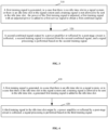
- FIG. 3 another embodiment of the present disclosure provides a signal processing method, including the following steps.
- a first training signal is generated, in a case that there is no idle time slot in a signal system; or, in a case that there is an idle time slot in the signal system, and a training signal is not allowed to be sent in the idle time slot, a power of the first training signal is adjusted, a first training signal with an adjusted power is added to a first service signal to obtain a first combined signal.
- step 110 the implementation process of generating the first training signal, adjusting the power of the first training signal, and adding the first training signal with the adjusted power to the first service signal to obtain the first combined signal is the same as that of step 110 in a previous embodiment, and will not be repeated here.
- step 320 a second combined signal output by a power amplifier or reflected by a post-stage circuit is collected, a second training signal is extracted from the second combined signal, and a signal processing is performed based on the second training signal.
- step 320 The implementation process of step 320 is the same as that of step 120 in the previous embodiment, and will not be repeated here.
- the method further includes: adding a generated first training signal to the idle time slot; collecting a third training signal in the idle time slot output by the power amplifier or reflected by the post-stage circuit; performing the signal processing based on the third training signal.
- the implementation process is the same as that of step 410 and step 420 in a following embodiment, and will not be repeated here.
- FIG. 4 another embodiment of the present disclosure provides a signal processing method, including the following steps.
- a first training signal is generated, in a case that there is an idle time slot in a signal system; or in a case that there is the idle time slot in the signal system and a training signal is allowed to be sent in the idle time slot, a generated first training signal is added to the idle time slot.
- the implementation process of generating the first training signal is the same as that of generating the first training signal in step 110 of the previous embodiment, and will not be repeated here.
- FIG. 8 is a frame structure diagram of a time division long term evolution (TD-LTE) based on an embodiment of the present disclosure.
- One frame is 10ms, including two half frames, with a total of 10 subframes, each of which is 1ms.
- a 0th subframe is a downlink subframe
- a 1st subframe is a special subframe.
- 2nd, 3rd, and 4th subframes are uplink subframes
- 5-9th subframes are downlink subframes.
- the first training signal may be sent in the idle time slot GP or in subframes of downlink service signals.
- step 420 a third training signal in the idle time slot output by a power amplifier or reflected by a post-stage circuit is collected; a signal processing is performed based on the third training signal.
- the signal processing includes at least one of correcting a digital predistortion (DPD) model and performing a running state detection.
- DPD digital predistortion
- the running status detection includes at least one of the following: a VSWR detection, a power detection, a channel performance detection (such as ACPR performance) and other technologies.
- the method further includes: converting a first training signal with an adjusted power Ts into a fourth training signal after the digital predistortion processing.
- performing the signal processing based on the third training signal includes performing the signal processing based on the third training signal and the fourth training signal. For example, distortion characteristics are acquired based on the third training signal and the fourth training signal, and the DPD model is corrected based on the distortion characteristics.
- the first training signal Ts with the adjusted power In a case that the first training signal Ts with the adjusted power is added to the baseband service signal, the first training signal Ts with the adjusted power needs to be subjected to processing, such as a rate conversion, a shaping filtering, a peak clipping, and the digital predistortion processing etc., to obtain the fourth training signal. In a case that the first training signal Ts with the adjusted power is added to the service signal before the digital predistortion processing, the first training signal Ts with the adjusted power needs to be subjected to the digital predistortion processing to obtain the fourth training signal.
- processing such as a rate conversion, a shaping filtering, a peak clipping, and the digital predistortion processing etc.
- performing the signal processing based on the third training signal includes: performing the signal processing based on the third training signal and the first training signal Ts.
- the distortion characteristics are acquired based on the third training signal and the first training signal Ts, and the DPD model is corrected based on the distortion characteristics.
- the training signal is added to the idle time slot to perform the signal processing only when there is the idle time slot in the signal system, or when there is the idle time slot in the signal system and the training signal is allowed to be sent in the idle time slot, which overcomes a limitation of sending designated signals in the idle time slot, thereby improving the stability and performance of the system.
- the embodiment of the present disclosure may send the training signal in any position of a data stream (including idle time slots and service signals).
- the power and bandwidth of the training signal are fixed, so that the traning singal has a wider bandwidth characteristics, which may make the training signal have richer power amplifier distortion characteristics or reflection characteristics, thereby improving the stability and performance of the DPD model correction and running state detection technology, suitable for all signal standard systems, such as a time division duplexing (TDD) and a frequency division duplexing (FDD).
- TDD time division duplexing
- FDD frequency division duplexing
- the signal processing method of the embodiment of the present disclosure is highly scalable, including the DPD model correction, a voltage standing wave ratio detection, the power detection, and a ACPR detection, etc., which can greatly reduce a degree of coupling with the service signals and improve an overall stability and performance indicators of a communication system.
- a signal processing device including: a signal sending module 501, configured to generate a first training signal, adjust a power of the first training signal, and add a first training signal with a adjusted power to a first service signal to obtain a first combined signal; a signal acquisition module 502, configured to collect a second combined signal output by a power amplifier or reflected by a post-stage circuit; a signal processing module 503, configured to extract a second training signal from the second combined signal, and perform a signal processing based on the second training signal.
- the signal sending module 501 is further configured to, generate the first training signal, in a case that there is no idle time slot in a signal system; or, in a case that there is an idle time slot in the signal system and a training signal is not allowed to be sent in the idle time slot, add the first training signal with the adjusted power to the first service signal to obtain the first combined signal.
- the signal sending module 501 is further configured to add a generated first training signal to the idle time slot, in a case that there is the idle time slot in the signal system; or in a case that there is the idle time slot in the signal system and the training signal is allowed to be sent in the idle time slot.
- the signal acquisition module 502 is also configured to collect a third training signal in the idle time slot output by the power amplifier or reflected by the post-stage circuit.
- the signal processing module 503 is also configured to perform the signal processing based on the third training signal.
- the signal sending module 501 is configured to adjust the power of the first training signal in the following manner: adjusting the power of the first training signal to be less than an average power of the first service signal.
- the signal sending module 501 is configured to generate the first training signal in the following manner: selecting a training signal with a bandwidth equal to a bandwidth corresponding to high and low frequency points of a filter in hardware configuration information from pre-stored training signals with different bandwidths; and processing a selected training signal based on the hardware configuration information to obtain the first training signal.
- the signal sending module 501 is configured to add the first training signal with the adjusted power to the first service signal to obtain the first combined signal in the following manner: determining a maximum average power of the first service signal in all signal windows within a first preset time and a peak power of a signal window corresponding to the maximum average power; herein a length of the signal window is greater than or equal to a length of the first training signal; adding the first training signal with the adjusted power to a signal window meeting a preset condition in the first service signal to obtain the first combined signal.
- the preset condition includes: an average power of the first service signal in the signal window is greater than or equal to a product of the maximum average power and ⁇ , and the peak power of the first service signal in the signal window is greater than or equal to a product of the peak value of the signal window corresponding to the maximum average power and ⁇ .
- the signal sending module 501 is further configured to: reduce ⁇ in a case that ⁇ is greater than a preset threshold and the signal window meeting the preset condition is unable to be found for M consecutive times in the first service signal, and continue to add the first training signal with the adjusted power to the signal window meeting the preset condition in the first service signal to obtain the first combined signal; herein M is an integer greater than or equal to 1.
- the signal sending module 501 is further configured to continue to determine a maximum average power of the first service signal in all the signal windows within a second preset time and a peak power of a signal window corresponding to the maximum average power, in a case that ⁇ is less than or equal to the preset threshold and the signal window meeting the preset condition in the first service signal is unable to be found for M consecutive times, herein M is an integer greater than or equal to 1.
- the first service signal includes any one of the following: a baseband service signal, a service signal before a digital predistortion processing, and a service signal after the digital predistortion processing.
- the signal processing module 503 is further configured to: extract the second training signal from the second combined signal, convert the first training signal with the adjusted power into a fourth training signal after the digital predistortion processing in a case that the first service signal is the baseband service signal or the service signal before the digital predistortion processing, perform the signal processing based on the second training signal and the fourth training signal.
- the signal processing module 503 is configured to extract the second training signal from the second combined signal, and perform the signal processing based on the second training signal and the first training signal with the adjusted power in a case that the first service signal is the baseband service signal.
- the signal processing module 503 is configured to extract the second training signal from the second combined signal in the following manner: separating the second combined signal into a second service signal that does not include the second training signal and a third combined signal that includes the second training signal; extracting a predetermined model based on the first service signal and the second service signal; herein the predetermined model includes a power amplifier model, or a digital predistortion model and a power amplifier model; calculating a third service signal in the third combined signal based on the first service signal and the predetermined model; and calculating the second training signal in the third combined signal based on the third combined signal and the third service signal.
- the signal processing module 503 is further configured to: convert the first service signal into a fourth service signal before the digital predistortion processing or a fifth service signal after the digital predistortion processing in a case that the first service signal is the baseband service signal or the service signal before the digital predistortion processing; extract the digital predistortion model and the power amplifier model based on a part of the fourth service signal corresponding to the second service signal and the second service signal; or, extract the power amplifier model from a part of the fifth service signal corresponding to the second service signal and the second service signal; calculate the third service signal based on a part of the fourth service signal corresponding to the third combined signal, the digital predistortion model and the power amplifier model; alternatively, calculate the third service signal based on a part of the fifth service signal corresponding to the third combined signal and the power amplifier model.
- the signal processing module 503 is configured to: extract the digital predistortion model and the power amplifier model based on a part of the first service signal corresponding to the second service signal and the second service signal in a case that the first service signal is the service signal before the predistortion processing; calculate the third service signal based on a part of the first service signal corresponding to the third combined signal, the digital predistortion model and the power amplifier model.
- the signal processing module 503 is configured to: extract the power amplifier model based on the part of the first service signal corresponding to the second service signal and the second service signal in a case that the first service signal is the service signal after the predistortion processing; calculate the third service signal based on the part of the first service signal corresponding to the third combined signal and the power amplifier model.
- the signal processing includes at least one of correcting the digital predistortion model and performing a running state detection.
- FIG. 6 is a schematic diagram of a signal processing device according to an embodiment of the present disclosure.
- the signal processing device adds the training signal to the service signal, and outputs the service signal after passing through a predistortion module and a power amplifier.
- the training signal is extracted from a signal output by the power amplifier.
- the training signal contains power amplifier distortion characteristics.
- the signal processing device can help a system modify a digital pre-distortion model and improve stability and performance of the DPD in different service signal scenarios.
- the signal processing device includes: a predistortion module, a power amplifier module (i.e., a power amplifier), a signal selection module, and a predistortion correcting module.
- a predistortion module i.e., a power amplifier
- a power amplifier module i.e., a power amplifier
- a signal selection module i.e., a signal selection module
- a predistortion correcting module i.e., a predistortion correcting module.
- the predistortion module is configured to correct a nonlinearity of the power amplifier to ensure a linear output of the power amplifier.
- the power amplifier is configured to mainly amplify a power of a radio frequency signal, and finally make the radio frequency signal transmitted into a space in a form of electromagnetic waves through the filter and an antenna.
- the signal selection module mainly includes a switch (optional, including a digital switch and/or a radio frequency switch), a circulator (optional) and a coupler.
- the circulator is configured to isolate transmitted signals and reflected signals, and use the coupler to couple part of the transmitted or reflected signals into an analog-to-digital converter (ADC) module for a collection.
- ADC analog-to-digital converter
- the system may set up and control the digital and radio frequency switches based on the specific requirements of each function, so as to ensure the normal and orderly operation of the entire system.
- the pre-distortion correction module is configured to use a first training signal without distortion and a second training signal coupled back to the power amplifier port to extract the power amplifier distortion characteristics of the training signal for a pre-distortion model correction.
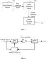
- FIG. 7 is another schematic diagram of a signal processing device according to an embodiment of the present disclosure.
- the signal processing device adds a training signal to a service signal, and then outputs the service signal after passing through a predistortion module and a power amplifier.
- the training signal is extracted from a signal output by the power amplifier or a signal reflected by a post-stage circuit.
- the training signal includes power amplifier distortion, reflection and other characteristics.
- the signal processing device can help a system: (1) modify a digital predistortion model to improve stability and performance of the DPD in different service signal scenarios; (2) improve stability of a standing wave ratio detection in the different service signal scenarios; (3) improve stability of a system power detection in multiple service scenarios; (4) perform an ACPR online detection, etc.
- the signal processing device mainly includes eight modules: a training signal generation module, a training signal detection module, a training signal processing module, a power detection module, a predistortion module, a radio frequency module, a power amplifier module (i.e. power amplifier), a signal selection module, a digital to analog converter (DAC) module and an analog to digital converter (ADC) module.
- the power detection module is configured to count an average power and a peak power of a current digital signal in real time, and send the average power and peak power of the current digital signal to the training signal generation module to determine relevant parameters of a first training signal, such as a power, a peak-to-average ratio, etc.
- the training signal generating module is configured to generate a first training signal Ts, adjust a power of the first training signal Ts, and determine a position that a first training signal Ts with an adjusted power added to a first service signal Sin.
- the predistortion module is configured to correct a nonlinearity of the power amplifier to ensure a linear output of the power amplifier.
- the DAC module is configured to convert digital signals into analog signals.
- the ADC module is configured to convert analog signals into digital signals.
- the radio frequency module is configured to perform a spectrum shifting and a small signal amplification for the analog signals.
- the power amplifier is configured to mainly amplify a power of a radio frequency signal, and finally make the radio frequency signal transmitted into a space in a form of electromagnetic waves through an filter and an antenna (that is, the post-stage circuit).
- the signal selection module mainly includes a switch (optional, including a digital switch and/or a radio frequency switch), a circulator (optional) and a coupler.
- the circulator is configured to isolate transmitted signals and reflected signals, and uses the coupler to couple part of the transmitted signals and reflected signals into the ADC module for collection.
- the system may set up and control the digital and radio frequency switches based on the specific requirements of each function, so as to ensure the normal and orderly operation of the entire system.
- the training signal detection module is configured to, in a case that the first training signal is added to the first service signal for sending, establish a service signal power amplifier model based on characteristics of the first training signal sent in advance and the first service signal at a position of the first training signal, and extract a second training signal from a coupling signal of a power amplifier output port or a reflection port.
- the training signal processing module is configured to use a distortion-free first training signal and the second training signal coupled back to the power amplifier port or the reflection port to extract power amplifier distortion characteristics or reflection characteristics of the training signal, and set them as pre-distortion model correction and standing wave ratio calculation correction, respectively.
- Another embodiment of the present disclosure provides a signal processing device including a processor and a computer-readable storage medium.
- the computer-readable storage medium stores an instruction that, when executed by the processor, allows the processor to perform anyone of the signal processing methods.
- Another embodiment of the present disclosure provides a computer-readable storage medium storing a computer program that, when executed by a processor, allows the processor to perform the steps of anyone of the signal processing methods.
- a person of ordinary skill in the art may understand that all or some of the steps, system, functional modules/units of the device in the methods disclosed above may be implemented as software, firmware, hardware, and appropriate combinations thereof.
- the division between functional modules/units mentioned in the above description does not necessarily correspond to the division of physical components.
- a physical component may have multiple functions, or a function or step may be performed by several physical components cooperatively.
- Some or all of the components may be implemented as software executed by a processor (such as a digital signal processor or a microprocessor), or as hardware, or as an integrated circuit (such as an application specific integrated circuit).
- Such software may be distributed on a computer-readable medium, and the computer-readable medium may include a computer storage medium (or a non-transitory medium) and a communication medium (or a transitory medium).
- the term computer storage medium includes volatile and non-volatile, removable and non-removable medium implemented in any method or technology for storing information (such as computer-readable instructions, data structures, program modules, or other data).
- Computer storage medium include but are not limited to a random access memory (RAM), a read-only memory (ROM), an electrically erasable programmable read-only memory (EEPROM), a flash memory or other memory technologies, a compact disc read-only memory (CD-ROM), a digital video disc (DVD) or other optical disk storage, a magnetic cassette, a magnetic tape, a magnetic disk storage or other magnetic storage devices, or any other medium used to store desired information and that may be accessed by a computer.
- communication medium usually contain a computer-readable instruction, a data structure, a program module, or other data in a modulated data signal such as a carrier wave or other transmission mechanisms, and may include any information delivery medium.
Landscapes
- Engineering & Computer Science (AREA)
- Power Engineering (AREA)
- Physics & Mathematics (AREA)
- Computer Networks & Wireless Communication (AREA)
- Signal Processing (AREA)
- Nonlinear Science (AREA)
- Theoretical Computer Science (AREA)
- Spectroscopy & Molecular Physics (AREA)
- Amplifiers (AREA)
- Transmitters (AREA)
Claims (14)
- Signalverarbeitungsverfahren, umfassend:Erzeugen eines ersten Trainingssignals, Anpassen einer Leistung des ersten Trainingssignals und Hinzufügen eines ersten Trainingssignals mit einer angepassten Leistung zu einem ersten Dienstsignal, um ein erstes kombiniertes Signal zu erhalten; undSammeln eines zweiten kombinierten Signals, das von einem Leistungsverstärker ausgegeben oder von einer Nachstufenschaltung reflektiert wird, in die das erste kombinierte Signal eingegeben wird, Extrahieren eines zweiten Trainingssignals aus dem zweiten kombinierten Signal und Durchführen einer Signalverarbeitung basierend auf dem zweiten Trainingssignal, wobei die Signalverarbeitung das Korrigieren eines digitalen Vorverzerrungs-DPD-Modells umfasst, dadurch gekennzeichnet, dass:
das Extrahieren des zweiten Trainingssignals aus dem zweiten kombinierten Signal umfasst:Auftrennen des zweiten kombinierten Signals in ein zweites Dienstsignal, das das zweite Trainingssignal nicht einschließt, und ein drittes kombiniertes Signal, das das zweite Trainingssignal einschließt;Extrahieren eines vorbestimmten Modells basierend auf dem ersten Dienstsignal und dem zweiten Dienstsignal; wobei das vorbestimmte Modell ein Leistungsverstärkermodell oder ein digitales Vorverzerrungsmodell und das Leistungsverstärkermodell umfasst;Berechnen eines dritten Dienstsignals im dritten kombinierten Signal basierend auf dem ersten Dienstsignal und dem vorbestimmten Modell; undBerechnen des zweiten Trainingssignals im dritten kombinierten Signal basierend auf dem dritten kombinierten Signal und dem dritten Dienstsignal. - Verfahren nach Anspruch 1, ferner umfassend:als Reaktion darauf, dass in einem Signalsystem kein freier Zeitschlitz vorhanden ist; oder als Reaktion darauf, dass im Signalsystem ein freier Zeitschlitz vorhanden ist und in dem freien Zeitschlitz kein Trainingssignal gesendet werden darf, Fortsetzen der Anpassung der Leistung des ersten Trainingssignals; undwobei das Anpassen der Leistung des ersten Trainingssignals das Anpassen der Leistung des ersten Trainingssignals derart umfasst, dass sie geringer ist als eine durchschnittliche Leistung des ersten Dienstsignals.
- Verfahren nach Anspruch 1 als Reaktion auf das Vorhandensein eines freien Zeitschlitzes in einem Signalsystem; oder
als Reaktion darauf, dass ein freier Zeitschlitz im Signalsystem vorhanden ist und das Senden eines Trainingssignals in dem freien Zeitschlitz zulässig ist, das Verfahren ferner umfasst:Hinzufügen des ersten generierten Trainingssignals zum freien Zeitschlitz;Sammeln eines dritten Trainingssignals im freien Zeitschlitz, das vom Leistungsverstärker ausgegeben oder von der Nachstufenschaltung reflektiert wird; undDurchführen der Signalverarbeitung basierend auf dem dritten Trainingssignal; undwobei das Generieren des ersten Trainingssignals umfasst:Auswählen eines Trainingssignals mit einer Bandbreite gleich einer Bandbreite, die einem Hoch- und Niederfrequenzpunkt eines Filters in den Hardwarekonfigurationsinformationen aus vorab gespeicherten Trainingssignalen unterschiedlicher Bandbreiten entspricht;Verarbeiten eines ausgewählten Trainingssignals basierend auf den Hardwarekonfigurationsinformationen, um das erste Trainingssignal zu erhalten. - Verfahren nach Anspruch 1, wobei das Hinzufügen des ersten Trainingssignals mit der angepassten Leistung zum ersten Dienstsignal zum Erhalten des ersten kombinierten Signals umfasst:Bestimmen einer maximalen Durchschnittsleistung der Durchschnittsleistungen des ersten Dienstsignals in allen Signalfenstern innerhalb einer ersten voreingestellten Zeit und einer Spitzenleistung eines Signalfensters, die der maximalen Durchschnittsleistung entspricht; wobei eine Länge des Signalfensters größer als oder gleich einer Länge des ersten Trainingssignals ist;Hinzufügen des ersten Trainingssignals mit der angepassten Leistung zu einem Signalfenster, das eine voreingestellte Bedingung im ersten Dienstsignal erfüllt, um das erste kombinierte Signal zu erhalten; wobei die voreingestellte Bedingung umfasst:die durchschnittliche Leistung des ersten Dienstsignals im Signalfenster ist größer als oder gleich ein Produkt aus der maximalen durchschnittlichen Leistung und β unddie Spitzenleistung des ersten Dienstsignals im Signalfenster ist größer als oder gleich ein Produkt aus dem Spitzenwert des Signalfensters, das der maximalen Durchschnittsleistung entspricht, und β.
- Verfahren nach Anspruch 4, wenn β größer als ein voreingestellter Schwellenwert ist und das Signalfenster, das die voreingestellte Bedingung im ersten Dienstsignal erfüllt, M-mal hintereinander nicht gefunden werden kann, wobei das Verfahren ferner umfasst:Reduzieren von β und Fortsetzen des Hinzufügens des ersten Trainingssignals mit der angepassten Leistung zu dem Signalfenster, das die voreingestellte Bedingung im ersten Dienstsignal erfüllt, um das erste kombinierte Signal zu erhalten;wobei M eine Ganzzahl größer als oder gleich 1 ist; oderwenn β kleiner als oder gleich ein voreingestellter Schwellenwert ist und das Signalfenster, das die voreingestellte Bedingung im ersten Dienstsignal erfüllt, M-mal hintereinander nicht gefunden werden kann, das Verfahren ferner umfasst:Fortsetzen des Bestimmens einer maximalen Durchschnittsleistung der Durchschnittsleistungen des ersten Dienstsignals in allen Signalfenstern innerhalb einer zweiten voreingestellten Zeit und einer Spitzenleistung eines Signalfensters, die der maximalen Durchschnittsleistung entspricht;wobei M eine Ganzzahl größer als oder gleich 1 ist.
- Verfahren nach Anspruch 1, wobei das erste Dienstsignal eines von einem Basisband-Dienstsignal, einem Dienstsignal vor einer digitalen Vorverzerrungsverarbeitung oder einem Dienstsignal nach der digitalen Vorverzerrungsverarbeitung umfasst; und
die Signalverarbeitung ferner die Durchführung einer Laufzustandserkennung umfasst. - Verfahren nach Anspruch 6, wenn das erste Dienstsignal das Basisband-Dienstsignal oder das Dienstsignal vor der digitalen Vorverzerrungsverarbeitung ist, vor dem Durchführen der Signalverarbeitung basierend auf dem zweiten Trainingssignal das Verfahren ferner umfasst:Umwandeln des ersten Trainingssignals mit der angepassten Leistung in ein viertes Trainingssignal nach der digitalen Vorverzerrungsverarbeitung; unddas Durchführen der Signalverarbeitung basierend auf dem zweiten Trainingssignal umfasst:
das Durchführen der Signalverarbeitung basierend auf dem zweiten Trainingssignal und dem vierten Trainingssignal. - Verfahren nach Anspruch 6, wobei, wenn das erste Dienstsignal ein Basisband-Dienstsignal ist, das Durchführen der Signalverarbeitung basierend auf dem zweiten Trainingssignal umfasst:
Durchführen der Signalverarbeitung basierend auf dem zweiten Trainingssignal und dem ersten Trainingssignal mit der angepassten Leistung. - Verfahren nach Anspruch 1, wenn das erste Dienstsignal ein Basisband-Dienstsignal oder ein Dienstsignal vor einer digitalen Vorverzerrungsverarbeitung ist, vor dem Extrahieren des vorbestimmten Modells basierend auf dem ersten Dienstsignal und dem zweiten Dienstsignal das Verfahren ferner umfasst:Umwandeln des ersten Dienstsignals in ein viertes Dienstsignal vor der digitalen Vorverzerrungsverarbeitung oder in ein fünftes Dienstsignal nach der digitalen Vorverzerrungsverarbeitung; unddas Extrahieren eines vorbestimmten Modells basierend auf dem ersten Dienstsignal und dem zweiten Dienstsignal umfasst:Extrahieren des digitalen Vorverzerrungsmodells und des Leistungsverstärkermodells basierend auf einem Teil des vierten Dienstsignals, der dem zweiten Dienstsignal und dem zweiten Dienstsignal entspricht; oderExtrahieren des Leistungsverstärkermodells basierend auf einem Teil des fünften Dienstsignals, der dem zweiten Dienstsignal und dem zweiten Dienstsignal entspricht; unddas Berechnen des dritten Dienstsignals im dritten kombinierten Signal basierend auf dem ersten Dienstsignal und einem vorbestimmten Modell umfasst:Berechnen des dritten Dienstsignals basierend auf einem Teil des vierten Dienstsignals, der dem dritten kombinierten Signal, dem digitalen Vorverzerrungsmodell und dem Leistungsverstärkermodell entspricht; oderBerechnen des dritten Dienstsignals basierend auf einem Teil des fünften Dienstsignals, der dem dritten kombinierten Signal und dem Leistungsverstärkermodell entspricht.
- Verfahren nach Anspruch 1, wobei, wenn das erste Dienstsignal ein Dienstsignal vor einer Vorverzerrungsverarbeitung ist, das Extrahieren des vorbestimmten Modells gemäß dem ersten Dienstsignal und dem zweiten Dienstsignal umfasst:
Extrahieren des digitalen Vorverzerrungsmodells und des Leistungsverstärkermodells basierend auf einem Teil des ersten Dienstsignals, der dem zweiten Dienstsignal und dem zweiten Dienstsignal entspricht; das Berechnen des dritten Dienstsignals im dritten kombinierten Signal basierend auf dem ersten Dienstsignal und dem vorbestimmten Modell umfasst:
Berechnen des dritten Dienstsignals basierend auf einem Teil des ersten Dienstsignals, der dem dritten kombinierten Signal, dem digitalen Vorverzerrungsmodell und dem Leistungsverstärkermodell entspricht. - Verfahren nach Anspruch 1, wobei, wenn das erste Dienstsignal ein Dienstsignal nach einer Vorverzerrungsverarbeitung ist, das Extrahieren des vorbestimmten Modells basierend auf dem ersten Dienstsignal und dem zweiten Dienstsignal umfasst:Extrahieren des Leistungsverstärkermodells basierend auf einem Teil des ersten Dienstsignals, der dem zweiten Dienstsignal und dem zweiten Dienstsignal entspricht; unddas Berechnen des dritten Dienstsignals im dritten kombinierten Signal basierend auf dem ersten Dienstsignal und dem vorbestimmten Modell umfasst:
Berechnen des dritten Dienstsignals basierend auf einem Teil des ersten Dienstsignals, der dem dritten kombinierten Signal und dem Leistungsverstärkermodell entspricht. - Signalverarbeitungsvorrichtung, umfassend:ein Signalsendemodul, konfiguriert zum Erzeugen eines ersten Trainingssignals, Anpassen einer Leistung des ersten Trainingssignals und Hinzufügen eines ersten Trainingssignals mit einer angepassten Leistung zu einem ersten Dienstsignal, um ein erstes kombiniertes Signal zu erhalten;ein Signalerfassungsmodul, konfiguriert zum Sammeln eines zweiten kombinierten Signals, das von einem Leistungsverstärker ausgegeben oder von einer Nachstufenschaltung reflektiert wird, in die das erste kombinierte Signal eingegeben wird; undein Signalverarbeitungsmodul, konfiguriert zum Extrahieren eines zweiten Trainingssignals aus dem zweiten kombinierten Signal und Durchführen einer Signalverarbeitung basierend auf dem zweiten Trainingssignal, wobei die Signalverarbeitung das Korrigieren eines digitalen Vorverzerrungs-DPD-Modells umfasst,dadurch gekennzeichnet, dass:
das Signalverarbeitungsmodul ferner konfiguriert ist zum:
Extrahieren des zweiten Trainingssignals aus dem zweiten kombinierten Signal, das umfasst:Auftrennen des zweiten kombinierten Signals in ein zweites Dienstsignal, das das zweite Trainingssignal nicht einschließt, und ein drittes kombiniertes Signal, das das zweite Trainingssignal einschließt;Extrahieren eines vorbestimmten Modells basierend auf dem ersten Dienstsignal und dem zweiten Dienstsignal;wobei das vorbestimmte Modell ein Leistungsverstärkermodell oder ein digitales Vorverzerrungsmodell und das Leistungsverstärkermodell umfasst;Berechnen eines dritten Dienstsignals im dritten kombinierten Signal basierend auf dem ersten Dienstsignal und dem vorbestimmten Modell; undBerechnen des zweiten Trainingssignals im dritten kombinierten Signal basierend auf dem dritten kombinierten Signal und dem dritten Dienstsignal. - Signalverarbeitungsvorrichtung, umfassend einen Prozessor und ein computerlesbares Speicherungsmedium umfasst, wobei das computerlesbare Speicherungsmedium eine Anweisung speichert, die, wenn sie durch den Prozessor ausgeführt werden, bewirken,
dass der Prozessor das Signalverarbeitungsverfahren nach einem der Ansprüche 1 bis 11 durchführt. - Computerlesbares Speicherungsmedium, auf dem ein Computerprogramm gespeichert ist, das, wenn es durch einen Prozessor ausgeführt wird, den Prozessor veranlasst zum
Durchführen des Signalverarbeitungsverfahrens nach einem der Ansprüche 1 bis 11.
Applications Claiming Priority (2)
| Application Number | Priority Date | Filing Date | Title |
|---|---|---|---|
| CN201910450101.1A CN112019221B (zh) | 2019-05-28 | 2019-05-28 | 一种信号处理方法、装置和存储介质 |
| PCT/CN2020/093040 WO2020239043A1 (zh) | 2019-05-28 | 2020-05-28 | 信号处理方法、装置和存储介质 |
Publications (3)
| Publication Number | Publication Date |
|---|---|
| EP3962008A1 EP3962008A1 (de) | 2022-03-02 |
| EP3962008A4 EP3962008A4 (de) | 2022-07-13 |
| EP3962008B1 true EP3962008B1 (de) | 2024-10-16 |
Family
ID=73500475
Family Applications (1)
| Application Number | Title | Priority Date | Filing Date |
|---|---|---|---|
| EP20814250.5A Active EP3962008B1 (de) | 2019-05-28 | 2020-05-28 | Verfahren und vorrichtung zur signalverarbeitung und speichermedium |
Country Status (4)
| Country | Link |
|---|---|
| EP (1) | EP3962008B1 (de) |
| CN (1) | CN112019221B (de) |
| ES (1) | ES2997985T3 (de) |
| WO (1) | WO2020239043A1 (de) |
Families Citing this family (4)
| Publication number | Priority date | Publication date | Assignee | Title |
|---|---|---|---|---|
| CN113242196B (zh) * | 2021-03-23 | 2022-11-18 | 海能达通信股份有限公司 | 数字预失真方法、系统及通信设备 |
| US12206441B2 (en) * | 2022-03-31 | 2025-01-21 | Dell Products L.P. | Detection and cancellation of unwanted signals in a wireless communication radio unit |
| US12224782B2 (en) | 2022-04-14 | 2025-02-11 | Dell Products L.P. | Detection, cancellation, and evaluation of signals in a wireless communication radio unit |
| US12003280B2 (en) | 2022-04-22 | 2024-06-04 | Dell Products L.P. | Analog domain loopback modes |
Family Cites Families (8)
| Publication number | Priority date | Publication date | Assignee | Title |
|---|---|---|---|---|
| US7170344B2 (en) * | 2004-02-03 | 2007-01-30 | Ntt Docomo, Inc. | Multi-band predistorter using power series representation |
| CN101483623A (zh) * | 2008-12-17 | 2009-07-15 | 成都凯腾四方数字广播电视设备有限公司 | 一种基带自适应数字预失真功放校正方法及系统 |
| CN102082752B (zh) * | 2010-02-25 | 2014-03-19 | 电信科学技术研究院 | 一种数字预失真处理方法及设备 |
| KR101440121B1 (ko) * | 2010-07-28 | 2014-09-12 | 한국전자통신연구원 | 왜곡 보상 장치, 신호 송신 장치 및 그 방법 |
| CN102412855B (zh) * | 2010-09-20 | 2015-03-25 | 大唐移动通信设备有限公司 | 阻抗匹配情况确定方法和设备 |
| CN102763389B (zh) * | 2011-08-19 | 2015-08-26 | 华为技术有限公司 | 信号序列处理方法和基站 |
| US20170303118A1 (en) * | 2016-04-14 | 2017-10-19 | Qualcomm Incorporated | Managing digital pre-distortion training in radio transceivers |
| CN208675192U (zh) * | 2018-08-16 | 2019-03-29 | 奥维飞越通信有限公司 | 一种宽带预失真功率放大器装置 |
-
2019
- 2019-05-28 CN CN201910450101.1A patent/CN112019221B/zh active Active
-
2020
- 2020-05-28 EP EP20814250.5A patent/EP3962008B1/de active Active
- 2020-05-28 WO PCT/CN2020/093040 patent/WO2020239043A1/zh not_active Ceased
- 2020-05-28 ES ES20814250T patent/ES2997985T3/es active Active
Also Published As
| Publication number | Publication date |
|---|---|
| ES2997985T3 (en) | 2025-02-18 |
| EP3962008A1 (de) | 2022-03-02 |
| CN112019221B (zh) | 2021-11-02 |
| CN112019221A (zh) | 2020-12-01 |
| EP3962008A4 (de) | 2022-07-13 |
| WO2020239043A1 (zh) | 2020-12-03 |
Similar Documents
| Publication | Publication Date | Title |
|---|---|---|
| EP3962008B1 (de) | Verfahren und vorrichtung zur signalverarbeitung und speichermedium | |
| EP2754239B1 (de) | Linearisierung für einen einzelnen leistungsverstärker bei einem mehrfrequenzbandsender | |
| US9252718B2 (en) | Low complexity digital predistortion for concurrent multi-band transmitters | |
| US9071207B2 (en) | Predistortion of concurrent multi-band signal to compensate for PA non-linearity | |
| CN101056288B (zh) | 预失真模型装置和信号的预失真处理装置、系统及方法 | |
| CN100566312C (zh) | 用于线性化带有不对称特性的功率放大器的数字预失真 | |
| EP3089414B1 (de) | Verfahren zur erstellung digitaler vorentzerrungsparameter und vorentzerrungssystem | |
| US20160285485A1 (en) | Method and apparatus for multiband predistortion using time-shared adaptation loop | |
| US8428525B2 (en) | Predistorter for a multi-antenna transmitter | |
| CN101330481B (zh) | 预失真模型装置和信号的预失真处理装置、系统及方法 | |
| US20230361722A1 (en) | Dpd apparatus and method applicable to 5g broadband mimo system | |
| EP3208938B1 (de) | Vorrichtung und verfahren zur vorverzerrungsverarbeitung | |
| CN101355536B (zh) | 对基带信号进行预失真处理的装置及方法 | |
| CN103427868A (zh) | 一种射频信号的控制方法和设备 | |
| EP1652294B1 (de) | Sender mit kartesischer schleife und verfahren zur einstellung eines ausgangspegels eines solchen senders | |
| US6498529B1 (en) | Method and apparatus for calculating the predistortion function from a power amplifier | |
| JP2007522738A (ja) | エンベロープ除去および回復による信号増幅方法およびシステム | |
| JP2008294518A (ja) | 送信装置 | |
| CN106330802A (zh) | 一种移动通信系统的数字预失真处理装置及方法 | |
| CN105900333B (zh) | 射频功率放大系统、射频功率放大方法、发射机及基站 | |
| US8525592B2 (en) | Power amplification device, transmitter, and power amplification control method | |
| CN201947373U (zh) | 一种高效率数字电视发射装置 | |
| US20220360291A1 (en) | Efficient amplifer operation | |
| US20250184207A1 (en) | Digital predistortion method and apparatus | |
| US11411587B2 (en) | Signal processing method and system |
Legal Events
| Date | Code | Title | Description |
|---|---|---|---|
| STAA | Information on the status of an ep patent application or granted ep patent |
Free format text: STATUS: THE INTERNATIONAL PUBLICATION HAS BEEN MADE |
|
| PUAI | Public reference made under article 153(3) epc to a published international application that has entered the european phase |
Free format text: ORIGINAL CODE: 0009012 |
|
| STAA | Information on the status of an ep patent application or granted ep patent |
Free format text: STATUS: REQUEST FOR EXAMINATION WAS MADE |
|
| 17P | Request for examination filed |
Effective date: 20211126 |
|
| AK | Designated contracting states |
Kind code of ref document: A1 Designated state(s): AL AT BE BG CH CY CZ DE DK EE ES FI FR GB GR HR HU IE IS IT LI LT LU LV MC MK MT NL NO PL PT RO RS SE SI SK SM TR |
|
| A4 | Supplementary search report drawn up and despatched |
Effective date: 20220613 |
|
| RIC1 | Information provided on ipc code assigned before grant |
Ipc: H04L 25/49 20060101AFI20220608BHEP |
|
| DAV | Request for validation of the european patent (deleted) | ||
| DAX | Request for extension of the european patent (deleted) | ||
| REG | Reference to a national code |
Ref country code: DE Ref legal event code: R079 Free format text: PREVIOUS MAIN CLASS: H04L0025490000 Ipc: H04B0001040000 Ref country code: DE Ref legal event code: R079 Ref document number: 602020039638 Country of ref document: DE Free format text: PREVIOUS MAIN CLASS: H04L0025490000 Ipc: H04B0001040000 |
|
| GRAP | Despatch of communication of intention to grant a patent |
Free format text: ORIGINAL CODE: EPIDOSNIGR1 |
|
| STAA | Information on the status of an ep patent application or granted ep patent |
Free format text: STATUS: GRANT OF PATENT IS INTENDED |
|
| RIC1 | Information provided on ipc code assigned before grant |
Ipc: H04L 25/03 20060101ALI20240614BHEP Ipc: H03F 3/24 20060101ALI20240614BHEP Ipc: H04B 1/04 20060101AFI20240614BHEP |
|
| INTG | Intention to grant announced |
Effective date: 20240717 |
|
| GRAS | Grant fee paid |
Free format text: ORIGINAL CODE: EPIDOSNIGR3 |
|
| GRAA | (expected) grant |
Free format text: ORIGINAL CODE: 0009210 |
|
| STAA | Information on the status of an ep patent application or granted ep patent |
Free format text: STATUS: THE PATENT HAS BEEN GRANTED |
|
| AK | Designated contracting states |
Kind code of ref document: B1 Designated state(s): AL AT BE BG CH CY CZ DE DK EE ES FI FR GB GR HR HU IE IS IT LI LT LU LV MC MK MT NL NO PL PT RO RS SE SI SK SM TR |
|
| REG | Reference to a national code |
Ref country code: GB Ref legal event code: FG4D |
|
| REG | Reference to a national code |
Ref country code: CH Ref legal event code: EP |
|
| REG | Reference to a national code |
Ref country code: IE Ref legal event code: FG4D |
|
| REG | Reference to a national code |
Ref country code: DE Ref legal event code: R096 Ref document number: 602020039638 Country of ref document: DE |
|
| REG | Reference to a national code |
Ref country code: LT Ref legal event code: MG9D |
|
| REG | Reference to a national code |
Ref country code: ES Ref legal event code: FG2A Ref document number: 2997985 Country of ref document: ES Kind code of ref document: T3 Effective date: 20250218 |
|
| REG | Reference to a national code |
Ref country code: NL Ref legal event code: MP Effective date: 20241016 |
|
| REG | Reference to a national code |
Ref country code: AT Ref legal event code: MK05 Ref document number: 1733765 Country of ref document: AT Kind code of ref document: T Effective date: 20241016 |
|
| PG25 | Lapsed in a contracting state [announced via postgrant information from national office to epo] |
Ref country code: NL Free format text: LAPSE BECAUSE OF FAILURE TO SUBMIT A TRANSLATION OF THE DESCRIPTION OR TO PAY THE FEE WITHIN THE PRESCRIBED TIME-LIMIT Effective date: 20241016 |
|
| PG25 | Lapsed in a contracting state [announced via postgrant information from national office to epo] |
Ref country code: NL Free format text: LAPSE BECAUSE OF FAILURE TO SUBMIT A TRANSLATION OF THE DESCRIPTION OR TO PAY THE FEE WITHIN THE PRESCRIBED TIME-LIMIT Effective date: 20241016 |
|
| PG25 | Lapsed in a contracting state [announced via postgrant information from national office to epo] |
Ref country code: HR Free format text: LAPSE BECAUSE OF FAILURE TO SUBMIT A TRANSLATION OF THE DESCRIPTION OR TO PAY THE FEE WITHIN THE PRESCRIBED TIME-LIMIT Effective date: 20241016 Ref country code: PT Free format text: LAPSE BECAUSE OF FAILURE TO SUBMIT A TRANSLATION OF THE DESCRIPTION OR TO PAY THE FEE WITHIN THE PRESCRIBED TIME-LIMIT Effective date: 20250217 Ref country code: IS Free format text: LAPSE BECAUSE OF FAILURE TO SUBMIT A TRANSLATION OF THE DESCRIPTION OR TO PAY THE FEE WITHIN THE PRESCRIBED TIME-LIMIT Effective date: 20250216 |
|
| PG25 | Lapsed in a contracting state [announced via postgrant information from national office to epo] |
Ref country code: FI Free format text: LAPSE BECAUSE OF FAILURE TO SUBMIT A TRANSLATION OF THE DESCRIPTION OR TO PAY THE FEE WITHIN THE PRESCRIBED TIME-LIMIT Effective date: 20241016 |
|
| PG25 | Lapsed in a contracting state [announced via postgrant information from national office to epo] |
Ref country code: BG Free format text: LAPSE BECAUSE OF FAILURE TO SUBMIT A TRANSLATION OF THE DESCRIPTION OR TO PAY THE FEE WITHIN THE PRESCRIBED TIME-LIMIT Effective date: 20241016 |
|
| PG25 | Lapsed in a contracting state [announced via postgrant information from national office to epo] |
Ref country code: NO Free format text: LAPSE BECAUSE OF FAILURE TO SUBMIT A TRANSLATION OF THE DESCRIPTION OR TO PAY THE FEE WITHIN THE PRESCRIBED TIME-LIMIT Effective date: 20250116 |
|
| PG25 | Lapsed in a contracting state [announced via postgrant information from national office to epo] |
Ref country code: LV Free format text: LAPSE BECAUSE OF FAILURE TO SUBMIT A TRANSLATION OF THE DESCRIPTION OR TO PAY THE FEE WITHIN THE PRESCRIBED TIME-LIMIT Effective date: 20241016 Ref country code: AT Free format text: LAPSE BECAUSE OF FAILURE TO SUBMIT A TRANSLATION OF THE DESCRIPTION OR TO PAY THE FEE WITHIN THE PRESCRIBED TIME-LIMIT Effective date: 20241016 Ref country code: GR Free format text: LAPSE BECAUSE OF FAILURE TO SUBMIT A TRANSLATION OF THE DESCRIPTION OR TO PAY THE FEE WITHIN THE PRESCRIBED TIME-LIMIT Effective date: 20250117 |
|
| PG25 | Lapsed in a contracting state [announced via postgrant information from national office to epo] |
Ref country code: PL Free format text: LAPSE BECAUSE OF FAILURE TO SUBMIT A TRANSLATION OF THE DESCRIPTION OR TO PAY THE FEE WITHIN THE PRESCRIBED TIME-LIMIT Effective date: 20241016 |
|
| PG25 | Lapsed in a contracting state [announced via postgrant information from national office to epo] |
Ref country code: RS Free format text: LAPSE BECAUSE OF FAILURE TO SUBMIT A TRANSLATION OF THE DESCRIPTION OR TO PAY THE FEE WITHIN THE PRESCRIBED TIME-LIMIT Effective date: 20250116 |
|
| PG25 | Lapsed in a contracting state [announced via postgrant information from national office to epo] |
Ref country code: SM Free format text: LAPSE BECAUSE OF FAILURE TO SUBMIT A TRANSLATION OF THE DESCRIPTION OR TO PAY THE FEE WITHIN THE PRESCRIBED TIME-LIMIT Effective date: 20241016 |
|
| PGFP | Annual fee paid to national office [announced via postgrant information from national office to epo] |
Ref country code: DE Payment date: 20250521 Year of fee payment: 6 |
|
| PG25 | Lapsed in a contracting state [announced via postgrant information from national office to epo] |
Ref country code: DK Free format text: LAPSE BECAUSE OF FAILURE TO SUBMIT A TRANSLATION OF THE DESCRIPTION OR TO PAY THE FEE WITHIN THE PRESCRIBED TIME-LIMIT Effective date: 20241016 |
|
| REG | Reference to a national code |
Ref country code: DE Ref legal event code: R097 Ref document number: 602020039638 Country of ref document: DE |
|
| PG25 | Lapsed in a contracting state [announced via postgrant information from national office to epo] |
Ref country code: EE Free format text: LAPSE BECAUSE OF FAILURE TO SUBMIT A TRANSLATION OF THE DESCRIPTION OR TO PAY THE FEE WITHIN THE PRESCRIBED TIME-LIMIT Effective date: 20241016 |
|
| PG25 | Lapsed in a contracting state [announced via postgrant information from national office to epo] |
Ref country code: RO Free format text: LAPSE BECAUSE OF FAILURE TO SUBMIT A TRANSLATION OF THE DESCRIPTION OR TO PAY THE FEE WITHIN THE PRESCRIBED TIME-LIMIT Effective date: 20241016 |
|
| PG25 | Lapsed in a contracting state [announced via postgrant information from national office to epo] |
Ref country code: SK Free format text: LAPSE BECAUSE OF FAILURE TO SUBMIT A TRANSLATION OF THE DESCRIPTION OR TO PAY THE FEE WITHIN THE PRESCRIBED TIME-LIMIT Effective date: 20241016 |
|
| PG25 | Lapsed in a contracting state [announced via postgrant information from national office to epo] |
Ref country code: CZ Free format text: LAPSE BECAUSE OF FAILURE TO SUBMIT A TRANSLATION OF THE DESCRIPTION OR TO PAY THE FEE WITHIN THE PRESCRIBED TIME-LIMIT Effective date: 20241016 |
|
| PG25 | Lapsed in a contracting state [announced via postgrant information from national office to epo] |
Ref country code: IT Free format text: LAPSE BECAUSE OF FAILURE TO SUBMIT A TRANSLATION OF THE DESCRIPTION OR TO PAY THE FEE WITHIN THE PRESCRIBED TIME-LIMIT Effective date: 20241016 |
|
| PLBE | No opposition filed within time limit |
Free format text: ORIGINAL CODE: 0009261 |
|
| STAA | Information on the status of an ep patent application or granted ep patent |
Free format text: STATUS: NO OPPOSITION FILED WITHIN TIME LIMIT |
|
| PG25 | Lapsed in a contracting state [announced via postgrant information from national office to epo] |
Ref country code: SE Free format text: LAPSE BECAUSE OF FAILURE TO SUBMIT A TRANSLATION OF THE DESCRIPTION OR TO PAY THE FEE WITHIN THE PRESCRIBED TIME-LIMIT Effective date: 20241016 |
|
| 26N | No opposition filed |
Effective date: 20250717 |
|
| PGFP | Annual fee paid to national office [announced via postgrant information from national office to epo] |
Ref country code: ES Payment date: 20250630 Year of fee payment: 6 |
|
| REG | Reference to a national code |
Ref country code: CH Ref legal event code: H13 Free format text: ST27 STATUS EVENT CODE: U-0-0-H10-H13 (AS PROVIDED BY THE NATIONAL OFFICE) Effective date: 20251223 |
|
| PG25 | Lapsed in a contracting state [announced via postgrant information from national office to epo] |
Ref country code: LU Free format text: LAPSE BECAUSE OF NON-PAYMENT OF DUE FEES Effective date: 20250528 |
|
| PG25 | Lapsed in a contracting state [announced via postgrant information from national office to epo] |
Ref country code: CH Free format text: LAPSE BECAUSE OF NON-PAYMENT OF DUE FEES Effective date: 20250531 |
|
| REG | Reference to a national code |
Ref country code: BE Ref legal event code: MM Effective date: 20250531 |
|
| PG25 | Lapsed in a contracting state [announced via postgrant information from national office to epo] |
Ref country code: MC Free format text: LAPSE BECAUSE OF FAILURE TO SUBMIT A TRANSLATION OF THE DESCRIPTION OR TO PAY THE FEE WITHIN THE PRESCRIBED TIME-LIMIT Effective date: 20241016 |
|
| PGFP | Annual fee paid to national office [announced via postgrant information from national office to epo] |
Ref country code: GB Payment date: 20260306 Year of fee payment: 7 |
|
| PG25 | Lapsed in a contracting state [announced via postgrant information from national office to epo] |
Ref country code: IE Free format text: LAPSE BECAUSE OF NON-PAYMENT OF DUE FEES Effective date: 20250528 |
|
| PG25 | Lapsed in a contracting state [announced via postgrant information from national office to epo] |
Ref country code: BE Free format text: LAPSE BECAUSE OF NON-PAYMENT OF DUE FEES Effective date: 20250531 |
|
| PG25 | Lapsed in a contracting state [announced via postgrant information from national office to epo] |
Ref country code: FR Free format text: LAPSE BECAUSE OF NON-PAYMENT OF DUE FEES Effective date: 20250531 |