EP3961881A1 - Rotor of an electric motor - Google Patents
Rotor of an electric motor Download PDFInfo
- Publication number
- EP3961881A1 EP3961881A1 EP20195778.4A EP20195778A EP3961881A1 EP 3961881 A1 EP3961881 A1 EP 3961881A1 EP 20195778 A EP20195778 A EP 20195778A EP 3961881 A1 EP3961881 A1 EP 3961881A1
- Authority
- EP
- European Patent Office
- Prior art keywords
- rotor
- coil
- winding
- wound
- commutator
- Prior art date
- Legal status (The legal status is an assumption and is not a legal conclusion. Google has not performed a legal analysis and makes no representation as to the accuracy of the status listed.)
- Pending
Links
- 238000004804 winding Methods 0.000 claims abstract description 90
- 238000000034 method Methods 0.000 claims description 14
- 238000004519 manufacturing process Methods 0.000 claims description 6
- 239000012141 concentrate Substances 0.000 claims description 3
- 238000011161 development Methods 0.000 description 3
- 230000018109 developmental process Effects 0.000 description 3
- 230000005284 excitation Effects 0.000 description 3
- 238000003475 lamination Methods 0.000 description 2
- OKTJSMMVPCPJKN-UHFFFAOYSA-N Carbon Chemical compound [C] OKTJSMMVPCPJKN-UHFFFAOYSA-N 0.000 description 1
- 239000002923 metal particle Substances 0.000 description 1
Images


Classifications
-
- H—ELECTRICITY
- H02—GENERATION; CONVERSION OR DISTRIBUTION OF ELECTRIC POWER
- H02K—DYNAMO-ELECTRIC MACHINES
- H02K23/00—DC commutator motors or generators having mechanical commutator; Universal AC/DC commutator motors
- H02K23/26—DC commutator motors or generators having mechanical commutator; Universal AC/DC commutator motors characterised by the armature windings
- H02K23/30—DC commutator motors or generators having mechanical commutator; Universal AC/DC commutator motors characterised by the armature windings having lap or loop windings
-
- B—PERFORMING OPERATIONS; TRANSPORTING
- B60—VEHICLES IN GENERAL
- B60N—SEATS SPECIALLY ADAPTED FOR VEHICLES; VEHICLE PASSENGER ACCOMMODATION NOT OTHERWISE PROVIDED FOR
- B60N2/00—Seats specially adapted for vehicles; Arrangement or mounting of seats in vehicles
- B60N2/02—Seats specially adapted for vehicles; Arrangement or mounting of seats in vehicles the seat or part thereof being movable, e.g. adjustable
- B60N2/0224—Non-manual adjustments, e.g. with electrical operation
- B60N2/02246—Electric motors therefor
-
- H—ELECTRICITY
- H02—GENERATION; CONVERSION OR DISTRIBUTION OF ELECTRIC POWER
- H02K—DYNAMO-ELECTRIC MACHINES
- H02K13/00—Structural associations of current collectors with motors or generators, e.g. brush mounting plates or connections to windings; Disposition of current collectors in motors or generators; Arrangements for improving commutation
- H02K13/04—Connections between commutator segments and windings
-
- H—ELECTRICITY
- H02—GENERATION; CONVERSION OR DISTRIBUTION OF ELECTRIC POWER
- H02K—DYNAMO-ELECTRIC MACHINES
- H02K15/00—Methods or apparatus specially adapted for manufacturing, assembling, maintaining or repairing of dynamo-electric machines
- H02K15/08—Forming windings by laying conductors into or around core parts
- H02K15/095—Forming windings by laying conductors into or around core parts by laying conductors around salient poles
-
- H—ELECTRICITY
- H02—GENERATION; CONVERSION OR DISTRIBUTION OF ELECTRIC POWER
- H02K—DYNAMO-ELECTRIC MACHINES
- H02K23/00—DC commutator motors or generators having mechanical commutator; Universal AC/DC commutator motors
- H02K23/26—DC commutator motors or generators having mechanical commutator; Universal AC/DC commutator motors characterised by the armature windings
- H02K23/38—DC commutator motors or generators having mechanical commutator; Universal AC/DC commutator motors characterised by the armature windings having winding or connection for improving commutation, e.g. equipotential connection
-
- H—ELECTRICITY
- H02—GENERATION; CONVERSION OR DISTRIBUTION OF ELECTRIC POWER
- H02K—DYNAMO-ELECTRIC MACHINES
- H02K3/00—Details of windings
- H02K3/04—Windings characterised by the conductor shape, form or construction, e.g. with bar conductors
- H02K3/28—Layout of windings or of connections between windings
Definitions
- the invention relates to a rotor of an electric motor, in particular of a seat adjustment motor, comprising a stator package with at least four magnet poles and a rotor package with a plurality of radially directed rotor teeth and with a commutator with a number of commutator bars.
- the invention further relates to a method of manufacturing such a rotor and an electric motor with such a rotor.
- Motor vehicles today usually have a number of adjusting parts, for example a seat adjustment, an actuatable lock, window lifters and/or an adjustable sliding roof, which can be moved between different setting positions by means of an associated electric motor-driven adjusting drive.
- the respective adjusting part is actuated by means of a gear driven by a direct current motor, respectively an electric motor, for example in the form of a worm gear with a (drive-side) worm on the motor shaft and with a (output-side) worm wheel.
- Such an electric motor in particular a so-called commutator motor or brushed DC (Direct Current) motor, comprises a stator and a rotor arranged on a motor shaft, which is rotated within the stator by an alternating magnetic field.
- an electric motor provided with a shaft-fixed commutator usually has two or more brushes which are in contact with commutator bars that transmit the electric current to the windings of a rotor rotating with the motor shaft.
- the (commutator) bars By means of the (commutator) bars, a commutation is generated from winding to winding, which generates a torque on the motor shaft (rotor shaft) in relation to the usually fixed magnetic poles (stator poles, excitation poles) of the stator.
- an electric motor with a four-pole stator in which the rotor has a number of rotor slots and rotor teeth on the circumference, which is greater than the number of stator poles (excitation poles).
- the rotor further has a number of commutator bars, which is double the number of rotor teeth.
- the diametrically opposed commutator bars of the commutator are connected to each other via contact bridges.
- the invention is primarily based on the task of specifying a particularly suitable rotor for an electric motor.
- the invention is further based on the task of specifying a particularly suitable method for manufacturing such a rotor and a particularly suitable electric motor with such a rotor.
- the rotor according to the invention is intended for an electric motor, in particular for an adjusting motor of a motor vehicle, preferably for a seat motor, and is suitable and equipped for this purpose.
- the rotor comprises a rotor package which, in the assembled or installed state, is fixed to a motor shaft of the electric motor.
- the rotor further comprises a commutator and a rotor winding.
- the rotor package is, for example, designed as a punched-stacked laminated core with a plurality of radially aligned rotor teeth (armature teeth).
- the rotor package comprises an even number of rotor teeth.
- (Rotor) Slots are formed between the rotor teeth, wherein the rotor winding comprises a plurality of coils wound around the rotor teeth in the slots.
- Each coil has a first and second coil end. In the following the coil ends are also referred to as terminals.
- the commutator bars for example, each comprise a hook, by means of which the start or end of a first or second coil is connected.
- The, for example, circular-ring-shaped commutator comprises a number of commutator bars (laminations), which is twice as large as the number of rotor teeth. For example, in a rotor package with six rotor teeth, one commutator with twelve commutator bars distributed around the circumference is intended. Diametrically opposed commutator bars are respectively connected via a contact bridge.
- the two terminals of each coil are connected directly to commutator bars but never connected directly to commutator bars that are adjacent to each other.
- the two terminals of a coil are therefore not connected to commutator bars that are immediately adjacent to each other, i.e. are not connected to neighbouring commutator bars.
- the commutator bar connected to the first coil end is spaced from the commutator bar connected to the second coil end by at least one other commutator bar. Therefore, the commutator bar connected to the start or end of one coil is spaced from the commutator bar connected to the start or end of another coil by at least one commutator bar.
- a particularly suitable rotor is realized.
- axial or an "axial direction” is understood here and in the following to mean in particular a direction parallel (coaxial) to the axis of rotation of the electric motor, i.e. perpendicular to the end faces of the rotor.
- radial or a “radial direction” is understood to mean in particular a direction oriented perpendicular (transverse) to the axis of rotation of the electric motor along a radius of the rotor, or respectively the electric motor.
- Torcial or a “tangential direction” here and in the following is understood to mean in particular a direction along the circumference of the rotor or the electric motor (circumferential direction, azimuthal direction), i.e. a direction perpendicular to the axial direction and the radial direction.
- each rotor tooth is wound with a first coil and with a second coil.
- the first and second coils have opposite winding directions.
- the first coils are wound clockwise, for example, and the second coils counterclockwise or vice versa.
- the rotor has a number of coils corresponding to the number of commutator bars, with two coils supported on each rotor tooth.
- the rotor has a compact design and a high mechanical, electrical and thermal load capacity.
- the (first and second) coils are wound as concentrated windings around the respective rotor tooth.
- coils are arranged one above the other in different (winding) layers or (winding) positions on the rotor tooth.
- the first and second coils of respectively three adjacent rotor teeth are wound continuously, i.e. without interruption, from one winding wire.
- the coils of the three adjacent rotor teeth thus form a coil group which is made of one winding wire.
- a rotor with six rotor teeth therefore has two coil groups.
- the winding wire for sequentially arranged rotor teeth in the circumferential direction in a coil group is wound alternately as first and second coil. This way, a simple and reliable rotor winding is realized.
- a coil end of a first or second coil is connected in one piece with a contact bridge.
- the coil end is formed monolithic or in one piece, i.e. uninterrupted with the contact bridge.
- the contact bridge is made from the same winding wire of the coil. This means that the contact bridge is manufactured or laid in the course of the coil winding.
- the contact bridge in this design is therefore a part or section of the rotor winding.
- the method according to the invention is intended for manufacturing a rotor as described above, and is suitable and designed for this purpose.
- the rotor teeth are wound with a plurality of coils, each having two terminals.
- the start and end of each coil are connected directly to commutator bars that are not adjacent to each other.
- each rotor tooth is wound with a first coil and a second coil.
- the first and second coils are wound onto the rotor teeth with opposite winding directions.
- each rotor tooth is wound with a concentrated winding, wherein in total two layers of coils with opposite winding directions are wound on each armature tooth.
- Each commutator bar is connected to at least one of the armature tooth coils.
- two winding tools are provided, that operate at essentially the same time with two winding wires.
- the coils are wound simultaneously via two separate winding tools that operate at the same time with two different winding wires.
- the winding tools are preferably so-called flyers, i.e. the rotor winding is produced by means of a fly-winding method.
- flyers i.e. the rotor winding is produced by means of a fly-winding method.
- the winding wire is fed through a roll or through a nozzle, which is located on a "flyer”.
- the flyer is in particular a rotating arm, which rotates at a certain distance from the coil.
- each rotor tooth of the rotor stack are wound by each of the winding tools with a concentrate winding.
- each rotor tooth is firstly wound with a first or second coil in a suitable development, wherein the winding direction for successive rotor teeth alternates, and wherein subsequently each rotor tooth is wound with the respective second or first coil.
- the winding direction is reversed or inverted for each coil winding.
- first rotor tooth is wound with a first coil and the second rotor tooth is wound with a second coil and the third rotor tooth is wound with a first coil, wherein subsequently the first rotor tooth is wound with a second coil and the second rotor tooth is wound with a first coil and the third rotor tooth is wound with a second coil.
- the laying of the contact bridges is divided equally between the two separate winding tools, wherein the contact bridges are made with continuous wire, and wherein no pairs of diametral opposite commutator bars are linked with two contact bridges.
- the contact bridges are done and equally distributed between the winding tools, and there are no pairs of diametral opposite commutator bars that are connected with a double bridge. This means that each pair of diametral opposite commutator bars is connected via only a single contact bridge. This optimizes the wire length and tension of the winding wires when bend and anchored to the hooks of the commutator bars.
- the electric motor according to the invention is designed in particular as a seat adjustment motor of a motor vehicle.
- the electric motor has a rotor as described above.
- the electric motor comprises, for example, a so-called 4-6-12 motor topology with four stator or excitation poles and six rotor slots or rotor teeth as well as a commutator with twelve commutator bars.
- the commutator is brushed by two brushes, which are for example designed as cuboid rods pressed from carbon powder - possibly together with metal particles.
- the brushes are arranged perpendicular, i.e. 90° shifted, to each other.
- Fig. 1 shows a schematic and simplified illustration of a seat adjustment 2 of a vehicle seat 4 of a motor vehicle not shown in detail.
- the seat adjustment 2 comprises an electric motor 6 as seat motor or adjustment motor.
- the electric motor 6 in this version has a four-pole stator 7, in which a rotor 8 is rotatably mounted as an internal rotor. In Fig. 1 only a magnet of stator 7 is shown.
- the rotor 8 comprises a rotor package 10, which is equipped with a rotor winding 12.
- the rotor winding 12 is coupled with a commutator 14, which is brushed by a brush system of the electric motor 6.
- the rotor core 10 is preferably fixed to the shaft of the electric motor 6.
- the electric motor 6 in this version has a so-called 4-6-12 motor topology.
- the stator 7 is designed with four poles and the rotor 8 has six rotor teeth Z or rotor slots N, wherein the commutator 14 is provided with twelve commutator bars (laminations) L.
- the rotor teeth Z designed as pole teeth (armature teeth) are arranged radially outwardly in a star shape, with a first coil S1 and a second coil S2 being arranged on each rotor tooth Z.
- Two diametrically opposed commutator bars L are respectively connected via a contact bridge K.
- the commutator bars L respectively have a hook H ( Fig. 2 , Fig.
- Each coil S1, S2 has two terminals, as first and second coil ends.
- the terminals of each coil are connected directly to commutator bars L or respectively to the corresponding hooks H, wherein the commutator bars L or hooks H are not adjacent to each other.
- the coils S1 and S2 respectively have the same number of turns and differ essentially only in the winding direction CW, CCW.
- S1 is used for coils wound in clockwise CW direction and S2 for coils wound in counterclockwise CCW direction.
- the coils S1, S2 are shown as radially offset to each other on respectively one rotor tooth Z each, but preferably the coils S1, S2 are laid as concentrate winding one above the other in different layers or layers.
- the coils S1, S2 and commutator bars L as well as the contact bridges K are only provided with reference signs as an example in Fig. 1 .
- the rotor package 10 is wound by means of two winding tools, in particular by means of two flyers.
- a winding scheme for the production of rotor winding 12 is explained in more detail using Fig. 2 and Fig. 3 .
- Fig. 2 shows the winding scheme of the first flyer and Fig. 3 the winding scheme of the second flyer.
- the rotor teeth Z and rotor slots N as well as commutator bars L are provided with a numbering in the figures and in the following description.
- the six rotor teeth are numbered consecutively as Z1 to Z6 and the six contact bridges as K1 to K6 as well as the twelve hooks as H1 to H12 and the twelve commutator bars as L1 to L12.
- the contact bridge K1 connects the commutator bars L1 and L7
- the contact bridge K2 connects the commutator bars L2 and L8 and so on.
- the rotor slots are numbered with two digits, the first and second digit representing the rotor teeth between which the respective rotor slot is formed. This means that, for example, N12 is the rotor slot between the rotor teeth Z1 and Z2, and for example N34 is the rotor slot between the rotor teeth Z3 and Z4.
- the flyers respectively wind a winding wire onto three adjacent rotor teeth Z1, Z2, Z3 and Z4, Z5, Z6, wherein several (wire) sections are formed in the course of the winding method.
- the sections which are led to the rotor teeth Z1 to Z6, respectively to rotor slots N12 to N61, are called coils S1, S2 and are shown in Fig. 2 and Fig. 3 above the commutator bars L1 to L12. Accordingly, the sections between the commutator bars L1 to L12 are referred to as contact bridges K1 to K6, which are shown in Fig.2 and Fig. 3 below the commutator bars L1 to L12.
- Each section has a start and an end which is contacted by a commutator bar L1 to L12 or a corresponding hook H1 to H12.
- the winding scheme of the first flyer is shown in Fig. 2 and summarized in the following table: Start Section Rotor slot Rotor tooth Winding direction Rotor slot End L8/H8 S1 N23 Z3 CW N34 L3/H3 L3 K3 L9 L9/H9 S2 N23 Z2 CCW N12 L4/H4 L4/H4 S1 N61 Z1 CW N12 L11/H11 L11 K5 L5 L5/H5 S2 N34 Z3 CCW N23 L12/H12 L12 K6 L6 L6/H6 S1 N12 Z2 CW N23 L1/H1 L1/H1 S2 N12 Z1 CCW N61 L8/H8
- the first flyer winds a rotor tooth group of the three adjacent rotor teeth Z1, Z2 and Z3.
- the flyer starts at the commutator bar L8, respectively at the hook H8, and is guided to the rotor slot N23.
- the rotor tooth Z3 is wound with the coil S1, wherein the coil end is guided from the rotor slot N34 to the hook H3, respectively to the commutator bar L3.
- From the commutator bar L3 the winding wire is led as contact bridge K3 to the commutator bar L9.
- the winding wire is led from the commutator bar L9 to the rotor slot N23 and wound as coil S2 around the rotor tooth Z2.
- the winding wire is then led from the rotor slot N12 to the commutator bar L4, respectively the hook H4. From there, the winding wire is wound around rotor tooth Z1 via rotor slot N61 as coil S1 and is led from rotor slot N12 to commutator bar L11. Subsequently the contact bridge K5 is laid between the commutator bars L11 and L5, and the winding wire is wound around the rotor tooth Z3 via the rotor slot N34 as coil S2. Preferably, the winding wire is not fed directly into the rotor slot 34 from the commutator bar L5, but is first laid 360° around the motor shaft.
- the winding wire is led from the rotor slot N23 to the hook H12 and laid as contact bridge K6 further to the commutator bar L6. From the commutator bar L6 the winding wire is led further to the rotor slot N12 and laid as coil S1 around the rotor tooth Z2. The end of the coil is led from the rotor slot N23 to the hook H1 of the commutator bar L1, and from there to the rotor slot N12 to be wound as coil S2 around the rotor tooth Z1. Finally, the coil end of the coil S2 is guided from the rotor slot N61 back to the hook H8 of the commutator bar L8.
- the winding scheme of the second flyer is shown in Fig. 3 and summarized in the following table: Start Section Rotor slot Rotor tooth Winding direction Rotor slot End L2/H2 S1 N56 Z6 CW N61 L9/H9 L9/H9 S2 N56 Z5 CCW N45 L4/H4 L4 K4 L10 L10/H10 S1 N34 Z4 CW N45 L5/H5 L5/H5 S2 N61 Z6 CCW N56 L12/H12 L12 S1 N45 Z5 CW N56 L7/H7 L7 K1 L1 L1/H1 S2 N45 Z4 CCW N34 L8/H8 L8/H8 K2 L2/H2
- the second flyer winds a rotor tooth group of the three adjacent rotor teeth Z4, Z5 and Z6.
- the winding wire is guided from the commutator bar L2 to the rotor slot N56 and wound as a coil S1 around the rotor tooth Z6. Then the winding wire is led from the rotor slot N61 to the commutator bar L9 and from there to the rotor slot N56.
- the winding wire is wound as a coil S2 around rotor tooth Z5 and guided via rotor slot N45 to hook H4 of commutator bar L4.
- the winding wire is led from the commutator bar L4 as contact bridge K4 to the commutator bar L10.
- the coil S1 is wound around the rotor tooth Z4 in which the start of this coil is led from the commutator bar L10 via the rotor slot N34 to the rotor tooth Z4 and the end of this coil from the rotor slot N45 to the commutator bar L5.
- the winding wire is then wound around rotor tooth Z6 via rotor slot N61 as coil S2 and is led via rotor slot N56 to commutator bar L12.
- the coil S1 of rotor tooth Z5 is led from the commutator bar L12 via rotor slot N45 to rotor tooth Z5 and subsequently via rotor slot N56 to commutator bar L7.
- the winding wire is laid as a contact bridge K1 between the commutator bar L7 and the commutator bar L1. Afterwards, the winding wire is led from the commutator bar L1 to the rotor slot N45, laid around the rotor tooth Z4 as coil S2, and led to the commutator bar L8 via the rotor slot N34. Finally, the winding wire is laid as a contact bridge K2 between the commutator bar L8 and the commutator bar L2.
- first coil S1 and a second coil S2 are wound alternately until each rotor tooth Z1 to Z6 is provided with a first and a second coil S1, S2.
- the flyers begin and end at diametrically opposed commutator bars L2, L8.
- the invention is not limited to the design example described above. Rather, other variants of the invention can be derived from it by the expert without leaving the subject matter of the invention. In particular, all individual features described in connection with the design example can also be combined with each other in other ways without leaving the subject matter of the invention.
Abstract
Description
- The invention relates to a rotor of an electric motor, in particular of a seat adjustment motor, comprising a stator package with at least four magnet poles and a rotor package with a plurality of radially directed rotor teeth and with a commutator with a number of commutator bars. The invention further relates to a method of manufacturing such a rotor and an electric motor with such a rotor.
- Motor vehicles today usually have a number of adjusting parts, for example a seat adjustment, an actuatable lock, window lifters and/or an adjustable sliding roof, which can be moved between different setting positions by means of an associated electric motor-driven adjusting drive. The respective adjusting part is actuated by means of a gear driven by a direct current motor, respectively an electric motor, for example in the form of a worm gear with a (drive-side) worm on the motor shaft and with a (output-side) worm wheel.
- Such an electric motor, in particular a so-called commutator motor or brushed DC (Direct Current) motor, comprises a stator and a rotor arranged on a motor shaft, which is rotated within the stator by an alternating magnetic field. In contrast to a brushless electric motor, an electric motor provided with a shaft-fixed commutator usually has two or more brushes which are in contact with commutator bars that transmit the electric current to the windings of a rotor rotating with the motor shaft. By means of the (commutator) bars, a commutation is generated from winding to winding, which generates a torque on the motor shaft (rotor shaft) in relation to the usually fixed magnetic poles (stator poles, excitation poles) of the stator.
- From
EP 1 702 401 B1 , an electric motor with a four-pole stator is known, in which the rotor has a number of rotor slots and rotor teeth on the circumference, which is greater than the number of stator poles (excitation poles). The rotor further has a number of commutator bars, which is double the number of rotor teeth. The diametrically opposed commutator bars of the commutator are connected to each other via contact bridges. Given an even number of rotor slots, rotor teeth and coils from the coils arranged on adjacent rotor teeth, the beginning and the end of one coil are connected directly to adjacent commutator bars and the beginning of the other coil is connected via one of the contact bridges and the end is connected directly, or vice versa, to adjacent commutator bars. - The invention is primarily based on the task of specifying a particularly suitable rotor for an electric motor. The invention is further based on the task of specifying a particularly suitable method for manufacturing such a rotor and a particularly suitable electric motor with such a rotor.
- With regard to the rotor, the task is solved with the features of claim 1 and with regard to the method with the features of claim 6 and with regard to the electric motor with the features of claim 12 according to the invention. Advantageous designs and developments are the subject of the subclaims.
- The rotor according to the invention is intended for an electric motor, in particular for an adjusting motor of a motor vehicle, preferably for a seat motor, and is suitable and equipped for this purpose. The rotor comprises a rotor package which, in the assembled or installed state, is fixed to a motor shaft of the electric motor. The rotor further comprises a commutator and a rotor winding.
- The rotor package is, for example, designed as a punched-stacked laminated core with a plurality of radially aligned rotor teeth (armature teeth). Preferably, the rotor package comprises an even number of rotor teeth. (Rotor) Slots are formed between the rotor teeth, wherein the rotor winding comprises a plurality of coils wound around the rotor teeth in the slots. Each coil has a first and second coil end. In the following the coil ends are also referred to as terminals. The commutator bars, for example, each comprise a hook, by means of which the start or end of a first or second coil is connected.
- The, for example, circular-ring-shaped commutator, comprises a number of commutator bars (laminations), which is twice as large as the number of rotor teeth. For example, in a rotor package with six rotor teeth, one commutator with twelve commutator bars distributed around the circumference is intended. Diametrically opposed commutator bars are respectively connected via a contact bridge.
- According to the invention, the two terminals of each coil are connected directly to commutator bars but never connected directly to commutator bars that are adjacent to each other. The two terminals of a coil are therefore not connected to commutator bars that are immediately adjacent to each other, i.e. are not connected to neighbouring commutator bars. In other words, the commutator bar connected to the first coil end is spaced from the commutator bar connected to the second coil end by at least one other commutator bar. Therefore, the commutator bar connected to the start or end of one coil is spaced from the commutator bar connected to the start or end of another coil by at least one commutator bar. Thus, a particularly suitable rotor is realized.
- The term "axial" or an "axial direction" is understood here and in the following to mean in particular a direction parallel (coaxial) to the axis of rotation of the electric motor, i.e. perpendicular to the end faces of the rotor. Accordingly, here and in the following, "radial" or a "radial direction" is understood to mean in particular a direction oriented perpendicular (transverse) to the axis of rotation of the electric motor along a radius of the rotor, or respectively the electric motor. "Tangential" or a "tangential direction" here and in the following is understood to mean in particular a direction along the circumference of the rotor or the electric motor (circumferential direction, azimuthal direction), i.e. a direction perpendicular to the axial direction and the radial direction.
- In a preferred embodiment, each rotor tooth is wound with a first coil and with a second coil. The first and second coils have opposite winding directions. In other words, the first coils are wound clockwise, for example, and the second coils counterclockwise or vice versa. This means that the rotor has a number of coils corresponding to the number of commutator bars, with two coils supported on each rotor tooth. Thus, the rotor has a compact design and a high mechanical, electrical and thermal load capacity.
- The (first and second) coils, for example, are wound as concentrated windings around the respective rotor tooth. For example, coils are arranged one above the other in different (winding) layers or (winding) positions on the rotor tooth.
- In an advantageous development, the first and second coils of respectively three adjacent rotor teeth are wound continuously, i.e. without interruption, from one winding wire. The coils of the three adjacent rotor teeth thus form a coil group which is made of one winding wire. A rotor with six rotor teeth therefore has two coil groups. Thus, a simple and material-saving rotor winding is realized.
- In a conceivable design, the winding wire for sequentially arranged rotor teeth in the circumferential direction in a coil group is wound alternately as first and second coil. This way, a simple and reliable rotor winding is realized.
- In a suitable design, a coil end of a first or second coil is connected in one piece with a contact bridge. This means that the coil end is formed monolithic or in one piece, i.e. uninterrupted with the contact bridge. In particular, the contact bridge is made from the same winding wire of the coil. This means that the contact bridge is manufactured or laid in the course of the coil winding. The contact bridge in this design is therefore a part or section of the rotor winding.
- The advantages and embodiments mentioned with regard to the rotor can also be transferred to the manufacturing method described below and vice versa.
- The method according to the invention is intended for manufacturing a rotor as described above, and is suitable and designed for this purpose. According to the method, the rotor teeth are wound with a plurality of coils, each having two terminals. The start and end of each coil are connected directly to commutator bars that are not adjacent to each other.
- In an advantageous embodiment, each rotor tooth is wound with a first coil and a second coil. For example, the first and second coils are wound onto the rotor teeth with opposite winding directions. Preferably, each rotor tooth is wound with a concentrated winding, wherein in total two layers of coils with opposite winding directions are wound on each armature tooth. Each commutator bar is connected to at least one of the armature tooth coils.
- In a preferred design, two winding tools are provided, that operate at essentially the same time with two winding wires. In other words, the coils are wound simultaneously via two separate winding tools that operate at the same time with two different winding wires.
- The winding tools are preferably so-called flyers, i.e. the rotor winding is produced by means of a fly-winding method. In the "flyer" winding technique, the winding wire is fed through a roll or through a nozzle, which is located on a "flyer". The flyer is in particular a rotating arm, which rotates at a certain distance from the coil.
- In a practical embodiment, respectively three adjacent rotor teeth of the rotor stack are wound by each of the winding tools with a concentrate winding. In particular, in the case of the three adjacent rotor teeth, each rotor tooth is firstly wound with a first or second coil in a suitable development, wherein the winding direction for successive rotor teeth alternates, and wherein subsequently each rotor tooth is wound with the respective second or first coil. In other words, the winding direction is reversed or inverted for each coil winding. This means, for example, that the first rotor tooth is wound with a first coil and the second rotor tooth is wound with a second coil and the third rotor tooth is wound with a first coil, wherein subsequently the first rotor tooth is wound with a second coil and the second rotor tooth is wound with a first coil and the third rotor tooth is wound with a second coil.
- In a preferred embodiment, the laying of the contact bridges is divided equally between the two separate winding tools, wherein the contact bridges are made with continuous wire, and wherein no pairs of diametral opposite commutator bars are linked with two contact bridges. In other words, the contact bridges are done and equally distributed between the winding tools, and there are no pairs of diametral opposite commutator bars that are connected with a double bridge. This means that each pair of diametral opposite commutator bars is connected via only a single contact bridge. This optimizes the wire length and tension of the winding wires when bend and anchored to the hooks of the commutator bars.
- The following explanations in connection with the electric motor also apply analogously to the rotor and/or the method and vice versa. The electric motor according to the invention is designed in particular as a seat adjustment motor of a motor vehicle. The electric motor has a rotor as described above. The electric motor comprises, for example, a so-called 4-6-12 motor topology with four stator or excitation poles and six rotor slots or rotor teeth as well as a commutator with twelve commutator bars. The commutator is brushed by two brushes, which are for example designed as cuboid rods pressed from carbon powder - possibly together with metal particles. The brushes are arranged perpendicular, i.e. 90° shifted, to each other.
- Examples of the invention are explained in more detail below by means of a drawing showing the following:
- Fig. 1
- a schematic and simplified illustration of a seat adjustment of a motor vehicle with a wound rotor,
- Fig. 2
- a winding scheme for a first flyer for winding the rotor, and
- Fig. 3
- a winding scheme for a second flyer for winding the rotor.
- Parts and sizes corresponding to each other are always provided with the same reference signs in all figures.
-
Fig. 1 shows a schematic and simplified illustration of a seat adjustment 2 of a vehicle seat 4 of a motor vehicle not shown in detail. The seat adjustment 2 comprises an electric motor 6 as seat motor or adjustment motor. The electric motor 6 in this version has a four-pole stator 7, in which arotor 8 is rotatably mounted as an internal rotor. InFig. 1 only a magnet ofstator 7 is shown. - The
rotor 8 comprises a rotor package 10, which is equipped with a rotor winding 12. The rotor winding 12 is coupled with a commutator 14, which is brushed by a brush system of the electric motor 6. The rotor core 10 is preferably fixed to the shaft of the electric motor 6. - The electric motor 6 in this version has a so-called 4-6-12 motor topology. This means that the
stator 7 is designed with four poles and therotor 8 has six rotor teeth Z or rotor slots N, wherein the commutator 14 is provided with twelve commutator bars (laminations) L. The rotor teeth Z designed as pole teeth (armature teeth) are arranged radially outwardly in a star shape, with a first coil S1 and a second coil S2 being arranged on each rotor tooth Z. Two diametrically opposed commutator bars L are respectively connected via a contact bridge K. The commutator bars L respectively have a hook H (Fig. 2 ,Fig. 3 ) for contacting the coil ends of coils S1, S2. Each coil S1, S2 has two terminals, as first and second coil ends. The terminals of each coil are connected directly to commutator bars L or respectively to the corresponding hooks H, wherein the commutator bars L or hooks H are not adjacent to each other. - The coils S1 and S2 respectively have the same number of turns and differ essentially only in the winding direction CW, CCW. In the following, S1 is used for coils wound in clockwise CW direction and S2 for coils wound in counterclockwise CCW direction. In
Fig. 1 the coils S1, S2 are shown as radially offset to each other on respectively one rotor tooth Z each, but preferably the coils S1, S2 are laid as concentrate winding one above the other in different layers or layers. - The coils S1, S2 and commutator bars L as well as the contact bridges K are only provided with reference signs as an example in
Fig. 1 . - The rotor package 10 is wound by means of two winding tools, in particular by means of two flyers. In the following, a winding scheme for the production of rotor winding 12 is explained in more detail using
Fig. 2 andFig. 3 .Fig. 2 shows the winding scheme of the first flyer andFig. 3 the winding scheme of the second flyer. - To explain the winding scheme of the rotor winding 12, the rotor teeth Z and rotor slots N as well as commutator bars L are provided with a numbering in the figures and in the following description. The six rotor teeth are numbered consecutively as Z1 to Z6 and the six contact bridges as K1 to K6 as well as the twelve hooks as H1 to H12 and the twelve commutator bars as L1 to L12. The contact bridge K1 connects the commutator bars L1 and L7, the contact bridge K2 connects the commutator bars L2 and L8 and so on. The rotor slots are numbered with two digits, the first and second digit representing the rotor teeth between which the respective rotor slot is formed. This means that, for example, N12 is the rotor slot between the rotor teeth Z1 and Z2, and for example N34 is the rotor slot between the rotor teeth Z3 and Z4.
- The flyers respectively wind a winding wire onto three adjacent rotor teeth Z1, Z2, Z3 and Z4, Z5, Z6, wherein several (wire) sections are formed in the course of the winding method. The sections which are led to the rotor teeth Z1 to Z6, respectively to rotor slots N12 to N61, are called coils S1, S2 and are shown in
Fig. 2 andFig. 3 above the commutator bars L1 to L12. Accordingly, the sections between the commutator bars L1 to L12 are referred to as contact bridges K1 to K6, which are shown inFig.2 andFig. 3 below the commutator bars L1 to L12. Each section has a start and an end which is contacted by a commutator bar L1 to L12 or a corresponding hook H1 to H12. - In
Fig. 2 to 3 , the connections of the sections from one side of the illustration to the opposite side of the illustration are marked with Roman numerals. - The winding scheme of the first flyer is shown in
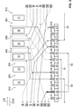
Fig. 2 and summarized in the following table:Start Section Rotor slot Rotor tooth Winding direction Rotor slot End L8/H8 S1 N23 Z3 CW N34 L3/H3 L3 K3 L9 L9/H9 S2 N23 Z2 CCW N12 L4/H4 L4/H4 S1 N61 Z1 CW N12 L11/H11 L11 K5 L5 L5/H5 S2 N34 Z3 CCW N23 L12/H12 L12 K6 L6 L6/H6 S1 N12 Z2 CW N23 L1/H1 L1/H1 S2 N12 Z1 CCW N61 L8/H8 - The first flyer winds a rotor tooth group of the three adjacent rotor teeth Z1, Z2 and Z3. The flyer starts at the commutator bar L8, respectively at the hook H8, and is guided to the rotor slot N23. Subsequently, the rotor tooth Z3 is wound with the coil S1, wherein the coil end is guided from the rotor slot N34 to the hook H3, respectively to the commutator bar L3. From the commutator bar L3 the winding wire is led as contact bridge K3 to the commutator bar L9. The winding wire is led from the commutator bar L9 to the rotor slot N23 and wound as coil S2 around the rotor tooth Z2. The winding wire is then led from the rotor slot N12 to the commutator bar L4, respectively the hook H4. From there, the winding wire is wound around rotor tooth Z1 via rotor slot N61 as coil S1 and is led from rotor slot N12 to commutator bar L11. Subsequently the contact bridge K5 is laid between the commutator bars L11 and L5, and the winding wire is wound around the rotor tooth Z3 via the rotor slot N34 as coil S2. Preferably, the winding wire is not fed directly into the rotor slot 34 from the commutator bar L5, but is first laid 360° around the motor shaft. The winding wire is led from the rotor slot N23 to the hook H12 and laid as contact bridge K6 further to the commutator bar L6. From the commutator bar L6 the winding wire is led further to the rotor slot N12 and laid as coil S1 around the rotor tooth Z2. The end of the coil is led from the rotor slot N23 to the hook H1 of the commutator bar L1, and from there to the rotor slot N12 to be wound as coil S2 around the rotor tooth Z1. Finally, the coil end of the coil S2 is guided from the rotor slot N61 back to the hook H8 of the commutator bar L8.
- The winding scheme of the second flyer is shown in
Fig. 3 and summarized in the following table:Start Section Rotor slot Rotor tooth Winding direction Rotor slot End L2/H2 S1 N56 Z6 CW N61 L9/H9 L9/H9 S2 N56 Z5 CCW N45 L4/H4 L4 K4 L10 L10/H10 S1 N34 Z4 CW N45 L5/H5 L5/H5 S2 N61 Z6 CCW N56 L12/H12 L12 S1 N45 Z5 CW N56 L7/H7 L7 K1 L1 L1/H1 S2 N45 Z4 CCW N34 L8/H8 L8/H8 K2 L2/H2 - The second flyer winds a rotor tooth group of the three adjacent rotor teeth Z4, Z5 and Z6. The winding wire is guided from the commutator bar L2 to the rotor slot N56 and wound as a coil S1 around the rotor tooth Z6. Then the winding wire is led from the rotor slot N61 to the commutator bar L9 and from there to the rotor slot N56. The winding wire is wound as a coil S2 around rotor tooth Z5 and guided via rotor slot N45 to hook H4 of commutator bar L4. The winding wire is led from the commutator bar L4 as contact bridge K4 to the commutator bar L10. Subsequently, the coil S1 is wound around the rotor tooth Z4 in which the start of this coil is led from the commutator bar L10 via the rotor slot N34 to the rotor tooth Z4 and the end of this coil from the rotor slot N45 to the commutator bar L5. The winding wire is then wound around rotor tooth Z6 via rotor slot N61 as coil S2 and is led via rotor slot N56 to commutator bar L12. The coil S1 of rotor tooth Z5 is led from the commutator bar L12 via rotor slot N45 to rotor tooth Z5 and subsequently via rotor slot N56 to commutator bar L7. The winding wire is laid as a contact bridge K1 between the commutator bar L7 and the commutator bar L1. Afterwards, the winding wire is led from the commutator bar L1 to the rotor slot N45, laid around the rotor tooth Z4 as coil S2, and led to the commutator bar L8 via the rotor slot N34. Finally, the winding wire is laid as a contact bridge K2 between the commutator bar L8 and the commutator bar L2.
- In the winding scheme of
Fig. 2 andFig. 3 , thus respectively three adjacent rotor teeth Z1, Z2, Z3 and Z4, Z5, Z6 are wound together as groups of teeth. Preferably the coils S1, S2 and the contact bridges K1 to K6 are wound continuously, i.e. without interruption, for each rotor tooth group. In this winding scheme, respectively the rearmost rotor tooth Z3, Z6 in tangential direction is first wound with a coil S1 and then the middle rotor tooth Z2, Z5 is wound with a coil S2 and subsequently the frontmost rotor tooth Z1, Z4 is wound with a coil S1. Then the same rotor teeth Z1 to Z6 are wound in the same order with the other coil S1, S2. Thus, respectively a first coil S1 and a second coil S2 are wound alternately until each rotor tooth Z1 to Z6 is provided with a first and a second coil S1, S2. The flyers begin and end at diametrically opposed commutator bars L2, L8. - The invention is not limited to the design example described above. Rather, other variants of the invention can be derived from it by the expert without leaving the subject matter of the invention. In particular, all individual features described in connection with the design example can also be combined with each other in other ways without leaving the subject matter of the invention.
-
- 2
- Seat adjustment
- 4
- Vehicle seat
- 6
- Electric motor
- 7
- Stator
- 8
- Rotor
- 10
- Rotor package
- 12
- Rotor winding
- 14
- Commutator
- Z, Z1...Z6
- Rotor tooth
- N, N12...N61
- Rotor winding
- L, L1...L12
- Commutator bar
- H, H1...H12
- Hook
- K, K1...K6
- Contact bridge
- CW, CCW
- Winding direction
Claims (12)
- Rotor (8) of an electric motor (6), comprising a rotor stack (10) with a plurality of radially directed rotor teeth (Z) and with a commutator (14) with a number of commutator bars (L), which is twice as large as the number of rotor teeth (Z), wherein commutator bars (L) lying diametrically opposite one another are respectively connected to a contact bridge (K), and having a rotor winding (12) comprising a plurality of coils (S1, S2) wound on the rotor teeth (Z), wherein each coil (S1, S2) has a first and second coil end and, wherein the first and second coil ends of each coil (S1, S2) are connected directly to commutator bars (L) that are not adjacent to each other.
- Rotor (8) according to claim 1,
characterized in- that each rotor tooth (Z) is wound with a first coil (S1) and with a second coil (S2) of the rotor winding (12), and- that the first and second coils (S1, S2) have opposite winding directions (CW, CCW). - Rotor (8) according to claim 2,
characterized in
that the first and second coils (S1, S2) of in each case three adjacent rotor teeth (Z) are wound continuously from one winding wire. - Rotor (8) according to claim 3,
characterized in
that the winding wire for rotor teeth (Z) arranged successively in the circumferential direction is wound alternately as first and second coils (S1, S2). - Rotor (8) according to one of claims 1 to 4,
characterized in
that a coil end is integrally connected to a contact bridge (K). - Method for manufacturing a rotor (8) of an electric motor (2), comprising a rotor package (10) with a plurality of radially directed rotor teeth (Z) and with a commutator (14) with a number of commutator bars (L), which is twice the number of rotor teeth (Z), wherein diametrically opposed commutator bars (L) are respectively connected to a contact bridge (K),- wherein the rotor teeth (Z) are wound with a plurality of coils (S1, S2) each having first and second coil ends, and- wherein the first and second coil ends of each coil (S1, S2) are connected directly to commutator bars (L) that are not adjacent to each other.
- Method according to claim 6,
characterized in
that each rotor tooth (Z) is wound with a first coil (S1) and with a second coil (S2), and that each commutator bar (L) is connected to at least one of the rotor teeth (Z). - Method according to claim 6 or 7,
characterized in
that two winding tools are provided, that operate at essentially the same time with two different winding wires. - Method according to claim 8,
characterized in
that respectively three adjacent rotor teeth (Z) of the rotor package (10) are wound by each of the winding tools with a concentrate winding. - Method according to claim 8 or 9,
characterized in
that, in case of the three adjacent rotor teeth (Z), each rotor tooth (Z) is first wound with a first or second coil (S1, S2), the winding direction (CW, CCW) for successive rotor teeth (Z) alternating, and each rotor tooth (Z) then being wound with the respective other coil (S1, S2). - Method according to one of claims 8 to 10,
characterized in- that the laying of the contact bridges (K) is divided equally between the two separate winding tools,- that the contact bridges (K) are made with continuous wires, and- that there are no pairs of diametral opposite commutator bars (L) that are linked with two contact bridges (K). - Electric motor (6), in particular a seat motor of a motor vehicle, comprising a rotor (8) according to one of claims 1 to 5.
Priority Applications (3)
| Application Number | Priority Date | Filing Date | Title |
|---|---|---|---|
| PCT/EP2021/073300 WO2022043275A1 (en) | 2020-08-28 | 2021-08-23 | Rotor for an electric motor |
| CN202180053572.4A CN116134711A (en) | 2020-08-28 | 2021-08-23 | Rotor for an electric motor |
| US18/175,707 US20230208264A1 (en) | 2020-08-28 | 2023-02-28 | Rotor of an electric motor, method for manufacturing a rotor and electric motor |
Applications Claiming Priority (1)
| Application Number | Priority Date | Filing Date | Title |
|---|---|---|---|
| EP20193437 | 2020-08-28 |
Publications (1)
| Publication Number | Publication Date |
|---|---|
| EP3961881A1 true EP3961881A1 (en) | 2022-03-02 |
Family
ID=72290957
Family Applications (1)
| Application Number | Title | Priority Date | Filing Date |
|---|---|---|---|
| EP20195778.4A Pending EP3961881A1 (en) | 2020-08-28 | 2020-09-11 | Rotor of an electric motor |
Country Status (4)
| Country | Link |
|---|---|
| US (1) | US20230208264A1 (en) |
| EP (1) | EP3961881A1 (en) |
| CN (1) | CN116134711A (en) |
| WO (1) | WO2022043275A1 (en) |
Citations (6)
| Publication number | Priority date | Publication date | Assignee | Title |
|---|---|---|---|---|
| US4532449A (en) * | 1981-12-14 | 1985-07-30 | Canon Kabushiki Kaisha | DC motor |
| WO2002021665A2 (en) * | 2000-09-06 | 2002-03-14 | Selem Electrotechnologies Inc. | Dc- or ac- commutator motors with concentrated windings |
| EP1834398A1 (en) * | 2004-12-27 | 2007-09-19 | Robert Bosch GmbH | Method for the production of a rotor winding for an electric machine, and electric machine comprising a corresponding rotor winding |
| JP2009060775A (en) * | 2007-08-03 | 2009-03-19 | Mitsuba Corp | Armature for direct-current motor, and the direct-current motor |
| JP4395974B2 (en) * | 2000-03-24 | 2010-01-13 | 株式会社デンソー | DC motor with brush |
| JP2014155416A (en) * | 2013-02-13 | 2014-08-25 | Nissin Kogyo Co Ltd | Electric motor |
Family Cites Families (1)
| Publication number | Priority date | Publication date | Assignee | Title |
|---|---|---|---|---|
| DE10361811A1 (en) | 2003-12-30 | 2005-07-28 | Robert Bosch Gmbh | Electric machine with commutator rotor |
-
2020
- 2020-09-11 EP EP20195778.4A patent/EP3961881A1/en active Pending
-
2021
- 2021-08-23 WO PCT/EP2021/073300 patent/WO2022043275A1/en active Application Filing
- 2021-08-23 CN CN202180053572.4A patent/CN116134711A/en active Pending
-
2023
- 2023-02-28 US US18/175,707 patent/US20230208264A1/en active Pending
Patent Citations (6)
| Publication number | Priority date | Publication date | Assignee | Title |
|---|---|---|---|---|
| US4532449A (en) * | 1981-12-14 | 1985-07-30 | Canon Kabushiki Kaisha | DC motor |
| JP4395974B2 (en) * | 2000-03-24 | 2010-01-13 | 株式会社デンソー | DC motor with brush |
| WO2002021665A2 (en) * | 2000-09-06 | 2002-03-14 | Selem Electrotechnologies Inc. | Dc- or ac- commutator motors with concentrated windings |
| EP1834398A1 (en) * | 2004-12-27 | 2007-09-19 | Robert Bosch GmbH | Method for the production of a rotor winding for an electric machine, and electric machine comprising a corresponding rotor winding |
| JP2009060775A (en) * | 2007-08-03 | 2009-03-19 | Mitsuba Corp | Armature for direct-current motor, and the direct-current motor |
| JP2014155416A (en) * | 2013-02-13 | 2014-08-25 | Nissin Kogyo Co Ltd | Electric motor |
Also Published As
| Publication number | Publication date |
|---|---|
| US20230208264A1 (en) | 2023-06-29 |
| CN116134711A (en) | 2023-05-16 |
| WO2022043275A1 (en) | 2022-03-03 |
Similar Documents
| Publication | Publication Date | Title |
|---|---|---|
| US9859764B2 (en) | Rotary electric machine with distributed armature winding | |
| US7239063B2 (en) | Motor having supply brushes | |
| US10355547B2 (en) | Rotary electric machine | |
| USRE45912E1 (en) | Electric motor | |
| KR101730525B1 (en) | Brushless synchronous motor | |
| US10236738B2 (en) | Rotary electric machine | |
| US10461591B2 (en) | Rotary electric machine with armature coil end top portions displaced in a radial direction | |
| CA2361368C (en) | Brushless doubly-fed induction machines employing dual cage rotors | |
| US8188632B2 (en) | Miniature motor, and its manufacturing method | |
| US10170950B2 (en) | Rotary electric machine and method for manufacturing an armature that is used in the rotary electric machine | |
| EP2226923B1 (en) | Coils | |
| US20080093943A1 (en) | Method for the Production of a Rotor Winding for an Electric Machine, and Electric Machine Having a Corresponding Rotor Winding | |
| US20120098379A1 (en) | Brushless motor and electric power steering system | |
| US20090309451A1 (en) | Electrical machine with single-tooth rotor winding | |
| EP1820249A2 (en) | Motor armature having distributed windings for reducing arcing | |
| US20100264772A1 (en) | Direct current motor | |
| US8575811B2 (en) | Motor | |
| WO2021220916A1 (en) | Stator having coil structure of distributed winding, and three-phase ac electric motor comprising said stator | |
| US20090236928A1 (en) | Electrical machine | |
| EP3961881A1 (en) | Rotor of an electric motor | |
| US8946965B2 (en) | Armature of electric motor and electric motor | |
| US11075557B2 (en) | Rotor of rotating electrical machine and associated fabrication process | |
| CN109995157B (en) | Rotor for a rotating electrical machine and associated manufacturing process | |
| US10879774B2 (en) | Electric power steering system and brush motor thereof | |
| WO2023140071A1 (en) | Motor stator and motor provided with same |
Legal Events
| Date | Code | Title | Description |
|---|---|---|---|
| PUAI | Public reference made under article 153(3) epc to a published international application that has entered the european phase |
Free format text: ORIGINAL CODE: 0009012 |
|
| STAA | Information on the status of an ep patent application or granted ep patent |
Free format text: STATUS: THE APPLICATION HAS BEEN PUBLISHED |
|
| AK | Designated contracting states |
Kind code of ref document: A1 Designated state(s): AL AT BE BG CH CY CZ DE DK EE ES FI FR GB GR HR HU IE IS IT LI LT LU LV MC MK MT NL NO PL PT RO RS SE SI SK SM TR |
|
| STAA | Information on the status of an ep patent application or granted ep patent |
Free format text: STATUS: REQUEST FOR EXAMINATION WAS MADE |
|
| 17P | Request for examination filed |
Effective date: 20220902 |
|
| RAV | Requested validation state of the european patent: fee paid |
Extension state: TN Effective date: 20220902 Extension state: MD Effective date: 20220902 Extension state: MA Effective date: 20220902 Extension state: KH Effective date: 20220902 |
|
| RAX | Requested extension states of the european patent have changed |
Extension state: ME Payment date: 20220902 Extension state: BA Payment date: 20220902 |
|
| RBV | Designated contracting states (corrected) |
Designated state(s): AL AT BE BG CH CY CZ DE DK EE ES FI FR GB GR HR HU IE IS IT LI LT LU LV MC MK MT NL NO PL PT RO RS SE SI SK SM TR |
|
| STAA | Information on the status of an ep patent application or granted ep patent |
Free format text: STATUS: EXAMINATION IS IN PROGRESS |
|
| 17Q | First examination report despatched |
Effective date: 20231205 |