EP3961663B1 - Stationäre induktionsvorrichtung - Google Patents
Stationäre induktionsvorrichtung Download PDFInfo
- Publication number
- EP3961663B1 EP3961663B1 EP19926516.6A EP19926516A EP3961663B1 EP 3961663 B1 EP3961663 B1 EP 3961663B1 EP 19926516 A EP19926516 A EP 19926516A EP 3961663 B1 EP3961663 B1 EP 3961663B1
- Authority
- EP
- European Patent Office
- Prior art keywords
- plate
- insulating
- flow path
- holes
- windings
- Prior art date
- Legal status (The legal status is an assumption and is not a legal conclusion. Google has not performed a legal analysis and makes no representation as to the accuracy of the status listed.)
- Active
Links
Images


Classifications
-
- H—ELECTRICITY
- H01—ELECTRIC ELEMENTS
- H01F—MAGNETS; INDUCTANCES; TRANSFORMERS; SELECTION OF MATERIALS FOR THEIR MAGNETIC PROPERTIES
- H01F27/00—Details of transformers or inductances, in general
- H01F27/08—Cooling; Ventilating
- H01F27/10—Liquid cooling
- H01F27/12—Oil cooling
- H01F27/125—Cooling by synthetic insulating and incombustible liquid
-
- H—ELECTRICITY
- H01—ELECTRIC ELEMENTS
- H01F—MAGNETS; INDUCTANCES; TRANSFORMERS; SELECTION OF MATERIALS FOR THEIR MAGNETIC PROPERTIES
- H01F27/00—Details of transformers or inductances, in general
- H01F27/28—Coils; Windings; Conductive connections
- H01F27/32—Insulating of coils, windings, or parts thereof
- H01F27/322—Insulating of coils, windings, or parts thereof the insulation forming channels for circulation of the fluid
-
- H—ELECTRICITY
- H01—ELECTRIC ELEMENTS
- H01F—MAGNETS; INDUCTANCES; TRANSFORMERS; SELECTION OF MATERIALS FOR THEIR MAGNETIC PROPERTIES
- H01F27/00—Details of transformers or inductances, in general
- H01F27/02—Casings
- H01F27/025—Constructional details relating to cooling
-
- H—ELECTRICITY
- H01—ELECTRIC ELEMENTS
- H01F—MAGNETS; INDUCTANCES; TRANSFORMERS; SELECTION OF MATERIALS FOR THEIR MAGNETIC PROPERTIES
- H01F27/00—Details of transformers or inductances, in general
- H01F27/08—Cooling; Ventilating
- H01F27/10—Liquid cooling
- H01F27/12—Oil cooling
-
- H—ELECTRICITY
- H01—ELECTRIC ELEMENTS
- H01F—MAGNETS; INDUCTANCES; TRANSFORMERS; SELECTION OF MATERIALS FOR THEIR MAGNETIC PROPERTIES
- H01F27/00—Details of transformers or inductances, in general
- H01F27/28—Coils; Windings; Conductive connections
- H01F27/30—Fastening or clamping coils, windings, or parts thereof together; Fastening or mounting coils or windings on core, casing, or other support
- H01F27/306—Fastening or mounting coils or windings on core, casing or other support
-
- H—ELECTRICITY
- H01—ELECTRIC ELEMENTS
- H01F—MAGNETS; INDUCTANCES; TRANSFORMERS; SELECTION OF MATERIALS FOR THEIR MAGNETIC PROPERTIES
- H01F27/00—Details of transformers or inductances, in general
- H01F27/28—Coils; Windings; Conductive connections
- H01F27/32—Insulating of coils, windings, or parts thereof
- H01F27/324—Insulation between coil and core, between different winding sections, around the coil; Other insulation structures
Definitions
- the present invention relates to a stationary induction apparatus.
- Japanese Utility Model Laying-Open No. 58-196814 (PTL 1) is a document that discloses a configuration of a stationary induction apparatus.
- a transformer which is a stationary induction apparatus described in PTL 1
- a high-voltage winding and a low-voltage winding are insulated from each other by a flat interwinding insulating plate.
- an oil duct is formed by affixing insulating pieces to a surface of the flat insulating plate.
- a tank contains these components, and is filled with insulating oil.
- the insulating oil enters between the high-voltage winding and the low-voltage winding via one ends of the windings, and is heated by receiving heat of these windings while passing between them.
- the insulating oil is delivered to the outside via the other ends of the windings, into an oil cooler by an oil pump through a pipe, and is then cooled by a blower and returns to the tank.
- the flow path for insulating oil can be readily formed between the plurality of windings by disposing the first plate-like portion and the second plate-like portion to be adjacent to each other, without arranging a plurality of insulating pieces on the insulating plate.
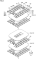
- Fig. 1 is a perspective view showing an external appearance of a stationary not covered by the claims.
- induction apparatus according to a first embodiment
- Fig. 2 is a perspective view showing part of a configuration of the stationary induction apparatus according to the first embodiment.
- Fig. 3 is a partial cross-sectional view of the stationary induction apparatus shown in Fig. 1 when viewed in a direction of arrows of line III-III.
- Fig. 4 is an exploded perspective view showing a multilayer structure of a plurality of windings and a plurality of insulating plates included in the stationary induction apparatus according to the first embodiment.
- stationary induction apparatus 100 includes a core 110, a plurality of windings 120, a plurality of insulating plates 130, and a tank 140.
- the plurality of insulating plates 130 are not illustrated in Figs. 2 and 3 .
- core 110 includes a main leg 111 and side legs 112. Side legs 112 are connected to main leg 111.
- the plurality of windings 120 include a plurality of high-voltage windings 120a and a plurality of low-voltage windings 120b. In a central axis direction of the plurality of windings 120, the plurality of high-voltage windings 120a are located so as to be sandwiched between a pair of the plurality of low-voltage windings 120b.
- tank 140 contains core 110, the plurality of windings 120 and the plurality of insulating plates 130.
- Tank 140 is filled with insulating oil.
- Tank 140 is configured such that the insulating oil flows within tank 140 in a first direction D1 orthogonal to the central axis direction of the plurality of windings 120.
- Circulation pipe 151 is further connected to a cooling container 153.
- Cooling container 153 is cooled from outside by air delivered from an electric blower 152. As a result, the insulating oil that has flowed into cooling container 153 is cooled, and then flows into circulation pipe 151 again.
- connection portions 141 The insulating oil that has flowed in via one of connection portions 141 flows through a flow path 10 for insulating oil that is formed between the plurality of windings 120 adjacent to each other. As a result, heat of windings 120 adjacent to flow path 10 is transferred to the insulating oil. The plurality of windings 120 are thereby cooled.
- Flow path 10 is formed of the plurality of insulating plates 130. Flow path 10 in the present embodiment will be hereinafter described along with the configuration of the plurality of insulating plates 130.
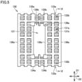
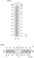
- Fig. 5 is a diagram showing a shape of an insulating plate in the first embodiment.
- Fig. 6 is a cross-sectional view of the insulating plate shown in Fig. 5 when viewed in a direction of arrows of line VI-VI.
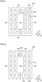
- Fig. 7 is a diagram showing a shape of a first plate-like portion of the insulating plate in the first embodiment.
- Fig. 8 is a diagram showing a shape of a second plate-like portion of the insulating plate in the first embodiment.
- the plurality of windings 120 adjacent to insulating plate 130 are also illustrated in Fig. 6 .
- each of the plurality of insulating plates 130 has a rectangular outer shape, when viewed in the central axis direction of the plurality of windings 120.
- Each of the plurality of insulating plates 130 is located such that a longitudinal direction of each of the plurality of insulating plates 130 is along first direction D1. That is, each of the plurality of insulating plates 130 is located such that a transverse direction of each of the plurality of insulating plates 130 is along a second direction D2 orthogonal to both the central axis direction and first direction D1.
- Each of the plurality of insulating plates 130 is provided with an opening 137 extending therethrough in the central axis direction.
- Core 110 shown in Fig. 2 is located in opening 137.
- main leg 111 is located in opening 137.
- each of the plurality of insulating plates 130 includes a first plate-like portion 130a and a second plate-like portion 130b adjacent to each other in the central axis direction.
- each of the plurality of insulating plates 130 is formed of first plate-like portion 130a and second plate-like portion 130b.
- Each of first plate-like portion 130a and second plate-like portion 130b is made of an insulating material, for example, insulating paper such as pressboard, or an insulating material such as polyamide.
- first plate-like portion 130a is provided with a plurality of first holes 131a extending therethrough in the central axis direction.
- first hole 131a When viewed in the central axis direction, first hole 131a has a rectangular outer shape, specifically, a square outer shape.
- Side edges 136a located at opposite sides of first plate-like portion 130a in second direction D2 each have a linear outer shape along first direction D1.
- first hole 131a, and first notch 132a and second notch 133a in first plate-like portion 130a when viewed in the central axis direction are not particularly limited.
- the outer shapes of first hole 131a, and first notch 132a and second notch 133a in first plate-like portion 130a when viewed in the central axis direction can be varied as appropriate so as to reduce pressure loss caused by the shape of flow path 10 for insulating oil.
- Second plate-like portion 130b is provided with a second notch 133b at the other edge 135b in first direction D1. Specifically, second plate-like portion 130b is provided with a plurality of second notches 133b. In the present embodiment, each corner of each of the plurality of second notches 133b in second plate-like portion 130b forms a right angle.
- Second plate-like portion 130b located at opposite sides of second plate-like portion 130b in second direction D2 each have a linear outer shape along first direction D1.
- Second plate-like portion 130b is provided with a plurality of inner peripheral notches 139b at inner peripheral edges 138b.
- first plate-like portion 130a and second plate-like portion 130b is provided with first notch 132a, 132b at one edge 134a, 134b in first direction D1, and is provided with second notch 133a, 133b at the other edge 135a, 135b in first direction D1.
- first hole 131a located closest to one edge 134a overlaps first notch 132b.
- Each of the plurality of second holes 131b overlaps both of two first holes 131a adjacent to each other in first direction D1.
- First hole 131a located closest to 135a overlaps second notch 133b.
- Linear flow path 11 is configured in this manner.
- a stationary induction apparatus will be not covered by the claims hereinafter described.
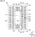
- the stationary induction apparatus according to the second embodiment is different only in the configuration of each of the plurality of insulating plates from stationary induction apparatus 100 according to the first embodiment. Thus, a description of the configuration similar to that of stationary induction apparatus 100 according to the first embodiment will not be repeated.
- each of the plurality of first holes 431a and the plurality of second holes 431b is configured such that, when viewed in the central axis direction, a central portion of each of the plurality of first holes 431a and a central portion of each of the plurality of second holes 431b are located in a zigzag relation to each other.
- Fig. 23 is a cross-sectional view showing a configuration of an insulating plate in the fifth embodiment.
- insulating plate 430 in the fourth embodiment is shown in the same cross section as in Fig. 19 .
Landscapes
- Engineering & Computer Science (AREA)
- Power Engineering (AREA)
- Chemical & Material Sciences (AREA)
- Combustion & Propulsion (AREA)
- Coils Of Transformers For General Uses (AREA)
- Insulating Of Coils (AREA)
- Transformer Cooling (AREA)
Claims (2)
- Stationäre Induktionsvorrichtung, umfassend:einen Kern (110);eine Mehrzahl von Wicklungen (120), welche mit dem Kern (110) als eine Mittelachse um den Kern (110) gewickelt sind und koaxial angeordnet sind,eine Mehrzahl isolierender Platten (130, 230, 330), welche jeweils derart angeordnet sind, dass sie sandwichartig zwischen jeweils zwei benachbarten Wicklungen (120) der Mehrzahl von Wicklungen (120) angeordnet sind, undeinen Behälter (140), um den Kern (110) die Mehrzahl von Wicklungen (120) und die Mehrzahl isolierender Platten (330) zu enthalten, wobei der Behälter (140) mit einem isolierenden Öl gefüllt ist,wobei der Behälter (140) derart eingerichtet ist, dass das isolierende Öl in einer zu einer Mittelachsenrichtung der Mehrzahl von Wicklungen (120) orthogonalen ersten Richtung (D1) innerhalb des Behälters (140) strömt,wobei die Mehrzahl isolierender Platten (130, 230, 330) jeweils einen ersten plattenartigen Abschnitt (330a) und einen zweiten plattenartigen Abschnitt (330b) umfasst, welche in der Mittelachsenrichtung zueinander benachbart sind,wobei der erste plattenartige Abschnitt (330a) mit einer Mehrzahl erster Löcher (331a) bereitgestellt ist, welche sich in der Mittelachsenrichtung dadurch erstrecken,wobei der zweite plattenartige Abschnitt (330b) mit einer Mehrzahl zweiter Löcher (331b) bereitgestellt ist, welche sich in der Mittelachsenrichtung dadurch erstrecken,wobei wenigstens einer des ersten plattenartigen Abschnitts (330a) und des zweiten plattenartigen Abschnitts (330b) in der ersten Richtung (D1) an einem Rand (134a, 134b) mit einer ersten Einkerbung (132a, 132b) bereitgestellt ist und in der ersten Richtung (D1) an dem anderen Rand (135a, 135b) mit einer zweiten Einkerbung (133a, 133b) bereitgestellt ist undwobei die Mehrzahl erster Löcher (331a), die Mehrzahl zweiter Löcher (331b), die erste Einkerbung (132a, 132b) und die zweite Einkerbung (133a, 133b) einander überlappen, um dadurch einen Strömungsweg (10) zu bilden, welcher eine Seite und die andere Seite jeder der Mehrzahl von Platten (130, 230, 330) verbindet und durch welchen das isolierende Öl in der ersten Richtung (D1) strömen kann, wobeider Strömungsweg (10), wenn in der Mittelachsenrichtung betrachtet, einen linearen Strömungsweg (11) umfasst, welcher entlang der ersten Richtung (D1) gebildet ist,der Strömungsweg (10), wenn in der Mittelachsenrichtung betrachtet, eine Mehrzahl der linearen Strömungswege (11X, 11Y) umfasst,die Mehrzahl erster Löcher (331a), welche einen (11X) der Mehrzahl der linearen Strömungswege (11X, 11Y) bilden, welche benachbart zueinander sind, und die Mehrzahl erster Löcher (331a), welche den anderen linearen Strömungsweg (11Y) bilden, in der ersten Richtung (D1) in einer versetzten Beziehung zueinander angeordnet sind unddie Mehrzahl zweiter Löcher (331b), welche einen (11X) der Mehrzahl der linearen Strömungswege (11X, 11Y) bilden, welche benachbart zueinander sind, und die Mehrzahl zweiter Löcher (331b), welche den anderen linearen Strömungsweg (11Y) bilden, in der ersten Richtung (D1) in einer versetzten Beziehung zueinander angeordnet sind.
- Stationäre Induktionsvorrichtung nach Anspruch 1, wobeidie Mehrzahl isolierender Platten jeweils ferner einen dritten plattenartigen Abschnitt (530c) umfasst, welcher in der Mittelachsenrichtung an einer dem ersten plattenartigen Abschnitt (430a) entgegengesetzten Seite und benachbart zu dem zweiten plattenartigen Abschnitt (430b) angeordnet ist, undder dritte plattenartige Abschnitt (530c) in einer Form identisch zu dem ersten plattenartigen Abschnitt (430a) ist und in Bezug auf den zweiten plattenartigen Abschnitt (430b) symmetrisch zu dem ersten plattenartigen Abschnitt (430a) angeordnet ist.
Applications Claiming Priority (1)
| Application Number | Priority Date | Filing Date | Title |
|---|---|---|---|
| PCT/JP2019/017608 WO2020217376A1 (ja) | 2019-04-25 | 2019-04-25 | 静止誘導機器 |
Publications (3)
| Publication Number | Publication Date |
|---|---|
| EP3961663A1 EP3961663A1 (de) | 2022-03-02 |
| EP3961663A4 EP3961663A4 (de) | 2022-05-04 |
| EP3961663B1 true EP3961663B1 (de) | 2023-12-20 |
Family
ID=68692061
Family Applications (1)
| Application Number | Title | Priority Date | Filing Date |
|---|---|---|---|
| EP19926516.6A Active EP3961663B1 (de) | 2019-04-25 | 2019-04-25 | Stationäre induktionsvorrichtung |
Country Status (4)
| Country | Link |
|---|---|
| US (1) | US12009134B2 (de) |
| EP (1) | EP3961663B1 (de) |
| JP (1) | JP6612009B1 (de) |
| WO (1) | WO2020217376A1 (de) |
Families Citing this family (1)
| Publication number | Priority date | Publication date | Assignee | Title |
|---|---|---|---|---|
| CN115380342A (zh) * | 2020-03-31 | 2022-11-22 | 通用电气公司 | 用于高功率密度(hpd)变压器的液体/流体冷却系统 |
Family Cites Families (7)
| Publication number | Priority date | Publication date | Assignee | Title |
|---|---|---|---|---|
| JPS5033616Y1 (de) | 1969-12-17 | 1975-10-01 | ||
| JPS5314135B2 (de) * | 1972-02-05 | 1978-05-15 | ||
| JPS5426623U (de) * | 1977-07-26 | 1979-02-21 | ||
| JPS58196814U (ja) | 1982-06-24 | 1983-12-27 | 株式会社東芝 | 外鉄形油入変圧器 |
| US7760060B2 (en) * | 2006-07-10 | 2010-07-20 | Mitsubishi Electric Corporation | Vehicle transformer |
| US8547193B2 (en) | 2009-10-21 | 2013-10-01 | Mitsubishi Electric Corporation | Stationary induction apparatus |
| EP3171372B1 (de) * | 2014-07-17 | 2019-03-20 | Mitsubishi Electric Corporation | Fahrzeuginterne spannungsumwandlungsvorrichtung |
-
2019
- 2019-04-25 EP EP19926516.6A patent/EP3961663B1/de active Active
- 2019-04-25 WO PCT/JP2019/017608 patent/WO2020217376A1/ja not_active Ceased
- 2019-04-25 JP JP2019547737A patent/JP6612009B1/ja not_active Expired - Fee Related
- 2019-04-25 US US17/429,081 patent/US12009134B2/en active Active
Also Published As
| Publication number | Publication date |
|---|---|
| WO2020217376A1 (ja) | 2020-10-29 |
| EP3961663A4 (de) | 2022-05-04 |
| US20220020520A1 (en) | 2022-01-20 |
| US12009134B2 (en) | 2024-06-11 |
| JPWO2020217376A1 (ja) | 2021-05-13 |
| EP3961663A1 (de) | 2022-03-02 |
| JP6612009B1 (ja) | 2019-11-27 |
Similar Documents
| Publication | Publication Date | Title |
|---|---|---|
| US3183461A (en) | Magnetic core structure with cooling passages therein | |
| US9805852B2 (en) | Transformer core | |
| US8274351B2 (en) | Transformer device | |
| US20150302968A1 (en) | Magnetic element with multiple air gaps | |
| US9947453B2 (en) | Stationary induction electric apparatus | |
| EP3961663B1 (de) | Stationäre induktionsvorrichtung | |
| KR20000074890A (ko) | 방열 리브를 가지는 고압 트랜스포머 | |
| CN105895328A (zh) | 三相五柱式铁芯和静止电磁设备 | |
| US9576709B2 (en) | Transformer having a stacked core | |
| CN110914938A (zh) | 平面型变压器和dcdc转换器 | |
| KR20220054393A (ko) | 권철심 | |
| JP4387769B2 (ja) | 巻鉄心及び変圧器 | |
| CA1198187A (en) | Transformer core cooling arrangement | |
| US10102966B2 (en) | Stationary induction apparatus | |
| JP6572541B2 (ja) | 変圧器 | |
| JP5930780B2 (ja) | リアクトル | |
| US3349357A (en) | Transformer core reinforcing plate | |
| US20160268035A1 (en) | Vehicle-mounted transformer | |
| US11581119B2 (en) | Magnetic device and method of manufacturing the same | |
| US4477791A (en) | Spacer block pattern for electrical inductive apparatus | |
| US9941043B2 (en) | Core for an electrical induction device | |
| JPH0145204B2 (de) | ||
| US714232A (en) | Transformer, inductor, &c. | |
| US2812505A (en) | Magnetic core for stationary electrical induction apparatus | |
| US20170301450A1 (en) | Cooling structure for coil component |
Legal Events
| Date | Code | Title | Description |
|---|---|---|---|
| STAA | Information on the status of an ep patent application or granted ep patent |
Free format text: STATUS: THE INTERNATIONAL PUBLICATION HAS BEEN MADE |
|
| PUAI | Public reference made under article 153(3) epc to a published international application that has entered the european phase |
Free format text: ORIGINAL CODE: 0009012 |
|
| STAA | Information on the status of an ep patent application or granted ep patent |
Free format text: STATUS: REQUEST FOR EXAMINATION WAS MADE |
|
| 17P | Request for examination filed |
Effective date: 20210827 |
|
| AK | Designated contracting states |
Kind code of ref document: A1 Designated state(s): AL AT BE BG CH CY CZ DE DK EE ES FI FR GB GR HR HU IE IS IT LI LT LU LV MC MK MT NL NO PL PT RO RS SE SI SK SM TR |
|
| A4 | Supplementary search report drawn up and despatched |
Effective date: 20220331 |
|
| RIC1 | Information provided on ipc code assigned before grant |
Ipc: H01F 27/12 20060101ALI20220325BHEP Ipc: H01F 27/32 20060101AFI20220325BHEP |
|
| DAV | Request for validation of the european patent (deleted) | ||
| DAX | Request for extension of the european patent (deleted) | ||
| GRAP | Despatch of communication of intention to grant a patent |
Free format text: ORIGINAL CODE: EPIDOSNIGR1 |
|
| STAA | Information on the status of an ep patent application or granted ep patent |
Free format text: STATUS: GRANT OF PATENT IS INTENDED |
|
| INTG | Intention to grant announced |
Effective date: 20230711 |
|
| P01 | Opt-out of the competence of the unified patent court (upc) registered |
Effective date: 20230919 |
|
| GRAS | Grant fee paid |
Free format text: ORIGINAL CODE: EPIDOSNIGR3 |
|
| GRAA | (expected) grant |
Free format text: ORIGINAL CODE: 0009210 |
|
| STAA | Information on the status of an ep patent application or granted ep patent |
Free format text: STATUS: THE PATENT HAS BEEN GRANTED |
|
| AK | Designated contracting states |
Kind code of ref document: B1 Designated state(s): AL AT BE BG CH CY CZ DE DK EE ES FI FR GB GR HR HU IE IS IT LI LT LU LV MC MK MT NL NO PL PT RO RS SE SI SK SM TR |
|
| REG | Reference to a national code |
Ref country code: GB Ref legal event code: FG4D |
|
| REG | Reference to a national code |
Ref country code: DE Ref legal event code: R096 Ref document number: 602019043812 Country of ref document: DE |
|
| REG | Reference to a national code |
Ref country code: CH Ref legal event code: EP |
|
| REG | Reference to a national code |
Ref country code: IE Ref legal event code: FG4D |
|
| PG25 | Lapsed in a contracting state [announced via postgrant information from national office to epo] |
Ref country code: GR Free format text: LAPSE BECAUSE OF FAILURE TO SUBMIT A TRANSLATION OF THE DESCRIPTION OR TO PAY THE FEE WITHIN THE PRESCRIBED TIME-LIMIT Effective date: 20240321 |
|
| REG | Reference to a national code |
Ref country code: LT Ref legal event code: MG9D |
|
| PG25 | Lapsed in a contracting state [announced via postgrant information from national office to epo] |
Ref country code: LT Free format text: LAPSE BECAUSE OF FAILURE TO SUBMIT A TRANSLATION OF THE DESCRIPTION OR TO PAY THE FEE WITHIN THE PRESCRIBED TIME-LIMIT Effective date: 20231220 |
|
| REG | Reference to a national code |
Ref country code: NL Ref legal event code: MP Effective date: 20231220 |
|
| PG25 | Lapsed in a contracting state [announced via postgrant information from national office to epo] |
Ref country code: ES Free format text: LAPSE BECAUSE OF FAILURE TO SUBMIT A TRANSLATION OF THE DESCRIPTION OR TO PAY THE FEE WITHIN THE PRESCRIBED TIME-LIMIT Effective date: 20231220 |
|
| PG25 | Lapsed in a contracting state [announced via postgrant information from national office to epo] |
Ref country code: LT Free format text: LAPSE BECAUSE OF FAILURE TO SUBMIT A TRANSLATION OF THE DESCRIPTION OR TO PAY THE FEE WITHIN THE PRESCRIBED TIME-LIMIT Effective date: 20231220 Ref country code: GR Free format text: LAPSE BECAUSE OF FAILURE TO SUBMIT A TRANSLATION OF THE DESCRIPTION OR TO PAY THE FEE WITHIN THE PRESCRIBED TIME-LIMIT Effective date: 20240321 Ref country code: FI Free format text: LAPSE BECAUSE OF FAILURE TO SUBMIT A TRANSLATION OF THE DESCRIPTION OR TO PAY THE FEE WITHIN THE PRESCRIBED TIME-LIMIT Effective date: 20231220 Ref country code: ES Free format text: LAPSE BECAUSE OF FAILURE TO SUBMIT A TRANSLATION OF THE DESCRIPTION OR TO PAY THE FEE WITHIN THE PRESCRIBED TIME-LIMIT Effective date: 20231220 Ref country code: BG Free format text: LAPSE BECAUSE OF FAILURE TO SUBMIT A TRANSLATION OF THE DESCRIPTION OR TO PAY THE FEE WITHIN THE PRESCRIBED TIME-LIMIT Effective date: 20240320 |
|
| REG | Reference to a national code |
Ref country code: AT Ref legal event code: MK05 Ref document number: 1643182 Country of ref document: AT Kind code of ref document: T Effective date: 20231220 |
|
| PG25 | Lapsed in a contracting state [announced via postgrant information from national office to epo] |
Ref country code: NL Free format text: LAPSE BECAUSE OF FAILURE TO SUBMIT A TRANSLATION OF THE DESCRIPTION OR TO PAY THE FEE WITHIN THE PRESCRIBED TIME-LIMIT Effective date: 20231220 |
|
| PG25 | Lapsed in a contracting state [announced via postgrant information from national office to epo] |
Ref country code: SE Free format text: LAPSE BECAUSE OF FAILURE TO SUBMIT A TRANSLATION OF THE DESCRIPTION OR TO PAY THE FEE WITHIN THE PRESCRIBED TIME-LIMIT Effective date: 20231220 Ref country code: RS Free format text: LAPSE BECAUSE OF FAILURE TO SUBMIT A TRANSLATION OF THE DESCRIPTION OR TO PAY THE FEE WITHIN THE PRESCRIBED TIME-LIMIT Effective date: 20231220 Ref country code: NO Free format text: LAPSE BECAUSE OF FAILURE TO SUBMIT A TRANSLATION OF THE DESCRIPTION OR TO PAY THE FEE WITHIN THE PRESCRIBED TIME-LIMIT Effective date: 20240320 Ref country code: NL Free format text: LAPSE BECAUSE OF FAILURE TO SUBMIT A TRANSLATION OF THE DESCRIPTION OR TO PAY THE FEE WITHIN THE PRESCRIBED TIME-LIMIT Effective date: 20231220 Ref country code: LV Free format text: LAPSE BECAUSE OF FAILURE TO SUBMIT A TRANSLATION OF THE DESCRIPTION OR TO PAY THE FEE WITHIN THE PRESCRIBED TIME-LIMIT Effective date: 20231220 Ref country code: HR Free format text: LAPSE BECAUSE OF FAILURE TO SUBMIT A TRANSLATION OF THE DESCRIPTION OR TO PAY THE FEE WITHIN THE PRESCRIBED TIME-LIMIT Effective date: 20231220 |
|
| PG25 | Lapsed in a contracting state [announced via postgrant information from national office to epo] |
Ref country code: IS Free format text: LAPSE BECAUSE OF FAILURE TO SUBMIT A TRANSLATION OF THE DESCRIPTION OR TO PAY THE FEE WITHIN THE PRESCRIBED TIME-LIMIT Effective date: 20240420 |
|
| PG25 | Lapsed in a contracting state [announced via postgrant information from national office to epo] |
Ref country code: CZ Free format text: LAPSE BECAUSE OF FAILURE TO SUBMIT A TRANSLATION OF THE DESCRIPTION OR TO PAY THE FEE WITHIN THE PRESCRIBED TIME-LIMIT Effective date: 20231220 Ref country code: AT Free format text: LAPSE BECAUSE OF FAILURE TO SUBMIT A TRANSLATION OF THE DESCRIPTION OR TO PAY THE FEE WITHIN THE PRESCRIBED TIME-LIMIT Effective date: 20231220 |
|
| PG25 | Lapsed in a contracting state [announced via postgrant information from national office to epo] |
Ref country code: SK Free format text: LAPSE BECAUSE OF FAILURE TO SUBMIT A TRANSLATION OF THE DESCRIPTION OR TO PAY THE FEE WITHIN THE PRESCRIBED TIME-LIMIT Effective date: 20231220 |
|
| PG25 | Lapsed in a contracting state [announced via postgrant information from national office to epo] |
Ref country code: SM Free format text: LAPSE BECAUSE OF FAILURE TO SUBMIT A TRANSLATION OF THE DESCRIPTION OR TO PAY THE FEE WITHIN THE PRESCRIBED TIME-LIMIT Effective date: 20231220 Ref country code: SK Free format text: LAPSE BECAUSE OF FAILURE TO SUBMIT A TRANSLATION OF THE DESCRIPTION OR TO PAY THE FEE WITHIN THE PRESCRIBED TIME-LIMIT Effective date: 20231220 Ref country code: RO Free format text: LAPSE BECAUSE OF FAILURE TO SUBMIT A TRANSLATION OF THE DESCRIPTION OR TO PAY THE FEE WITHIN THE PRESCRIBED TIME-LIMIT Effective date: 20231220 Ref country code: IT Free format text: LAPSE BECAUSE OF FAILURE TO SUBMIT A TRANSLATION OF THE DESCRIPTION OR TO PAY THE FEE WITHIN THE PRESCRIBED TIME-LIMIT Effective date: 20231220 Ref country code: IS Free format text: LAPSE BECAUSE OF FAILURE TO SUBMIT A TRANSLATION OF THE DESCRIPTION OR TO PAY THE FEE WITHIN THE PRESCRIBED TIME-LIMIT Effective date: 20240420 Ref country code: EE Free format text: LAPSE BECAUSE OF FAILURE TO SUBMIT A TRANSLATION OF THE DESCRIPTION OR TO PAY THE FEE WITHIN THE PRESCRIBED TIME-LIMIT Effective date: 20231220 Ref country code: CZ Free format text: LAPSE BECAUSE OF FAILURE TO SUBMIT A TRANSLATION OF THE DESCRIPTION OR TO PAY THE FEE WITHIN THE PRESCRIBED TIME-LIMIT Effective date: 20231220 Ref country code: AT Free format text: LAPSE BECAUSE OF FAILURE TO SUBMIT A TRANSLATION OF THE DESCRIPTION OR TO PAY THE FEE WITHIN THE PRESCRIBED TIME-LIMIT Effective date: 20231220 |
|
| PG25 | Lapsed in a contracting state [announced via postgrant information from national office to epo] |
Ref country code: PL Free format text: LAPSE BECAUSE OF FAILURE TO SUBMIT A TRANSLATION OF THE DESCRIPTION OR TO PAY THE FEE WITHIN THE PRESCRIBED TIME-LIMIT Effective date: 20231220 Ref country code: PT Free format text: LAPSE BECAUSE OF FAILURE TO SUBMIT A TRANSLATION OF THE DESCRIPTION OR TO PAY THE FEE WITHIN THE PRESCRIBED TIME-LIMIT Effective date: 20240422 |
|
| PG25 | Lapsed in a contracting state [announced via postgrant information from national office to epo] |
Ref country code: PT Free format text: LAPSE BECAUSE OF FAILURE TO SUBMIT A TRANSLATION OF THE DESCRIPTION OR TO PAY THE FEE WITHIN THE PRESCRIBED TIME-LIMIT Effective date: 20240422 Ref country code: PL Free format text: LAPSE BECAUSE OF FAILURE TO SUBMIT A TRANSLATION OF THE DESCRIPTION OR TO PAY THE FEE WITHIN THE PRESCRIBED TIME-LIMIT Effective date: 20231220 |
|
| REG | Reference to a national code |
Ref country code: DE Ref legal event code: R097 Ref document number: 602019043812 Country of ref document: DE |
|
| PG25 | Lapsed in a contracting state [announced via postgrant information from national office to epo] |
Ref country code: DK Free format text: LAPSE BECAUSE OF FAILURE TO SUBMIT A TRANSLATION OF THE DESCRIPTION OR TO PAY THE FEE WITHIN THE PRESCRIBED TIME-LIMIT Effective date: 20231220 |
|
| PLBE | No opposition filed within time limit |
Free format text: ORIGINAL CODE: 0009261 |
|
| STAA | Information on the status of an ep patent application or granted ep patent |
Free format text: STATUS: NO OPPOSITION FILED WITHIN TIME LIMIT |
|
| PG25 | Lapsed in a contracting state [announced via postgrant information from national office to epo] |
Ref country code: SI Free format text: LAPSE BECAUSE OF FAILURE TO SUBMIT A TRANSLATION OF THE DESCRIPTION OR TO PAY THE FEE WITHIN THE PRESCRIBED TIME-LIMIT Effective date: 20231220 |
|
| PG25 | Lapsed in a contracting state [announced via postgrant information from national office to epo] |
Ref country code: SI Free format text: LAPSE BECAUSE OF FAILURE TO SUBMIT A TRANSLATION OF THE DESCRIPTION OR TO PAY THE FEE WITHIN THE PRESCRIBED TIME-LIMIT Effective date: 20231220 Ref country code: DK Free format text: LAPSE BECAUSE OF FAILURE TO SUBMIT A TRANSLATION OF THE DESCRIPTION OR TO PAY THE FEE WITHIN THE PRESCRIBED TIME-LIMIT Effective date: 20231220 |
|
| REG | Reference to a national code |
Ref country code: DE Ref legal event code: R119 Ref document number: 602019043812 Country of ref document: DE |
|
| PG25 | Lapsed in a contracting state [announced via postgrant information from national office to epo] |
Ref country code: MC Free format text: LAPSE BECAUSE OF FAILURE TO SUBMIT A TRANSLATION OF THE DESCRIPTION OR TO PAY THE FEE WITHIN THE PRESCRIBED TIME-LIMIT Effective date: 20231220 |
|
| 26N | No opposition filed |
Effective date: 20240923 |
|
| PG25 | Lapsed in a contracting state [announced via postgrant information from national office to epo] |
Ref country code: MC Free format text: LAPSE BECAUSE OF FAILURE TO SUBMIT A TRANSLATION OF THE DESCRIPTION OR TO PAY THE FEE WITHIN THE PRESCRIBED TIME-LIMIT Effective date: 20231220 |
|
| REG | Reference to a national code |
Ref country code: CH Ref legal event code: PL |
|
| PG25 | Lapsed in a contracting state [announced via postgrant information from national office to epo] |
Ref country code: LU Free format text: LAPSE BECAUSE OF NON-PAYMENT OF DUE FEES Effective date: 20240425 |
|
| GBPC | Gb: european patent ceased through non-payment of renewal fee |
Effective date: 20240425 |
|
| REG | Reference to a national code |
Ref country code: BE Ref legal event code: MM Effective date: 20240430 |
|
| PG25 | Lapsed in a contracting state [announced via postgrant information from national office to epo] |
Ref country code: LU Free format text: LAPSE BECAUSE OF NON-PAYMENT OF DUE FEES Effective date: 20240425 |
|
| PG25 | Lapsed in a contracting state [announced via postgrant information from national office to epo] |
Ref country code: DE Free format text: LAPSE BECAUSE OF NON-PAYMENT OF DUE FEES Effective date: 20241105 |
|
| PG25 | Lapsed in a contracting state [announced via postgrant information from national office to epo] |
Ref country code: BE Free format text: LAPSE BECAUSE OF NON-PAYMENT OF DUE FEES Effective date: 20240430 |
|
| PG25 | Lapsed in a contracting state [announced via postgrant information from national office to epo] |
Ref country code: GB Free format text: LAPSE BECAUSE OF NON-PAYMENT OF DUE FEES Effective date: 20240425 |
|
| PG25 | Lapsed in a contracting state [announced via postgrant information from national office to epo] |
Ref country code: GB Free format text: LAPSE BECAUSE OF NON-PAYMENT OF DUE FEES Effective date: 20240425 Ref country code: DE Free format text: LAPSE BECAUSE OF NON-PAYMENT OF DUE FEES Effective date: 20241105 Ref country code: BE Free format text: LAPSE BECAUSE OF NON-PAYMENT OF DUE FEES Effective date: 20240430 Ref country code: CH Free format text: LAPSE BECAUSE OF NON-PAYMENT OF DUE FEES Effective date: 20240430 |
|
| PG25 | Lapsed in a contracting state [announced via postgrant information from national office to epo] |
Ref country code: IE Free format text: LAPSE BECAUSE OF NON-PAYMENT OF DUE FEES Effective date: 20240425 |
|
| PGFP | Annual fee paid to national office [announced via postgrant information from national office to epo] |
Ref country code: FR Payment date: 20250310 Year of fee payment: 7 |
|
| PG25 | Lapsed in a contracting state [announced via postgrant information from national office to epo] |
Ref country code: CY Free format text: LAPSE BECAUSE OF FAILURE TO SUBMIT A TRANSLATION OF THE DESCRIPTION OR TO PAY THE FEE WITHIN THE PRESCRIBED TIME-LIMIT; INVALID AB INITIO Effective date: 20190425 |
|
| PG25 | Lapsed in a contracting state [announced via postgrant information from national office to epo] |
Ref country code: HU Free format text: LAPSE BECAUSE OF FAILURE TO SUBMIT A TRANSLATION OF THE DESCRIPTION OR TO PAY THE FEE WITHIN THE PRESCRIBED TIME-LIMIT; INVALID AB INITIO Effective date: 20190425 |