EP3960919A1 - Fil et tissu - Google Patents
Fil et tissu Download PDFInfo
- Publication number
- EP3960919A1 EP3960919A1 EP20814268.7A EP20814268A EP3960919A1 EP 3960919 A1 EP3960919 A1 EP 3960919A1 EP 20814268 A EP20814268 A EP 20814268A EP 3960919 A1 EP3960919 A1 EP 3960919A1
- Authority
- EP
- European Patent Office
- Prior art keywords
- yarn
- potential
- fiber
- fabric
- generates
- Prior art date
- Legal status (The legal status is an assumption and is not a legal conclusion. Google has not performed a legal analysis and makes no representation as to the accuracy of the status listed.)
- Pending
Links
- 239000004744 fabric Substances 0.000 title claims description 29
- 239000000835 fiber Substances 0.000 claims abstract description 84
- 239000011162 core material Substances 0.000 claims abstract description 14
- 238000005259 measurement Methods 0.000 claims abstract description 8
- 239000004626 polylactic acid Substances 0.000 claims description 21
- 229920000747 poly(lactic acid) Polymers 0.000 claims description 20
- 230000005684 electric field Effects 0.000 description 20
- 239000000126 substance Substances 0.000 description 17
- 230000000844 anti-bacterial effect Effects 0.000 description 15
- 230000000694 effects Effects 0.000 description 14
- 238000000034 method Methods 0.000 description 12
- 229920000642 polymer Polymers 0.000 description 12
- 238000004088 simulation Methods 0.000 description 10
- JVTAAEKCZFNVCJ-UWTATZPHSA-N D-lactic acid Chemical compound C[C@@H](O)C(O)=O JVTAAEKCZFNVCJ-UWTATZPHSA-N 0.000 description 8
- 229940022769 d- lactic acid Drugs 0.000 description 8
- 229920001432 poly(L-lactide) Polymers 0.000 description 7
- 238000009987 spinning Methods 0.000 description 6
- 238000006073 displacement reaction Methods 0.000 description 5
- 229920002981 polyvinylidene fluoride Polymers 0.000 description 5
- 230000005616 pyroelectricity Effects 0.000 description 5
- 241000894006 Bacteria Species 0.000 description 4
- 239000003814 drug Substances 0.000 description 4
- 229940079593 drug Drugs 0.000 description 4
- 239000000463 material Substances 0.000 description 4
- 229910052760 oxygen Inorganic materials 0.000 description 4
- 239000001301 oxygen Substances 0.000 description 4
- 238000013459 approach Methods 0.000 description 3
- QVGXLLKOCUKJST-UHFFFAOYSA-N atomic oxygen Chemical compound [O] QVGXLLKOCUKJST-UHFFFAOYSA-N 0.000 description 3
- 239000013078 crystal Substances 0.000 description 3
- 230000010287 polarization Effects 0.000 description 3
- 206010020751 Hypersensitivity Diseases 0.000 description 2
- JVTAAEKCZFNVCJ-REOHCLBHSA-N L-lactic acid Chemical compound C[C@H](O)C(O)=O JVTAAEKCZFNVCJ-REOHCLBHSA-N 0.000 description 2
- 208000030961 allergic reaction Diseases 0.000 description 2
- 238000001891 gel spinning Methods 0.000 description 2
- 239000004973 liquid crystal related substance Substances 0.000 description 2
- 230000000379 polymerizing effect Effects 0.000 description 2
- 238000011045 prefiltration Methods 0.000 description 2
- 150000003254 radicals Chemical class 0.000 description 2
- 239000002904 solvent Substances 0.000 description 2
- 230000001954 sterilising effect Effects 0.000 description 2
- XLYOFNOQVPJJNP-UHFFFAOYSA-N water Chemical compound O XLYOFNOQVPJJNP-UHFFFAOYSA-N 0.000 description 2
- SAPGTCDSBGMXCD-UHFFFAOYSA-N (2-chlorophenyl)-(4-fluorophenyl)-pyrimidin-5-ylmethanol Chemical compound C=1N=CN=CC=1C(C=1C(=CC=CC=1)Cl)(O)C1=CC=C(F)C=C1 SAPGTCDSBGMXCD-UHFFFAOYSA-N 0.000 description 1
- JJTUDXZGHPGLLC-IMJSIDKUSA-N 4511-42-6 Chemical compound C[C@@H]1OC(=O)[C@H](C)OC1=O JJTUDXZGHPGLLC-IMJSIDKUSA-N 0.000 description 1
- 241000238876 Acari Species 0.000 description 1
- 241000203069 Archaea Species 0.000 description 1
- 229930182843 D-Lactic acid Natural products 0.000 description 1
- 241000233866 Fungi Species 0.000 description 1
- 241001465754 Metazoa Species 0.000 description 1
- OUUQCZGPVNCOIJ-UHFFFAOYSA-M Superoxide Chemical compound [O-][O] OUUQCZGPVNCOIJ-UHFFFAOYSA-M 0.000 description 1
- 241000700605 Viruses Species 0.000 description 1
- 239000000654 additive Substances 0.000 description 1
- 230000000996 additive effect Effects 0.000 description 1
- 150000001412 amines Chemical class 0.000 description 1
- 230000003197 catalytic effect Effects 0.000 description 1
- 239000000919 ceramic Substances 0.000 description 1
- 239000013626 chemical specie Substances 0.000 description 1
- 238000000578 dry spinning Methods 0.000 description 1
- 239000003792 electrolyte Substances 0.000 description 1
- 238000010041 electrostatic spinning Methods 0.000 description 1
- 239000010419 fine particle Substances 0.000 description 1
- 230000001771 impaired effect Effects 0.000 description 1
- 230000003993 interaction Effects 0.000 description 1
- 239000000155 melt Substances 0.000 description 1
- 244000005700 microbiome Species 0.000 description 1
- 238000012986 modification Methods 0.000 description 1
- 230000004048 modification Effects 0.000 description 1
- 238000000465 moulding Methods 0.000 description 1
- 230000003472 neutralizing effect Effects 0.000 description 1
- 239000004745 nonwoven fabric Substances 0.000 description 1
- -1 oxygen radicals Chemical class 0.000 description 1
- 239000005022 packaging material Substances 0.000 description 1
- 238000005191 phase separation Methods 0.000 description 1
- 238000012545 processing Methods 0.000 description 1
- 239000002994 raw material Substances 0.000 description 1
- 238000001179 sorption measurement Methods 0.000 description 1
- 210000004243 sweat Anatomy 0.000 description 1
- 239000004753 textile Substances 0.000 description 1
- 238000002166 wet spinning Methods 0.000 description 1
- 239000002759 woven fabric Substances 0.000 description 1
Images


Classifications
-
- D—TEXTILES; PAPER
- D02—YARNS; MECHANICAL FINISHING OF YARNS OR ROPES; WARPING OR BEAMING
- D02G—CRIMPING OR CURLING FIBRES, FILAMENTS, THREADS, OR YARNS; YARNS OR THREADS
- D02G3/00—Yarns or threads, e.g. fancy yarns; Processes or apparatus for the production thereof, not otherwise provided for
- D02G3/22—Yarns or threads characterised by constructional features, e.g. blending, filament/fibre
- D02G3/36—Cored or coated yarns or threads
-
- D—TEXTILES; PAPER
- D02—YARNS; MECHANICAL FINISHING OF YARNS OR ROPES; WARPING OR BEAMING
- D02G—CRIMPING OR CURLING FIBRES, FILAMENTS, THREADS, OR YARNS; YARNS OR THREADS
- D02G3/00—Yarns or threads, e.g. fancy yarns; Processes or apparatus for the production thereof, not otherwise provided for
- D02G3/44—Yarns or threads characterised by the purpose for which they are designed
- D02G3/441—Yarns or threads with antistatic, conductive or radiation-shielding properties
-
- D—TEXTILES; PAPER
- D01—NATURAL OR MAN-MADE THREADS OR FIBRES; SPINNING
- D01F—CHEMICAL FEATURES IN THE MANUFACTURE OF ARTIFICIAL FILAMENTS, THREADS, FIBRES, BRISTLES OR RIBBONS; APPARATUS SPECIALLY ADAPTED FOR THE MANUFACTURE OF CARBON FILAMENTS
- D01F1/00—General methods for the manufacture of artificial filaments or the like
- D01F1/02—Addition of substances to the spinning solution or to the melt
- D01F1/09—Addition of substances to the spinning solution or to the melt for making electroconductive or anti-static filaments
-
- D—TEXTILES; PAPER
- D02—YARNS; MECHANICAL FINISHING OF YARNS OR ROPES; WARPING OR BEAMING
- D02G—CRIMPING OR CURLING FIBRES, FILAMENTS, THREADS, OR YARNS; YARNS OR THREADS
- D02G3/00—Yarns or threads, e.g. fancy yarns; Processes or apparatus for the production thereof, not otherwise provided for
- D02G3/02—Yarns or threads characterised by the material or by the materials from which they are made
- D02G3/04—Blended or other yarns or threads containing components made from different materials
-
- D—TEXTILES; PAPER
- D02—YARNS; MECHANICAL FINISHING OF YARNS OR ROPES; WARPING OR BEAMING
- D02G—CRIMPING OR CURLING FIBRES, FILAMENTS, THREADS, OR YARNS; YARNS OR THREADS
- D02G3/00—Yarns or threads, e.g. fancy yarns; Processes or apparatus for the production thereof, not otherwise provided for
- D02G3/44—Yarns or threads characterised by the purpose for which they are designed
- D02G3/449—Yarns or threads with antibacterial properties
-
- D—TEXTILES; PAPER
- D03—WEAVING
- D03D—WOVEN FABRICS; METHODS OF WEAVING; LOOMS
- D03D15/00—Woven fabrics characterised by the material, structure or properties of the fibres, filaments, yarns, threads or other warp or weft elements used
- D03D15/20—Woven fabrics characterised by the material, structure or properties of the fibres, filaments, yarns, threads or other warp or weft elements used characterised by the material of the fibres or filaments constituting the yarns or threads
- D03D15/283—Woven fabrics characterised by the material, structure or properties of the fibres, filaments, yarns, threads or other warp or weft elements used characterised by the material of the fibres or filaments constituting the yarns or threads synthetic polymer-based, e.g. polyamide or polyester fibres
-
- D—TEXTILES; PAPER
- D03—WEAVING
- D03D—WOVEN FABRICS; METHODS OF WEAVING; LOOMS
- D03D15/00—Woven fabrics characterised by the material, structure or properties of the fibres, filaments, yarns, threads or other warp or weft elements used
- D03D15/40—Woven fabrics characterised by the material, structure or properties of the fibres, filaments, yarns, threads or other warp or weft elements used characterised by the structure of the yarns or threads
- D03D15/47—Woven fabrics characterised by the material, structure or properties of the fibres, filaments, yarns, threads or other warp or weft elements used characterised by the structure of the yarns or threads multicomponent, e.g. blended yarns or threads
-
- D—TEXTILES; PAPER
- D03—WEAVING
- D03D—WOVEN FABRICS; METHODS OF WEAVING; LOOMS
- D03D15/00—Woven fabrics characterised by the material, structure or properties of the fibres, filaments, yarns, threads or other warp or weft elements used
- D03D15/50—Woven fabrics characterised by the material, structure or properties of the fibres, filaments, yarns, threads or other warp or weft elements used characterised by the properties of the yarns or threads
- D03D15/533—Woven fabrics characterised by the material, structure or properties of the fibres, filaments, yarns, threads or other warp or weft elements used characterised by the properties of the yarns or threads antistatic; electrically conductive
-
- D—TEXTILES; PAPER
- D04—BRAIDING; LACE-MAKING; KNITTING; TRIMMINGS; NON-WOVEN FABRICS
- D04B—KNITTING
- D04B1/00—Weft knitting processes for the production of fabrics or articles not dependent on the use of particular machines; Fabrics or articles defined by such processes
- D04B1/14—Other fabrics or articles characterised primarily by the use of particular thread materials
-
- D—TEXTILES; PAPER
- D04—BRAIDING; LACE-MAKING; KNITTING; TRIMMINGS; NON-WOVEN FABRICS
- D04B—KNITTING
- D04B21/00—Warp knitting processes for the production of fabrics or articles not dependent on the use of particular machines; Fabrics or articles defined by such processes
-
- D—TEXTILES; PAPER
- D04—BRAIDING; LACE-MAKING; KNITTING; TRIMMINGS; NON-WOVEN FABRICS
- D04C—BRAIDING OR MANUFACTURE OF LACE, INCLUDING BOBBIN-NET OR CARBONISED LACE; BRAIDING MACHINES; BRAID; LACE
- D04C1/00—Braid or lace, e.g. pillow-lace; Processes for the manufacture thereof
- D04C1/02—Braid or lace, e.g. pillow-lace; Processes for the manufacture thereof made from particular materials
-
- D—TEXTILES; PAPER
- D04—BRAIDING; LACE-MAKING; KNITTING; TRIMMINGS; NON-WOVEN FABRICS
- D04D—TRIMMINGS; RIBBONS, TAPES OR BANDS, NOT OTHERWISE PROVIDED FOR
- D04D7/00—Decorative or ornamental textile articles
-
- D—TEXTILES; PAPER
- D04—BRAIDING; LACE-MAKING; KNITTING; TRIMMINGS; NON-WOVEN FABRICS
- D04H—MAKING TEXTILE FABRICS, e.g. FROM FIBRES OR FILAMENTARY MATERIAL; FABRICS MADE BY SUCH PROCESSES OR APPARATUS, e.g. FELTS, NON-WOVEN FABRICS; COTTON-WOOL; WADDING ; NON-WOVEN FABRICS FROM STAPLE FIBRES, FILAMENTS OR YARNS, BONDED WITH AT LEAST ONE WEB-LIKE MATERIAL DURING THEIR CONSOLIDATION
- D04H3/00—Non-woven fabrics formed wholly or mainly of yarns or like filamentary material of substantial length
-
- D—TEXTILES; PAPER
- D03—WEAVING
- D03D—WOVEN FABRICS; METHODS OF WEAVING; LOOMS
- D03D15/00—Woven fabrics characterised by the material, structure or properties of the fibres, filaments, yarns, threads or other warp or weft elements used
-
- D—TEXTILES; PAPER
- D10—INDEXING SCHEME ASSOCIATED WITH SUBLASSES OF SECTION D, RELATING TO TEXTILES
- D10B—INDEXING SCHEME ASSOCIATED WITH SUBLASSES OF SECTION D, RELATING TO TEXTILES
- D10B2331/00—Fibres made from polymers obtained otherwise than by reactions only involving carbon-to-carbon unsaturated bonds, e.g. polycondensation products
- D10B2331/04—Fibres made from polymers obtained otherwise than by reactions only involving carbon-to-carbon unsaturated bonds, e.g. polycondensation products polyesters, e.g. polyethylene terephthalate [PET]
-
- D—TEXTILES; PAPER
- D10—INDEXING SCHEME ASSOCIATED WITH SUBLASSES OF SECTION D, RELATING TO TEXTILES
- D10B—INDEXING SCHEME ASSOCIATED WITH SUBLASSES OF SECTION D, RELATING TO TEXTILES
- D10B2401/00—Physical properties
- D10B2401/13—Physical properties anti-allergenic or anti-bacterial
-
- D—TEXTILES; PAPER
- D10—INDEXING SCHEME ASSOCIATED WITH SUBLASSES OF SECTION D, RELATING TO TEXTILES
- D10B—INDEXING SCHEME ASSOCIATED WITH SUBLASSES OF SECTION D, RELATING TO TEXTILES
- D10B2401/00—Physical properties
- D10B2401/16—Physical properties antistatic; conductive
Definitions
- the present invention relates to a yarn and a fabric that generate a charge.
- Patent Literature 1 discloses a yarn and a fabric including a charge generating fiber that generates a charge by energy from the outside.
- the yarn and the fabric of Patent Literature 1 exhibit an antibacterial effect by the generated charge.
- Patent Literature 1 Japanese Patent Unexamined Publication No. 2018-090950 bulletin
- Patent Literature 1 does not disclose how much potential is generated on a surface of the charge generating fiber. If the generated potential is too low, a desired effect may not be produced.
- an object of the present invention is to provide a yarn and a fabric that exhibit the desired effect.
- a yarn of the present invention includes a fiber that generates a potential on a surface of the fiber by energy from the outside, and the yarn generates a potential of 0.1 V or more on the surface by performing measurement under the following conditions (a) to (d).
- Examples of the fiber that generates a potential on the surface by the energy from the outside include a substance having a piezoelectric effect (for example, polylactic acid, a substance having a photoelectric effect, or a substance having a pyroelectric effect (for example, polyvinylidene difluoride (PVDF)), and a substance that generates a charge by chemical change.
- the yarn of the present invention exhibits an antibacterial effect by the generated potential. Further, the yarn of the present invention can also charge a substance by generating a potential defined by the above conditions. Alternatively, the yarn of the present invention can adsorb the substance by generating the potential defined by the above conditions.
- a desired effect such as antibacterial, charging, or adsorption is exhibited by generating a potential defined under a predetermined condition.
- FIG. 1(A) is a partially exploded view illustrating a configuration of a yarn 1
- FIG. 1(B) is a cross-sectional view taken along a line A-A of FIG. 1(A) .
- the yarn 1 is a multifilament yarn formed by twisting a plurality of fibers 10.
- the fiber 10 is a fiber having a circular cross-section.
- the yarn 1 is a left-spiraled yarn (hereinafter, referred to as a Z yarn) in which the fibers 10 are leftward spiraled and twisted.
- the fiber 10 is made of, for example, a piezoelectric polymer.
- the fiber 10 is manufactured by, for example, a method of extruding and molding the piezoelectric polymer into the fiber.
- the fiber 10 is manufactured by a method in which the piezoelectric polymer is melt-spun to be formed into the fiber (examples thereof include a spinning/stretching method in which a spinning step and a stretching step are separately performed, a straight stretching method in which the spinning step and the stretching step are connected, a POY-DTY method in which a false twisting step can also be performed at the same time, and an ultrahigh speed spinning method in which a spinning speed is increased), a method in which the piezoelectric polymer is formed into the fiber by dry or wet spinning (examples thereof include a phase separation method or a dry-wet spinning method in which a polymer as a raw material is dissolved in a solvent and extruded from a nozzle to form the fiber, a gel spinning method
- piezoelectric polymer there are a piezoelectric polymer having pyroelectricity and a piezoelectric polymer having no pyroelectricity, but both can be used.
- PVDF has pyroelectricity, and is also polarized by a temperature change to generate a potential on a surface of the fiber.
- a piezoelectric body having pyroelectricity such as PVDF is polarized by thermal energy of a human body. In this case, the thermal energy of the human body is energy from the outside.
- Polylactic acid is the piezoelectric polymer having no pyroelectricity. Polylactic acid is uniaxially stretched to generate piezoelectricity.
- Examples of polylactic acid include poly-L-lactic acid obtained by polymerizing L-lactic acid and L-lactide, poly-D-lactic acid obtained by polymerizing D-lactic acid and D-lactide, and stereocomplex polylactic acid having a hybrid structure thereof, depending on crystal structure, but any of them can be used as long as it exhibits piezoelectricity. From a viewpoint of high piezoelectric modulus, poly-L-lactic acid or poly-D-lactic acid is preferably used. Poly-L-lactic acid and poly-D-lactic acid each have opposite polarization polarities for the same deformation.
- Polylactic acid exhibits piezoelectricity when molecules are uniaxially stretched and oriented. Piezoelectric constant of polylactic acid can be increased by further heat treating polylactic acid to increase crystallinity. Since the piezoelectricity occurs by molecular orientation treatment by stretching in polylactic acid, it is not necessary to perform polling processing unlike other piezoelectric polymers such as PVDF, or piezoelectric ceramics.
- the piezoelectric constant of uniaxially stretched polylactic acid is about 5 to 30 pC/N, and has a very high piezoelectric constant among polymers. Furthermore, the piezoelectric constant of polylactic acid does not vary with time and is extremely stable.
- a stretching direction 900 is defined as a third axis, and a direction perpendicular to both the first axis and the third axis is defined as a second axis
- the fiber 10 containing uniaxially stretched polylactic acid has tensor components of d 14 and d 25 as piezoelectric strain constants. Therefore, the fiber 10 containing uniaxially stretched polylactic acid generates a potential when shear deformation occurs in a direction intersecting a uniaxially stretched direction.
- the stretching direction 900 of each fiber 10 coincides with an axial direction of each fiber 10.
- the stretching direction 900 of the fibers 10 is inclined with respect to an axial direction of the yarn 1.
- the positive potential is generated on the surface of the yarn 1, and the negative potential is generated on the inner side thereof.
- the negative potential is generated on the surface of the yarn 2, and the positive potential is generated on the inner side thereof.
- a twist angle of the fiber 10 varies depending on a site thereof, and thicknesses of the yarn 1 and the yarn 2 are not uniform as a whole. Therefore, the fibers 10 do not always generate a uniform surface potential.
- FIG. 3 is a simulation result illustrating a potential when 2% displacement is applied to the yarn 1 in the axial direction.
- the fibers 10 slide with each other when the displacement in the axial direction occurs in the yarn 1.
- an average twist angle changes from 6.5° to 5.5° by applying 2% displacement in the axial direction.
- the fiber 10 has a portion where the positive potential is generated and a portion where the negative potential is generated.
- the yarn 1 generates an electric field between the portion where the positive potential is generated and the portion where the negative potential is generated.
- FIG. 4(A) is a simulation result illustrating an electric field in a certain cross-section in the yarn 1 that is the Z yarn.
- FIG. 4(B) is a simulation result illustrating an electric field in a certain cross-section in the yarn 2 that is the S yarn. As illustrated in these simulation results, it can be seen that each of the yarn 1 and the yarn 2 has a portion where the electric field of several MV/m is generated even alone.
- the yarn of the present invention includes the fibers 10 that generates the potential on the surface by the energy from the outside, and generates the electric field between the fibers 10 when the displacement is applied.
- the fibers 10 have positive potential portions and negative potential portions (portions having different potentials), and the electric fields are generated between the positive portions and the negative portions of the fibers 10.
- the stretching direction 900 of the fiber 10 may intersect at least the axial direction of the yarn.
- the average twist angle is preferably 10° to 50°.
- the average twist angle is more preferably 20° to 40°.
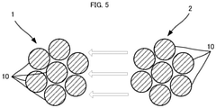
- FIG. 5 is a cross-sectional view illustrating a state of the electric field when the yarn 1 and the yarn 2 are brought close to each other.
- the surface In the yarn 1 alone, the surface has the positive potential and the inside has the negative potential when a tension in the axial direction is applied. In the yarn 2 alone, the surface has the negative potential and the inside has the positive potential when the tension in the axial direction is applied.
- the electric field directed mainly from the outside to the inside of the yarn 1 is generated, and in the cross-section of the yarn 2, the electric field directed mainly from the inside to the outside of the yarn 2 is generated.
- these electric fields leak out into the air and are synthesized, and the electric field is generated between the yarn 1 and the yarn 2 due to a potential difference between the yarn 1 and the yarn 2.
- the electric field is generated between the yarn 1 and the object approaching. Even when the yarn 2 and the object having the predetermined potential such as the human body approach each other, the electric field is generated between the yarn 2 and the object approaching.
- the electric field as described above exerts an antibacterial effect of suppressing growth of, for example, viruses, bacteria, fungi, archaea, and microorganisms such as mites and fleas.
- the yarn 1 or the yarn 2 may directly exhibit the antibacterial effect or a sterilizing effect even by this current.
- the antibacterial effect or the sterilizing effect may be indirectly exhibited by an active oxygen species in which oxygen contained in the moisture is changed by an action of current or voltage, a radical species generated by an interaction with an additive contained in the fiber or a catalytic action, or other antibacterial chemical species (amine derivative or the like).
- oxygen radicals may be generated in cells of bacteria by a stress environment due to a presence of the electric field or the current. As the radical, generation of a superoxide anion radical (active oxygen) or a hydroxy radical is considered.
- the conventional materials having antibacterial properties such as drugs
- their effects do not last for a long time.
- the conventional materials having antibacterial properties may cause an allergic reaction due to the drug or the like.
- the antibacterial effect of the yarn of the present embodiment lasts longer than the antibacterial effect by the drug or the like.
- the yarn of the present embodiment is less likely to cause the allergic reaction than the drug.
- the piezoelectric constant of polylactic acid does not vary with time and is extremely stable as described above, the antibacterial effect of the yarn is also stably exhibited for a long time.
- the yarn 1 or the yarn 2 can charge other substances by the generated potential.
- the yarn 1 or the yarn 2 can adsorb a substance by the generated potential.
- the yarn 1 since the positive potential is generated on the surface of the yarn 1, the yarn 1 can adsorb the substance having the negative potential. Since the negative potential is generated on the surface of the yarn 2, the yarn 2 can adsorb the substance having the positive potential.
- the yarn 1 or the yarn 2 can efficiently adsorb the substance by constituting a filter.
- a filter is suitable for a mask or an air purifier.
- the substance can be more efficiently adsorbed by positively or negatively charging the substance with the yarn 1 or the yarn 2 as a pre-filter of a preceding stage, and using the yarn 1 or the yarn 2 which generates a potential of opposite polarity as the filter of a subsequent stage.
- the substance may be positively or negatively charged with the yarn 1 or the yarn 2 as the pre-filter of the preceding stage, and an electret filter having the potential of opposite polarity may be used as the filter of the subsequent stage.
- the yarn of the present invention includes the fiber that generates the potential on the surface by the energy from the outside, and generates the potential of 0.1 V or more on the surface of the yarn by measuring under the following conditions (a) to (d).
- the yarn of the present invention can exhibit a desired effect by generating the potential defined under such conditions.
- strain of the yarn is preferably 0.1% or more.
- the strain is more preferably 0.5% or more.
- the potential of the surface is preferably 0.3 V or more, and more preferably 1.0 V or more.
- the thickness (single fiber fineness) of the yarn is preferably 0.005 to 10 dtex.
- the single fiber fineness is small, the number of filaments is too large, and fluffing tends to occur.
- the single fiber fineness is large and the number of filaments is too small, texture is impaired.
- the single fiber fineness referred to herein is the single fiber fineness of one twisted yarn. Even when the twisted yarn is further combined, it means the single fiber fineness of one twisted yarn before being combined.
- fiber strength of the yarn is preferably 1 to 5 cN/dtex.
- the fiber strength is more preferably 2 to 10 cN/dtex, still more preferably 3 to 10 cN/dtex, and most preferably 3.5 to 10 cN/dtex.
- elongation of the yarn is preferably 10 to 50%.
- the crystallinity of polylactic acid is preferably 15 to 55%.
- the piezoelectricity derived from polylactic acid crystal is increased, and polarization due to the piezoelectricity of the polylactic acid can be more effectively generated.
- the yarn of Example 1 to 3 is a twisted yarn using polylactic acid having a crystallinity of 45%, a crystal size of 12 nm, and an orientation of 79%, and using 84 dtex-24 filament.
- the yarn of Example 1 to 3 is formed by covering the core material made of conductive fibers with a filament of polylactic acid. Further, the core material is grounded. Therefore, the inner side of the yarn of Example 1 to 3 has a potential of 0 V.
- Example 1 the number of twists is 500 T/m, in Example 2, the number of twists is 1150 T/m, and in Example 3, the number of twists is 3000 T/m.
- the average twist angle is 10°
- the average twist angle is 28°
- the average twist angle is 47°.
- Table 1 shows the results of sandwiching both ends of the yarn of Examples 1 to 3 with rigid jigs, stretching the yarn of 40 mm to 40.2 mm, neutralizing the yarn with an ionizer, then stretching the yarn by 0.5% (40.2 mm to 40.4 mm) in the axial direction, and measuring the potential on the surface of the yarn with the electric force microscope. Potential values shown in Table 1 are positive or negative peak values. [Table 1] 40.2 ⁇ 40.4 mm (0.5%) stretch Twist direction 500 times 1150 times 3000 times S -0.15V -1.22V -0.35V Z 0.12V 0.96V 0.40V
- the S yarn of Example 1 generates a potential of -0.15 V.
- the Z yarn of Example 1 generates a potential of 0.12 V.
- the S yarn of Example 2 generates a potential of -1.22 V.
- the Z yarn of Example 2 generates a potential of 0.96 V.
- the S yarn of Example 3 generates a potential of -0.35 V.
- the Z yarn of Example 3 generates a potential of 0.40 V.
- Table 2 shows the results of measuring the surface potential of the yarn with the electric force microscope when the yarn was further stretched and contracted to 0.25% (stretched and contracted between 40.4 mm and 40.5 mm) in the axial direction after the measurement under the conditions of Table 1 above.
- the negative potential is generated on the surface
- the positive potential is generated on the surface
- the Z yarn is stretched
- the positive potential is generated on the surface
- the Z yarn is contracted
- the negative potential is generated on the surface. Therefore, when the yarn is stretched and contracted, the positive potentials and the negative potentials are alternately generated.
- Values of the surface potential shown in Table 2 are differences between minimum values and maximum values (differences between a peak value to a peak value).
- the S yarn of Example 1 generates a potential of 0.28 V.
- the Z yarn of Example 1 generates a potential of 0.33 V.
- the S yarn of Example 2 generates a potential of 2.83 V.
- the Z yarn of Example 2 generates a potential of 2.42 V.
- the S yarn of Example 3 generates a potential of 0.80 V.
- the Z yarn of Example 3 generates a potential of 0.75 V.
- the yarn of the present invention can exhibit the desired effect by generating the potential (0.1 V or more) defined under the above conditions (a) to (d).
- the average twist angle is preferably 10° to 50°. Further, in the above measurement results, since the highest potential is generated when the twist angle is 30°, it can be said that the average twist angle is more preferably 20° to 40°.
- the yarn of the present invention can be used by combining a plurality of types of twisted yarns as necessary.
- an S-twisted yarn mainly using poly-L-lactic acid and a Z-twisted yarn mainly using poly-L-lactic acid can be used.
- the fabric of the present invention includes, for example, the yarn 1 or the yarn 2 described above.
- the fabric refers to a textile product such as a woven fabric, a knitted fabric, a braided fabric, a nonwoven fabric, and a lace.
- Each of the yarns constituting the fabric may generate a potential of 0.1 V or more on the surface under the above-described conditions (a) to (d), but the fabric itself of the present invention may generate a potential of 0.1 V or more on the surface of the fabric by measurement under the following conditions (a) to (d).
- the fabric of the present invention can also exhibit the desired effect by generating the potential defined under such conditions.
- strain of the fabric is preferably 0.1% or more.
- the strain is more preferably 0.5% or more.
- the potential of the surface is preferably 0.3 V or more, and more preferably 1.0 V or more.
- the thickness (single fiber fineness) of the fiber is preferably 0.005 to 10 dtex.
- the fiber strength is preferably 1 to 5 cN/dtex.
- the fiber strength is more preferably 2 to 10 cN/dtex, still more preferably 3 to 10 cN/dtex, and most preferably 3.5 to 10 cN/dtex.
- the elongation of the fiber is preferably 10 to 50%.
- the crystallinity of the polylactic acid is preferably 15 to 55%.
- the average twist angle of the twisted yarn is preferably 10 to 50°, and the average twist angle is more preferably 20 to 40°.
- a basis weight of the fabric is preferably 20 to 200 g/m 2 , and a porosity is preferably 50 to 95%. Further, when the fabric is used as the filter, the filter preferably has a collection rate of fine particles of 0.3 ⁇ m of 40% or more and a pressure loss of less than 250 Pa at an air velocity of 5.1 cm/sec or more in order to improve collection performance and collection stability.
- the fabric of the present invention is applicable to various products such as clothing and medical members.
- the fabric of the present invention can be applied to underwear (in particular, socks), towels, insoles for shoes and boots, sportswear in general, hats, bedding (including beds, mattresses, sheets, pillows, pillows covers, and the like), toothbrushes, flosses, various filters (filter and the like of water purifier, air conditioner, or air purifier), stuffed animals, pet-related products (mat for pet, clothing for pet, and inner of clothing for pet), various mat products (foot, hand, toilet seat, or the like), curtains, kitchen utensils (sponges, cloths, or the like), seats (seats of cars, trains, airplanes or the like), cushioning materials for motorbike helmets and exterior materials thereof, sofas, bandages, gauzes, masks, sutures, clothes for doctors and patients, supporters, sanitary items, sporting goods (inner of wear and glove, gauntlet used in martial arts, or the like), packaging materials, and the like.
- the socks (or supporters) always expand and contract along joints due to movement such as walking, and thus polarization occurs frequently.
- the socks absorb moisture such as sweat and serve as a hotbed for the growth of bacteria, but the fabric of the present invention can suppress the growth of the bacteria, and thus produces a remarkable effect as a bacterium-countermeasure application.
- the yarn of the present invention may be a non-twisted yarn or a false twisted yarn.
- the yarn constituting the fabric of the present invention may also be the non-twisted yarn or the false twisted yarn.
- Various desired effects such as the antibacterial effect can be exhibited as long as the fiber is provided which generates the potential on the surface by the energy from the outside, and the potential of 0.1 V or more is generated under the above conditions.
Landscapes
- Engineering & Computer Science (AREA)
- Textile Engineering (AREA)
- Mechanical Engineering (AREA)
- Manufacturing & Machinery (AREA)
- Chemical & Material Sciences (AREA)
- Chemical Kinetics & Catalysis (AREA)
- General Chemical & Material Sciences (AREA)
- Yarns And Mechanical Finishing Of Yarns Or Ropes (AREA)
- Treatment Of Fiber Materials (AREA)
- Woven Fabrics (AREA)
- Knitting Of Fabric (AREA)
Applications Claiming Priority (2)
| Application Number | Priority Date | Filing Date | Title |
|---|---|---|---|
| JP2019099434 | 2019-05-28 | ||
| PCT/JP2020/020041 WO2020241432A1 (fr) | 2019-05-28 | 2020-05-21 | Fil et tissu |
Publications (2)
| Publication Number | Publication Date |
|---|---|
| EP3960919A1 true EP3960919A1 (fr) | 2022-03-02 |
| EP3960919A4 EP3960919A4 (fr) | 2022-12-28 |
Family
ID=73552210
Family Applications (1)
| Application Number | Title | Priority Date | Filing Date |
|---|---|---|---|
| EP20814268.7A Pending EP3960919A4 (fr) | 2019-05-28 | 2020-05-21 | Fil et tissu |
Country Status (6)
| Country | Link |
|---|---|
| US (1) | US20220074086A1 (fr) |
| EP (1) | EP3960919A4 (fr) |
| JP (2) | JPWO2020241432A1 (fr) |
| CN (1) | CN113891963A (fr) |
| TW (1) | TWI780437B (fr) |
| WO (1) | WO2020241432A1 (fr) |
Families Citing this family (3)
| Publication number | Priority date | Publication date | Assignee | Title |
|---|---|---|---|---|
| JP2022161847A (ja) * | 2021-04-08 | 2022-10-21 | 株式会社村田製作所 | 電位測定装置 |
| US20240018697A1 (en) * | 2022-07-15 | 2024-01-18 | Wetsox, LLC | Twisted yarns and methods of manufacture thereof |
| US12053553B1 (en) * | 2023-05-24 | 2024-08-06 | A-Top Health Biotech Co., Ltd. | Surgical thread, cosmetic treatment and manufacturing method thereof |
Family Cites Families (22)
| Publication number | Priority date | Publication date | Assignee | Title |
|---|---|---|---|---|
| JP2681032B2 (ja) * | 1994-07-26 | 1997-11-19 | 山形大学長 | 強誘電性高分子単結晶、その製造方法、およびそれを用いた圧電素子、焦電素子並びに非線形光学素子 |
| JP4304088B2 (ja) * | 2004-01-26 | 2009-07-29 | 株式会社マルゼン | 導線性繊維縫製生地 |
| JP2011074527A (ja) * | 2009-09-30 | 2011-04-14 | Teijin Fibers Ltd | 織ネーム |
| US20150280102A1 (en) * | 2012-10-12 | 2015-10-01 | Kansai University | Piezoelectric element |
| CN203904572U (zh) * | 2014-01-26 | 2014-10-29 | 国家纳米科学中心 | 一种纱线和无源发光织物 |
| KR102480632B1 (ko) * | 2015-03-23 | 2022-12-26 | 삼성디스플레이 주식회사 | 압전 소자 및 이를 이용한 압전 센서 |
| PL3096368T3 (pl) * | 2015-05-22 | 2017-12-29 | Sanko Tekstil Isletmeleri San. Ve Tic. A.S. | Struktura przędzy kompozytowej |
| CN116456804A (zh) * | 2015-12-25 | 2023-07-18 | 三井化学株式会社 | 压电基材、压电机织物、压电针织物、压电装置、力传感器、致动器及生物体信息获取装置 |
| JP6771310B2 (ja) * | 2016-05-06 | 2020-10-21 | 帝人フロンティア株式会社 | カバリング糸状圧電素子を用いたデバイス |
| WO2017212523A1 (fr) * | 2016-06-06 | 2017-12-14 | 株式会社村田製作所 | Fil antibactérien piézoélectrique, tissu antibactérien, vêtement, élément médical, fil bioactif piézoélectrique et fil piézoélectrique pour adsorption de substance |
| WO2017213108A1 (fr) * | 2016-06-06 | 2017-12-14 | 三井化学株式会社 | Matériau de base piézoélectrique, tissu tissé piézoélectrique, tissu tricoté piézoélectrique, dispositif piézoélectrique, capteur de force et actionneur |
| JP6919343B2 (ja) * | 2016-06-06 | 2021-08-18 | 株式会社村田製作所 | 布、衣料、および医療部材 |
| JP6785618B2 (ja) * | 2016-10-28 | 2020-11-18 | 帝人株式会社 | 圧電素子に用いる構造体およびそれを用いたデバイス |
| CN109844971B (zh) * | 2016-10-28 | 2023-07-28 | 帝人株式会社 | 用于压电元件的构造体、线绳状压电元件、布帛状压电元件和使用它们的设备 |
| JP6789312B2 (ja) * | 2016-11-18 | 2020-11-25 | 三井化学株式会社 | 圧電基材、センサー、アクチュエーター、生体情報取得デバイス、及び圧電繊維構造体 |
| CN110088366B (zh) * | 2016-12-20 | 2022-02-11 | 株式会社村田制作所 | 抗菌纤维 |
| JP6428979B1 (ja) * | 2017-05-19 | 2018-11-28 | 株式会社村田製作所 | 抗菌糸、シート、およびシートカバー |
| WO2018221332A1 (fr) * | 2017-05-30 | 2018-12-06 | 帝人フロンティア株式会社 | Fil de génération de charge électrique antibactérienne, procédé de fabrication de fil de génération de charge électrique antibactérienne, et tissu antibactérien |
| JP6784334B2 (ja) * | 2017-07-28 | 2020-11-11 | 株式会社村田製作所 | 抗菌糸及び抗菌繊維製品 |
| WO2019069660A1 (fr) * | 2017-10-05 | 2019-04-11 | 株式会社村田製作所 | Fibres piézoélectriques |
| JP6521208B1 (ja) * | 2017-10-17 | 2019-05-29 | 株式会社村田製作所 | 抗菌糸及び抗菌ファブリック |
| WO2019077957A1 (fr) * | 2017-10-17 | 2019-04-25 | 株式会社村田製作所 | Filtre et dispositif de climatisation |
-
2020
- 2020-05-21 WO PCT/JP2020/020041 patent/WO2020241432A1/fr unknown
- 2020-05-21 JP JP2021522281A patent/JPWO2020241432A1/ja active Pending
- 2020-05-21 CN CN202080039521.1A patent/CN113891963A/zh active Pending
- 2020-05-21 EP EP20814268.7A patent/EP3960919A4/fr active Pending
- 2020-05-26 TW TW109117448A patent/TWI780437B/zh active
-
2021
- 2021-11-19 US US17/530,985 patent/US20220074086A1/en active Pending
-
2024
- 2024-02-21 JP JP2024024331A patent/JP2024045680A/ja active Pending
Also Published As
| Publication number | Publication date |
|---|---|
| WO2020241432A1 (fr) | 2020-12-03 |
| JP2024045680A (ja) | 2024-04-02 |
| TW202106937A (zh) | 2021-02-16 |
| CN113891963A (zh) | 2022-01-04 |
| TWI780437B (zh) | 2022-10-11 |
| US20220074086A1 (en) | 2022-03-10 |
| JPWO2020241432A1 (ja) | 2021-10-21 |
| EP3960919A4 (fr) | 2022-12-28 |
Similar Documents
| Publication | Publication Date | Title |
|---|---|---|
| CN109312500B (zh) | 用于应对菌的电荷产生纱线、用于应对菌的布、布、衣料、医疗部件、生物体作用电荷产生纱线、以及物质吸附用电荷产生纱线 | |
| US11071933B2 (en) | Filter and air-conditioning device | |
| US20220074086A1 (en) | Yarn and fabric | |
| JP6428979B1 (ja) | 抗菌糸、シート、およびシートカバー | |
| CN110709544B (zh) | 用于应对菌的电荷产生纱线、用于应对菌的电荷产生纱线的制造方法和抗菌性布帛 | |
| US11326279B2 (en) | Antibacterial yarn and antibacterial fabric | |
| US20190281820A1 (en) | Antibacterial fiber | |
| JP7376328B2 (ja) | 抗菌撚糸、並びに抗菌撚糸を備える抗菌糸及び抗菌布 | |
| US20210057633A1 (en) | Piezoelectric fiber composite and piezoelectric clothing | |
| WO2019069660A1 (fr) | Fibres piézoélectriques | |
| JP6784334B2 (ja) | 抗菌糸及び抗菌繊維製品 | |
| WO2020111049A1 (fr) | Fil retors souple antibactérien, et fil antibactérien ainsi que tissu antibactérien dotés d'un fil retors souple antibactérien | |
| US20220228300A1 (en) | Cylindrical structure | |
| CN114051543A (zh) | 细纱、以及具备细纱的纱线和布 |
Legal Events
| Date | Code | Title | Description |
|---|---|---|---|
| STAA | Information on the status of an ep patent application or granted ep patent |
Free format text: STATUS: THE INTERNATIONAL PUBLICATION HAS BEEN MADE |
|
| PUAI | Public reference made under article 153(3) epc to a published international application that has entered the european phase |
Free format text: ORIGINAL CODE: 0009012 |
|
| STAA | Information on the status of an ep patent application or granted ep patent |
Free format text: STATUS: REQUEST FOR EXAMINATION WAS MADE |
|
| 17P | Request for examination filed |
Effective date: 20211123 |
|
| AK | Designated contracting states |
Kind code of ref document: A1 Designated state(s): AL AT BE BG CH CY CZ DE DK EE ES FI FR GB GR HR HU IE IS IT LI LT LU LV MC MK MT NL NO PL PT RO RS SE SI SK SM TR |
|
| DAV | Request for validation of the european patent (deleted) | ||
| DAX | Request for extension of the european patent (deleted) | ||
| A4 | Supplementary search report drawn up and despatched |
Effective date: 20221124 |
|
| RIC1 | Information provided on ipc code assigned before grant |
Ipc: D03D 15/00 20210101ALI20221118BHEP Ipc: D03D 1/00 20060101ALI20221118BHEP Ipc: D02G 3/36 20060101AFI20221118BHEP |
|
| STAA | Information on the status of an ep patent application or granted ep patent |
Free format text: STATUS: EXAMINATION IS IN PROGRESS |
|
| 17Q | First examination report despatched |
Effective date: 20240312 |