EP3960596A1 - Side stand structure - Google Patents
Side stand structure Download PDFInfo
- Publication number
- EP3960596A1 EP3960596A1 EP20794804.3A EP20794804A EP3960596A1 EP 3960596 A1 EP3960596 A1 EP 3960596A1 EP 20794804 A EP20794804 A EP 20794804A EP 3960596 A1 EP3960596 A1 EP 3960596A1
- Authority
- EP
- European Patent Office
- Prior art keywords
- stand
- vehicle
- rotation shaft
- connector portion
- straight line
- Prior art date
- Legal status (The legal status is an assumption and is not a legal conclusion. Google has not performed a legal analysis and makes no representation as to the accuracy of the status listed.)
- Granted
Links
- 238000003780 insertion Methods 0.000 description 18
- 230000037431 insertion Effects 0.000 description 18
- 230000002093 peripheral effect Effects 0.000 description 10
- 230000003014 reinforcing effect Effects 0.000 description 10
- 229910000831 Steel Inorganic materials 0.000 description 6
- 230000000694 effects Effects 0.000 description 6
- 239000010959 steel Substances 0.000 description 6
- 230000005540 biological transmission Effects 0.000 description 3
- 210000000078 claw Anatomy 0.000 description 3
- 239000000470 constituent Substances 0.000 description 2
- 238000010586 diagram Methods 0.000 description 2
- 230000002452 interceptive effect Effects 0.000 description 2
- 230000000149 penetrating effect Effects 0.000 description 2
- 238000002485 combustion reaction Methods 0.000 description 1
- 238000007796 conventional method Methods 0.000 description 1
- 230000002401 inhibitory effect Effects 0.000 description 1
- 238000003825 pressing Methods 0.000 description 1
- 239000000725 suspension Substances 0.000 description 1
- 238000003466 welding Methods 0.000 description 1
Images

Classifications
-
- B—PERFORMING OPERATIONS; TRANSPORTING
- B62—LAND VEHICLES FOR TRAVELLING OTHERWISE THAN ON RAILS
- B62H—CYCLE STANDS; SUPPORTS OR HOLDERS FOR PARKING OR STORING CYCLES; APPLIANCES PREVENTING OR INDICATING UNAUTHORIZED USE OR THEFT OF CYCLES; LOCKS INTEGRAL WITH CYCLES; DEVICES FOR LEARNING TO RIDE CYCLES
- B62H1/00—Supports or stands forming part of or attached to cycles
- B62H1/02—Articulated stands, e.g. in the shape of hinged arms
-
- B—PERFORMING OPERATIONS; TRANSPORTING
- B62—LAND VEHICLES FOR TRAVELLING OTHERWISE THAN ON RAILS
- B62J—CYCLE SADDLES OR SEATS; AUXILIARY DEVICES OR ACCESSORIES SPECIALLY ADAPTED TO CYCLES AND NOT OTHERWISE PROVIDED FOR, e.g. ARTICLE CARRIERS OR CYCLE PROTECTORS
- B62J45/00—Electrical equipment arrangements specially adapted for use as accessories on cycles, not otherwise provided for
- B62J45/40—Sensor arrangements; Mounting thereof
- B62J45/41—Sensor arrangements; Mounting thereof characterised by the type of sensor
- B62J45/413—Rotation sensors
-
- B—PERFORMING OPERATIONS; TRANSPORTING
- B62—LAND VEHICLES FOR TRAVELLING OTHERWISE THAN ON RAILS
- B62J—CYCLE SADDLES OR SEATS; AUXILIARY DEVICES OR ACCESSORIES SPECIALLY ADAPTED TO CYCLES AND NOT OTHERWISE PROVIDED FOR, e.g. ARTICLE CARRIERS OR CYCLE PROTECTORS
- B62J45/00—Electrical equipment arrangements specially adapted for use as accessories on cycles, not otherwise provided for
- B62J45/40—Sensor arrangements; Mounting thereof
- B62J45/42—Sensor arrangements; Mounting thereof characterised by mounting
-
- B—PERFORMING OPERATIONS; TRANSPORTING
- B62—LAND VEHICLES FOR TRAVELLING OTHERWISE THAN ON RAILS
- B62K—CYCLES; CYCLE FRAMES; CYCLE STEERING DEVICES; RIDER-OPERATED TERMINAL CONTROLS SPECIALLY ADAPTED FOR CYCLES; CYCLE AXLE SUSPENSIONS; CYCLE SIDE-CARS, FORECARS, OR THE LIKE
- B62K2202/00—Motorised scooters
Definitions
- the present invention relates to a side stand structure.
- Patent Literature 1 Japanese Patent No. 4771420
- the above-mentioned conventional technique since the side stand is supported in a state in which the vehicle body is inclined, the above-mentioned conventional technique has the following problems. That is, a stand bracket or the like that rotatably supports the side stand protrudes downward from a lower part of the vehicle body and outward in a vehicle width direction. For this reason, there are the following risks in a case in which the vehicle body is largely banked during cornering or in a case in which unevenness of a road surface is passed over. That is, there is a risk that peripheral components such as the stand bracket will unintentionally touch the ground. For this reason, further compactness around the side stand is desired.
- the present invention provides a side stand structure that can be made compact around a side stand.
- a first aspect of the present invention is a side stand structure including a side stand (20) rotatably supported by a vehicle body (11) and a stand switch (40) configured to detect a rotational position of the side stand (20), in which the side stand structure includes a rotational positioning portion (45) configured to position the stand switch (40) in a rotation direction of the side stand (20) and a connector portion (46) configured to connect wiring (H) to the stand switch (40), a first straight line (T1) connecting an axial center (p1) of a rotation shaft (35) of the side stand (20) to a positioning center (p2) of the rotational positioning portion (45) in a side view of a vehicle extends from the rotation shaft (35) side to the rotational positioning portion (45) side in one of forward and rearward directions of a longitudinal direction of the vehicle, and a second straight line (T2) in a wiring attachment and detachment direction of the connector portion (46) in the side view of the vehicle extends from the rotation shaft (35) side to the connector
- a second aspect of the present invention is that, in the first aspect described above, the first straight line (T1) in the side view of the vehicle extends from the rotation shaft (35) side to the rotational positioning portion (45) side in the forward direction of the longitudinal direction of the vehicle, and the second straight line (T2) in the side view of the vehicle extends from the rotation shaft (35) side to the connector portion (46) side in the rearward direction of the longitudinal direction of the vehicle.
- a third aspect of the present invention is that, in the second aspect described above, the side stand (20) includes a pivot portion (22) rotatably connected to the vehicle body (11), and, in an axial direction of the rotation shaft (35), an inner side surface (46d) of the connector portion (46) on an inner side in a vehicle width direction is disposed to be separated outward in the vehicle width direction from an outer side surface (22d) of the pivot portion (22) on an outer side in the vehicle width direction.
- a fourth aspect of the present invention is that, in any one of the first to third aspects described above, in the side view of the vehicle, the rotational positioning portion (45) is disposed in front of and above the rotation shaft (35), and the connector portion (46) is disposed above and behind the rotation shaft (35), the wiring (H) is attachable to and detachable from the connector portion (46) along an axis (C3) that rises rearward, and when a straight line connecting the axial center (p1) of the rotation shaft (35) to an axial center (p2) of a positioning pin (34) held by the rotational positioning portion (45) on the vehicle body (11) side in the side view of the vehicle is defined as the first straight line (T1) and a straight line along the axis (C3) of the connector portion (46) in the side view of the vehicle is defined as the second straight line (T2), a rearward inclination angle ( ⁇ 2) of the second straight line (T2) with respect to a vertical line (T3) passing through the axial center (p1) of the rotation shaft (35)
- a fifth aspect of the present invention is that, in any one of the first to fourth aspects described above, a stand bracket (30) configured to rotatably support the side stand (20) and a vehicle body frame member (14) configured to fix the stand bracket (30) are provided on the vehicle body (11) side, and the vehicle body frame member (14) includes a recessed portion (18a) that overlaps at least a part of the connector portion (46) in the side view of the vehicle.
- a sixth aspect of the present invention is that, in any one of the first to fourth aspects described above, the connector portion (46) includes a lock portion (46a) configured to lock the connector portion (46) in a coupled state, and an unlock operation portion (46b) configured to perform an unlock operation of the lock portion (46a), and the unlock operation portion (46b) is disposed on an inner side of the connector portion (46) in the vehicle width direction.
- the first straight line extending from the rotation shaft side to the rotational positioning portion side extends in one of the forward and rearward directions of the longitudinal direction of the vehicle.
- the second straight line extending from the rotation shaft side to the connector portion side extends in the other of the forward and rearward directions of the longitudinal direction of the vehicle.
- the stand switch can be disposed closer to the vehicle body in the vehicle width direction and a vertical direction. For this reason, surroundings of the side stand can be made compact, and unintended grounding of the side stand can be easily avoided by moving the side stand upward.
- the first straight line extends forward in the vehicle, and the second straight line extends rearward in the vehicle.
- the rotational positioning portion is disposed in front of the rotation shaft, and the connector portion is disposed behind the rotation shaft, the positioning pin or the like held by the rotational positioning portion on the vehicle body side is disposed in front of the rotation shaft.
- the side stand rotates between a usage position in which it extends downward from the rotation shaft and a retracted position in which it extends rearward. For this reason, by disposing the rotational positioning portion in front of the rotation shaft, the positioning pin or the like is retracted from a rotation range of the side stand.
- the rotational positioning portion and the connector portion can be disposed to be distributed in the longitudinal direction of the vehicle without obstructing the rotation range of the side stand. Further, since the connector portion that is an electrical component is disposed unilaterally rearward, it is possible to improve waterproofness and dust-proofness of the connector portion.
- the connector portion is disposed to be separated from the pivot portion outward in the vehicle width direction, it is possible to reliably prevent the side stand and the connector portion from interfering with each other when the side stand rotates.
- the wiring extending from the connector portion can be easily extended upward (on the vehicle body side), so that arrangement of the wiring can be improved and reduction in length of the wiring can be achieved.
- the vehicle body frame member since the vehicle body frame member includes the recessed portion that overlaps the connector portion, it is possible to bring the side stand, including the connector portion, closer to the vehicle body frame member. For this reason, surroundings of the side stand can be made compact, and grounding of the side stand can be easily avoided by moving the side stand upward.
- the unlock operation portion of the connector portion is disposed on the inner side of the connector portion in the vehicle width direction, it is possible to inhibit unauthorized access to the connector portion and to achieve improvement in appearance by adopting the arrangement in which the unlock operation portion is difficult to see from the outside in the vehicle width direction.
- Fig. 1 shows a unit swing type motorcycle (a scooter type vehicle) 1 as an example of a saddle-riding type vehicle of the present embodiment.
- the motorcycle 1 includes a front wheel 3 serving as a steering wheel and a rear wheel 4 serving as a driving wheel.
- the front wheel 3 is supported by a pair of left and right front forks 6 and can be steered by a handlebar 2.
- the rear wheel 4 is supported by a swing unit (a power unit) U and can be driven by an engine E.
- the swing unit U supports the rear wheel 4 serving as the driving wheel to be vertically swingable.
- the swing unit U integrally includes the engine (internal combustion engine) E serving as a drive source and, for example, a V-belt type continuously variable transmission M.
- the rear wheel 4 is supported on an output shaft of the continuously variable transmission M at a rear portion thereof.
- the rear portion of the continuously variable transmission M is supported by a vehicle body frame 11 via a rear cushion 7.
- Steering system components including the handlebar 2, the left and right front forks 6 and the front wheel 3 are steerably supported by a head pipe 12 at a front end portion of the vehicle body frame 11.
- the swing unit U and the rear wheel 4 are supported by a pivot portion (not shown) at a lower portion of the vehicle body frame 11 to be vertically swingable via a suspension link or the like.
- a front portion of the vehicle body is covered with a front cover 8, and a rear portion of the vehicle body is covered with a rear cover 9.
- a bottom floor portion 10 is provided between the front cover 8 and the rear cover 9.
- a step floor 10a on which a driver rests his or her feet is provided on an upper surface of the bottom floor portion 10.
- a seat 5 on which occupants including the driver are seated is supported on the rear cover 9.
- Reference numeral 10b in the figure indicates a pair of left and right floor side covers that wrap around and below left and right side edges of the step floor 10a.
- the vehicle body frame 11 includes the head pipe 12 located at the front end portion, a down frame 13 extending downward from the head pipe 12, a pair of left and right lower frames 14 that bend rearward from a lower end portion of the down frame 13, and a pair of left and right rear frames 15 extending to appropriately bend upward and rearward from rear end portion of the lower frames 14.
- the pivot portion that supports a front end portion of the swing unit U is provided in the vicinity of the rear end portions of the left and right lower frames 14.
- a foldable type side stand 20 is attached to the left lower frame (vehicle body frame member) 14 of the vehicle body frame 11.
- the side stand 20 supports the vehicle body of the motorcycle 1 in an upright and leftwardly inclined state.
- the side stand 20 is rotatably supported by a stand bracket 30 fixed to the left lower frame 14.
- the side stand 20 is rotatable between a retracted position at which a tip side (grounding side) thereof is flipped up behind a rotation shaft 35 (which may be indicated by an axis C1 in the figure), and a usage position (standing position) in which the tip side is extended below the rotation shaft 35.
- the side stand 20 at the usage position is shown by a chain line.
- the side stand 20 integrally includes, for example, a stand bar 21 made of a straight steel pipe, a pivot portion 22 that is provided on one end side (a base end side or rotation shaft 35 side) of the stand bar 21 and is rotatably connected to the vehicle body side, and a grounding portion 23 that is provided on the other end side (the tip side or grounding side) of the stand bar 21 and forms a grounding surface for supporting the vehicle body.
- the pivot portion 22 has a bifurcated shape that sandwiches a flat plate-shaped stand connection portion 31a of the stand bracket 30 in a plate thickness direction.
- the pivot portion 22 includes a pair of two plate portions 22a and 22b.
- the plate portions 22a and 22b are provided parallel to each other at intervals in the plate thickness direction of the stand connection portion 31a.
- a groove portion 22c into which the stand connection portion 31a can be relatively rotatably inserted is formed between the plate portions 22a and 22b.
- Shaft insertion holes 22a1 and 22b 1 through which the rotation shaft 35 is inserted are formed coaxially with each other in both plate portions 22a and 22b.
- the side stand 20 inserts the stand connection portion 31a of the stand bracket 30 into the groove portion 22c of the pivot portion 22. In this state, the rotation shaft 35 penetrating the pivot portion 22 and the stand connection portion 31a is attached. As a result, the side stand 20 is rotatably connected to and supported by the stand bracket 30 via the rotation shaft 35.
- the rotation shaft 35 is inclined upward such that a portion thereof on an outer side in the vehicle width direction is located on an upper side.
- the side stand 20 is protruded outward in the vehicle width direction.
- the side stand 20 is inhibited from protruding outward in the vehicle width direction.
- the side stand 20 in the standing position protruding outward in the vehicle width direction provides the following effects. That is, the grounding portion 23 is disposed on an outer side in the vehicle width direction to easily support the vehicle body of the motorcycle 1.
- the rotation shaft 35 is also inclined in a longitudinal direction such that a portion thereof on the outer side in the vehicle width direction is located further forward.
- the line C1 in the figure indicates a central axis of the rotation shaft 35.
- the side stand 20 and its peripheral components may be unintentionally grounded. This grounding occurs in a case in which the vehicle body is largely banked during cornering or in a case in which it passes over unevenness on a road surface.
- an attachment position of the side stand 20 is preferably located as high as possible.
- a locking hook 26 for locking one end portion of a stand spring (tensile coil spring) 25 is provided on the tip side of the side stand 20.
- the locking hook 26 protrudes outward in the vehicle width direction from an intermediate portion of the stand bar 21 in a longitudinal direction thereof, and then bends toward the tip side of the stand bar 21.
- the locking hook 26 bends toward the tip side of the stand bar 21 and then extends linearly to the grounding portion 23, and a tip portion thereof is welded to the grounding portion 23.
- An extension portion of the locking hook 26 to the grounding portion 23 protrudes outward in the vehicle width direction on the tip side of the stand bar 21 to be a footrest portion 26a.
- the footrest portion 26a enables a rotation operation of the side stand 20 performed by a user's foot.
- the left lower frame 14 of the vehicle body frame 11 is a press frame.
- the press frame is formed by integrally combining a plurality of press frame bodies.
- the left lower frame 14 includes an outer frame body 16a on an outer side in the vehicle width direction and an inner frame body 16b on an inner side in the vehicle width direction.
- Both of the frame bodies 16a and 16b are formed by, for example, pressing a steel plate.
- Both of the frame bodies 16a and 16b join joining flanges 16a1 and 16b1 provided on outer peripheral portions thereof or the like by spot welding or the like. As a result, both of the frame bodies 16a and 16b form the left lower frame 14 having a closed cross-sectional structure.
- the left lower frame 14 is provided with a stand attachment portion 18 for attaching the site stand.
- the stand attachment portion 18 includes a reinforcing bracket 19 welded and fixed to the left lower frame 14, and the stand bracket 30 welded and fixed to the reinforcing bracket 19.
- the reinforcing bracket 19 and the stand bracket 30 are included in the configuration of the vehicle body frame 11.
- the reinforcing bracket 19 is formed to be bent in a substantially V shape when viewed in the longitudinal direction to straddle the left lower frame 14 from below.
- the reinforcing bracket 19 includes an outer plate portion 19a, an inner plate portion 19b, and an inclined plate portion 19c.
- the outer plate portion 19a is disposed along an outer surface of the left lower frame 14 in the vehicle width direction and is joined to the outer surface.
- the inner plate portion 19b is disposed along an inner side surface of the left lower frame 14 in the vehicle width direction and is joined to the inner side surface.
- the inclined plate portion 19c is inclined and extends below the outer plate portion 19a toward a lower end portion 19d of the bracket to be located inward in the vehicle width direction toward a lower side thereof.
- the lower end portion 19d of the bracket has a U shape when viewed in the longitudinal direction.
- a lower end portion of the inner plate portion 19b is connected to an upper end portion of the lower end portion 19d of the bracket on an inner side thereof in the vehicle width direction.
- a lower end portion of the inclined plate portion 19c is connected to an upper end portion of the lower end portion 19d of the bracket on an outer side thereof in the vehicle width direction.
- a portion of the left lower frame 14 to which the reinforcing bracket 19 is joined is a portion of the outer frame body 16a to which the outer plate portion 19a is joined.
- a joggle (hereinafter, referred to as a recessed portion 18a) that changes the outer surface inward in the vehicle width direction is formed.
- the recessed portion 18a is located at a position overlapping a connector portion 46, which will be described later, in a side view of the vehicle.
- the recessed portion 18a is also an avoidance portion that avoids the inner side of the connector portion 46 in the vehicle width direction.
- the stand bracket 30 includes a bracket base 32 joined to the reinforcing bracket 19, and a connecting plate 31 that is joined to and held by the bracket base 32 to form the stand connection portion 31a.
- the bracket base 32 includes a joint plate portion 32a and a front end plate portion 32b.
- the joint plate portion 32a bends along the outer surface in the vehicle width direction at each of the inclined plate portion 19c and the lower end portion 19d of the bracket of the reinforcing bracket 19.
- the front end plate portion 32b extends to bend downward in a direction orthogonal to the inclined plate portion 19c outward from a front end portion of the joint plate portion 32a outward in the vehicle width direction.
- the front end plate portion 32b extends outward in the vehicle width direction from a stand switch 40, which will be described later, and inhibits the influence of disturbance from an outer side in the vehicle width direction on surroundings of the stand switch 40.
- the connecting plate 31 is disposed to be orthogonal to the inclined plate portion 19c.
- the connecting plate 31 is inclined to position both surfaces thereof in the plate thickness direction on a lower side toward the outer side in the vehicle width direction.
- the connecting plate 31 forms the stand connection portion 31a into which the pivot portion 22 of the side stand 20 is fitted.
- the connecting plate 31 is formed of a steel plate thicker than the bracket base 32.
- the bracket base 32 is made of a steel plate thicker than the reinforcing bracket 19.
- the reinforcing bracket 19 is made of a steel plate thicker than the outer frame body 16a and the inner frame body 16b.
- the stand attachment portion 18 is not limited to the above configuration.
- the vehicle body frame 11 may be made of a steel pipe
- the stand bracket 30 may be an integrally formed product
- the stand bracket 30 may be configured to be detachably fixed to the vehicle body frame 11 by bolt-fastening or the like.
- the stand connection portion 31a forms a shaft insertion hole 31b (see Fig. 5 ) penetrating in the plate thickness direction at a substantially central portion thereof in a plan view.
- the shaft insertion hole 3 1b has the following arrangement in a state in which the connecting plate 31 is inserted into the groove portion 22c of the pivot portion 22.
- the shaft insertion hole 31b is coaxially disposed with the shaft insertion holes 22a1 and 22b1 provided in the pair of plate portions 22a and 22b of the pivot portion 22.
- the rotation shaft 35 is configured as a so-called stepped bolt 36.
- the stepped bolt 36 is removably inserted from an outer side in the vehicle width direction into the insertion holes 22a1, 22b1, and 31b of the pivot portion 22 and the stand connection portion 31a.
- the stepped bolt 36 includes a head portion 36a located on an outer side in the vehicle width direction, a shaft portion 36b connected to an inner side of the head portion 36a in the vehicle width direction, and a screw shaft 36c protruding inward in the vehicle width direction of the pivot portion 22.
- the shaft insertion hole 22a1 of the plate portion 22a on an outer side of the pivot portion 22 in the vehicle width direction and the shaft insertion hole 31b of the stand connection portion 31a have the same diameter.
- the shaft portion 36b of the stepped bolt 36 can be inserted into each of the shaft insertion holes 22a1 and 31b.
- the shaft insertion hole 22b1 of the plate portion 22b on the inner side of the pivot portion 22 in the vehicle width direction is set to the following diameter.
- the shaft insertion hole 22b1 has a smaller diameter than each of the shaft insertion holes 22a1 and 3 1b of the plate portion 22a and the stand connection portion 31a on the outer side of the pivot portion 22 in the vehicle width direction.
- the screw shaft 36c of the stepped bolt 36 can be inserted into the shaft insertion hole 22b1, but cannot be inserted into the shaft portion 36b.
- a circumferential edge of the shaft insertion hole 22b1 on the outer side in the vehicle width direction (on the stand connection portion 31a side) is a seating surface that abuts a tip surface of the shaft portion 36b.
- the shaft portion 36b has a larger diameter than the screw shaft 36c.
- the shaft portion 36b of the stepped bolt 36 is inserted into the shaft insertion holes 22a1 and 31b of the plate portion 22a of the pivot portion 22 on the outer side in the vehicle width direction and the stand connection portion 31a.
- the shaft portion 36b causes the tip surface to abut a peripheral edge portion of the shaft insertion hole 22b1 of the plate portion 22b on the inner side in the vehicle width direction.
- a nut 37 is screwed and tightened to the screw shaft 36c protruding inward from the pivot portion 22 in the vehicle width direction.
- the stepped bolt 36 is fixed to the plate portion 22b on the inner side in the vehicle width direction.
- the pivot portion 22 is rotatably supported on and connected to the stand connection portion 31a via the stepped bolt 36.
- a stepped front lower stopper portion 33a that defines the standing position of the side stand 20 is formed at a front lower portion of the connecting plate 31.
- the front lower stopper portion 33a abuts one end side of the pivot portion 22 in a rotation direction thereof from behind to define the standing position of the side stand 20.
- a stepped rear upper stopper portion 33b that defines the retracted position of the side stand 20 is formed on a rear upper portion of the connecting plate 31.
- the rear upper stopper portion 33b abuts the other end side of the pivot portion 22 in the rotation direction from below to define the retracted position of the side stand 20.
- a locking pin 34 for locking the other end portion of the stand spring (tensile coil spring) 25 is provided to protrude from a front upper portion of the connecting plate 31.
- the locking pin 34 is provided, for example, in parallel with the rotation shaft 35.
- the stand spring 25 is provided to stretch between the locking hook 26 of the side stand 20 and the locking pin 34 of the stand connection portion 31a.
- the stand spring 25 holds a rotational position of the side stand 20 in the standing position or the retracted position due to its own tension.
- a line C2 in the figure indicates a central axis of the locking pin 34.
- the stand switch 40 for detecting the rotational position of the side stand 20 is provided on the outer side of the pivot portion 22 in the vehicle width direction.
- the stand switch 40 is a rotary switch provided coaxially with the rotation shaft 35.
- the stand switch 40 detects whether the side stand 20 is in the usage position or the retracted position and outputs a corresponding electric signal.
- This electric signal is sent to an engine control unit (not shown) and used for various controls.
- This control is, for example, control for making it impossible to start the engine E when the side stand 20 is in the usage position while the engine E is stopped. Further, for example, the control is control for stopping the engine E when the side stand 20 rotates from the retracted position to the usage position while the engine E is in operation.
- the stand switch 40 includes a rotor 41 and a case 42.
- the rotor 41 is provided to be rotatable integrally with the side stand 20.
- the case 42 accommodates the rotor 41 and is provided to be rotatable relative to the side stand 20.
- the rotor 41 is disposed on an outer side of the head portion 36a of the stepped bolt 36 in the vehicle width direction.
- a switch attachment bolt 43 coaxial with the stepped bolt 36 can be inserted into the rotor 41.
- the switch attachment bolt 43 penetrates the rotor 41 and is screwed and tightened to a screw hole 36d provided to protrude on the head portion 36a side of the stepped bolt 36.
- the rotor 41 can rotate integrally with the stepped bolt 36 and thus the side stand 20.
- the case 42 has a circular shape when viewed in the axial direction of the rotation shaft 35.
- the case 42 has a cup shape that covers the rotor 41 from an outer side in the vehicle width direction.
- the case 42 is disposed close to the plate portion 22a on the outer side of the pivot portion 22 in the vehicle width direction via a thrust washer 42a or the like. In this state, detachment of the case 42 outward in the vehicle width direction is restricted by a large-diameter washer 43a used for a seating surface of the switch attachment bolt 43. As a result, the case 42 is attached to the outer side of the pivot portion 22 in the vehicle width direction.
- the locking pin 34 for locking the stand spring 25 is located in front of and above the case 42.
- a locking claw portion 42b is provided to protrude from a front upper portion of the case 42 toward an outer peripheral side (outer side in a radial direction) of the case 42.
- the locking claw portion 42b forms a U-shaped locking groove 42c that opens to the outer peripheral side of the case 42.
- the locking pin 34 can be engaged into the locking groove 42c.
- the locking claw portion 42b and the locking pin 34 constitute a rotational positioning portion 45 that performs positioning of the case 42 in the rotation direction of the side stand 20.
- intersection points are intersection points between the central axes C1 and C2 of the rotation shaft 35 and the locking pin 34 and the outer surface of the connecting plate 31 (a plane orthogonal to the rotation shaft 35) on the outer side in the vehicle width direction.
- these intersection points are defined as axial centers p1 and p2 of the rotation shaft 35 and the locking pin 34.
- a straight line connecting the axial center p1 of the rotation shaft 35 to the axial center p2 of the locking pin 34 in the side view of the vehicle is defined as a first straight line T1.
- the axial center p2 corresponds to a positioning center of the rotational positioning portion 45.
- the connector portion 46 is disposed on a rear upper side of the case 42.
- the connector portion 46 makes it possible to connect electric wiring (harness) H extending from the vehicle body side to the stand switch 40.
- the connector portion 46 includes a terminal portion 47 and a coupler 48.
- the terminal portion 47 is provided to protrude from a rear upper portion of the case 42 toward the outer peripheral side of the case 42.
- the coupler 48 is externally fitted by inserting the terminal portion 47 thereinto from the outer peripheral side of the case 42.
- Aline C3 in Fig. 3 indicates a central axis in an insertion and removal direction (wiring attachment and detachment direction) of the coupler 48 in the connector portion 46.
- the insertion and removal direction of the coupler 48 is a direction parallel to a plane orthogonal to the rotation shaft 35.
- a straight line along the central axis C3 in the side view of the vehicle is defined as a second straight line T2.
- the rotational positioning portion 45 and the connector portion 46 are disposed with respect to the rotation shaft 35 of the side stand 20 as follows. That is, the rotational positioning portion 45 and the connector portion 46 are disposed to be distributed on front and rear side in the longitudinal direction of the vehicle. In the side view of the vehicle, the rotational positioning portion 45 is disposed in front of the rotation shaft 35. Further, the connector portion 46 is disposed behind the rotation shaft 35.
- the line T3 in Fig. 6 indicates a vertical line passing through the axial center p1 of the rotation shaft 35 in the side view of the vehicle.
- a straight line connecting the axial center p1 of the rotation shaft 35 to the positioning center p2 of the rotational positioning portion 45 is defined as the first straight line T1.
- the first straight line T1 extends diagonally from the rotation shaft 35 side to the rotational positioning portion 45 side toward a front upper side.
- the straight line in the wiring attachment and detachment direction (central axis C3) of the connector portion 46 is defined as the second straight line T2.
- the second straight line T2 extends diagonally from the rotation shaft 35 side to the connector portion 46 side toward a rear upper side.
- the first straight line T1 and the second straight line T2 are disposed in a V shape at a relative angle to intersect each other.
- the rotational positioning portion 45 is disposed on the front side of the vehicle and the connector portion 46 is disposed on the rear side of the vehicle with reference to the rotation shaft 35 of the stand switch 40. That is, the rotational positioning portion 45 and the connector portion 46 of the stand switch 40 are dispersedly disposed in the longitudinal direction of the vehicle.
- a rearward inclination angle ⁇ 2 of the second straight line T2 with respect to the vertical line T3 passing through the axial center p1 of the rotation shaft 35 is set as follows. That is, the inclination angle ⁇ 2 is set to be smaller than a forward inclination angle ⁇ 1 of the first straight line T1 with respect to the vertical line T3 (that is, to be more upright). This makes it easier to extend the wiring H extending from the connector portion 46 upward (toward the vehicle body side). Accordingly, arrangement of the wiring H can be improved and reduction in length of the wiring H can be achieved.
- an inner side surface 46d of the connector portion 46 on the inner side in the vehicle width direction is located outward in the vehicle width direction from the outer side surface 22d of the pivot portion 22 on the outer side in the vehicle width direction. That is, the connector portion 46 is offset outward in the vehicle width direction with respect to the case 42 in the axial direction of the rotation shaft 35.
- the central axis C3 of the connector portion 46 is offset outward in the vehicle width direction with respect to a height center of the case 42 (indicated by a line T4 in the figure).
- the inner side surface 46d of the connector portion 46 on the inner side in the vehicle width direction is separated from the outer side surface 22d of the pivot portion 22 on the outer side in the vehicle width direction by an interval k outward in the vehicle width direction.
- the inner side surface 46d of the connector portion 46 on the inner side in the vehicle width direction is disposed outward in the vehicle width direction from the outer side surface 22d of the pivot portion 22 of the side stand 20 on the outer side in the vehicle width direction.
- the connector portion 46 of the stand switch 40 includes a lock portion 46a.
- the lock portion 46a restricts removal of the coupler 48 from the terminal portion 47 in a connected state in which the terminal portion 47 and the coupler 48 are fitted to each other.
- the connector portion 46 includes a unlock operation portion 46b that enables the coupler 48 to perform an unlock operation of the removal restriction of the lock portion 46a.
- the unlock operation portion 46b is disposed on the inner side of the connector portion 46 in the vehicle width direction.
- the side stand structure in the above embodiment includes the side stand 20 rotatably supported by the vehicle body (vehicle body frame 11), the stand switch 40 configured to detect the rotational position of the side stand 20, the rotational positioning portion 45 configured to position the stand switch 40 in the rotation direction of the side stand 20, and the connector portion 46 configured to connect the wiring H to the stand switch 40.
- the rotational positioning portion 45 and the connector portion 46 are disposed to be distributed in front of and behind the rotation shaft 35 of the side stand 20 in the longitudinal direction of the vehicle.
- the rotational positioning portion 45 and the connector portion 46 of the side stand 20 are disposed to be distributed in front of and behind the rotation shaft 35 of the side stand 20 in the longitudinal direction of the vehicle, and thus the following effects are obtained. That is, as compared with a case in which both the rotational positioning portion 45 and the connector portion 46 protruding toward the outer peripheral side of the stand switch 40 are one-sidedly disposed on one side of the rotation shaft 35 in the longitudinal direction of the vehicle, the stand switch 40 can be disposed to be closer to the vehicle body in the vehicle width direction and the vertical direction. For this reason, surroundings of the side stand 20 can be made compact, and unintended grounding of the side stand 20 can be easily avoided by moving the side stand 20 upward.
- the rotational positioning portion 45 is disposed in front of the rotation shaft 35 of the side stand 20 and the connector portion 46 is disposed behind the rotation shaft 35 of the side stand 20.
- the rotational positioning portion 45 is disposed in front of the rotation shaft 35, and the connector portion 46 is disposed behind the rotation shaft 35, the locking pin 34 or the like held by the rotational positioning portion 45 on the vehicle body side is disposed in front of the rotation shaft 35.
- the side stand 20 rotates between the usage position extending downward from the rotation shaft 35 and the retracted position extending rearward.
- the rotational positioning portion 45 and the connector portion 46 can be disposed to be distributed in the longitudinal direction of the vehicle without obstructing the rotation range of the side stand 20.
- the connector portion 46 that is an electrical component is one-sidedly disposed rearward, it is possible to improve waterproofness and dust-proofness of the connector portion 46.
- the side stand 20 includes the pivot portion 22 rotatably connected to the vehicle body, and, in an axial direction of the rotation shaft 35, the inner side surface 46d of the connector portion 46 on the inner side in the vehicle width direction is disposed to be separated from the outer side surface 22d of the pivot portion 22 outward in the vehicle width direction.
- the connector portion 46 is disposed to be separated from the pivot portion 22 outward in the vehicle width direction, it is possible to reliably prevent the side stand 20 and the connector portion 46 from interfering with each other when the side stand 20 rotates.
- the rotational positioning portion 45 is disposed in front of and above the rotation shaft 35, the connector portion 46 is disposed above and behind the rotation shaft 35, the wiring H is attachable to and detachable from the connector portion 46 along the axis C3 that rises rearward in the side view of the vehicle, and when the straight line connecting the axial center p1 of the rotation shaft 35 to the axial center p2 of the locking pin 34 held by the rotational positioning portion 45 on the vehicle body side in the side view of the vehicle is defined as the first straight line T1 and the straight line along the axis C3 of the connector portion 46 in the side view of the vehicle is defined as the second straight line T2, the rearward inclination angle ⁇ 2 of the second straight line T2 with respect to the vertical line T3 passing through the axial center p1 of the rotation shaft 35 in the side view of the vehicle is set to be smaller than the forward inclination angle ⁇ 1 of the first straight line T1 with respect to the vertical line T3.
- the wiring H extending from the connector portion 46 can be easily extended upward (on the vehicle body side), so that arrangement of the wiring H can be improved and reduction in length of the wiring H can be achieved.
- the stand bracket 30 configured to rotatably support the side stand 20 and the lower frame 14 configured to fix the stand bracket 30 are provided on the vehicle body side, and the lower frame 14 includes the recessed portion 18a that overlaps at least a part of the connector portion 46 in the side view of the vehicle.
- the lower frame 14 since the lower frame 14 includes the recessed portion 18a that overlaps the connector portion 46, it is possible to bring the side stand 20, including the connector portion 46, closer to the lower frame 14. For this reason, surroundings of the side stand 20 can be made compact, and grounding of the side stand 20 can be easily avoided by moving the side stand 20 upward.
- the connector portion 46 includes the lock portion 46a configured to lock the connector portion 46 in a coupled state, and the unlock operation portion 46b configured to performs the unlock operation of the lock portion 46a, and the unlock operation portion 46b is disposed on the inner side of the connector portion 46 in the vehicle width direction.
- the unlock operation portion 46b of the connector portion 46 is disposed on the inner side of the connector portion 46 in the vehicle width direction, it is possible to inhibit unauthorized access to the connector portion 46 and to achieve improvement in appearance by adopting the arrangement in which the unlock operation portion 46b is difficult to be seen from the outside in the vehicle width direction.
- the present invention is not limited to the above embodiment.
- the vehicle body to which the side stand is attached is not limited to the vehicle body frame and may be a structure attached to the vehicle body frame or a power unit such as an engine.
- a configuration in which the rotational positioning portion is disposed behind the rotation shaft, and the connector portion is disposed in front of the rotation shaft may be adopted.
- a configuration in which in the rotational positioning portion, the positioning pin is disposed on the stand switch side, and a pin engaging portion is disposed on the vehicle body side may be adopted.
- Vehicles to which the present invention is applied include all vehicles provided with a side stand. That is, not only motorcycles (including motorized bicycles and scooter type vehicles), but also three-wheeled vehicles (including front two-wheeled and rear one-wheeled vehicles in addition to front one-wheeled and rear two-wheeled vehicles), four-wheeled vehicles, and vehicles including an electric motor as a prime mover are also included.
Abstract
Description
- The present invention relates to a side stand structure.
- Priority is claimed on
Japanese Patent Application No. 2019-086704, filed April 26, 2019 - Conventionally, the following configuration is known in a side stand structure of a motorcycle. This configuration determines whether a side stand is in a retracted position at which it is flipped up rearward or in a standing position (a usage position) at which it extends downward and supports a vehicle body. For this reason, a stand switch for detecting a rotation position of the side stand is attached in the vicinity of a rotation shaft (see, for example, Patent Literature 1).
- [Patent Literature 1]
Japanese Patent No. 4771420 - Incidentally, since the side stand is supported in a state in which the vehicle body is inclined, the above-mentioned conventional technique has the following problems. That is, a stand bracket or the like that rotatably supports the side stand protrudes downward from a lower part of the vehicle body and outward in a vehicle width direction. For this reason, there are the following risks in a case in which the vehicle body is largely banked during cornering or in a case in which unevenness of a road surface is passed over. That is, there is a risk that peripheral components such as the stand bracket will unintentionally touch the ground. For this reason, further compactness around the side stand is desired.
- Therefore, the present invention provides a side stand structure that can be made compact around a side stand.
- As solutions for the above problems, a first aspect of the present invention is a side stand structure including a side stand (20) rotatably supported by a vehicle body (11) and a stand switch (40) configured to detect a rotational position of the side stand (20), in which the side stand structure includes a rotational positioning portion (45) configured to position the stand switch (40) in a rotation direction of the side stand (20) and a connector portion (46) configured to connect wiring (H) to the stand switch (40), a first straight line (T1) connecting an axial center (p1) of a rotation shaft (35) of the side stand (20) to a positioning center (p2) of the rotational positioning portion (45) in a side view of a vehicle extends from the rotation shaft (35) side to the rotational positioning portion (45) side in one of forward and rearward directions of a longitudinal direction of the vehicle, and a second straight line (T2) in a wiring attachment and detachment direction of the connector portion (46) in the side view of the vehicle extends from the rotation shaft (35) side to the connector portion (46) side in the other of the forward and rearward directions of the longitudinal direction of the vehicle.
- A second aspect of the present invention is that, in the first aspect described above, the first straight line (T1) in the side view of the vehicle extends from the rotation shaft (35) side to the rotational positioning portion (45) side in the forward direction of the longitudinal direction of the vehicle, and the second straight line (T2) in the side view of the vehicle extends from the rotation shaft (35) side to the connector portion (46) side in the rearward direction of the longitudinal direction of the vehicle.
- A third aspect of the present invention is that, in the second aspect described above, the side stand (20) includes a pivot portion (22) rotatably connected to the vehicle body (11), and, in an axial direction of the rotation shaft (35), an inner side surface (46d) of the connector portion (46) on an inner side in a vehicle width direction is disposed to be separated outward in the vehicle width direction from an outer side surface (22d) of the pivot portion (22) on an outer side in the vehicle width direction.
- A fourth aspect of the present invention is that, in any one of the first to third aspects described above, in the side view of the vehicle, the rotational positioning portion (45) is disposed in front of and above the rotation shaft (35), and the connector portion (46) is disposed above and behind the rotation shaft (35), the wiring (H) is attachable to and detachable from the connector portion (46) along an axis (C3) that rises rearward, and when a straight line connecting the axial center (p1) of the rotation shaft (35) to an axial center (p2) of a positioning pin (34) held by the rotational positioning portion (45) on the vehicle body (11) side in the side view of the vehicle is defined as the first straight line (T1) and a straight line along the axis (C3) of the connector portion (46) in the side view of the vehicle is defined as the second straight line (T2), a rearward inclination angle (θ2) of the second straight line (T2) with respect to a vertical line (T3) passing through the axial center (p1) of the rotation shaft (35) in the side view of the vehicle is set to be smaller than a forward inclination angle (θ1) of the first straight line (T1) with respect to the vertical line (T3).
- A fifth aspect of the present invention is that, in any one of the first to fourth aspects described above, a stand bracket (30) configured to rotatably support the side stand (20) and a vehicle body frame member (14) configured to fix the stand bracket (30) are provided on the vehicle body (11) side, and the vehicle body frame member (14) includes a recessed portion (18a) that overlaps at least a part of the connector portion (46) in the side view of the vehicle.
- A sixth aspect of the present invention is that, in any one of the first to fourth aspects described above, the connector portion (46) includes a lock portion (46a) configured to lock the connector portion (46) in a coupled state, and an unlock operation portion (46b) configured to perform an unlock operation of the lock portion (46a), and the unlock operation portion (46b) is disposed on an inner side of the connector portion (46) in the vehicle width direction.
- According to the first aspect, in the side view of the vehicle, the first straight line extending from the rotation shaft side to the rotational positioning portion side extends in one of the forward and rearward directions of the longitudinal direction of the vehicle. In the side view of the vehicle, the second straight line extending from the rotation shaft side to the connector portion side extends in the other of the forward and rearward directions of the longitudinal direction of the vehicle. As a result, the rotational positioning portion and the connector portion of the side stand are disposed to be distributed in front of and behind the rotation shaft of the side stand in the longitudinal direction of the vehicle, and thus the following effects are obtained. As compared with a case in which both the rotational positioning portion and the connector portion protruding toward an outer peripheral side of the stand switch are unilaterally disposed on one side of the rotation shaft in the longitudinal direction of the vehicle, the stand switch can be disposed closer to the vehicle body in the vehicle width direction and a vertical direction. For this reason, surroundings of the side stand can be made compact, and unintended grounding of the side stand can be easily avoided by moving the side stand upward.
- According to the second aspect, in the side view of the vehicle, the first straight line extends forward in the vehicle, and the second straight line extends rearward in the vehicle. As a result, since the rotational positioning portion is disposed in front of the rotation shaft, and the connector portion is disposed behind the rotation shaft, the positioning pin or the like held by the rotational positioning portion on the vehicle body side is disposed in front of the rotation shaft. Normally, the side stand rotates between a usage position in which it extends downward from the rotation shaft and a retracted position in which it extends rearward. For this reason, by disposing the rotational positioning portion in front of the rotation shaft, the positioning pin or the like is retracted from a rotation range of the side stand. As a result, the rotational positioning portion and the connector portion can be disposed to be distributed in the longitudinal direction of the vehicle without obstructing the rotation range of the side stand. Further, since the connector portion that is an electrical component is disposed unilaterally rearward, it is possible to improve waterproofness and dust-proofness of the connector portion.
- According to the third aspect, since the connector portion is disposed to be separated from the pivot portion outward in the vehicle width direction, it is possible to reliably prevent the side stand and the connector portion from interfering with each other when the side stand rotates.
- According to the fourth aspect, since the rearward inclination angle of the second straight line on the connector portion side is set to be smaller than the forward inclination angle of the first straight line on the rotational positioning portion side (that is, more upright), the wiring extending from the connector portion can be easily extended upward (on the vehicle body side), so that arrangement of the wiring can be improved and reduction in length of the wiring can be achieved.
- According to the fifth aspect, since the vehicle body frame member includes the recessed portion that overlaps the connector portion, it is possible to bring the side stand, including the connector portion, closer to the vehicle body frame member. For this reason, surroundings of the side stand can be made compact, and grounding of the side stand can be easily avoided by moving the side stand upward.
- According to the sixth aspect, since the unlock operation portion of the connector portion is disposed on the inner side of the connector portion in the vehicle width direction, it is possible to inhibit unauthorized access to the connector portion and to achieve improvement in appearance by adopting the arrangement in which the unlock operation portion is difficult to see from the outside in the vehicle width direction.
-
-
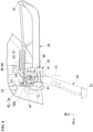
Fig. 1 is a left side view of a motorcycle according to an embodiment of the present invention. -
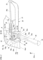
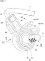
Fig. 2 is a left side view around a side stand of the motorcycle. -
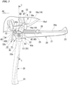
Fig. 3 is a diagram of surroundings of the side stand from an outer side in a rotation shaft direction. -
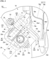
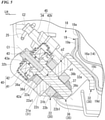
Fig. 4 is a diagram including a partial cross-section of the surroundings of the side stand viewed from a rear side in a longitudinal direction of the side stand. -
Fig. 5 is a cross-sectional view along line V-V inFig. 3 . -
Fig. 6 is a side view corresponding toFig. 2 showing an arrangement of a rotational positioning portion and a connector portion. -
Fig. 7 is a perspective view of the stand switch from an inner side in a vehicle width direction. - Hereinafter, embodiments of the present invention will be described with reference to the drawings. In addition, directions such as forward, rearward, leftward, and rightward in the following description are assumed to be the same as directions in a vehicle described below unless otherwise specified. Further, in appropriate places in figures used in the following description, an arrow FR indicating a forward direction in the vehicle, an arrow LH indicating a leftward direction in the vehicle, and an arrow UP indicating an upward direction in the vehicle are shown.
-
Fig. 1 shows a unit swing type motorcycle (a scooter type vehicle) 1 as an example of a saddle-riding type vehicle of the present embodiment. The motorcycle 1 includes a front wheel 3 serving as a steering wheel and arear wheel 4 serving as a driving wheel. The front wheel 3 is supported by a pair of left and rightfront forks 6 and can be steered by ahandlebar 2. Therear wheel 4 is supported by a swing unit (a power unit) U and can be driven by an engine E. - The swing unit U supports the
rear wheel 4 serving as the driving wheel to be vertically swingable. The swing unit U integrally includes the engine (internal combustion engine) E serving as a drive source and, for example, a V-belt type continuously variable transmission M. Therear wheel 4 is supported on an output shaft of the continuously variable transmission M at a rear portion thereof. The rear portion of the continuously variable transmission M is supported by avehicle body frame 11 via arear cushion 7. - Steering system components including the
handlebar 2, the left andright front forks 6 and the front wheel 3 are steerably supported by ahead pipe 12 at a front end portion of thevehicle body frame 11. The swing unit U and therear wheel 4 are supported by a pivot portion (not shown) at a lower portion of thevehicle body frame 11 to be vertically swingable via a suspension link or the like. - A front portion of the vehicle body is covered with a front cover 8, and a rear portion of the vehicle body is covered with a
rear cover 9. Abottom floor portion 10 is provided between the front cover 8 and therear cover 9. Astep floor 10a on which a driver rests his or her feet is provided on an upper surface of thebottom floor portion 10. Aseat 5 on which occupants including the driver are seated is supported on therear cover 9.Reference numeral 10b in the figure indicates a pair of left and right floor side covers that wrap around and below left and right side edges of thestep floor 10a. - The
vehicle body frame 11 includes thehead pipe 12 located at the front end portion, adown frame 13 extending downward from thehead pipe 12, a pair of left and rightlower frames 14 that bend rearward from a lower end portion of thedown frame 13, and a pair of left and right rear frames 15 extending to appropriately bend upward and rearward from rear end portion of the lower frames 14. The pivot portion that supports a front end portion of the swing unit U is provided in the vicinity of the rear end portions of the left and right lower frames 14. - As shown in
Fig. 1 , a foldabletype side stand 20 is attached to the left lower frame (vehicle body frame member) 14 of thevehicle body frame 11. The side stand 20 supports the vehicle body of the motorcycle 1 in an upright and leftwardly inclined state. - As shown in
Figs. 2 to 5 , the side stand 20 is rotatably supported by astand bracket 30 fixed to the leftlower frame 14. The side stand 20 is rotatable between a retracted position at which a tip side (grounding side) thereof is flipped up behind a rotation shaft 35 (which may be indicated by an axis C1 in the figure), and a usage position (standing position) in which the tip side is extended below therotation shaft 35. In the figure, the side stand 20 at the usage position is shown by a chain line. - The side stand 20 integrally includes, for example, a
stand bar 21 made of a straight steel pipe, apivot portion 22 that is provided on one end side (a base end side orrotation shaft 35 side) of thestand bar 21 and is rotatably connected to the vehicle body side, and a groundingportion 23 that is provided on the other end side (the tip side or grounding side) of thestand bar 21 and forms a grounding surface for supporting the vehicle body. - The
pivot portion 22 has a bifurcated shape that sandwiches a flat plate-shapedstand connection portion 31a of thestand bracket 30 in a plate thickness direction. Thepivot portion 22 includes a pair of twoplate portions plate portions stand connection portion 31a. Agroove portion 22c into which thestand connection portion 31a can be relatively rotatably inserted is formed between theplate portions Fig. 5 ) through which therotation shaft 35 is inserted are formed coaxially with each other in bothplate portions - The side stand 20 inserts the
stand connection portion 31a of thestand bracket 30 into thegroove portion 22c of thepivot portion 22. In this state, therotation shaft 35 penetrating thepivot portion 22 and thestand connection portion 31a is attached. As a result, the side stand 20 is rotatably connected to and supported by thestand bracket 30 via therotation shaft 35. - The
rotation shaft 35 is inclined upward such that a portion thereof on an outer side in the vehicle width direction is located on an upper side. As a result, when the side stand 20 is in the standing position, the side stand 20 is protruded outward in the vehicle width direction. Further, when the side stand 20 is in the retracted position, the side stand 20 is inhibited from protruding outward in the vehicle width direction. The side stand 20 in the standing position protruding outward in the vehicle width direction provides the following effects. That is, the groundingportion 23 is disposed on an outer side in the vehicle width direction to easily support the vehicle body of the motorcycle 1. By inhibiting the side stand 20 in the retracted position from protruding outward in the vehicle width direction, the following effects can be obtained. That is, the side stand 20 is less likely to be grounded when the vehicle body is banked. Therotation shaft 35 is also inclined in a longitudinal direction such that a portion thereof on the outer side in the vehicle width direction is located further forward. The line C1 in the figure indicates a central axis of therotation shaft 35. - The side stand 20 and its peripheral components may be unintentionally grounded. This grounding occurs in a case in which the vehicle body is largely banked during cornering or in a case in which it passes over unevenness on a road surface. In order to inhibit the side stand 20 from being affected by a bank angle or the minimum ground clearance of the vehicle body, an attachment position of the side stand 20 is preferably located as high as possible.
- A locking
hook 26 for locking one end portion of a stand spring (tensile coil spring) 25 is provided on the tip side of theside stand 20. The lockinghook 26 protrudes outward in the vehicle width direction from an intermediate portion of thestand bar 21 in a longitudinal direction thereof, and then bends toward the tip side of thestand bar 21. The lockinghook 26 bends toward the tip side of thestand bar 21 and then extends linearly to the groundingportion 23, and a tip portion thereof is welded to the groundingportion 23. An extension portion of the lockinghook 26 to the groundingportion 23 protrudes outward in the vehicle width direction on the tip side of thestand bar 21 to be afootrest portion 26a. Thefootrest portion 26a enables a rotation operation of the side stand 20 performed by a user's foot. - As shown in
Fig. 4 , at least the leftlower frame 14 of thevehicle body frame 11 is a press frame. The press frame is formed by integrally combining a plurality of press frame bodies. The leftlower frame 14 includes anouter frame body 16a on an outer side in the vehicle width direction and aninner frame body 16b on an inner side in the vehicle width direction. Both of theframe bodies frame bodies frame bodies lower frame 14 having a closed cross-sectional structure. - The left
lower frame 14 is provided with astand attachment portion 18 for attaching the site stand. Thestand attachment portion 18 includes a reinforcingbracket 19 welded and fixed to the leftlower frame 14, and thestand bracket 30 welded and fixed to the reinforcingbracket 19. In the present embodiment, the reinforcingbracket 19 and thestand bracket 30 are included in the configuration of thevehicle body frame 11. - The reinforcing
bracket 19 is formed to be bent in a substantially V shape when viewed in the longitudinal direction to straddle the leftlower frame 14 from below. The reinforcingbracket 19 includes anouter plate portion 19a, aninner plate portion 19b, and aninclined plate portion 19c. Theouter plate portion 19a is disposed along an outer surface of the leftlower frame 14 in the vehicle width direction and is joined to the outer surface. Theinner plate portion 19b is disposed along an inner side surface of the leftlower frame 14 in the vehicle width direction and is joined to the inner side surface. Theinclined plate portion 19c is inclined and extends below theouter plate portion 19a toward alower end portion 19d of the bracket to be located inward in the vehicle width direction toward a lower side thereof. - The
lower end portion 19d of the bracket has a U shape when viewed in the longitudinal direction. A lower end portion of theinner plate portion 19b is connected to an upper end portion of thelower end portion 19d of the bracket on an inner side thereof in the vehicle width direction. A lower end portion of theinclined plate portion 19c is connected to an upper end portion of thelower end portion 19d of the bracket on an outer side thereof in the vehicle width direction. - Also referring to
Figs. 2 and3 , a portion of the leftlower frame 14 to which the reinforcingbracket 19 is joined is a portion of theouter frame body 16a to which theouter plate portion 19a is joined. At this portion, a joggle (hereinafter, referred to as a recessedportion 18a) that changes the outer surface inward in the vehicle width direction is formed. The recessedportion 18a is located at a position overlapping aconnector portion 46, which will be described later, in a side view of the vehicle. The recessedportion 18a is also an avoidance portion that avoids the inner side of theconnector portion 46 in the vehicle width direction. - Referring to
Figs. 4 and5 , thestand bracket 30 includes abracket base 32 joined to the reinforcingbracket 19, and a connectingplate 31 that is joined to and held by thebracket base 32 to form thestand connection portion 31a. - The
bracket base 32 includes ajoint plate portion 32a and a frontend plate portion 32b. Thejoint plate portion 32a bends along the outer surface in the vehicle width direction at each of theinclined plate portion 19c and thelower end portion 19d of the bracket of the reinforcingbracket 19. The frontend plate portion 32b extends to bend downward in a direction orthogonal to theinclined plate portion 19c outward from a front end portion of thejoint plate portion 32a outward in the vehicle width direction. The frontend plate portion 32b extends outward in the vehicle width direction from astand switch 40, which will be described later, and inhibits the influence of disturbance from an outer side in the vehicle width direction on surroundings of thestand switch 40. - The connecting
plate 31 is disposed to be orthogonal to theinclined plate portion 19c. The connectingplate 31 is inclined to position both surfaces thereof in the plate thickness direction on a lower side toward the outer side in the vehicle width direction. The connectingplate 31 forms thestand connection portion 31a into which thepivot portion 22 of the side stand 20 is fitted. The connectingplate 31 is formed of a steel plate thicker than thebracket base 32. Thebracket base 32 is made of a steel plate thicker than the reinforcingbracket 19. The reinforcingbracket 19 is made of a steel plate thicker than theouter frame body 16a and theinner frame body 16b. - Also, the
stand attachment portion 18 is not limited to the above configuration. For example, thevehicle body frame 11 may be made of a steel pipe, thestand bracket 30 may be an integrally formed product, or thestand bracket 30 may be configured to be detachably fixed to thevehicle body frame 11 by bolt-fastening or the like. - The
stand connection portion 31a forms ashaft insertion hole 31b (seeFig. 5 ) penetrating in the plate thickness direction at a substantially central portion thereof in a plan view. The shaft insertion hole 3 1b has the following arrangement in a state in which the connectingplate 31 is inserted into thegroove portion 22c of thepivot portion 22. Theshaft insertion hole 31b is coaxially disposed with the shaft insertion holes 22a1 and 22b1 provided in the pair ofplate portions pivot portion 22. - As shown in
Fig. 5 , therotation shaft 35 is configured as a so-called steppedbolt 36. The steppedbolt 36 is removably inserted from an outer side in the vehicle width direction into the insertion holes 22a1, 22b1, and 31b of thepivot portion 22 and thestand connection portion 31a. The steppedbolt 36 includes ahead portion 36a located on an outer side in the vehicle width direction, ashaft portion 36b connected to an inner side of thehead portion 36a in the vehicle width direction, and ascrew shaft 36c protruding inward in the vehicle width direction of thepivot portion 22. - The shaft insertion hole 22a1 of the
plate portion 22a on an outer side of thepivot portion 22 in the vehicle width direction and theshaft insertion hole 31b of thestand connection portion 31a have the same diameter. Theshaft portion 36b of the steppedbolt 36 can be inserted into each of the shaft insertion holes 22a1 and 31b. The shaft insertion hole 22b1 of theplate portion 22b on the inner side of thepivot portion 22 in the vehicle width direction is set to the following diameter. The shaft insertion hole 22b1 has a smaller diameter than each of the shaft insertion holes 22a1 and 3 1b of theplate portion 22a and thestand connection portion 31a on the outer side of thepivot portion 22 in the vehicle width direction. Thescrew shaft 36c of the steppedbolt 36 can be inserted into the shaft insertion hole 22b1, but cannot be inserted into theshaft portion 36b. A circumferential edge of the shaft insertion hole 22b1 on the outer side in the vehicle width direction (on thestand connection portion 31a side) is a seating surface that abuts a tip surface of theshaft portion 36b. Theshaft portion 36b has a larger diameter than thescrew shaft 36c. - When the side stand 20 is assembled, the
shaft portion 36b of the steppedbolt 36 is inserted into the shaft insertion holes 22a1 and 31b of theplate portion 22a of thepivot portion 22 on the outer side in the vehicle width direction and thestand connection portion 31a. In this case, theshaft portion 36b causes the tip surface to abut a peripheral edge portion of the shaft insertion hole 22b1 of theplate portion 22b on the inner side in the vehicle width direction. In this state, anut 37 is screwed and tightened to thescrew shaft 36c protruding inward from thepivot portion 22 in the vehicle width direction. Thus, the steppedbolt 36 is fixed to theplate portion 22b on the inner side in the vehicle width direction. As a result, thepivot portion 22 is rotatably supported on and connected to thestand connection portion 31a via the steppedbolt 36. - Referring to
Figs. 2 to 4 , a stepped frontlower stopper portion 33a that defines the standing position of the side stand 20 is formed at a front lower portion of the connectingplate 31. The frontlower stopper portion 33a abuts one end side of thepivot portion 22 in a rotation direction thereof from behind to define the standing position of theside stand 20. A stepped rearupper stopper portion 33b that defines the retracted position of the side stand 20 is formed on a rear upper portion of the connectingplate 31. The rearupper stopper portion 33b abuts the other end side of thepivot portion 22 in the rotation direction from below to define the retracted position of theside stand 20. - A locking
pin 34 for locking the other end portion of the stand spring (tensile coil spring) 25 is provided to protrude from a front upper portion of the connectingplate 31. The lockingpin 34 is provided, for example, in parallel with therotation shaft 35. Thestand spring 25 is provided to stretch between the lockinghook 26 of the side stand 20 and the lockingpin 34 of thestand connection portion 31a. Thestand spring 25 holds a rotational position of the side stand 20 in the standing position or the retracted position due to its own tension. A line C2 in the figure indicates a central axis of the lockingpin 34. - As shown in
Figs. 2 to 5 , thestand switch 40 for detecting the rotational position of the side stand 20 is provided on the outer side of thepivot portion 22 in the vehicle width direction. - The
stand switch 40 is a rotary switch provided coaxially with therotation shaft 35. Thestand switch 40 detects whether the side stand 20 is in the usage position or the retracted position and outputs a corresponding electric signal. This electric signal is sent to an engine control unit (not shown) and used for various controls. This control is, for example, control for making it impossible to start the engine E when the side stand 20 is in the usage position while the engine E is stopped. Further, for example, the control is control for stopping the engine E when the side stand 20 rotates from the retracted position to the usage position while the engine E is in operation. - Referring to
Fig. 5 , thestand switch 40 includes arotor 41 and acase 42. Therotor 41 is provided to be rotatable integrally with theside stand 20. Thecase 42 accommodates therotor 41 and is provided to be rotatable relative to theside stand 20. - The
rotor 41 is disposed on an outer side of thehead portion 36a of the steppedbolt 36 in the vehicle width direction. Aswitch attachment bolt 43 coaxial with the steppedbolt 36 can be inserted into therotor 41. Theswitch attachment bolt 43 penetrates therotor 41 and is screwed and tightened to ascrew hole 36d provided to protrude on thehead portion 36a side of the steppedbolt 36. As a result, therotor 41 can rotate integrally with the steppedbolt 36 and thus theside stand 20. - Also referring to
Fig. 3 , thecase 42 has a circular shape when viewed in the axial direction of therotation shaft 35. Thecase 42 has a cup shape that covers therotor 41 from an outer side in the vehicle width direction. Thecase 42 is disposed close to theplate portion 22a on the outer side of thepivot portion 22 in the vehicle width direction via athrust washer 42a or the like. In this state, detachment of thecase 42 outward in the vehicle width direction is restricted by a large-diameter washer 43a used for a seating surface of theswitch attachment bolt 43. As a result, thecase 42 is attached to the outer side of thepivot portion 22 in the vehicle width direction. - The locking
pin 34 for locking thestand spring 25 is located in front of and above thecase 42. A lockingclaw portion 42b is provided to protrude from a front upper portion of thecase 42 toward an outer peripheral side (outer side in a radial direction) of thecase 42. The lockingclaw portion 42b forms aU-shaped locking groove 42c that opens to the outer peripheral side of thecase 42. The lockingpin 34 can be engaged into the lockinggroove 42c. The lockingclaw portion 42b and the lockingpin 34 constitute arotational positioning portion 45 that performs positioning of thecase 42 in the rotation direction of theside stand 20. - Referring to
Figs. 4 and5 , reference numerals p1 and p2 in the figure indicate the following intersection points. These intersection points are intersection points between the central axes C1 and C2 of therotation shaft 35 and the lockingpin 34 and the outer surface of the connecting plate 31 (a plane orthogonal to the rotation shaft 35) on the outer side in the vehicle width direction. For example, these intersection points are defined as axial centers p1 and p2 of therotation shaft 35 and the lockingpin 34. - Referring to
Fig. 6 , a straight line connecting the axial center p1 of therotation shaft 35 to the axial center p2 of the lockingpin 34 in the side view of the vehicle is defined as a first straight line T1. The axial center p2 corresponds to a positioning center of therotational positioning portion 45. - Referring to
Figs. 2 and3 , theconnector portion 46 is disposed on a rear upper side of thecase 42. Theconnector portion 46 makes it possible to connect electric wiring (harness) H extending from the vehicle body side to thestand switch 40. Theconnector portion 46 includes aterminal portion 47 and acoupler 48. Theterminal portion 47 is provided to protrude from a rear upper portion of thecase 42 toward the outer peripheral side of thecase 42. Thecoupler 48 is externally fitted by inserting theterminal portion 47 thereinto from the outer peripheral side of thecase 42. Aline C3 inFig. 3 indicates a central axis in an insertion and removal direction (wiring attachment and detachment direction) of thecoupler 48 in theconnector portion 46. The insertion and removal direction of thecoupler 48 is a direction parallel to a plane orthogonal to therotation shaft 35. - Referring to
Fig. 6 , a straight line along the central axis C3 in the side view of the vehicle is defined as a second straight line T2. - Referring to
Figs. 2 and6 , in the side view of the vehicle, therotational positioning portion 45 and theconnector portion 46 are disposed with respect to therotation shaft 35 of the side stand 20 as follows. That is, therotational positioning portion 45 and theconnector portion 46 are disposed to be distributed on front and rear side in the longitudinal direction of the vehicle. In the side view of the vehicle, therotational positioning portion 45 is disposed in front of therotation shaft 35. Further, theconnector portion 46 is disposed behind therotation shaft 35. The line T3 inFig. 6 indicates a vertical line passing through the axial center p1 of therotation shaft 35 in the side view of the vehicle. - In the side view of the vehicle, a straight line connecting the axial center p1 of the
rotation shaft 35 to the positioning center p2 of therotational positioning portion 45 is defined as the first straight line T1. The first straight line T1 extends diagonally from therotation shaft 35 side to therotational positioning portion 45 side toward a front upper side. In the side view of the vehicle, the straight line in the wiring attachment and detachment direction (central axis C3) of theconnector portion 46 is defined as the second straight line T2. The second straight line T2 extends diagonally from therotation shaft 35 side to theconnector portion 46 side toward a rear upper side. In the side view of the vehicle, the first straight line T1 and the second straight line T2 are disposed in a V shape at a relative angle to intersect each other. - In the present embodiment, the
rotational positioning portion 45 is disposed on the front side of the vehicle and theconnector portion 46 is disposed on the rear side of the vehicle with reference to therotation shaft 35 of thestand switch 40. That is, therotational positioning portion 45 and theconnector portion 46 of thestand switch 40 are dispersedly disposed in the longitudinal direction of the vehicle. This makes it possible to reduce a distance between thestand switch 40 and thevehicle body frame 11. Accordingly, surroundings of the side stand 20 can be made compact. Further, by bringing the side stand 20 closer to the vehicle body (displacing it upward), the following effects can be obtained. That is, when the vehicle body is banked, it becomes difficult for the side stand 20 to be grounded, and it becomes easy to secure the minimum ground clearance. - Further, in the present embodiment, in the side view of the vehicle, a rearward inclination angle θ2 of the second straight line T2 with respect to the vertical line T3 passing through the axial center p1 of the
rotation shaft 35 is set as follows. That is, the inclination angle θ2 is set to be smaller than a forward inclination angle θ1 of the first straight line T1 with respect to the vertical line T3 (that is, to be more upright). This makes it easier to extend the wiring H extending from theconnector portion 46 upward (toward the vehicle body side). Accordingly, arrangement of the wiring H can be improved and reduction in length of the wiring H can be achieved. - Also, referring to
Fig. 4 , in the present embodiment, in the axial direction of therotation shaft 35, aninner side surface 46d of theconnector portion 46 on the inner side in the vehicle width direction is located outward in the vehicle width direction from theouter side surface 22d of thepivot portion 22 on the outer side in the vehicle width direction. That is, theconnector portion 46 is offset outward in the vehicle width direction with respect to thecase 42 in the axial direction of therotation shaft 35. In the axial direction of therotation shaft 35, the central axis C3 of theconnector portion 46 is offset outward in the vehicle width direction with respect to a height center of the case 42 (indicated by a line T4 in the figure). In the axial direction of therotation shaft 35, theinner side surface 46d of theconnector portion 46 on the inner side in the vehicle width direction is separated from theouter side surface 22d of thepivot portion 22 on the outer side in the vehicle width direction by an interval k outward in the vehicle width direction. - In the present embodiment, in the axial direction (rotation shaft direction) of the
rotation shaft 35 of theside stand 20, theinner side surface 46d of theconnector portion 46 on the inner side in the vehicle width direction is disposed outward in the vehicle width direction from theouter side surface 22d of thepivot portion 22 of the side stand 20 on the outer side in the vehicle width direction. As a result, when viewed from the rotation shaft direction, interference between therotating pivot portion 22 and theconnector portion 46 is avoided even if theconnector portion 46 is in a position overlapping a rotation range of thepivot portion 22. - As shown in
Fig. 7 , theconnector portion 46 of thestand switch 40 includes alock portion 46a. Thelock portion 46a restricts removal of thecoupler 48 from theterminal portion 47 in a connected state in which theterminal portion 47 and thecoupler 48 are fitted to each other. Theconnector portion 46 includes aunlock operation portion 46b that enables thecoupler 48 to perform an unlock operation of the removal restriction of thelock portion 46a. Theunlock operation portion 46b is disposed on the inner side of theconnector portion 46 in the vehicle width direction. - As described above, the side stand structure in the above embodiment includes the side stand 20 rotatably supported by the vehicle body (vehicle body frame 11), the
stand switch 40 configured to detect the rotational position of theside stand 20, therotational positioning portion 45 configured to position thestand switch 40 in the rotation direction of theside stand 20, and theconnector portion 46 configured to connect the wiring H to thestand switch 40. Therotational positioning portion 45 and theconnector portion 46 are disposed to be distributed in front of and behind therotation shaft 35 of the side stand 20 in the longitudinal direction of the vehicle. - According to this configuration, the
rotational positioning portion 45 and theconnector portion 46 of the side stand 20 are disposed to be distributed in front of and behind therotation shaft 35 of the side stand 20 in the longitudinal direction of the vehicle, and thus the following effects are obtained. That is, as compared with a case in which both therotational positioning portion 45 and theconnector portion 46 protruding toward the outer peripheral side of thestand switch 40 are one-sidedly disposed on one side of therotation shaft 35 in the longitudinal direction of the vehicle, thestand switch 40 can be disposed to be closer to the vehicle body in the vehicle width direction and the vertical direction. For this reason, surroundings of the side stand 20 can be made compact, and unintended grounding of the side stand 20 can be easily avoided by moving the side stand 20 upward. - Further, in the side stand structure, the
rotational positioning portion 45 is disposed in front of therotation shaft 35 of the side stand 20 and theconnector portion 46 is disposed behind therotation shaft 35 of theside stand 20. - According to this configuration, since the
rotational positioning portion 45 is disposed in front of therotation shaft 35, and theconnector portion 46 is disposed behind therotation shaft 35, the lockingpin 34 or the like held by therotational positioning portion 45 on the vehicle body side is disposed in front of therotation shaft 35. Normally, the side stand 20 rotates between the usage position extending downward from therotation shaft 35 and the retracted position extending rearward. For this reason, by disposing therotational positioning portion 45 in front of therotation shaft 35, the lockingpin 34 or the like is retracted from the rotation range of theside stand 20. As a result, therotational positioning portion 45 and theconnector portion 46 can be disposed to be distributed in the longitudinal direction of the vehicle without obstructing the rotation range of theside stand 20. Further, since theconnector portion 46 that is an electrical component is one-sidedly disposed rearward, it is possible to improve waterproofness and dust-proofness of theconnector portion 46. - Also, in the side stand structure, the side stand 20 includes the
pivot portion 22 rotatably connected to the vehicle body, and, in an axial direction of therotation shaft 35, theinner side surface 46d of theconnector portion 46 on the inner side in the vehicle width direction is disposed to be separated from theouter side surface 22d of thepivot portion 22 outward in the vehicle width direction. - According to this configuration, since the
connector portion 46 is disposed to be separated from thepivot portion 22 outward in the vehicle width direction, it is possible to reliably prevent the side stand 20 and theconnector portion 46 from interfering with each other when the side stand 20 rotates. - Also, in the side stand structure, in the side view of the vehicle, the
rotational positioning portion 45 is disposed in front of and above therotation shaft 35, theconnector portion 46 is disposed above and behind therotation shaft 35, the wiring H is attachable to and detachable from theconnector portion 46 along the axis C3 that rises rearward in the side view of the vehicle, and when the straight line connecting the axial center p1 of therotation shaft 35 to the axial center p2 of the lockingpin 34 held by therotational positioning portion 45 on the vehicle body side in the side view of the vehicle is defined as the first straight line T1 and the straight line along the axis C3 of theconnector portion 46 in the side view of the vehicle is defined as the second straight line T2, the rearward inclination angle θ2 of the second straight line T2 with respect to the vertical line T3 passing through the axial center p1 of therotation shaft 35 in the side view of the vehicle is set to be smaller than the forward inclination angle θ1 of the first straight line T1 with respect to the vertical line T3. - According to this configuration, since the rearward inclination angle θ2 of the second straight line T2 on the
connector portion 46 side is set to be smaller than the forward inclination angle θ1 of the first straight line T1 on therotational positioning portion 45 side (that is, more upright), the wiring H extending from theconnector portion 46 can be easily extended upward (on the vehicle body side), so that arrangement of the wiring H can be improved and reduction in length of the wiring H can be achieved. - Also, in the side stand structure, the
stand bracket 30 configured to rotatably support the side stand 20 and thelower frame 14 configured to fix thestand bracket 30 are provided on the vehicle body side, and thelower frame 14 includes the recessedportion 18a that overlaps at least a part of theconnector portion 46 in the side view of the vehicle. - According to this configuration, since the
lower frame 14 includes the recessedportion 18a that overlaps theconnector portion 46, it is possible to bring theside stand 20, including theconnector portion 46, closer to thelower frame 14. For this reason, surroundings of the side stand 20 can be made compact, and grounding of the side stand 20 can be easily avoided by moving the side stand 20 upward. - Also, in the side stand structure, the
connector portion 46 includes thelock portion 46a configured to lock theconnector portion 46 in a coupled state, and theunlock operation portion 46b configured to performs the unlock operation of thelock portion 46a, and theunlock operation portion 46b is disposed on the inner side of theconnector portion 46 in the vehicle width direction. - According to this configuration, since the
unlock operation portion 46b of theconnector portion 46 is disposed on the inner side of theconnector portion 46 in the vehicle width direction, it is possible to inhibit unauthorized access to theconnector portion 46 and to achieve improvement in appearance by adopting the arrangement in which theunlock operation portion 46b is difficult to be seen from the outside in the vehicle width direction. - Also, the present invention is not limited to the above embodiment. For example, the vehicle body to which the side stand is attached is not limited to the vehicle body frame and may be a structure attached to the vehicle body frame or a power unit such as an engine. A configuration in which the rotational positioning portion is disposed behind the rotation shaft, and the connector portion is disposed in front of the rotation shaft may be adopted. A configuration in which in the rotational positioning portion, the positioning pin is disposed on the stand switch side, and a pin engaging portion is disposed on the vehicle body side may be adopted.
- Vehicles to which the present invention is applied include all vehicles provided with a side stand. That is, not only motorcycles (including motorized bicycles and scooter type vehicles), but also three-wheeled vehicles (including front two-wheeled and rear one-wheeled vehicles in addition to front one-wheeled and rear two-wheeled vehicles), four-wheeled vehicles, and vehicles including an electric motor as a prime mover are also included.
- The configuration in the above embodiment is an example of the present invention, and various changes can be made without departing from the gist of the present invention, such as replacing the constituent elements of the embodiment with well-known constituent elements.
-
- 1
- Motorcycle (saddle-riding type vehicle)
- 11
- Vehicle body frame (vehicle body)
- 14
- Lower frame (vehicle body frame member)
- 18
- Stand attachment portion
- 18a
- Recessed portion
- 20
- Side stand
- 22
- Pivot portion
- 22d
- Outer side surface
- 30
- Stand bracket
- 34
- Locking pin (positioning pin)
- P2
- Axial center, positioning center
- 35
- Rotation shaft
- PI
- Axial center
- 40
- Stand switch
- 45
- Rotational positioning portion
- 46
- Connector portion
- 46a
- Lock portion
- 46b
- Unlock operation portion
- 46d
- Inner side surface
- H
- Wiring
- C3
- Axis
- T1
- First straight line
- θ1
- Inclination angle
- T2
- Second straight line
- θ2
- Inclination angle
- T3
- Vertical line
Claims (6)
- A side stand structure comprising:a side stand (20) rotatably supported by a vehicle body (11); anda stand switch (40) configured to detect a rotational position of the side stand (20),wherein the side stand structure includes a rotational positioning portion (45) configured to position the stand switch (40) in a rotation direction of the side stand (20), and a connector portion (46) configured to connect wiring (H) to the stand switch (40),a first straight line (T1) connecting an axial center (p1) of a rotation shaft (35) of the side stand (20) to a positioning center (p2) of the rotational positioning portion (45) in a side view of a vehicle extends from the rotation shaft (35) side to the rotational positioning portion (45) side in one of forward and rearward directions of a longitudinal direction of the vehicle, anda second straight line (T2) in a wiring attachment and detachment direction of the connector portion (46) in the side view of the vehicle extends from the rotation shaft (35) side to the connector portion (46) side in the other of the forward and rearward directions of the longitudinal direction of the vehicle.
- The side stand structure according to claim 1,wherein the first straight line (T1) in the side view of the vehicle extends from the rotation shaft (35) side to the rotational positioning portion (45) side in the forward direction of the longitudinal direction of the vehicle, andthe second straight line (T2) in the side view of the vehicle extends from the rotation shaft (35) side to the connector portion (46) side in the rearward direction of the longitudinal direction of the vehicle.
- The side stand structure according to claim 2,wherein the side stand (20) includes a pivot portion (22) rotatably connected to the vehicle body (11), andin an axial direction of the rotation shaft (35), an inner side surface (46d) of the connector portion (46) on an inner side in a vehicle width direction is disposed to be separated outward in the vehicle width direction from an outer side surface (22d) of the pivot portion (22) on an outer side in the vehicle width direction.
- The side stand structure according to any one of claims 1 to 3,wherein, in the side view of the vehicle, the rotational positioning portion (45) is disposed in front of and above the rotation shaft (35), and the connector portion (46) is disposed above and behind the rotation shaft (35),the wiring (H) is attachable to and detachable from the connector portion (46) along an axis (C3) that rises rearward, andwhen a straight line connecting the axial center (p1) of the rotation shaft (35) to an axial center (p2) of a positioning pin (34) held by the rotational positioning portion (45) on the vehicle body (11) side in the side view of the vehicle is defined as the first straight line (T1) and a straight line along the axis (C3) of the connector portion (46) in the side view of the vehicle is defined as the second straight line (T2),a rearward inclination angle (θ2) of the second straight line (T2) with respect to a vertical line (T3) passing through the axial center (p1) of the rotation shaft (35) in the side view of the vehicle is set to be smaller than a forward inclination angle (θ1) of the first straight line (T1) with respect to the vertical line (T3).
- The side stand structure according to any one of claims 1 to 4,wherein a stand bracket (30) configured to rotatably support the side stand (20) and a vehicle body frame member (14) configured to fix the stand bracket (30) are provided on the vehicle body (11) side, andthe vehicle body frame member (14) includes a recessed portion (18a) that overlaps at least a part of the connector portion (46) in the side view of the vehicle.
- The side stand structure according to any one of claims 1 to 4,wherein the connector portion (46) includes a lock portion (46a) configured to lock the connector portion (46) in a coupled state, and an unlock operation portion (46b) configured to perform an unlock operation of the lock portion (46a), andthe unlock operation portion (46b) is disposed on an inner side of the connector portion (46) in the vehicle width direction.
Applications Claiming Priority (2)
| Application Number | Priority Date | Filing Date | Title |
|---|---|---|---|
| JP2019086704 | 2019-04-26 | ||
| PCT/JP2020/012448 WO2020217803A1 (en) | 2019-04-26 | 2020-03-19 | Side stand structure |
Publications (3)
| Publication Number | Publication Date |
|---|---|
| EP3960596A1 true EP3960596A1 (en) | 2022-03-02 |
| EP3960596A4 EP3960596A4 (en) | 2022-06-22 |
| EP3960596B1 EP3960596B1 (en) | 2024-05-15 |
Family
ID=72941995
Family Applications (1)
| Application Number | Title | Priority Date | Filing Date |
|---|---|---|---|
| EP20794804.3A Active EP3960596B1 (en) | 2019-04-26 | 2020-03-19 | Side stand structure |
Country Status (6)
| Country | Link |
|---|---|
| EP (1) | EP3960596B1 (en) |
| JP (1) | JP7154402B2 (en) |
| CN (1) | CN113727908B (en) |
| BR (1) | BR112021020152A2 (en) |
| MY (1) | MY196787A (en) |
| WO (1) | WO2020217803A1 (en) |
Family Cites Families (17)
| Publication number | Priority date | Publication date | Assignee | Title |
|---|---|---|---|---|
| US4883284A (en) * | 1987-12-25 | 1989-11-28 | Honda Giken Kogyo Kabushiki Kaisha | Position detecting device for a motorcycle side stand |
| JPH0631038B2 (en) * | 1987-12-25 | 1994-04-27 | 本田技研工業株式会社 | Motorcycle side stand |
| JPH0754060Y2 (en) * | 1988-08-12 | 1995-12-13 | 株式会社本田ロック | Side stand rotation position detection switch |
| JPH0233191U (en) * | 1988-08-26 | 1990-03-01 | ||
| IT1283499B1 (en) * | 1996-07-24 | 1998-04-21 | Ducati Motorcycles S P A | MOTORCYCLE STARTING CONSENT DEVICE |
| JP3884223B2 (en) * | 2000-09-11 | 2007-02-21 | 本田技研工業株式会社 | Side stand support device for motorcycles |
| JP4771420B2 (en) * | 2006-01-12 | 2011-09-14 | 本田技研工業株式会社 | Side stand switch |
| JP5314475B2 (en) * | 2009-03-26 | 2013-10-16 | パナソニック株式会社 | Rotary sensor |
| CN201856836U (en) * | 2010-08-31 | 2011-06-08 | 光阳工业股份有限公司 | Side bracket module of electric-operated motor cycle |
| JP5984086B2 (en) * | 2012-05-25 | 2016-09-06 | パナソニックIpマネジメント株式会社 | Rotary switch |
| WO2014109332A1 (en) * | 2013-01-10 | 2014-07-17 | アルプス電気株式会社 | Side stand position detection device |
| JP2014241223A (en) * | 2013-06-11 | 2014-12-25 | パナソニックIpマネジメント株式会社 | Rotary switch device |
| IN2014MU02141A (en) * | 2014-07-02 | 2015-04-24 | Star Engineers I Pvt Ltd | |
| CN110087980B (en) * | 2016-12-28 | 2020-12-25 | 本田技研工业株式会社 | Support switch |
| MY196923A (en) * | 2016-12-28 | 2023-05-11 | Alps Alpine Co Ltd | Stand position detecting device |
| JP6853151B2 (en) * | 2017-09-26 | 2021-03-31 | アルプスアルパイン株式会社 | Stand position detector |
| JP2019086704A (en) | 2017-11-09 | 2019-06-06 | コニカミノルタ株式会社 | Optical writing device and image forming apparatus |
-
2020
- 2020-03-19 CN CN202080030722.5A patent/CN113727908B/en active Active
- 2020-03-19 EP EP20794804.3A patent/EP3960596B1/en active Active
- 2020-03-19 MY MYPI2021006272A patent/MY196787A/en unknown
- 2020-03-19 WO PCT/JP2020/012448 patent/WO2020217803A1/en unknown
- 2020-03-19 JP JP2021515881A patent/JP7154402B2/en active Active
- 2020-03-19 BR BR112021020152A patent/BR112021020152A2/en unknown
Also Published As
| Publication number | Publication date |
|---|---|
| CN113727908B (en) | 2023-07-25 |
| CN113727908A (en) | 2021-11-30 |
| MY196787A (en) | 2023-05-03 |
| EP3960596B1 (en) | 2024-05-15 |
| JP7154402B2 (en) | 2022-10-17 |
| EP3960596A4 (en) | 2022-06-22 |
| BR112021020152A2 (en) | 2021-12-14 |
| JPWO2020217803A1 (en) | 2021-11-25 |
| WO2020217803A1 (en) | 2020-10-29 |
Similar Documents
| Publication | Publication Date | Title |
|---|---|---|
| JP5046994B2 (en) | Side stand mounting structure for motorcycles | |
| JP5178248B2 (en) | Rear structure of saddle-ride type vehicle | |
| JP2015033900A (en) | Fitting structure of front cowl stay in saddle-riding type vehicle | |
| EP3960596A1 (en) | Side stand structure | |
| EP1772363B1 (en) | Scooter type motorcycle | |
| JP5208559B2 (en) | Electrical component storage structure for saddle-ride type vehicles | |
| JP6295291B2 (en) | Screen device and vehicle | |
| JP6705049B2 (en) | Meter mounting structure for saddle type vehicles | |
| EP3281849B1 (en) | Sidestand structure in two-wheeled motor vehicle | |
| EP3088284B1 (en) | Straddled vehicle | |
| JP4503519B2 (en) | Vehicle fuel tank arrangement structure | |
| JP5775914B2 (en) | Cable routing structure for electrical components in saddle-ride type vehicles | |
| JP3900406B2 (en) | Body front structure in saddle riding type vehicle | |
| JP7369749B2 (en) | saddle type vehicle | |
| JP6606282B2 (en) | Stand support structure for saddle-ride type vehicles | |
| JP4156758B2 (en) | Auxiliary stand for motorcycles | |
| CN106741505B (en) | Straddle-type vehicle | |
| JP7210624B2 (en) | straddle-type vehicle | |
| US11772735B2 (en) | Main step structure for saddle riding vehicle | |
| JP6965224B2 (en) | Saddle-type vehicle | |
| EP3150471B1 (en) | Windshield for vehicle | |
| JP6290759B2 (en) | Center stand structure for saddle riding type vehicles | |
| JP2012245940A (en) | Saddle-type vehicle | |
| JP2022034859A (en) | Saddle-riding type vehicle | |
| WO2007083260A1 (en) | A frame for cycles |
Legal Events
| Date | Code | Title | Description |
|---|---|---|---|
| STAA | Information on the status of an ep patent application or granted ep patent |
Free format text: STATUS: THE INTERNATIONAL PUBLICATION HAS BEEN MADE |
|
| PUAI | Public reference made under article 153(3) epc to a published international application that has entered the european phase |
Free format text: ORIGINAL CODE: 0009012 |
|
| STAA | Information on the status of an ep patent application or granted ep patent |
Free format text: STATUS: REQUEST FOR EXAMINATION WAS MADE |
|
| 17P | Request for examination filed |
Effective date: 20211012 |
|
| AK | Designated contracting states |
Kind code of ref document: A1 Designated state(s): AL AT BE BG CH CY CZ DE DK EE ES FI FR GB GR HR HU IE IS IT LI LT LU LV MC MK MT NL NO PL PT RO RS SE SI SK SM TR |
|
| A4 | Supplementary search report drawn up and despatched |
Effective date: 20220519 |
|
| RIC1 | Information provided on ipc code assigned before grant |
Ipc: B62H 1/02 20060101AFI20220513BHEP |
|
| DAV | Request for validation of the european patent (deleted) | ||
| DAX | Request for extension of the european patent (deleted) | ||
| STAA | Information on the status of an ep patent application or granted ep patent |
Free format text: STATUS: EXAMINATION IS IN PROGRESS |
|
| 17Q | First examination report despatched |
Effective date: 20230223 |
|
| REG | Reference to a national code |
Ref country code: DE Ref legal event code: R079 Free format text: PREVIOUS MAIN CLASS: B62H0001020000 Ipc: B62J0045000000 Ref country code: DE Ref legal event code: R079 Ref document number: 602020031023 Country of ref document: DE Free format text: PREVIOUS MAIN CLASS: B62H0001020000 Ipc: B62J0045000000 |
|
| RIC1 | Information provided on ipc code assigned before grant |
Ipc: B62J 45/00 20200101AFI20231013BHEP |
|
| RIC1 | Information provided on ipc code assigned before grant |
Ipc: B62J 45/413 20200101ALI20231108BHEP Ipc: B62J 45/42 20200101ALI20231108BHEP Ipc: B62H 1/02 20060101ALI20231108BHEP Ipc: B62J 45/00 20200101AFI20231108BHEP |
|
| GRAP | Despatch of communication of intention to grant a patent |
Free format text: ORIGINAL CODE: EPIDOSNIGR1 |
|
| STAA | Information on the status of an ep patent application or granted ep patent |
Free format text: STATUS: GRANT OF PATENT IS INTENDED |
|
| INTG | Intention to grant announced |
Effective date: 20231215 |
|
| GRAS | Grant fee paid |
Free format text: ORIGINAL CODE: EPIDOSNIGR3 |
|
| GRAA | (expected) grant |
Free format text: ORIGINAL CODE: 0009210 |
|
| STAA | Information on the status of an ep patent application or granted ep patent |
Free format text: STATUS: THE PATENT HAS BEEN GRANTED |