EP3960591A1 - Schotteil - Google Patents
Schotteil Download PDFInfo
- Publication number
- EP3960591A1 EP3960591A1 EP20193282.9A EP20193282A EP3960591A1 EP 3960591 A1 EP3960591 A1 EP 3960591A1 EP 20193282 A EP20193282 A EP 20193282A EP 3960591 A1 EP3960591 A1 EP 3960591A1
- Authority
- EP
- European Patent Office
- Prior art keywords
- carrier
- expansion material
- effective sealing
- section
- partition part
- Prior art date
- Legal status (The legal status is an assumption and is not a legal conclusion. Google has not performed a legal analysis and makes no representation as to the accuracy of the status listed.)
- Granted
Links
Images

Classifications
-
- B—PERFORMING OPERATIONS; TRANSPORTING
- B60—VEHICLES IN GENERAL
- B60R—VEHICLES, VEHICLE FITTINGS, OR VEHICLE PARTS, NOT OTHERWISE PROVIDED FOR
- B60R13/00—Elements for body-finishing, identifying, or decorating; Arrangements or adaptations for advertising purposes
- B60R13/08—Insulating elements, e.g. for sound insulation
- B60R13/0815—Acoustic or thermal insulation of passenger compartments
- B60R13/0823—Insulating partitions, e.g. between front and rear seats
-
- B—PERFORMING OPERATIONS; TRANSPORTING
- B62—LAND VEHICLES FOR TRAVELLING OTHERWISE THAN ON RAILS
- B62D—MOTOR VEHICLES; TRAILERS
- B62D25/00—Superstructure or monocoque structure sub-units; Parts or details thereof not otherwise provided for
-
- B—PERFORMING OPERATIONS; TRANSPORTING
- B62—LAND VEHICLES FOR TRAVELLING OTHERWISE THAN ON RAILS
- B62D—MOTOR VEHICLES; TRAILERS
- B62D29/00—Superstructures, understructures, or sub-units thereof, characterised by the material thereof
- B62D29/001—Superstructures, understructures, or sub-units thereof, characterised by the material thereof characterised by combining metal and synthetic material
- B62D29/002—Superstructures, understructures, or sub-units thereof, characterised by the material thereof characterised by combining metal and synthetic material a foamable synthetic material or metal being added in situ
-
- B—PERFORMING OPERATIONS; TRANSPORTING
- B60—VEHICLES IN GENERAL
- B60Y—INDEXING SCHEME RELATING TO ASPECTS CROSS-CUTTING VEHICLE TECHNOLOGY
- B60Y2306/00—Other features of vehicle sub-units
- B60Y2306/09—Reducing noise
Definitions
- the invention relates to a bulkhead part for sealing and/or supporting a cavity, comprising a carrier and an expansion material arranged on the carrier, which can be converted from an initial state into an expanded state by activation.
- the bulkhead parts are used for acoustic and/or watertight sealing and partitioning and/or support of cavities in the body.
- the bulkhead parts include a carrier, which is equipped with an expansion material all around.
- the expansion material is characterized in that it can be converted from an initial state into an expanded state by activation when the bulkhead part is installed, in which it acts as a sealing and/or supporting material between the carrier and adjacent components of the body.
- the present invention has therefore set itself the task of providing a bulkhead part for sealing and/or supporting a cavity in body construction which is simple is to be produced, in the installed state offers a very good seal against noise and moisture and by means of which a retraction or bulging of a component adjacent to the bulkhead part, in particular an outer panel, can be prevented.
- the carrier comprises at least one compensating element, through which a variability of the effective sealing surface of the carrier is given, such that a change in the effective sealing surface of the carrier can be brought about by a force acting on the carrier, wherein a limiting element is provided, by means of which a movement associated with the change in the effective sealing area of at least one section of the carrier is limited.
- the bulkhead according to the invention is used to seal a cavity and is used for this purpose in a surface delimiting the cavity.
- the surface delimiting the cavity, which is to be sealed is also referred to below as the delimiting surface.
- both the carrier and the expansion material of the partition part contribute to the sealing of the boundary surface.
- the effective sealing surface of the carrier is understood to mean a projection surface of the carrier which, when the partition part is installed, lies in the plane of the boundary surface or parallel to it.
- the effective sealing surface of the partition part refers to the projection surface of the entire partition part, which covers the entire boundary surface and effectively seals it in the installed state.
- the invention also includes bulkhead parts that do not primarily have a sealing effect but, for example, primarily a supporting effect. Areas of application are conceivable in which the requirements for an acoustic seal are low and the boundary surface accordingly does not have to be covered over the entire surface.
- a bulkhead part according to the invention can also be used here, which then primarily has a supporting effect, but at the same time can have areas which are permeable to sound waves.
- the invention according to claim 1 provides that the carrier comprises a compensating element, by which the carrier can be designed such that the effective sealing area of the carrier can change flexibly in response to a force acting on the carrier.
- a force acting on the support can be brought about by the expansion behavior of the expansion material when the partition part is installed.
- the expansion material arranged at the edge of the carrier initially expands or foams up until it comes to rest against the components delimiting the cavity.
- the expansion effect can be so strong that a noticeable force acts on the surrounding components and on the wearer.
- the effective sealing surface of the carrier can change.
- the carrier has at least one compensating element, through which a variability of the effective sealing surface of the carrier is given and thus a distance compensation is permitted.
- the carrier can thus react to a strong expansion of the expansion material in the course of activation by changing, in this case with a reduction, its effective sealing area, so that the area sealed by the expansion material and the carrier as a whole remains essentially constant and there is no bulging of surrounding components.
- the variability of the effective sealing area of the carrier counteracts the fact that the carrier increases its effective sealing area in response to the forces acting, so that the area sealed overall by the expansion material and the carrier again remains essentially constant and there is no indentation to surrounding components.
- the compensating element through which the variability of the effective sealing surface of the carrier is given, can be designed in each case in such a way that in an installed state of the bulkhead part, the threshold value of the force at which a change in the effective sealing surface of the carrier occurs is lower than a threshold value , from which there is a deflection of surrounding components that limit the cavity.
- the compensating element can be designed to be easily movable.
- the invention provides a limiting element. This ensures that the carrier cannot yield as far as desired and that the expansion material, despite the yielding of the carrier, comes into contact with the components delimiting the cavity with sufficient contact pressure as a reaction to an acting force, so that a secure and well-sealing or supporting Connection between the bulkhead and the limiting components is made.
- a sealingly designed partition part ensures very good sealing of the cavity against heat, moisture and noise. Dirt, dust or other types of particles cannot penetrate through the bulkhead either.
- the compensating element can be implemented in the form of a spring element or a flexible structural component which, when a force acts on the carrier, can cause the effective sealing surface of the carrier to widen or decrease.
- a stationary section and a movable section of the carrier can be connected to one another via the compensating element in such a way that the movable section is decoupled from the stationary section by the compensating element.
- the movable section can be moved within definable limits without the fixed section moving.
- the compensating element is part of the carrier and preferably has the same sealing properties as the carrier.
- the compensating element is designed as a bending element, which encloses a bending angle between two sections of the carrier.
- the bending element can be, for example, a kink, a hinge, a spring element or a similar device that enables the wearer to perform a bending movement.
- the bending takes place about a bending axis, which is preferably parallel to the boundary surface.
- the bending angle included between two sections of the carrier can be in a range between 0° and 180°.
- the compensating element is designed as a thin point.
- An area of the carrier in which the carrier is thinner than in areas adjoining this area is defined as a thin point.
- Such a region, designed for example in the manner of a film hinge, has advantageous flexibility.
- the entire carrier, including the thin area can be made from a uniform material, for example using an injection molding process.
- the compensating element can be equipped with advantageous temperature- and time-dependent properties and can, for example, be designed in such a way that it reacts quickly over time.
- the compensating element can very quickly bring about a change in the effective sealing surface of the carrier, which is caused by rapid foaming and/or contraction of the expansion material.
- a force acting on the carrier such that a change in the effective sealing area of the carrier is necessary, can have various causes.
- the force is primarily generated by the foaming and/or contraction of the expansion material. Furthermore, this force can result from temperature-related deformation of the carrier and/or the environment or the expansion material.
- the primary task of the carrier can be to seal the boundary surface spanned by a cavity.
- the carrier preferably covers the largest part of the boundary surface.
- the expansion material covers the remaining part of the boundary surface.
- the carrier can be made of a material that has advantageous sealing properties.
- the material can be selected in such a way that it has optimum seals against water, oil and/or similar liquids.
- a light, stable and/or unbreakable material can be selected.
- the carrier can contribute to the structural stability of the overall object. In this way, the carrier can provide more static and dynamic stability for use in cavities in an automobile.
- the carrier material can be selected in such a way that it has advantageous material properties.
- the carrier material can be selected in such a way that, in the event of destruction, a large part of the deformation energy is dissipated by the carrier.
- the material can be selected in such a way that the carrier breaks into the finest individual parts or is advantageously deformed in the event of destruction.
- the material is preferably selected to prevent damage to the cavity or adjacent regions such as the cabin of an automobile.
- the carrier material can be selected in such a way that natural oscillations and/or structure-borne noise are minimized. This can be natural vibration of the carrier or of the entire system in which the cavity is formed.
- the carrier material can also have optimal sound-repellent properties.
- the carrier material can have an insulating effect against sound waves and electromagnetic waves.
- a polymer material, for example, can be used as the carrier material.
- the expansion material is itself part of the bulkhead. Provision can be made for the carrier to be provided with expansion material all around, for example by overmolding.
- the expansion material basically has two functions. On the one hand, in the expanded state, it serves to fix the bulkhead part in a cavity, for example by gluing or clamping. On the other hand, the expansion material, together with the carrier, serves to seal the boundary surface of the cavity. In the expanded state, the expansion material fills the area between the carrier and the components delimiting the cavity.
- the expansion material can advantageously have adhesive and/or adhesive properties. In addition, the expansion material can have elastic properties.
- the expansion material can have optimal sealing properties against moisture and noise that are adapted to the case.
- the expansion material can be, for example, a material that foams when activated and solidifies in the foamed state. This can, for example, be a product from the product line known under the name Teroson® .
- the volume of the expanded expansion material can be about 10% to 3000% of the volume of the expansion material in the initial state. It is possible that the expansion material initially expands after activation and at least partially contracts again after the maximum volume has been reached.
- the expansion material can preferably be activated by heat input.
- other physical and/or chemical forms of activation are also conceivable.
- the delimiting element provided according to the invention limits a movement of at least one section of the carrier that accompanies the change in the effective sealing surface of the carrier.
- the carrier cannot yield at will in response to an applied force. This ensures that the expansion material always comes into contact with the components delimiting the cavity with sufficient contact pressure, so that a secure and well-sealed connection is produced between the bulkhead part and the delimiting components.
- An embodiment of the invention provides that the delimiting element is arranged on a stationary section of the carrier.
- a stationary section is understood to mean a section of the carrier which, in an installed state of the bulkhead part, does not change its position substantially in the course of the change in the effective sealing surface of the carrier.
- a movable section of the carrier is understood to mean a section which changes its position in an installed state of the bulkhead part in the course of the change in the effective sealing surface of the carrier.
- the delimiting element can also be arranged on a movable section of the carrier.
- the limiting element acts in each case as a stop introduced into an intermediate space between a movable and a fixed section, such that a movement of a movable section relative to a fixed section is limited to a small movement by the limiting element.
- the limiting element can be arranged on one of the two sections in such a way that a movement of one section relative to the second section can only take place over a limited angular range of the bending angle.
- the delimiting element can be designed in such a way that a movement of one section relative to the other section can only take place over an angular range of 0° to 20°, while larger angular movements are prevented by the delimiting element.
- the limiting element can be designed to be shock-absorbing so that no damage is caused to the bulkhead by bumping.
- the delimiting element can have an abutment edge that takes on the previously explained shock-absorbing function.
- the delimiting element can have different cross sections.
- the delimiting element can have a triangular or a trapezoidal cross section.
- An embodiment variant of the invention provides that the bulkhead part is equipped with at least one positioning aid, the positioning aid comprising a support rib that has a means for positioning the carrier.
- the positioning aid assists in the exact positioning and support of the bulkhead part in a cavity and ensures that the bulkhead part remains in the desired alignment after it has been installed.
- the positioning aid can be designed in such a way that a support surface of the positioning aid rests flush against a wall delimiting the cavity.
- the partition part described enables very good sealing of a cavity against moisture and noise and/or support, with the variability of the effective sealing surface of the carrier provided according to the invention leading to a decoupling of tensile and compressive forces such that in the course of Activation of the expansion material no or no significant forces act on adjacent components and bulging and / or collection of these components can be effectively prevented.
- This gives more freedom when selecting the material for the carrier material and the expansion material.
- the delimiting element provided according to the invention provides adequate sealing against moisture and noise in the connection area of the bulkhead part.
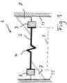
- FIG figure 1 shows a sectional view of an embodiment of a bulkhead part 1, which is positioned in a cavity between two metal sheets 11 of a body.
- the bulkhead part 1 comprises a carrier 2 and expansion material 3 arranged at the edge of the carrier 2.
- the expansion material 3 is shown in FIG figure 1 in an initial state in which it is not yet foamed or expanded.
- the carrier 2 also includes a compensating element 4, which is designed as a spring element.
- the spring element enables linear length changes of the carrier 2 along an axis running on the carrier 2 .
- the effective sealing surface 5 of the carrier 2 is as a projection of the surface of the carrier 2 in the figure 1 drawn.
- a limiting element is in the figure 1 not shown for reasons of clarity. Its function is explained below in connection with the Figures 2 to 4 explained in more detail.
- the bulkhead part 1 is also equipped with two positioning aids 7 .
- the positioning aids 7 are in the form of support ribs which are each arranged on the edges of the carrier 2 .
- the support ribs help to guide the edges of the carrier 2 equipped with expansion material 3 to the metal sheets 11 .
- Each support rib has a support surface that is applied to the respective metal sheet.
- the cavity is sealed with the aid of the bulkhead part 1 as follows:
- the bulkhead part 1 is held in position in the cavity by the positioning aids 7 .
- the expansion material 3 is then activated by heat input.
- the expansion material 3 When the expansion material 3 is activated, it initially expands or foams up and comes into contact with the metal sheets 11 . If the expansion process continues, a force acts on the metal sheets 11 and on the carrier 2.
- the carrier 2 thus reacts to a strong expansion of the expansion material 3 in the course of activation by reducing its effective sealing surface 5, so that the total area sealed by the expansion material 3 and the carrier 2 remains essentially constant and there are no bulges on the outer panels 11 is coming.
- the metal sheets 11 can be prevented from being drawn inwards into the cavity.
- the cooling expansion material 3 at least partially contracts again. Also through this process forces can be effective on the carrier 2 and on the sheets 11, which are now in the are directed in opposite directions. As a reaction to these forces, the compensating element 4 is stretched, as a result of which the effective sealing surface 5 of the carrier 2 becomes larger. The area sealed overall by the expansion material 3 and the carrier 2 thus remains essentially constant in this case as well.
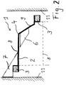
- figure 2 1 shows an alternative exemplary embodiment of a bulkhead part 1.
- the carrier 2 is equipped with a compensation element 4 designed as a film hinge, which is not shown in more detail in the representation of the figure. Due to the film hinge, a movable section 9 can be moved relative to a fixed section 8 of the carrier 2 when the bulkhead part 1 is installed.
- sections 8 and 9 enclose a bending angle of about 120° with one another.
- the movable section 9 can pivot in relation to the fixed section 8 in such a way that the enclosed bending angle increases or decreases.
- a limiting element 6 arranged on the movable section 9 limits the pivoting movement of the section 9 to a small angular range. Pivoting the section 9 away from the right sheet metal 11 very soon leads to the delimiting element 6 striking the fixed section 8. This ensures that the movable section 9 cannot deviate as far as desired in response to an acting force and that the expansion material 3 despite the yielding of the section 9 with sufficient contact pressure on the sheet metal 11 comes to rest, so that a secure and well-sealed connection between the bulkhead part 1 and the sheet metal 11 is produced.
- the pivoting of the movable section 9 relative to the fixed section 8 is accompanied by a change in the effective sealing surface 5 of the carrier 2.
- FIG 3 shows a further exemplary embodiment of the bulkhead part 1 with a compensation element 4 designed as a film hinge figure 2 described.
- a bending angle of approximately 90° is enclosed between the stationary section 8 and the movable section 9 of the carrier 2.
- a delimiting element 6 is arranged on the stationary section 8 of the carrier 2 in this embodiment variant. Accordingly, a pivoting movement of the movable section 9 away from the right sheet metal 11 can only take place up to the stop of the section 9 on the limiting element 6 and is therefore limited to defined angular ranges.
- the effective sealing surface 5 of the carrier 2 changes.
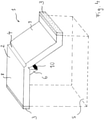
- FIG 4 shows a section of a further embodiment of the bulkhead part 1 in a perspective view.
- the partition part 1 is equipped with a compensation element 4 designed as a film hinge.
- the film hinge forming thin point is in this display clearly visible. Bending of the carrier 2 in the area of the thin point is limited by the limiting element 6, which is arranged here on a stationary section 8 of the carrier 2.
- the delimiting element 6 has an impact edge 10 which can be designed to be shock-absorbing, so that the carrier 2 is not damaged by impact.
- the end figure 4 the importance of the effective sealing surface 5 as the projection surface of the carrier 2 becomes clear once again.
Landscapes
- Engineering & Computer Science (AREA)
- Mechanical Engineering (AREA)
- Chemical & Material Sciences (AREA)
- Combustion & Propulsion (AREA)
- Transportation (AREA)
- Structural Engineering (AREA)
- Architecture (AREA)
- Physics & Mathematics (AREA)
- Acoustics & Sound (AREA)
- Exhaust Gas After Treatment (AREA)
- Gasket Seals (AREA)
- Body Structure For Vehicles (AREA)
- Fluid-Damping Devices (AREA)
- Sealing Material Composition (AREA)
Abstract
Description
- Die Erfindung betrifft ein Schottteil zur Abdichtung und/oder Abstützung eines Hohlraums, umfassend einen Träger sowie ein an dem Träger angeordnetes Expansionsmaterial, welches durch Aktivierung aus einem Ausgangszustand in einen expandierten Zustand überführbar ist.
- Im Automobilbereich werden derartige Schottteile zur akustischen und/oder wasserdichten Abdichtung und Abschottung und/oder Abstützung von Hohlräumen in der Karosserie eingesetzt. Die Schottteile umfassen dabei einen Träger, welcher umlaufend mit einem Expansionsmaterial ausgestattet ist. Das Expansionsmaterial zeichnet sich dadurch aus, dass es im Einbauzustand des Schottteils durch Aktivierung aus einem Ausgangszustand in einen expandierten Zustand überführbar ist, in welchem es als Dichtungs- und/oder Stützmaterial zwischen dem Träger und angrenzenden Komponenten der Karosserie wirkt.
- Aufgrund des Bestrebens der Automobilindustrie, das Gewicht von Fahrzeugen möglichst gering zu halten, werden insbesondere für die Außenhaut der Fahrzeuge immer dünnere Bleche verwendet. Dies hat zur Folge, dass durch Schottteile der eingangs genannten Art, welche zwischen der Außenhaut und einer innenliegenden Komponente, beispielsweise einem weiteren Blech, verbaut werden, Abzeichnungen auf der Außenhaut in Form von Eindellungen nach innen oder Ausbeulungen nach außen sichtbar werden können. Die Ursache hierfür liegt im Wesentlichen in dem Verhalten des Expansionsmaterials, welches sich während des Expansionsvorgangs beispielsweise unter Wärmeeintrag ausdehnt und abdichtend und/oder abstützend an den umgebenden Komponenten zur Anlage kommt. Nach erfolgter Expansion kühlt das Expansionsmaterial wieder ab und zieht sich zumindest teilweise zusammen. Abhängig von den verwendeten Materialien für den Träger und das Expansionsmaterial und der Menge des Expansionsmaterials können durch eine zu starke Ausdehnung des Expansionsmaterials Ausbeulungen des dünnen Außenblechs nach außen bzw. durch das Zusammenziehen des abkühlenden Expansionsmaterials ein Einzug des Außenblechs nach innen verursacht werden. Dies stellt einen optischen Makel dar.
- Grundsätzlich ist es möglich, das Expansions- und Verformungsverhalten und damit Eindellungen nach innen oder Ausbeulungen nach außen durch die Materialauswahl sowie durch maßliche Auslegung der beteiligten Bauteile zu beeinflussen. Dabei verbleibt stets ein Restrisiko, da es sich um ein komplexes System mit zahlreichen Einflussgrößen handelt. Dieser Zustand erscheint verbesserungswürdig.
- Die vorliegende Erfindung hat es sich daher zur Aufgabe gemacht, ein Schottteil zur Abdichtung und/oder Abstützung eines Hohlraums im Karosseriebau bereitzustellen, welches einfach herzustellen ist, im Einbauzustand eine sehr gute Abdichtung gegenüber Geräuschen und Feuchtigkeit bietet und durch welches ein Einzug bzw. eine Ausbeulung einer an das Schottteil angrenzenden Komponente, insbesondere eines Außenblechs, verhindert werden kann.
- Diese Aufgabe wird gelöst durch ein Schottteil mit den Merkmalen des Patentanspruchs 1.
- Vorteilhafte Ausgestaltungen und Weiterbildungen der Erfindung sind Gegenstand der abhängigen Ansprüche.
- Zur Lösung der Aufgabe wird gemäß Patentanspruch 1 vorgeschlagen, dass der Träger mindestens ein Ausgleichselement umfasst, durch welches eine Veränderlichkeit der effektiven Abdichtungsfläche des Trägers gegeben ist, derart, dass durch eine auf den Träger wirkende Kraft eine Veränderung der effektiven Abdichtungsfläche des Trägers bewirkbar ist, wobei ein Begrenzungselement vorgesehen ist, durch welches eine mit der Veränderung der effektiven Abdichtungsfläche einhergehende Bewegung zumindest eines Abschnitts des Trägers begrenzt wird.
- Das erfindungsgemäße Schottteil wird zur Abdichtung eines Hohlraums verwendet und wird hierzu in eine den Hohlraum begrenzende Fläche eingesetzt. Die den Hohlraum begrenzende Fläche, welche es abzudichten gilt, wird im Folgenden auch als Begrenzungsfläche bezeichnet. Zur Abdichtung der Begrenzungsfläche trägt im Einbauzustand des Schottteils sowohl der Träger als auch das Expansionsmaterial des Schottteils bei. Unter der effektiven Abdichtungsfläche des Trägers wird dabei im Sinne der Erfindung eine Projektionsfläche des Trägers verstanden, welche im Einbauzustand des Schottteils in der Ebene der Begrenzungsfläche oder parallel zu dieser liegt. Analog dazu ist mit der effektiven Abdichtungsfläche des Schottteils die Projektionsfläche des gesamten Schottteils bezeichnet, die im Einbauzustand die gesamte Begrenzungsfläche abdeckt und effektiv abdichtet.
- Grundsätzlich umfasst die Erfindung dabei auch Schotteile, die nicht primär abdichtende sondern beispielsweise vorrangig abstützende Wirkung haben. So sind Anwendungsbereiche denkbar, in denen die Anforderungen an eine akustische Abdichtung gering sind und die Begrenzungsfläche entsprechend nicht vollflächig abgedeckt werden muss. Auch hier kann ein erfindungsgemäßes Schottteil eingesetzt werden, welches dann primär abstützende Wirkung hat, gleichzeitig aber Bereiche aufweisen kann, welche für Schallwellen durchlässig sind.
- Mit anderen Worten sieht die Erfindung gemäß Patentanspruch 1 vor, dass der Träger ein Ausgleichselement umfasst, durch welches der Träger auslegbar ist, derart, dass sich die effektive Abdichtungsfläche des Trägers als Reaktion auf eine auf den Träger wirkende Kraft flexibel verändern kann. Eine Kraftwirkung auf den Träger kann dabei in einem Einbauzustand des Schottteils durch das Expansionsverhalten des Expansionsmaterials hervorgerufen werden. Bei Aktivierung des randseitig an dem Träger angeordneten Expansionsmaterials dehnt dieses sich zunächst aus bzw. schäumt auf, bis es an den den Hohlraum begrenzenden Komponenten zur Anlage kommt. Abhängig von den verwendeten Materialien und der Menge an Expansionsmaterial kann die Expansionswirkung dabei so stark sein, dass eine merkliche Kraft auf die umliegenden Komponenten sowie auf den Träger wirkt. Um ein Ausweichen der umliegenden Komponenten, beispielsweise ein Ausbeulen eines Außenblechs nach außen, als Reaktion auf diese Kraft zu verhindern, ist es erfindungsgemäß vorgesehen, dass sich die effektive Abdichtungsfläche des Trägers ändern kann. Zu diesem Zweck weist der Träger mindestens ein Ausgleichselement auf, durch welches eine Veränderlichkeit der effektiven Abdichtungsfläche des Trägers gegeben ist und damit ein Distanzausgleich zugelassen wird. Auf eine starke Ausdehnung des Expansionsmaterials im Zuge der Aktivierung kann der Träger somit mit einer Veränderung, in diesem Falle mit einer Verkleinerung, seiner effektiven Abdichtungsfläche reagieren, so dass die durch das Expansionsmaterial und den Träger insgesamt abgedichtete Fläche im Wesentlichen konstant bleibt und es zu keinerlei Ausbeulungen an umgebenden Komponenten kommt.
- Analog kann im Zuge der Abkühlung und des Zusammenziehens des Expansionsmaterials eine Kraft auf den Träger sowie auf umliegende Komponenten wirken, die einen Einzug nach innen hervorrufen kann. Auch hier wirkt die erfindungsgemäß vorgesehene Veränderlichkeit der effektiven Abdichtungsfläche des Trägers entgegen, indem der Träger als Reaktion auf die wirkenden Kräfte seine effektive Abdichtungsfläche vergrößert, so dass die durch das Expansionsmaterial und den Träger insgesamt abgedichtete Fläche im Wesentlichen wiederum konstant bleibt und es zu keinerlei Einzug an umgebenden Komponenten kommt.
- Das Ausgleichselement, durch welches die Veränderlichkeit der effektiven Abdichtungsfläche des Trägers gegeben ist, kann dabei jeweils so ausgebildet sein, dass in einem Einbauzustand des Schottteils der Schwellenwert der Kraft, bei welchem eine Änderung der effektiven Abdichtungsfläche des Trägers eintritt, niedriger liegt, als ein Schwellenwert, ab dem es zu einem Ausweichen umliegender, den Hohlraum begrenzender Komponenten kommt. Mit anderen Worten kann das Ausgleichselement leicht beweglich ausgebildet sein.
- Zur Begrenzung einer mit der Veränderung der effektiven Abdichtungsfläche des Trägers einhergehenden Bewegung zumindest eines Abschnitts des Trägers sieht die Erfindung ein Begrenzungselement vor. Hierdurch wird sichergestellt, dass der Träger nicht beliebig weit nachgeben kann und dass das Expansionsmaterial trotz des Nachgebens des Trägers als Reaktion auf eine wirkende Kraft mit ausreichendem Anpressdruck an den den Hohlraum begrenzenden Komponenten zur Anlage kommt, so dass eine sichere und gut abdichtende bzw. abstützende Verbindung zwischen dem Schottteil und den begrenzenden Komponenten hergestellt wird.
- Im Einbauzustand gewährleistet ein abdichtend ausgebildetes Schottteil eine sehr gute Abdichtung des Hohlraums gegenüber Wärme, Feuchtigkeit und Geräuschen. Auch Schmutz, Staub oder andere Arten von Partikeln können nicht durch das Schottteil dringen.
- Das Ausgleichselement kann dabei in Form eines Federelements oder einer biegsamen Bauteilkomponente realisiert sein, die bei einer Kraftwirkung auf den Träger eine Aufweitung oder Verkleinerung der effektiven Abdichtungsfläche des Trägers bewirken kann. Beispielsweise können ein feststehender Abschnitt und ein beweglicher Abschnitt des Trägers über das Ausgleichselement derart miteinander verbunden sein, dass der bewegliche Abschnitt durch das Ausgleichselement von dem feststehenden Abschnitt entkoppelt ist. Somit kann der bewegliche Abschnitt in definierbaren Grenzen bewegt werden, ohne dass sich der feststehende Abschnitt bewegt. Das Ausgleichselement ist Teil des Trägers und hat vorzugsweise gleiche abdichtende Eigenschaften wie der Träger.
- Gemäß einer Ausgestaltung der Erfindung ist das Ausgleichselement als Biegeelement ausgebildet, durch welches ein Biegewinkel zwischen zwei Abschnitten des Trägers eingeschlossen wird. Bei dem Biegeelement kann es sich beispielsweise um eine Knickstelle, ein Scharnier, ein Federelement oder eine dazu ähnliche Vorrichtung handeln, die den Träger zu einer Biegebewegung befähigt. Die Biegung erfolgt dabei um eine Biegeachse, welche vorzugsweise parallel zu der Begrenzungsfläche liegt. Der zwischen zwei Abschnitten des Trägers eingeschlossene Biegewinkel kann in einem Bereich zwischen 0° und 180° liegen.
- Nach einer weiteren Ausgestaltung der Erfindung ist das Ausgleichselement als Dünnstelle ausgebildet. Als eine Dünnstelle ist ein Bereich des Trägers definiert, in welchem der Träger dünner ausgebildet ist als in an diesen Bereich angrenzenden Bereichen. Ein solcher, beispielsweise nach Art eines Filmscharniers ausgebildeter Bereich, weist eine vorteilhafte Biegefähigkeiten auf. Der gesamte Träger einschließlich der Dünnstelle kann aus einem einheitlichen Material gefertigt sein, beispielsweise in einem Spritzgussverfahren.
- Das Ausgleichselement kann mit vorteilhaften temperatur- und zeitabhängigen Eigenschaften ausgestattet sein und kann beispielsweise so ausgelegt sein, dass es zeitlich schnell reagiert. So kann das Ausgleichselement sehr schnell eine Veränderung der effektiven Abdichtungsfläche des Trägers, die durch schnelles Aufschäumen und/oder Zusammenziehen des Expansionsmaterials verursacht wird, bewirken.
- Eine Kraft, die auf den Träger wirkt, so dass eine Veränderung der effektiven Abdichtungsfläche des Trägers notwendig ist, kann verschiedene Ursachen haben. In erster Linie entsteht die Kraft durch das Aufschäumen und/oder Zusammenziehen des Expansionsmaterials. Weiterhin kann diese Kraft durch temperaturbedingte Verformung des Trägers und/oder der Umgebung oder des Expansionsmaterials entstehen.
- Der Träger kann in erster Linie die Aufgabe haben, die durch einen Hohlraum aufgespannte Begrenzungsfläche abzudichten. Der Träger deckt dabei vorzugsweise den größten Teil der Begrenzungsfläche ab. Den verbleibenden Teil der Begrenzungsfläche deckt das Expansionsmaterial ab.
- Der Träger kann aus einem Material gefertigt sein, das vorteilhafte abdichtende Eigenschaften aufweist. Das Material kann so gewählt sein, dass es optimale Abdichtungen gegen Wasser, Öl und/oder ähnlichen Flüssigkeiten aufweist. Zudem kann ein leichtes, stabiles und/oder bruchsicheres Material ausgewählt werden. Der Träger kann zur Strukturstabilität des Gesamtobjektes beitragen. So kann der Träger für den Einsatz in Hohlräumen eines Automobils für mehr statische und dynamische Stabilität sorgen. Für den Fall, dass der Hohlraum kollabiert, beispielweise durch einen Unfall, kann das Trägermaterial so ausgewählt werden, dass es vorteilhafte Materialeigenschaften aufweist. Beispielsweise kann das Trägermaterial so ausgewählt sein, dass im Falle der Zerstörung ein Großteil der Verformungsenergie durch den Träger dissipiert. So kann das Material so gewählt sein, dass der Träger bei Zerstörung beispielweise in feinste Einzelteile zerbricht oder sich vorteilhaft deformiert. Das Material ist vorzugsweise so ausgewählt, dass Schäden im Hohlraum oder den benachbarten Regionen, wie beispielsweise der Kabine eines Automobils, verhindert werden.
- Weiterhin kann das Trägermaterial so gewählt werden, dass Eigenschwingen und/oder Körperschall minimiert werden. Es kann sich dabei um Eigenschwingung des Trägers oder des geamten Systems handeln, in welchem der Hohlraum ausgebildet ist. Ebenfalls kann das Trägermaterial optimale schallabweisende Eigenschaften aufweisen. Das Trägermaterial kann isolierend gegenüber Schallwellen und elektromagnetischen Wellen wirken. Als Trägermaterial kann beispielsweise ein Polymermaterial verwendet werden.
- Das Expansionsmaterial ist selbst ein Teil des Schottteils. Dabei kann es vorgesehen sein, dass der Träger umlaufend mit Expansionsmaterial versehen ist, beispielsweise durch Umspritzen. Das Expansionsmaterial hat grundsätzlich zwei Funktionen. Zum einen dient es im expandierten Zustand zur Fixierung des Schottteils in einem Hohlraum, beispielsweise durch Verkleben oder Verklemmen. Zum anderen dient das Expansionsmaterial zusammen mit dem Träger zum Abdichten der Begrenzungsfläche des Hohlraums. Das Expansionsmaterial füllt dabei im expandierten Zustand den Bereich aus, der sich zwischen dem Träger und den den Hohlraum begrenzenden Komponenten ergibt. Das Expansionsmaterial kann dabei vorteilhafterweise anhaftende und/oder klebende Eigenschaften aufweisen. Außerdem kann das Expansionsmaterial elastische Eigenschaften aufweisen. Dabei kann das Expansionsmaterial optimale für den Fall angepasste abdichtende Eigenschaften gegenüber Feuchtigkeit und Geräuschen aufweisen.
- Das Expansionsmaterial kann beispielsweise ein Material sein, welches bei Aktivierung aufschäumt und sich in aufgeschäumtem Zustand verfestigt. Es kann sich dabei beispielsweise um ein Produkt aus der unter dem Namen Teroson® bekannten Produktreihe handeln. Das Volumen des expandierten Expansionsmaterial kann etwa 10% bis 3000% des Volumens des Expansionsmaterials im Ausgangszustand betragen. Es ist möglich, dass das Expansionsmaterial nach der Aktivierung zunächst expandiert und sich nach Erreichen des maximalen Volumens zumindest teilweise wieder zusammenzieht.
- Die Aktivierung des Expansionsmaterials kann vorzugsweise durch Wärmeeintrag erfolgen. Alternativ sind auch andere physikalische und/oder chemische Aktivierungsformen denkbar.
- Durch das erfindungsgemäß vorgesehene Begrenzungselement wird eine mit der Veränderung der effektiven Abdichtungsfläche des Trägers einhergehenden Bewegung zumindest eines Abschnitts des Trägers begrenzt. Mit anderen Worten kann der Träger als Reaktion auf eine wirkende Kraft nicht beliebig nachgeben. Auf diese Weise ist gewährleistet, dass das Expansionsmaterial in jedem Fall mit einem ausreichenden Anpressdruck an den den Hohlraum begrenzenden Komponenten zur Anlage kommt, so dass eine sichere und gut abdichtende Verbindung zwischen dem Schottteil und den begrenzenden Komponenten hergestellt wird.
- Eine Ausgestaltung der Erfindung sieht vor, dass das Begrenzungselement an einem feststehenden Abschnitt des Trägers angeordnet ist. Unter einem feststehenden Abschnitt wird dabei ein Abschnitt des Trägers verstanden, welcher in einem Einbauzustand des Schotteils im Zuge der Veränderung der effektiven Abdichtungsfläche des Trägers seine Position im Wesentlichen nicht ändert. Demgegenüber wird unter einem beweglichen Abschnitt des Trägers ein Abschnitt verstanden, welcher in einem Einbauzustand des Schottteils im Zuge der Veränderung der effektiven Abdichtungsfläche des Trägers seine Position ändert. Das Begrenzungselement kann in einer alternativen Ausgestaltung auch an einem beweglichen Abschnitt des Trägers angeordnet sein. Das Begrenzungselement wirkt dabei jeweils als in einen Zwischenraum zwischen einem beweglichen und einem feststehenden Abschnitt eingebrachter Anschlag, derart, dass eine Bewegung eines beweglichen Abschnitts gegenüber einem feststehenden Abschnitt durch das Begrenzungselement auf eine kleine Bewegung begrenzt ist.
- Bei einer Ausgestaltung des Ausgleichselements als Biegeelement mit einem zwischen zwei Abschnitten des Trägers eingeschlossenen Biegewinkel kann das Begrenzungselement derart an einem der beiden Abschnitte angeordnet sein, dass eine Bewegung des einen Abschnitts gegenüber dem zweiten Abschnitt nur über einen begrenzten Winkelbereich des Biegewinkels erfolgen kann. Beispielsweise kann das Begrenzungselement so gestaltet sein, dass eine Bewegung des einen Abschnitts gegenüber dem anderen Abschnitt lediglich über einen Winkelbereich von 0° bis 20° erfolgen kann, während größere Winkelbewegungen durch das Begrenzungselement verhindert werden. Das Begrenzungselement kann stoßdämpfend ausgelegt sein, so dass durch das Anstoßen kein Schaden am Schottteil entsteht. Weiterhin kann das Begrenzungselement eine Anstoßkante aufweisen, das die zuvor erklärte stoßdämpfende Funktion übernimmt.
- Das Begrenzungselement kann grundsätzlich verschiedene Querschnitte ausweisen. Beispielsweise kann das Begrenzungselement einen dreieckigen oder einen trapezförmigen Querschnitt aufweisen.
- Eine Ausführungsvariante der Erfindung sieht vor, dass das Schottteil mit mindestens einer Positionierhilfe ausgerüstet ist, wobei die Positionierhilfe eine Stützrippe umfasst, die ein Mittel zur Positionierung des Trägers aufweist. Die Positionierhilfe unterstützt bei einer exakten Positionierung und Abstützung des Schottteils in einem Hohlraum und stellt sicher, dass das Schottteil nach seiner Montage in der gewünschten Ausrichtung verbleibt. Die Positionierhilfe kann dabei so gestaltet sein, dass eine Stützfläche der Positionierhilfe bündig an einer den Hohlraum begrenzenden Wandung anliegt.
- Zusammenfassend ist mit dem beschriebenen Schottteil eine sehr gute Abdichtung eines Hohlraums gegenüber Feuchtigkeit und Geräuschen und/oder eine Abstützung möglich, wobei die erfindungsgemäß vorgesehene Veränderlichkeit der effektiven Abdichtungsfläche des Trägers zu einer Entkopplung von Zug- bzw. Druckkräften führt, derart, dass im Zuge der Aktivierung des Expansionsmaterials keine bzw. keine wesentlichen Kräfte auf angrenzende Komponenten wirken und ein Ausbeulen und/oder Einzug dieser Konponenten wirksam verhindert werden kann. Hierdurch bestehen mehr Freiheiten bei der Auswahl des Materials für das Trägermaterial und das Expansionsmaterial. Durch das erfindungsgemäß vorgesehene Begrenzungselement ist darüber hinaus trotz der Nachgiebigkeit des Trägers eine ausreichende Dichtigkeit gegenüber Feuchtigkeit und Schall im Anschlussbereich des Schottteils gegeben.
- Im Folgenden wird die Erfindung anhand von Ausführungsbeispielen und unter Bezugnahme auf die beigefügten Zeichnungen näher erläutert. Es zeigen:
- Figur 1:
- ein Ausführungsbeispiel des erfindungsgemäßen Schottteils in einer Schnittdarstellung;
- Figur 2:
- ein weiteres Ausführungsbeispiel des Schottteils in einer Schnittdarstellung;
- Figur 3:
- ein weiteres Ausführungsbeispiel des Schottteils in einer Schnittdarstellung;
- Figur 4:
- ein weiteres Ausführungsbeispiel des Schottteils in einer perspektivischen Ansicht.
-
Figur 1 zeigt in einer Schnittdarstellung ein Ausführungsbeispiel eines Schottteils 1, welches in einem Hohlraum zwischen zwei Blechen 11 einer Karosserie positioniert ist. Das Schottteil 1 umfasst einen Träger 2 sowie randseitig an dem Träger 2 angeordnetes Expansionsmaterial 3. Das Expansionsmaterial 3 befindet sich in der Darstellung derFigur 1 in einem Ausgangszustand, in dem es noch nicht aufgeschäumt bzw. expandiert ist. - Der Träger 2 umfasst weiterhin ein Ausgleichselement 4, welches als Federelement ausgebildet ist. Das Federelement ermöglicht lineare Längenänderungen des Trägers 2 entlang einer auf dem Träger 2 verlaufenden Achse. Dadurch kann sich als Reaktion auf eine auf den Träger 2 wirkende Kraft die Länge des Trägers 2 entlang dieser Achse und damit die effektive Abdichtungsfläche 5 des Trägers 2 ändern. Die effektive Abdichtungsfläche 5 des Trägers 2 ist als Projektionsfläche der Fläche des Trägers 2 in der
Figur 1 eingezeichnet. - Ein Begrenzungselement ist in der
Figur 1 aus Gründen der Übersichtlichkeit nicht eingezeichnet. Dessen Funktion wird unten im Zusammenhang mit denFiguren 2 bis 4 genauer erläutert. - Das Schottteil 1 ist darüber hinaus mit zwei Positionierhilfen 7 ausgerüstet. Die Positionierhilfen 7 sind dabei als Stützrippen ausgestaltet, die jeweils an den Rändern des Trägers 2 angeordnet sind. Hierbei helfen die Stützrippen dabei, die mit Expansionsmaterial 3 ausgestatteten Ränder des Trägers 2 an die Bleche 11 zu führen. Jede Stützrippe hat dabei eine Stützfläche, die an das jeweilige Blech angelegt wird.
- Die Abdichtung des Hohlraums mithilfe des Schottteils 1 erfolgt folgendermaßen: Das Schottteil 1 wird durch die Positionierhilfen 7 in dem Hohlraum in Position gehalten. Daraufhin wird das Expansionsmaterial 3 durch Wärmeeintrag aktiviert. Bei Aktivierung des Expansionsmaterials 3 dehnt sich dieses zunächst aus bzw. schäumt auf, und kommt an den Blechen 11 zur Anlage. Bei anhaltendem Expansionsprozess wirkt eine Kraft auf die Bleche 11 sowie auf den Träger 2. Als Reaktion auf diese Kraftwirkung reagiert das als Federelement ausgebildete Ausgleichselement 4 und wird zusammengedrückt. Hierdurch ändert sich die effektive Abdichtungsfläche 5 des Trägers 2, sie wird kleiner. Mit anderen Worten wird durch den Träger 2 ein Distanzausgleich geschaffen, derart, dass ein Ausweichen bzw. Ausbeulen der Bleche 11 nach außen verhindert werden kann. Auf eine starke Ausdehnung des Expansionsmaterials 3 im Zuge der Aktivierung reagiert der Träger 2 somit mit einer Verkleinerung seiner effektiven Abdichtungsfläche 5, so dass die durch das Expansionsmaterial 3 und den Träger 2 insgesamt abgedichtete Fläche im Wesentlichen konstant bleibt und es zu keinerlei Ausbeulungen an den Außenblechen 11 kommt.
- Ebenso kann nach erfolgter Aktivierung während des Abkühlens des Expansionsmaterials ein Einzug der Bleche 11 nach Innen in den Hohlraum hinein verhindert werden. Das abkühlende Expansionsmaterial 3 zieht sich zumindest teilweise wieder zusammen. Auch durch diesen Prozess können Kräfte auf den Träger 2 sowie auf die Bleche 11 wirksam werden, die nun in die entgegengesetzte Richtung gerichtet sind. Als Reaktion auf diese Kraftwirkungen wird das Ausgleichselement 4 gedehnt, wodurch die effektive Abdichtungsfläche 5 des Trägers 2 größer wird. Die durch das Expansionsmaterial 3 und den Träger 2 insgesamt abgedichtete Fläche bleibt damit auch in diesem Fall im Wesentlichen konstant.
-
Figur 2 zeigt ein alternatives Ausführungsbeispiel eines Schottteils 1. Hierbei ist der Träger 2 mit einem als Filmscharnier ausgebildeten Ausgleichselement 4 ausgerüstet, welches in der Darstellung der Figur nicht genauer dargestellt ist. Durch das Filmscharnier ist in einem Einbauzustand des Schottteils 1 ein beweglicher Abschnitt 9 gegenüber einem feststehenden Abschnitt 8 des Trägers 2 beweglich. In dem in derFigur 2 dargestellten Zustand schließen die Abschnitte 8 und 9 einen Biegewinkel von etwa 120° miteinander ein. Als Reaktion auf eine durch das Expansionsverhalten des Expansionsmaterials 3 hervorgerufene Kraftwirkung auf den Träger 2 kann der bewegliche Abschnitt 9 gegenüber dem feststehenden Abschnitt 8 derart verschwenken, dass sich der eingeschlossene Biegewinkel vergrößert oder verkleinert. Bei einer Verkleinerung des Biegewinkels begrenzt ein an dem beweglichen Abschnitt 9 angeordnetes Begrenzungselement 6 die Schwenkbewegung des Abschnitts 9 auf einen kleinen Winkelbereich. Ein Schwenken des Abschnitts 9 von dem rechten Blech 11 weg führt sehr bald zum Anschlag des Begrenzungselements 6 an dem feststehenden Abschnitt 8. Hierdurch wird sichergestellt, dass der bewegliche Abschnitt 9 als Reaktion auf eine wirkende Kraft nicht beliebig weit ausweichen kann und dass das Expansionsmaterial 3 trotz des Nachgebens des Abschnitts 9 mit ausreichendem Anpressdruck an dem Blech 11 zur Anlage kommt, so dass eine sichere und gut abdichtende Verbindung zwischen dem Schottteil 1 und dem Blech 11 hergestellt wird. Das Verschwenken des beweglichen Abschnitts 9 gegenüber dem feststehenden Abschnitt 8 geht mit einer Änderung der effektiven Abdichtungsfläche 5 des Trägers 2 einher. -
Figur 3 zeigt ein weiteres Ausführungsbeispiel des Schottteils 1 mit einem als Filmscharnier ausgebildeten Ausgleichselement 4. Die Funktionsweise entspricht grundsätzlich der im Zusammenhang mitFigur 2 beschriebenen. In dem hier dargestellten Ausgangszustand wird ein Biegewinkel von etwa 90° zwischen dem feststehenden Abschnitt 8 und dem beweglichen Abschnitt 9 des Trägers 2 eingeschlossen. Ein Begrenzungselement 6 ist bei dieser Ausführungsvariante an dem feststehenden Abschnitt 8 des Trägers 2 angeordnet. Entsprechend kann eine Schwenkbewegung des beweglichen Abschnitts 9 von dem rechten Blech 11 weg nur bis zum Anschlag des Abschnitts 9 an dem Begrenzungselement 6 erfolgen und ist damit auf definierte Winkelbereiche begrenzt. Durch Verschwenken des beweglichen Abschnitts 9 gegenüber dem feststehenden Abschnitt 8 als Reaktion auf eine wirkende Kraft ändert sich die effektive Abdichtungsfläche 5 des Trägers 2. -
Figur 4 zeigt einen Ausschnitt eines weiteren Ausführungsbeispiels des Schottteils 1 in perspektivischer Ansicht. Auch hier ist das Schottteil 1 mit einem als Filmscharnier ausgebildeten Ausgleichselement 4 ausgerüstet. Die das Filmscharnier bildende Dünnstelle ist in dieser Darstellung gut zu erkennen. Eine Biegung des Trägers 2 im Bereich der Dünnstelle ist durch das Begrenzungselement 6, welches hier an einem feststehenden Abschnitt 8 des Trägers 2 angeordnet ist, begrenzt. Das Begrenzungselement 6 weist eine Anstoßkante 10 auf, die stoßdämpfend ausgelegt sein kann, so dass durch das Anstoßen kein Schaden am Träger 2 entsteht. AusFigur 4 wird darüber hinaus die Bedeutung der effektiven Abdichtungsfläche 5 als Projektionsfläche des Trägers 2 nochmals deutlich. -
- 1
- Schottteil
- 2
- Träger
- 3
- Expansionsmaterial
- 4
- Ausgleichselement
- 5
- Effektive Abdichtungsfläche
- 6
- Begrenzungselement
- 7
- Positionierhilfe
- 8
- Feststehender Abschnitt
- 9
- Beweglicher Abschnitt
- 10
- Anstoßkante
- 11
- Blech
Claims (7)
- Schottteil (1) zur Abdichtung und/oder Abstützung eines Hohlraums, umfassend einen Träger (2) sowie ein an dem Träger (2) angeordnetes Expansionsmaterial (3), welches durch Aktivierung aus einem Ausgangszustand in einen expandierten Zustand überführbar ist, dadurch gekennzeichnet, dass der Träger (2) mindestens ein Ausgleichselement (4) umfasst, durch welches eine Veränderlichkeit der effektiven Abdichtungsfläche (5) des Trägers (2) gegeben ist, derart, dass durch eine auf den Träger (2) wirkende Kraft eine Veränderung der effektiven Abdichtungsfläche (5) des Trägers (2) bewirkbar ist, wobei ein Begrenzungselement (6) vorgesehen ist, durch welches eine mit der Veränderung der effektiven Abdichtungsfläche (5) einhergehende Bewegung zumindest eines Abschnitts des Trägers (2) begrenzt wird.
- Schottteil (1) nach Anspruch 1, dadurch gekennzeichnet, dass das Ausgleichselement (4) als Biegeelement ausgebildet ist, durch welches ein Biegewinkel zwischen zwei Abschnitten des Trägers (2) eingeschlossen wird.
- Schottteil (1) nach einem der Ansprüche 1 oder 2, dadurch gekennzeichnet, dass das Ausgleichselement (4) als Dünnstelle ausgebildet ist.
- Schottteil (1) nach einem der Ansprüche 1 bis 3, dadurch gekennzeichnet, dass das Begrenzungselement (6) an einem feststehenden Abschnitt (8) des Trägers (2) angeordnet ist.
- Schottteil (1) nach einem der Ansprüche 1 bis 3, dadurch gekennzeichnet, dass das Begrenzungselement (6) an einem beweglichen Abschnitt (9) des Trägers (2) angeordnet ist.
- Schottteil (1) nach einem der Ansprüche 1 bis 5, dadurch gekennzeichnet, dass das Schottteil (1) mit mindestens einer Positionierhilfe (7) ausgerüstet ist, wobei die Positionierhilfe (7) eine Stützrippe umfasst, die ein Element zur Positionierung des Trägers (2) aufweist.
- Schottteil (1) nach einem der Ansprüche 1 bis 6, dadurch gekennzeichnet, dass das Begrenzungselement (6) eine Anstoßkante (10) umfasst, welche stoßdämpfend ausgebildet ist.
Priority Applications (7)
| Application Number | Priority Date | Filing Date | Title |
|---|---|---|---|
| EP20193282.9A EP3960591B1 (de) | 2020-08-28 | 2020-08-28 | Schotteil |
| ES20193282T ES2992533T3 (es) | 2020-08-28 | 2020-08-28 | Pieza de mamparo |
| PCT/EP2021/073629 WO2022043447A1 (de) | 2020-08-28 | 2021-08-26 | Schottteil |
| CN202180052921.0A CN115989173A (zh) | 2020-08-28 | 2021-08-26 | 隔板 |
| JP2023513690A JP2023539294A (ja) | 2020-08-28 | 2021-08-26 | パーティション |
| KR1020237006165A KR20230054832A (ko) | 2020-08-28 | 2021-08-26 | 파티션 |
| US18/172,635 US12466339B2 (en) | 2020-08-28 | 2023-02-22 | Partition |
Applications Claiming Priority (1)
| Application Number | Priority Date | Filing Date | Title |
|---|---|---|---|
| EP20193282.9A EP3960591B1 (de) | 2020-08-28 | 2020-08-28 | Schotteil |
Publications (2)
| Publication Number | Publication Date |
|---|---|
| EP3960591A1 true EP3960591A1 (de) | 2022-03-02 |
| EP3960591B1 EP3960591B1 (de) | 2024-06-12 |
Family
ID=72355746
Family Applications (1)
| Application Number | Title | Priority Date | Filing Date |
|---|---|---|---|
| EP20193282.9A Active EP3960591B1 (de) | 2020-08-28 | 2020-08-28 | Schotteil |
Country Status (7)
| Country | Link |
|---|---|
| US (1) | US12466339B2 (de) |
| EP (1) | EP3960591B1 (de) |
| JP (1) | JP2023539294A (de) |
| KR (1) | KR20230054832A (de) |
| CN (1) | CN115989173A (de) |
| ES (1) | ES2992533T3 (de) |
| WO (1) | WO2022043447A1 (de) |
Families Citing this family (1)
| Publication number | Priority date | Publication date | Assignee | Title |
|---|---|---|---|---|
| ES2992533T3 (es) * | 2020-08-28 | 2024-12-13 | Henkel Ag & Co Kgaa | Pieza de mamparo |
Citations (5)
| Publication number | Priority date | Publication date | Assignee | Title |
|---|---|---|---|---|
| US5631027A (en) * | 1995-07-31 | 1997-05-20 | Neo-Ex Lab, Inc. | Support structure for supporting foamable material on hollow structural member |
| DE29522122U1 (de) * | 1994-03-14 | 1999-11-18 | Magna Exterior Systems GmbH, 63179 Obertshausen | Verbundwerkstoff |
| DE10240196A1 (de) * | 2002-08-28 | 2004-03-11 | Henkel Kgaa | Verfahren zum Fixieren von Schottteilen und Bauteile hierfür |
| WO2010014681A2 (en) * | 2008-07-29 | 2010-02-04 | Henkel Ag & Co. Kgaa | Reinforcement assembly |
| US20130241226A1 (en) * | 2012-03-13 | 2013-09-19 | Zephyros, Inc. | Load actuated baffle |
Family Cites Families (21)
| Publication number | Priority date | Publication date | Assignee | Title |
|---|---|---|---|---|
| EP0679501A1 (de) * | 1994-03-14 | 1995-11-02 | YMOS AKTIENGESELLSCHAFT Industrieprodukte | Verbundmaterial mit schaumfähigem Kern |
| US5506025A (en) * | 1995-01-09 | 1996-04-09 | Sika Corporation | Expandable baffle apparatus |
| WO2001024989A1 (en) * | 1999-10-04 | 2001-04-12 | Tyco Electronics Corporation | Cavity sealing article with articulated support |
| FR2826621B1 (fr) * | 2001-07-02 | 2003-09-26 | Hutchinson | Dispositif d'isolation acoustique destine a etre monte dans une piece tubulaire, en particulier d'une piece de carrosserie automobile |
| US6883858B2 (en) * | 2002-09-10 | 2005-04-26 | L & L Products, Inc. | Structural reinforcement member and method of use therefor |
| US7841647B2 (en) | 2006-11-15 | 2010-11-30 | Sika Technology Ag | Baffle assembly |
| US8348581B2 (en) * | 2007-01-18 | 2013-01-08 | Sika Technology Ag | Integral tensioning member for variable sheetmetal thickness carrier attachment |
| DE102007015394A1 (de) | 2007-03-28 | 2008-10-02 | Henkel Ag & Co. Kgaa | Schalldämmendes Schottteil zum Abdichten eines Hohlraumes |
| KR20100051809A (ko) * | 2007-08-16 | 2010-05-18 | 헨켈 아게 운트 코. 카게아아 | 음향 배플 |
| US7735906B2 (en) * | 2007-09-28 | 2010-06-15 | Zephyros, Inc. | Reinforcement system for an automotive vehicle |
| ATE535432T1 (de) * | 2008-08-05 | 2011-12-15 | Sika Technology Ag | Schalldämpfendes schottteil |
| WO2016176459A1 (en) * | 2015-04-30 | 2016-11-03 | Zephyros, Inc. | Members for sealing, baffling, or reinforcing |
| US10695962B2 (en) | 2016-03-18 | 2020-06-30 | Zephyros, Inc. | Members for directing expandable material for baffling, sealing, reinforcing |
| EP3445643A1 (de) * | 2016-04-21 | 2019-02-27 | Zephyros Inc. | Dichtungsvorrichtung für rohrelement |
| US10960934B2 (en) * | 2017-01-23 | 2021-03-30 | Zephyros, Inc. | Pillar reinforcement |
| WO2020043739A1 (de) * | 2018-08-31 | 2020-03-05 | Sika Technology Ag | System zu dämmung eines strukturelementes |
| EP3712041B1 (de) * | 2019-03-19 | 2022-01-19 | Sika Technology Ag | Verstärkungselement |
| EP3747739B1 (de) * | 2019-06-07 | 2025-12-17 | Zephyros Inc. | Universelles hochexpandierbares füllorgan |
| DE102019132868A1 (de) * | 2019-12-03 | 2021-06-10 | Henkel Ag & Co. Kgaa | Schottteil |
| ES2992533T3 (es) * | 2020-08-28 | 2024-12-13 | Henkel Ag & Co Kgaa | Pieza de mamparo |
| EP4227195A1 (de) * | 2022-02-11 | 2023-08-16 | Sika Technology AG | System eines strukturelementes mit darin angeordnetem dämmelement |
-
2020
- 2020-08-28 ES ES20193282T patent/ES2992533T3/es active Active
- 2020-08-28 EP EP20193282.9A patent/EP3960591B1/de active Active
-
2021
- 2021-08-26 KR KR1020237006165A patent/KR20230054832A/ko active Pending
- 2021-08-26 CN CN202180052921.0A patent/CN115989173A/zh active Pending
- 2021-08-26 WO PCT/EP2021/073629 patent/WO2022043447A1/de not_active Ceased
- 2021-08-26 JP JP2023513690A patent/JP2023539294A/ja active Pending
-
2023
- 2023-02-22 US US18/172,635 patent/US12466339B2/en active Active
Patent Citations (5)
| Publication number | Priority date | Publication date | Assignee | Title |
|---|---|---|---|---|
| DE29522122U1 (de) * | 1994-03-14 | 1999-11-18 | Magna Exterior Systems GmbH, 63179 Obertshausen | Verbundwerkstoff |
| US5631027A (en) * | 1995-07-31 | 1997-05-20 | Neo-Ex Lab, Inc. | Support structure for supporting foamable material on hollow structural member |
| DE10240196A1 (de) * | 2002-08-28 | 2004-03-11 | Henkel Kgaa | Verfahren zum Fixieren von Schottteilen und Bauteile hierfür |
| WO2010014681A2 (en) * | 2008-07-29 | 2010-02-04 | Henkel Ag & Co. Kgaa | Reinforcement assembly |
| US20130241226A1 (en) * | 2012-03-13 | 2013-09-19 | Zephyros, Inc. | Load actuated baffle |
Also Published As
| Publication number | Publication date |
|---|---|
| US20230202407A1 (en) | 2023-06-29 |
| ES2992533T3 (es) | 2024-12-13 |
| CN115989173A (zh) | 2023-04-18 |
| EP3960591B1 (de) | 2024-06-12 |
| JP2023539294A (ja) | 2023-09-13 |
| US12466339B2 (en) | 2025-11-11 |
| KR20230054832A (ko) | 2023-04-25 |
| WO2022043447A1 (de) | 2022-03-03 |
Similar Documents
| Publication | Publication Date | Title |
|---|---|---|
| DE3024089C2 (de) | Hydraulisch dämpfendes Lager | |
| DE3840176C2 (de) | ||
| DE3225701A1 (de) | Elastisches gummilager | |
| DE112014004130T5 (de) | Blechverbindungsstruktur | |
| DE102010030535A1 (de) | Kraftfahrzeug mit einem Seitenschweller | |
| DE112015000685T5 (de) | Fahrzeugkarosseriestruktur für ein Fahrzeug | |
| DE102007005371A1 (de) | Rohrdichtungselement und Verfahren zur seiner Herstellung | |
| DE3447424A1 (de) | Fahrzeugstossstange | |
| EP2359025B1 (de) | Hydrolager | |
| DE102011108403A1 (de) | Montageverbund eines Kraftfahrzeugs | |
| EP3960591B1 (de) | Schotteil | |
| DE102022202129A1 (de) | Zuschlag-stossfängervorrichtung für ein fahrzeug | |
| DE2310574A1 (de) | Elastomere halterungen | |
| DE19807949B4 (de) | Hydraulisch gedämpfte Lagereinrichtung | |
| DE102020119230A1 (de) | Antriebsanordnung für eine Klappe eines Kraftfahrzeugs | |
| EP0595160A2 (de) | Stossdämpfer | |
| EP0811785A2 (de) | Hydraulisch dämpfende Hülsengummifeder | |
| DE3921610A1 (de) | Elastische aufhaengung mit einer fluidfuellung | |
| EP3589861A1 (de) | Membran sowie hydraulisch dämpfendes lager | |
| DE10002379A1 (de) | Stoßfänger | |
| DE102004041382B4 (de) | Fahrzeugtür und Tragstruktur für eine Fahrzeugtür | |
| DE102006032633A1 (de) | Hydrobuchsenlager mit akustischer Entkopplung | |
| EP1135627B1 (de) | Hydraulisch dämpfendes gummilager mit entkopplungselement | |
| DE102014222929A1 (de) | Hydrolager sowie Kraftfahrzeug mit einem derartigen Hydrolager | |
| WO2005108830A1 (de) | Dichtung zur abdichtung einer öffnung |
Legal Events
| Date | Code | Title | Description |
|---|---|---|---|
| PUAI | Public reference made under article 153(3) epc to a published international application that has entered the european phase |
Free format text: ORIGINAL CODE: 0009012 |
|
| STAA | Information on the status of an ep patent application or granted ep patent |
Free format text: STATUS: THE APPLICATION HAS BEEN PUBLISHED |
|
| AK | Designated contracting states |
Kind code of ref document: A1 Designated state(s): AL AT BE BG CH CY CZ DE DK EE ES FI FR GB GR HR HU IE IS IT LI LT LU LV MC MK MT NL NO PL PT RO RS SE SI SK SM TR |
|
| STAA | Information on the status of an ep patent application or granted ep patent |
Free format text: STATUS: REQUEST FOR EXAMINATION WAS MADE |
|
| 17P | Request for examination filed |
Effective date: 20220831 |
|
| RBV | Designated contracting states (corrected) |
Designated state(s): AL AT BE BG CH CY CZ DE DK EE ES FI FR GB GR HR HU IE IS IT LI LT LU LV MC MK MT NL NO PL PT RO RS SE SI SK SM TR |
|
| P01 | Opt-out of the competence of the unified patent court (upc) registered |
Effective date: 20230530 |
|
| GRAP | Despatch of communication of intention to grant a patent |
Free format text: ORIGINAL CODE: EPIDOSNIGR1 |
|
| STAA | Information on the status of an ep patent application or granted ep patent |
Free format text: STATUS: GRANT OF PATENT IS INTENDED |
|
| INTG | Intention to grant announced |
Effective date: 20240226 |
|
| GRAS | Grant fee paid |
Free format text: ORIGINAL CODE: EPIDOSNIGR3 |
|
| GRAA | (expected) grant |
Free format text: ORIGINAL CODE: 0009210 |
|
| STAA | Information on the status of an ep patent application or granted ep patent |
Free format text: STATUS: THE PATENT HAS BEEN GRANTED |
|
| AK | Designated contracting states |
Kind code of ref document: B1 Designated state(s): AL AT BE BG CH CY CZ DE DK EE ES FI FR GB GR HR HU IE IS IT LI LT LU LV MC MK MT NL NO PL PT RO RS SE SI SK SM TR |
|
| REG | Reference to a national code |
Ref country code: GB Ref legal event code: FG4D Free format text: NOT ENGLISH |
|
| REG | Reference to a national code |
Ref country code: CH Ref legal event code: EP |
|
| REG | Reference to a national code |
Ref country code: IE Ref legal event code: FG4D Free format text: LANGUAGE OF EP DOCUMENT: GERMAN |
|
| REG | Reference to a national code |
Ref country code: DE Ref legal event code: R096 Ref document number: 502020008254 Country of ref document: DE |
|
| REG | Reference to a national code |
Ref country code: SK Ref legal event code: T3 Ref document number: E 44564 Country of ref document: SK |
|
| PG25 | Lapsed in a contracting state [announced via postgrant information from national office to epo] |
Ref country code: BG Free format text: LAPSE BECAUSE OF FAILURE TO SUBMIT A TRANSLATION OF THE DESCRIPTION OR TO PAY THE FEE WITHIN THE PRESCRIBED TIME-LIMIT Effective date: 20240612 |
|
| PG25 | Lapsed in a contracting state [announced via postgrant information from national office to epo] |
Ref country code: FI Free format text: LAPSE BECAUSE OF FAILURE TO SUBMIT A TRANSLATION OF THE DESCRIPTION OR TO PAY THE FEE WITHIN THE PRESCRIBED TIME-LIMIT Effective date: 20240612 Ref country code: HR Free format text: LAPSE BECAUSE OF FAILURE TO SUBMIT A TRANSLATION OF THE DESCRIPTION OR TO PAY THE FEE WITHIN THE PRESCRIBED TIME-LIMIT Effective date: 20240612 |
|
| REG | Reference to a national code |
Ref country code: LT Ref legal event code: MG9D |
|
| PG25 | Lapsed in a contracting state [announced via postgrant information from national office to epo] |
Ref country code: GR Free format text: LAPSE BECAUSE OF FAILURE TO SUBMIT A TRANSLATION OF THE DESCRIPTION OR TO PAY THE FEE WITHIN THE PRESCRIBED TIME-LIMIT Effective date: 20240913 |
|
| REG | Reference to a national code |
Ref country code: NL Ref legal event code: MP Effective date: 20240612 |
|
| PG25 | Lapsed in a contracting state [announced via postgrant information from national office to epo] |
Ref country code: LV Free format text: LAPSE BECAUSE OF FAILURE TO SUBMIT A TRANSLATION OF THE DESCRIPTION OR TO PAY THE FEE WITHIN THE PRESCRIBED TIME-LIMIT Effective date: 20240612 |
|
| PG25 | Lapsed in a contracting state [announced via postgrant information from national office to epo] |
Ref country code: NO Free format text: LAPSE BECAUSE OF FAILURE TO SUBMIT A TRANSLATION OF THE DESCRIPTION OR TO PAY THE FEE WITHIN THE PRESCRIBED TIME-LIMIT Effective date: 20240912 Ref country code: LV Free format text: LAPSE BECAUSE OF FAILURE TO SUBMIT A TRANSLATION OF THE DESCRIPTION OR TO PAY THE FEE WITHIN THE PRESCRIBED TIME-LIMIT Effective date: 20240612 Ref country code: HR Free format text: LAPSE BECAUSE OF FAILURE TO SUBMIT A TRANSLATION OF THE DESCRIPTION OR TO PAY THE FEE WITHIN THE PRESCRIBED TIME-LIMIT Effective date: 20240612 Ref country code: GR Free format text: LAPSE BECAUSE OF FAILURE TO SUBMIT A TRANSLATION OF THE DESCRIPTION OR TO PAY THE FEE WITHIN THE PRESCRIBED TIME-LIMIT Effective date: 20240913 Ref country code: FI Free format text: LAPSE BECAUSE OF FAILURE TO SUBMIT A TRANSLATION OF THE DESCRIPTION OR TO PAY THE FEE WITHIN THE PRESCRIBED TIME-LIMIT Effective date: 20240612 Ref country code: BG Free format text: LAPSE BECAUSE OF FAILURE TO SUBMIT A TRANSLATION OF THE DESCRIPTION OR TO PAY THE FEE WITHIN THE PRESCRIBED TIME-LIMIT Effective date: 20240612 Ref country code: RS Free format text: LAPSE BECAUSE OF FAILURE TO SUBMIT A TRANSLATION OF THE DESCRIPTION OR TO PAY THE FEE WITHIN THE PRESCRIBED TIME-LIMIT Effective date: 20240912 |
|
| PG25 | Lapsed in a contracting state [announced via postgrant information from national office to epo] |
Ref country code: NL Free format text: LAPSE BECAUSE OF FAILURE TO SUBMIT A TRANSLATION OF THE DESCRIPTION OR TO PAY THE FEE WITHIN THE PRESCRIBED TIME-LIMIT Effective date: 20240612 |
|
| PG25 | Lapsed in a contracting state [announced via postgrant information from national office to epo] |
Ref country code: NL Free format text: LAPSE BECAUSE OF FAILURE TO SUBMIT A TRANSLATION OF THE DESCRIPTION OR TO PAY THE FEE WITHIN THE PRESCRIBED TIME-LIMIT Effective date: 20240612 |
|
| PG25 | Lapsed in a contracting state [announced via postgrant information from national office to epo] |
Ref country code: PT Free format text: LAPSE BECAUSE OF FAILURE TO SUBMIT A TRANSLATION OF THE DESCRIPTION OR TO PAY THE FEE WITHIN THE PRESCRIBED TIME-LIMIT Effective date: 20241014 |
|
| REG | Reference to a national code |
Ref country code: ES Ref legal event code: FG2A Ref document number: 2992533 Country of ref document: ES Kind code of ref document: T3 Effective date: 20241213 |
|
| PG25 | Lapsed in a contracting state [announced via postgrant information from national office to epo] |
Ref country code: PT Free format text: LAPSE BECAUSE OF FAILURE TO SUBMIT A TRANSLATION OF THE DESCRIPTION OR TO PAY THE FEE WITHIN THE PRESCRIBED TIME-LIMIT Effective date: 20241014 |
|
| PG25 | Lapsed in a contracting state [announced via postgrant information from national office to epo] |
Ref country code: PL Free format text: LAPSE BECAUSE OF FAILURE TO SUBMIT A TRANSLATION OF THE DESCRIPTION OR TO PAY THE FEE WITHIN THE PRESCRIBED TIME-LIMIT Effective date: 20240612 |
|
| PG25 | Lapsed in a contracting state [announced via postgrant information from national office to epo] |
Ref country code: EE Free format text: LAPSE BECAUSE OF FAILURE TO SUBMIT A TRANSLATION OF THE DESCRIPTION OR TO PAY THE FEE WITHIN THE PRESCRIBED TIME-LIMIT Effective date: 20240612 |
|
| PG25 | Lapsed in a contracting state [announced via postgrant information from national office to epo] |
Ref country code: IS Free format text: LAPSE BECAUSE OF FAILURE TO SUBMIT A TRANSLATION OF THE DESCRIPTION OR TO PAY THE FEE WITHIN THE PRESCRIBED TIME-LIMIT Effective date: 20241012 |
|
| PG25 | Lapsed in a contracting state [announced via postgrant information from national office to epo] |
Ref country code: RO Free format text: LAPSE BECAUSE OF FAILURE TO SUBMIT A TRANSLATION OF THE DESCRIPTION OR TO PAY THE FEE WITHIN THE PRESCRIBED TIME-LIMIT Effective date: 20240612 |
|
| PG25 | Lapsed in a contracting state [announced via postgrant information from national office to epo] |
Ref country code: SM Free format text: LAPSE BECAUSE OF FAILURE TO SUBMIT A TRANSLATION OF THE DESCRIPTION OR TO PAY THE FEE WITHIN THE PRESCRIBED TIME-LIMIT Effective date: 20240612 |
|
| PG25 | Lapsed in a contracting state [announced via postgrant information from national office to epo] |
Ref country code: SM Free format text: LAPSE BECAUSE OF FAILURE TO SUBMIT A TRANSLATION OF THE DESCRIPTION OR TO PAY THE FEE WITHIN THE PRESCRIBED TIME-LIMIT Effective date: 20240612 Ref country code: RO Free format text: LAPSE BECAUSE OF FAILURE TO SUBMIT A TRANSLATION OF THE DESCRIPTION OR TO PAY THE FEE WITHIN THE PRESCRIBED TIME-LIMIT Effective date: 20240612 Ref country code: PL Free format text: LAPSE BECAUSE OF FAILURE TO SUBMIT A TRANSLATION OF THE DESCRIPTION OR TO PAY THE FEE WITHIN THE PRESCRIBED TIME-LIMIT Effective date: 20240612 Ref country code: IS Free format text: LAPSE BECAUSE OF FAILURE TO SUBMIT A TRANSLATION OF THE DESCRIPTION OR TO PAY THE FEE WITHIN THE PRESCRIBED TIME-LIMIT Effective date: 20241012 Ref country code: EE Free format text: LAPSE BECAUSE OF FAILURE TO SUBMIT A TRANSLATION OF THE DESCRIPTION OR TO PAY THE FEE WITHIN THE PRESCRIBED TIME-LIMIT Effective date: 20240612 |
|
| REG | Reference to a national code |
Ref country code: DE Ref legal event code: R026 Ref document number: 502020008254 Country of ref document: DE |
|
| PLBI | Opposition filed |
Free format text: ORIGINAL CODE: 0009260 |
|
| PLAX | Notice of opposition and request to file observation + time limit sent |
Free format text: ORIGINAL CODE: EPIDOSNOBS2 |
|
| REG | Reference to a national code |
Ref country code: CH Ref legal event code: PL |
|
| PG25 | Lapsed in a contracting state [announced via postgrant information from national office to epo] |
Ref country code: DK Free format text: LAPSE BECAUSE OF FAILURE TO SUBMIT A TRANSLATION OF THE DESCRIPTION OR TO PAY THE FEE WITHIN THE PRESCRIBED TIME-LIMIT Effective date: 20240612 |
|
| 26 | Opposition filed |
Opponent name: SIKA TECHNOLOGY AG Effective date: 20250307 |
|
| PG25 | Lapsed in a contracting state [announced via postgrant information from national office to epo] |
Ref country code: LU Free format text: LAPSE BECAUSE OF NON-PAYMENT OF DUE FEES Effective date: 20240828 |
|
| PG25 | Lapsed in a contracting state [announced via postgrant information from national office to epo] |
Ref country code: MC Free format text: LAPSE BECAUSE OF FAILURE TO SUBMIT A TRANSLATION OF THE DESCRIPTION OR TO PAY THE FEE WITHIN THE PRESCRIBED TIME-LIMIT Effective date: 20240612 Ref country code: CH Free format text: LAPSE BECAUSE OF NON-PAYMENT OF DUE FEES Effective date: 20240831 |
|
| REG | Reference to a national code |
Ref country code: BE Ref legal event code: MM Effective date: 20240831 |
|
| PG25 | Lapsed in a contracting state [announced via postgrant information from national office to epo] |
Ref country code: BE Free format text: LAPSE BECAUSE OF NON-PAYMENT OF DUE FEES Effective date: 20240831 |
|
| PG25 | Lapsed in a contracting state [announced via postgrant information from national office to epo] |
Ref country code: IE Free format text: LAPSE BECAUSE OF NON-PAYMENT OF DUE FEES Effective date: 20240828 |
|
| PLBB | Reply of patent proprietor to notice(s) of opposition received |
Free format text: ORIGINAL CODE: EPIDOSNOBS3 |
|
| PG25 | Lapsed in a contracting state [announced via postgrant information from national office to epo] |
Ref country code: SE Free format text: LAPSE BECAUSE OF FAILURE TO SUBMIT A TRANSLATION OF THE DESCRIPTION OR TO PAY THE FEE WITHIN THE PRESCRIBED TIME-LIMIT Effective date: 20240612 |
|
| PGFP | Annual fee paid to national office [announced via postgrant information from national office to epo] |
Ref country code: ES Payment date: 20250926 Year of fee payment: 6 |
|
| PGFP | Annual fee paid to national office [announced via postgrant information from national office to epo] |
Ref country code: DE Payment date: 20250820 Year of fee payment: 6 |
|
| PGFP | Annual fee paid to national office [announced via postgrant information from national office to epo] |
Ref country code: TR Payment date: 20250819 Year of fee payment: 6 Ref country code: IT Payment date: 20250825 Year of fee payment: 6 |
|
| PGFP | Annual fee paid to national office [announced via postgrant information from national office to epo] |
Ref country code: GB Payment date: 20250820 Year of fee payment: 6 |
|
| PGFP | Annual fee paid to national office [announced via postgrant information from national office to epo] |
Ref country code: FR Payment date: 20250828 Year of fee payment: 6 Ref country code: AT Payment date: 20251020 Year of fee payment: 5 |
|
| PGFP | Annual fee paid to national office [announced via postgrant information from national office to epo] |
Ref country code: CZ Payment date: 20250818 Year of fee payment: 6 |
|
| PGFP | Annual fee paid to national office [announced via postgrant information from national office to epo] |
Ref country code: SK Payment date: 20250818 Year of fee payment: 6 |
|
| PG25 | Lapsed in a contracting state [announced via postgrant information from national office to epo] |
Ref country code: CY Free format text: LAPSE BECAUSE OF FAILURE TO SUBMIT A TRANSLATION OF THE DESCRIPTION OR TO PAY THE FEE WITHIN THE PRESCRIBED TIME-LIMIT; INVALID AB INITIO Effective date: 20200828 |
|
| PG25 | Lapsed in a contracting state [announced via postgrant information from national office to epo] |
Ref country code: HU Free format text: LAPSE BECAUSE OF FAILURE TO SUBMIT A TRANSLATION OF THE DESCRIPTION OR TO PAY THE FEE WITHIN THE PRESCRIBED TIME-LIMIT; INVALID AB INITIO Effective date: 20200828 |