EP3960460A1 - Printing device, cleaning unit, and control method for printing device - Google Patents
Printing device, cleaning unit, and control method for printing device Download PDFInfo
- Publication number
- EP3960460A1 EP3960460A1 EP19926093.6A EP19926093A EP3960460A1 EP 3960460 A1 EP3960460 A1 EP 3960460A1 EP 19926093 A EP19926093 A EP 19926093A EP 3960460 A1 EP3960460 A1 EP 3960460A1
- Authority
- EP
- European Patent Office
- Prior art keywords
- cleaning
- section
- printing device
- screen mask
- printing
- Prior art date
- Legal status (The legal status is an assumption and is not a legal conclusion. Google has not performed a legal analysis and makes no representation as to the accuracy of the status listed.)
- Granted
Links
Images




Classifications
-
- B—PERFORMING OPERATIONS; TRANSPORTING
- B41—PRINTING; LINING MACHINES; TYPEWRITERS; STAMPS
- B41F—PRINTING MACHINES OR PRESSES
- B41F15/00—Screen printers
- B41F15/08—Machines
- B41F15/0881—Machines for printing on polyhedral articles
-
- B—PERFORMING OPERATIONS; TRANSPORTING
- B41—PRINTING; LINING MACHINES; TYPEWRITERS; STAMPS
- B41F—PRINTING MACHINES OR PRESSES
- B41F35/00—Cleaning arrangements or devices
- B41F35/003—Cleaning arrangements or devices for screen printers or parts thereof
-
- B—PERFORMING OPERATIONS; TRANSPORTING
- B41—PRINTING; LINING MACHINES; TYPEWRITERS; STAMPS
- B41F—PRINTING MACHINES OR PRESSES
- B41F15/00—Screen printers
- B41F15/08—Machines
- B41F15/12—Machines with auxiliary equipment, e.g. for drying printed articles
-
- B—PERFORMING OPERATIONS; TRANSPORTING
- B41—PRINTING; LINING MACHINES; TYPEWRITERS; STAMPS
- B41F—PRINTING MACHINES OR PRESSES
- B41F33/00—Indicating, counting, warning, control or safety devices
- B41F33/0009—Central control units
-
- B—PERFORMING OPERATIONS; TRANSPORTING
- B41—PRINTING; LINING MACHINES; TYPEWRITERS; STAMPS
- B41F—PRINTING MACHINES OR PRESSES
- B41F33/00—Indicating, counting, warning, control or safety devices
- B41F33/0018—Protection means against injury to the operator
-
- B—PERFORMING OPERATIONS; TRANSPORTING
- B41—PRINTING; LINING MACHINES; TYPEWRITERS; STAMPS
- B41F—PRINTING MACHINES OR PRESSES
- B41F35/00—Cleaning arrangements or devices
- B41F35/003—Cleaning arrangements or devices for screen printers or parts thereof
- B41F35/005—Cleaning arrangements or devices for screen printers or parts thereof for flat screens
-
- B—PERFORMING OPERATIONS; TRANSPORTING
- B41—PRINTING; LINING MACHINES; TYPEWRITERS; STAMPS
- B41P—INDEXING SCHEME RELATING TO PRINTING, LINING MACHINES, TYPEWRITERS, AND TO STAMPS
- B41P2215/00—Screen printing machines
- B41P2215/50—Screen printing machines for particular purposes
Definitions
- the present specification discloses a printing device, a cleaning unit, and a control method for a printing device.
- Patent Literature 1 Conventionally, in a printing device for performing a print process of a viscous fluid on a printing target such as a substrate using a screen mask, there has been proposed a device including a cleaning unit that contacts and cleans a rear surface of a screen mask (refer to Patent Literature 1, for example).
- the cleaning unit when the cleaning unit is located in the replenishment area where a cleaning paper (cleaning member) is replenished, the cleaning member can be replenished, and thus, screen printing can be continued even during a replenishment work of the cleaning member.
- Patent Literature 1 JP-A-2015-80870
- the present disclosure has been made in view of such problems, and a main object of the present disclosure is to provide a printing device, a cleaning unit, and a control method for a printing device capable of further suppressing interruption of a process while securing security when exchanging a cleaning member used in the printing device.
- a printing device, a cleaning unit, and a control method for the printing device disclosed in the present specification employs the following means in order to achieve the main object described above.
- a printing device for performing a print process of a viscous fluid on a printing target using a screen mask
- the printing device including: a cleaning section having a cleaning head configured to contact a cleaning member with the screen mask to perform a cleaning process on the screen mask; a moving section connectable and disconnectable to the cleaning section to move the cleaning section between a cleaning area and a standby area; a door member configured to open and close an opening portion through which the cleaning member passes when the cleaning member is moved from the standby area to an outside of the printing device and be lockable in a closed state; and a control section configured to unlock the door member in a state where the moving section and the cleaning section are disconnected from each other and in a state where the cleaning section is located in the standby area.
- the door member that opens and closes the opening portion in the vicinity of the standby area is unlocked.
- the door member when the door member is made openable, since the cleaning section is in the standby area and closes the opening portion, an operator is prevented from accessing inside of the device from the opening portion, and thus, security can be secured.
- the printing device allows the door member to be opened, since the cleaning section is disconnected from the moving section, the cleaning section is also prevented from moving from the standby area.
- examples of the "printing target” include a substrate on which a component is mounted, a three-dimensional object, or the like.
- examples of the "viscous fluid” include solder paste, conductive paste, and adhesive.
- an example of the cleaning member includes cleaning paper.
- the expression "suppressing the interruption of the process” means suppressing the interruption of the process related to printing, and includes, for example, convey-in and convey-out processes of the printing target, a supply process of the viscous fluid, positioning processing between the screen mask and the printing target, or the like in addition to the print process itself.
- Fig. 1 is a schematic explanatory view illustrating an example of mounting system 10 including printing device 11 which is an example of the present disclosure.
- Fig. 2 is an explanatory view illustrating a state where door member 16 is opened and cleaning unit 40 is pulled out to an outside.
- Fig. 3 is an explanatory view of closing mechanism 17 and closure sensor 18 as viewed from an inside of main body 14.
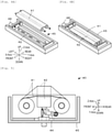
- Fig. 4 is an explanatory view illustrating an example of a configuration of cleaning unit 40, in which Fig. 4A is an exploded perspective view and Fig. 4B is a perspective view.
- Fig. 5 is a partial cross-sectional view of cleaning unit 40 as viewed from a side surface.
- Fig. 1 is a schematic explanatory view illustrating an example of mounting system 10 including printing device 11 which is an example of the present disclosure.
- Fig. 2 is an explanatory view illustrating a state where door member 16 is opened and cleaning unit 40 is pulled out to an outside.
- Fig. 3 is an explan
- FIG. 6 is an explanatory view of coupling section 50 in a coupling state.
- Fig. 7 is an explanatory view of coupling section 50 in a fixed state.
- Fig. 8 is a block diagram illustrating an electrical connection relationship of printing device 11.
- Mounting system 10 is, for example, a system for mounting a component on substrate S.
- Mounting system 10 includes printing device 11, mounting device 12, and management computer (PC) 90.
- Mounting system 10 is configured as a mounting line in which multiple mounting devices 12 that mount components on substrate S are disposed on a downstream side of printing device 11.
- a left-right direction (X-axis), a front-rear direction (Y-axis), and an up-down direction (Z-axis) are as illustrated in Figs. 1 , 4 , 5 , 10 , 12, and 13 .
- Mounting device 12 is a device that mounts a component on substrate S, on which a viscous fluid such as solder paste is printed by printing device 11.
- Management PC 90 is a device for managing information of each device of mounting system 10. Management PC 90 manages a progress state of each device on the mounting line. Each device of mounting system 10 exchanges information with management PC 90 to obtain information such as progress states of other devices.
- Printing device 11 is a device for applying (printing) solder as a viscous fluid to substrate S which is a printing target below via a pattern hole formed in the screen mask M by pushing the solder on screen mask M into a pattern hole formed in screen mask M using squeegee 27.
- the "printing target” include substrate S, on which a component is mounted, a three-dimensional object, or the like.
- Examples of the "viscous fluid” include solder paste, conductive paste, and adhesive.
- Printing device 11 includes control section 20 (refer to Fig. 8 ), printing section 24, mask section 28, substrate processing section 30, supply section 32, imaging section 35, and cleaning unit 40 serving as a cleaning section.
- Control section 20 is configured as a microprocessor mainly including CPU 21, and controls entire printing device 11. Although described in detail later, control section 20 unlocks door member 16 in a state where moving section 37 and cleaning unit 40 are disconnected and when cleaning unit 40 is located in a standby area. In addition, control section 20 executes a cleaning process after restricting a movement of slide mechanism 46 by lock mechanism 47 in a state where moving section 37 and cleaning unit 40 are connected to each other.
- a door member 16 that opens and closes opening portion 15 and is lockable in a closed state is disposed in main body 14 of printing device 11. Opening portion 15 is an area through which cleaning member 41 passes when cleaning member 41 is moved to an outside of printing device 11 when cleaning unit 40 is in the standby area (refer to Fig. 10 ).
- Door member 16 is a cleaning member exchange dedicated door member which is opened only when cleaning member 41 is exchanged.
- Door member 16 is disposed on a front surface of main body 14 of the printing device so as to open and close opening portion 15 provided on an extension line in a movement direction (front-rear direction) of cleaning unit 40.
- Door member 16 is pivotably disposed on main body 14 so as to close opening portion 15 in a vertical state and to open opening portion 15 in a horizontal state.
- closing mechanism 17 and closure sensor 18 are disposed in printing device 11.
- Closing mechanism 17 is a mechanism for causing door member 16 to be in a closed state by inserting lock pin 17a disposed on main body 14 into a hole portion disposed on door member 16, and includes a solenoid for driving lock pin 17a.
- a position sensor (not illustrated) is disposed in closing mechanism 17, and thus, a position of lock pin 17a can be detected.
- Closure sensor 18 is a sensor capable of outputting a signal when a sensor member disposed in door member 16 and a detection member disposed on the side of main body 14 are in proximity to each other, and detecting that door member 16 is closed by the output signal.
- Printing section 24 is disposed in an upper stage of printing device 11, and is a unit that perform printing process of the viscous fluid on substrate S using screen mask M.
- Printing section 24 includes printing head 25, print moving section 26, a squeegee raising/lowering section, and squeegee 27.
- Print moving section 26 moves printing head 25 in a predetermined printing direction (here, the front-rear direction), and includes a slider that moves along a guide formed in the front-rear direction and a motor that drives the slider.
- Squeegee 27 is disposed on a lower surface side of printing head 25 and is lifted or lowered by a squeegee raising/lowering section.
- Printing section 24 has two squeegees 27 used in the front-rear direction.
- Mask section 28 is disposed between printing section 24 and substrate processing section 30 in the up-down direction, and is a unit that fixedly holds screen mask M.
- Mask section 28 includes mask fixing section 29.
- Mask fixing section 29 positions screen mask M and supports and fixes screen mask M in a horizontal posture.
- Imaging section 35 includes camera 36, moving section 37, and engagement member 38 (refer to Fig. 8 ).
- Camera 36 captures images of substrate S and screen mask M.
- Imaging section 35 captures an image of a reference mark formed on substrate S or screen mask M.
- Control section 20 performs, for example, position alignment between screen mask M and substrate S based on the captured image.
- Moving section 37 moves imaging section 35 in a printing direction (the front-rear direction of the device), and includes a slider that moves along a guide formed in the front-rear direction and a motor that drives the slider.
- Engagement member 38 is a member coupled to cleaning unit 40 by coupling section 50 provided in cleaning unit 40 (refer to Figs. 6 and 7 ).
- Imaging section 35 can be connected to and disconnected from cleaning unit 40, and moving section 37 moves cleaning unit 40 together with camera 36.
- cleaning unit 40 does not have a moving section such as a motor, cleaning unit 40 is coupled to imaging section 35 by coupling section 50, and is moved in the front-rear direction between the cleaning area and the standby area by moving section 37 (refer to Fig. 10 ).
- Substrate processing section 30 is a unit that is disposed below mask section 28, conveys in substrate S, positions and supports carried-in substrate S, and brings substrate S into contact with screen mask M or separates substrate S from screen mask M.
- Substrate processing section 30 includes substrate conveyance section 31 that conveys substrate S in the left-right direction, a substrate supporting member that supports substrate S from below, and support raising/lowering section that lifts or lowers entire substrate processing section 30 and the substrate supporting member.
- Supply section 32 is a unit that supplies solder accommodated in cartridge 33 onto screen mask M.
- Supply section 32 is disposed in front of printing head 25.
- Supply section 32 applies a pressure to cartridge 33 to discharge the solder from cartridge 33.
- Cleaning unit 40 is disposed between mask section 28 and substrate processing section 30 in the up-down direction, and is a unit for performing a cleaning process for cleaning a rear surface of screen mask M.
- Cleaning unit 40 includes cleaning member 41, cleaning head 42, remaining amount detection sensor 44, attachment section 45, slide mechanism 46, lock mechanism 47, take-up motor 48, and coupling section 50.
- Cleaning member 41 wipes off an adhered matter adhering to screen mask M, and may be, for example, cleaning paper or the like.
- cleaning head 42 is a member for cleaning screen mask M by contacting cleaning member 41 for cleaning screen mask M with screen mask M.
- Cleaning head 42 is a rod-like member having a rectangular parallelepiped shape of which a longitudinal direction is an X-axis direction (left-right direction). Cleaning head 42 is lifted and lowered between a cleaning position (refer to dashed lines in Fig. 5 ) and a standby position (refer to solid lines in Fig. 5 ) by a lifting and lowering mechanism (not illustrated) to clean screen mask M at the cleaning position.
- remaining amount detection sensor 44 is a sensor that contacts cleaning member 41 and detects a remaining amount (used amount) of cleaning member 41 by rotating in accordance with the winding of cleaning member 41. Control section 20 can predict an exchange time of cleaning member 41 based on a signal from remaining amount detection sensor 44.
- Attachment section 45 is a member that rotatably supports cleaning member 41, and attaches cleaning member 41.
- Attachment section 45 is a box-shaped member having an open upper surface that supports a first shaft and a second shaft over which cleaning member 41 is bridged.
- Slide mechanism 46 is a mechanism for sliding attachment section 45 to pull attachment section 45 to the outside of printing device 11 (refer to Fig. 2 ).
- Slide mechanism 46 is fixed to a left surface and a right surface of attachment section 45 as well as to a housing side of cleaning unit 40, and slides and supports attachment section 45 in the front-rear direction.
- Lock mechanism 47 is a mechanism for restricting a movement of slide mechanism 46, and includes a restricting pin and a solenoid for driving the restricting pin.
- Lock mechanism 47 is fixed to the housing side of cleaning unit 40, and restricts the movement of slide mechanism 46 by inserting the restricting pin into a hole portion formed in attachment section 45 to fix attachment section 45 (refer to Fig. 1 ). Lock mechanism 47 is driven by control section 20.
- Take-up motor 48 is a motor for rotationally driving a first shaft for winding used cleaning member 41.
- Coupling section 50 connects and disconnects cleaning unit 40 and imaging section 35 (moving section 37). Moreover, coupling section 50 serves as a fixing section for fixing cleaning unit 40 to main body 14. That is, coupling section 50 fixes cleaning unit 40 to main body 14 of printing device in the standby area and releases the connection with moving section 37, while connecting cleaning unit 40 and moving section 37 and releasing fixing to main body 14. Coupling section 50 is disposed at a left end portion and a right end portion of cleaning unit 40. As illustrated in Figs. 6 and 7 , coupling section 50 includes fixing rod 51 and air cylinder 52 (driving section). Fixing rod 51 is a rod-like member inserted into air cylinder 52, and is driven by air cylinder 52.
- Fixing rod 51 moves between a moving section coupling position ( Fig. 6 ) for connecting cleaning unit 40 and moving section 37 and releasing the fixing to main body 14, and a main body fixing position ( Fig. 7 ) for fixing cleaning unit 40 to main body 14 and releasing the connection to moving section 37.
- Engagement member 38 having an L-shaped insertion hole formed in a horizontal plane is fixed to imaging section 35.
- L-shaped fixing member 19 having an insertion hole formed in a horizontal plane in a column member is fixed to main body 14.
- Fixing rod 51 is inserted only into engagement member 38 in the moving section coupling position, and is inserted only into fixing member 19 in the main body fixing position.
- Pressurized air (not illustrated) is supplied to air cylinder 52, and thus, fixing rod 51 is driven up and down by switching of a supply path.
- fixed detection sensor 53 is disposed on fixing member 19.
- Fixed detection sensor 53 is a sensor that outputs a signal when a plate-like member disposed in cleaning unit 40 is inserted.
- Control section 20 can detect that cleaning unit 40 is present in the standby area based on the output signal of fixed detection sensor 53.
- a coupling sensor (not illustrated) is disposed in imaging section 35, and thus, it is possible to confirm whether cleaning unit 40 is appropriately coupled.
- a position sensor (not illustrated) is disposed in coupling section 50, and thus, a position of fixing rod 51 can be detected.
- FIG. 9 is a flowchart illustrating an example of a printing process routine executed by CPU 21 of control section 20.
- This routine is stored in a storage section of control section 20 and executed in accordance with an input of the operator to initiate the print process.
- CPU 21 causes substrate processing section 30 to convey and fix substrate S (S100), causes imaging section 35 to read reference marks of substrate S and screen mask M, to perform the position alignment between substrate S and screen mask M (S110), and causes printing section 24 to execute the print process (S120).
- printing head 25 is moved, and the solder paste is supplied onto substrate S disposed on a lower surface of screen mask M by squeegee 27.
- CPU 21 determines whether it is a supply timing for the solder (S130), and when it is the supply timing for the solder, CPU 21 causes supply section 32 to supply the solder on screen mask M (S140).
- the determination of the supply timing for the solder may be made by detecting an amount of solder used or by predicting the amount of solder based on a printing time.
- CPU 21 determines whether it is a cleaning timing for screen mask M (S150). This determination can be made based on whether the print process time has elapsed a predetermined cleaning time. When it is the cleaning timing for screen mask M, CPU 21 couples moving section 37 to cleaning unit 40 (S160), and executes the cleaning process of screen mask M by cleaning unit 40 (S170).
- Fig. 10 is an explanatory view of the cleaning process of screen mask M by cleaning unit 40.
- CPU 21 moves imaging section 35 to the vicinity of cleaning unit 40 waiting in the standby area, moves fixing rod 51 of coupling section 50 to the moving section coupling position, couples moving section 37 and cleaning unit 40, and releases the fixing to main body 14.
- CPU 21 moves cleaning unit 40 to a lower surface of screen mask M, lifts cleaning head 42 to the cleaning position, and causes cleaning member 41 to clean the lower surface of screen mask M ( Fig. 10). (Fig. 10 )
- CPU 21 causes moving section 37 to move cleaning unit 40 to the standby area, moves fixing rod 51 to the main body fixing position, releases the coupling of coupling section 50, and fixes cleaning unit 40 (S180).
- CPU 21 determines whether a production process of substrate S is completed (S190), and executes processes after S100 when the production process of substrate S is not completed. Meanwhile, when the production process of substrate S is completed in S190, the routine is finished.
- FIG. 11 is a flowchart illustrating an example of a cleaning member exchange process routine executed by CPU 21 of control section 20.
- This routine is stored in the storage section of control section 20, and is repeatedly executed at predetermined intervals in parallel with the printing process routine.
- CPU 21 determines whether it is an exchange timing for cleaning member 41 based on a remaining amount of cleaning member 41 detected by remaining amount detection sensor 44 (S200). If it is not the exchange timing for cleaning member 41, CPU 21 terminates this routine as it is. Meanwhile, when it is exchange timing for cleaning member 41 in S200, CPU 21 determines whether cleaning unit 40 is in the standby area and the coupling with moving section 37 is released (S210).
- Fig. 12 is an explanatory view of the decoupling and main body fixing process of coupling section 50.
- CPU 21 drives lock pin 17a of closing mechanism 17 to release the closed state of door member 16 (S230), and drives the restricting pin of lock mechanism 47 to release the locking of the movement restriction of slide mechanism 46 (S240).
- CPU 21 causes a display section of an operation panel to display an instruction to exchange cleaning member 41.
- the operator confirms a display content of the display section, opens door member 16, holds a handle fixed to a front surface of attachment section 45, and moves attachment section 45 to the outside of the device by slide mechanism 46.
- Fig. 13 is an explanatory view illustrating a state where cleaning member 41 is changed by pulling out attachment section 45. The operator removes used cleaning member 41 (refer to Fig. 4A ), attaches new cleaning member 41 (refer to Fig. 4B ), moves attachment section 45 into the device, and closes door member 16.
- CPU 21 determines whether an exchange completion input inputted by the operator is acquired from the operation panel (S260), and waits as it is when the exchange completion is not inputted. Meanwhile, when the exchange completion is inputted in S260, the remaining amount of cleaning member 41 is updated (S270), and the routine is finished.
- the printing process routine and the cleaning member exchange process routine can be executed in parallel, and thus, the cleaning member 41 can be exchanged without stopping the print process at all.
- Screen mask M of the present embodiment corresponds to a screen mask
- substrate S corresponds to a printing target
- the solder paste corresponds to a viscous fluid
- cleaning member 41 corresponds to a cleaning member
- cleaning head 42 corresponds to a cleaning head
- moving section 37 corresponds to a moving section
- opening portion 15 corresponds to an opening portion
- closing mechanism 17 corresponds to a closing mechanism
- door member 16 corresponds to a door member
- control section 20 corresponds to a control section.
- main body 14 corresponds to a main body
- coupling section 50 corresponds to a coupling section
- fixing rod 51 corresponds to a fixing rod
- air cylinder 52 corresponds to a driving section
- attachment section 45 corresponds to an attachment section
- slide mechanism 46 corresponds to a slide mechanism
- lock mechanism 47 corresponds to a lock mechanism
- imaging section 35 corresponds to an imaging section
- printing section 24 corresponds to the printing section.
- a cleaning unit of the present disclosure and a control method for a printing device of the present disclosure are disclosed by descriptions of printing device 11.
- printing device 11 of the present embodiment described above in a state where moving section 37 and cleaning unit 40 are disconnected from each other and in a state where cleaning unit 40 is located in the standby area, door member 16 that opens and closes opening portion 15 in the vicinity of the standby area is unlocked.
- this printing device 11 when door member 16 is made openable, since cleaning unit 40 is in the standby area and closes opening portion 15, an operator is prevented from accessing inside of the device from opening portion 15, and thus, security can be secured.
- printing device 11 allows door member 16 to be opened, since cleaning unit 40 is disconnected from moving section 37, it is also prevented from moving from the standby area.
- cleaning unit 40 includes coupling section 50 that fixes cleaning unit 40 to main body 14 side in the standby area and releases the connection with moving section 37, while connecting cleaning unit 40 and moving section 37 and releasing the fixing to main body 14 side.
- the movement and the fixing of cleaning unit 40 can be switched by using coupling section 50.
- coupling section 50 includes fixing rod 51 that moves between the main body fixing position for fixing cleaning unit 40 to main body 14 side and releasing the connection to moving section 37 and the moving section coupling position for connecting cleaning unit 40 and moving section 37 and releasing the fixing to main body 14 side, and air cylinder 52 serving as the driving section for moving fixing rod 51 between the main body fixing position and the moving section coupling position.
- the movement and the fixing of cleaning unit 40 can be switched by a relatively simple structure.
- cleaning unit 40 includes attachment section 45 to which cleaning member 41 is attached, slide mechanism 46 that slides attachment section 45 to pull attachment section 45 to the outside of printing device 11, and lock mechanism 47 that restricts the movement of slide mechanism 46, and control section 20 releases the restriction of lock mechanism 47 in the state where moving section 37 and cleaning unit 40 are disconnected from each other and in the state where cleaning unit 40 is in the standby area.
- cleaning member 41 can be moved to the outside relatively easily by using slide mechanism 46 having a simpler configuration.
- the operation restriction of slide mechanism 46 is released in a state where cleaning member 41 is exchangeable, it is possible to prevent cleaning member 41 from being inadvertently pulled out to the outside.
- control section 20 executes the cleaning process after restricting the movement of slide mechanism 46 by lock mechanism 47 in a state where moving section 37 and cleaning unit 40 are connected to each other.
- security can be further secured by restricting the operation of slide mechanism 46 by lock mechanism 47 when cleaning unit 40 performs the cleaning process.
- door member 16 is disposed on main body 14 side of printing device 11 so as to open and close opening portion 15 provided on the extension line in the movement direction of cleaning unit 40.
- the movement direction is unified, and thus, cleaning member 41 can be easily moved to the outside.
- door member 16 is pivotably disposed on main body 14 side so as to close opening portion 15 in the vertical state and to open opening portion 15 in the horizontal state.
- cleaning member 41 is exchanged in a state where cleaning member 41 passes through opening portion 15 and is pulled out of the device, it is possible to realize compactness of the device.
- moving section 37 is imaging section 35 including camera 36 for capturing an image of at least one of the printing target and screen mask M.
- imaging section 35 including camera 36 for capturing an image of at least one of the printing target and screen mask M.
- printing device 11 further includes printing section 24 that performs the print process of the viscous fluid (solder paste) on the printing target (substrate S) using screen mask M. In printing device 11, the print process can be performed by printing section 24.
- the printing device, the cleaning unit, and the control method for the printing device of the present disclosure are not limited to any of the above embodiments, and may be implemented in various manners as long as they fall within a technical scope of the present disclosure.
- coupling section 50 has fixing rod 51 and air cylinder 52 that switch the coupling between cleaning unit 40 and moving section 37 and the fixing of cleaning unit 40 to main body 14; however, the configuration is not limited to this, and a member that couples cleaning unit 40 and moving section 37 and a member that fixes cleaning unit 40 to main body 14 side may be separate members. Although the number of members increases even in printing device, it is possible to further suppress the interruption of the process related to the printing while securing security when cleaning member 41 is exchanged.
- cleaning unit 40 includes attachment section 45, slide mechanism 46, and lock mechanism 47, and only attachment section 45 is pulled out of the device; however, the configuration is not limited to this.
- attachment section 45, slide mechanism 46, and lock mechanism 47 may be omitted, and thus, cleaning unit 40 itself may be pulled out of opening portion 15. Even in this printing device, it is possible to further suppress the interruption of the process while securing security when cleaning member 41 is exchanged.
- door member 16 is provided in opening portion 15 provided on the extension line in the movement direction (printing direction, front-rear direction) of cleaning unit 40, and cleaning member 41 is moved from opening portion 15 to the outside; however, the configuration is not limited to this.
- door member 16 may be disposed in an opening portion provided in a direction different from the movement direction of cleaning unit 40, and thus, cleaning member 41 may be moved to the outside from the opening portion.
- the direction in which cleaning member 41 is removed may be arbitrary, it is preferable that cleaning member 41 moves to the outside along the movement direction of cleaning unit 40.
- door member 16 is configured to close opening portion 15 in the vertical state and to open opening portion 15 in the horizontal state; however, an opening operation of door member 16 is not particularly limited to this and is arbitrary as long as door member 16 can be opened.
- door member 16 may be pivoted toward the front-down direction, or may be pivoted toward the front-up direction to open opening portion 15. It should be noted that in view of the exchange of cleaning member 41, it is preferable that door member 16 pivots toward the front-down direction.
- moving section 37 moves imaging section 35 and cleaning unit 40; however, the configuration is not limited to this, cleaning unit 40 may be moved by a moving section different from imaging section 35.
- the number of moving sections increases even in printing device, it is possible to further suppress the interruption of the process related to the printing while securing security when cleaning member 41 is exchanged.
- door member 16 is locked by closing mechanism 17 including lock pin 17a and solenoid; however, the configuration is not limited to this as long as door member 16 can be locked in the closed state.
- closing mechanism 17 including lock pin 17a and solenoid; however, the configuration is not limited to this.
- lock mechanism 47 includes the restricting pin and the solenoid for driving the restricting pin, and is inserted into the attachment section 45; however, the configuration is not limited to this as long as lock mechanism 47 restricts the movement of slide mechanism 46.
- Lock mechanism 47 may restrict the slide itself of slide mechanism 46. As such a mechanism, a mechanism having known shape and action can be appropriately used.
- door member 16 is disposed on the main body side, and fixing rod 51 is inserted into fixing member 19 disposed on main body 14, that is, door member 16 and fixing rod 51 are fixed to the main body side; however, examples of the member on the main body side include a housing, a fixing member, a cover member, and a column member disposed in the main body as long as it is not a member that frequently moves or operates as in cleaning unit 40.
- the present disclosure has been described as printing device 11 including cleaning unit 40; however, the present disclosure is not limited to this, and may be only cleaning unit 40 or may be the control method for printing device 11.
- the cleaning section may include a coupling section configured to fix the cleaning section to a main body side of the printing device in the standby area and release connection with the moving section, while connecting the cleaning section and the moving section and releasing the fixing to the main body side of the printing device.
- the movement and the fixing of the cleaning section can be switched by using the coupling section.
- the coupling section may include a fixing rod that moves between a main body fixing position for fixing the cleaning section to the main body side and releasing the connection to the moving section and the moving section coupling position for connecting the cleaning section and the moving section and releasing the fixing to main body side, and a driving section for moving the fixing rod between the main body fixing position and the moving section coupling position.
- the movement and the fixing of the cleaning section can be switched by a relatively simple structure.
- the cleaning section may include an attachment section configured to attach the cleaning member, a slide mechanism configured to slide the attachment section to pull the attachment section to the outside of the printing device, and a lock mechanism configured to restrict a movement of the slide mechanism, and the control section may release the restriction of the lock mechanism in a state where the moving section and the cleaning section are disconnected from each other and in a state where the cleaning section is located in the standby area.
- the cleaning member can be moved to the outside relatively easily using the slide mechanism having a simpler configuration.
- since the operation restriction of the slide mechanism is released in a state where the cleaning member is exchangeable, it is possible to prevent the cleaning member from being inadvertently pulled out to the outside.
- control section may execute the cleaning process after restricting the movement of the slide mechanism by the lock mechanism in a state where the moving section and the cleaning section are connected to each other.
- security can be further secured by restricting the operation of the slide mechanism by the lock mechanism when the cleaning section performs the cleaning process.
- the door member may be disposed on the main body side of the printing device so as to open and close an opening portion provided on an extension line in a movement direction of the cleaning section.
- the movement direction is unified, and thus, the cleaning member can be easily moved to the outside.
- the door member may be pivotably disposed on the main body side so as to close the opening portion in a vertical state and to open the opening portion in a horizontal state.
- the cleaning member is exchanged in a state where the cleaning member passes through the opening portion and is pulled out of the device, it is possible to realize compactness of the device.
- main body side does not mean a member that frequently moves or operates such as a cleaning section, but includes a housing that is a main body, a fixing member, a cover member, a column member, and the like disposed in the main body.
- the moving section may include an imaging section configured to capture an image of the printing target and/or the screen mask.
- the moving section since the moving section moves both the imaging section and the cleaning section, the device configuration can be further simplified.
- the printing device of the present disclosure may include a printing section configured to perform the print process of the viscous fluid on the printing target using the screen mask.
- the print process can be performed by a printing section.
- a cleaning unit used in a printing device for performing a print process of a viscous fluid on a printing target using a screen mask the cleaning unit including a cleaning head configured to contact a cleaning member with the screen mask to perform a cleaning process on the screen mask, and a control section configured to unlock a door member configured to open and close an opening portion through which the cleaning member passes when the cleaning member is moved from a standby area to an outside of the printing device and be lockable in a closed state in a state where a moving section connectable and disconnectable to the cleaning unit and moving the cleaning unit between a cleaning area and the standby area and the cleaning unit are disconnected to each other and in a state where the cleaning unit is located in the standby area.
- the cleaning unit has the same configuration as that of the printing device, similarly to the printing device, it is possible to further suppress the interruption of the processing while securing security when exchanging the cleaning member used in the printing device. It should be noted that various modes of the above-described printing device may be employed in the cleaning unit, and a configuration for realizing each function of the above-described printing device may be added.
- a control method for a printing device for performing a print process of a viscous fluid on a printing target using a screen mask including a cleaning section configured to contact a cleaning member with the screen mask to perform a cleaning process on the screen mask, a moving section connectable and disconnectable to the cleaning section to move the cleaning section between a cleaning area and a standby area, and a door member configured to open and close an opening portion through which the cleaning member passes when the cleaning member is moved from the standby area to an outside of the printing device and be lockable in a closed state
- the control method including unlocking the door member in a state where the moving section and the cleaning section are disconnected from each other and the cleaning section is located in the standby area.
- control method for the printing device since the same process as that of the printing device is performed, similarly to the printing device, it is possible to further suppress the interruption of the process while securing security when exchanging the cleaning member used in the printing device. It should be noted that various modes of the above-described printing device may be employed in the control method for the printing device, and a step for realizing each function of the above-described printing device may be added.
- the present disclosure can be used in a technical field of a device for printing a viscous fluid on a printing target.
Landscapes
- Engineering & Computer Science (AREA)
- Mechanical Engineering (AREA)
- Screen Printers (AREA)
- Electric Connection Of Electric Components To Printed Circuits (AREA)
- Inking, Control Or Cleaning Of Printing Machines (AREA)
- Manufacturing Of Printed Wiring (AREA)
Abstract
Description
- The present specification discloses a printing device, a cleaning unit, and a control method for a printing device.
- Conventionally, in a printing device for performing a print process of a viscous fluid on a printing target such as a substrate using a screen mask, there has been proposed a device including a cleaning unit that contacts and cleans a rear surface of a screen mask (refer to Patent Literature 1, for example). In this printing device, when the cleaning unit is located in the replenishment area where a cleaning paper (cleaning member) is replenished, the cleaning member can be replenished, and thus, screen printing can be continued even during a replenishment work of the cleaning member.
- Patent Literature 1:
JP-A-2015-80870 - However, in the above-described printing device, since an opening/closing cover is provided in the replenishment area, when the cleaning unit is not present in the replenishment area and the opening/closing cover is opened, a process related to the printing is stopped in consideration of security. As described above, in the printing device described in Patent Literature 1, the process related to printing may be interrupted.
- The present disclosure has been made in view of such problems, and a main object of the present disclosure is to provide a printing device, a cleaning unit, and a control method for a printing device capable of further suppressing interruption of a process while securing security when exchanging a cleaning member used in the printing device.
- A printing device, a cleaning unit, and a control method for the printing device disclosed in the present specification employs the following means in order to achieve the main object described above.
- According to an aspect of the present disclosure, there is provided a printing device for performing a print process of a viscous fluid on a printing target using a screen mask, the printing device including: a cleaning section having a cleaning head configured to contact a cleaning member with the screen mask to perform a cleaning process on the screen mask; a moving section connectable and disconnectable to the cleaning section to move the cleaning section between a cleaning area and a standby area; a door member configured to open and close an opening portion through which the cleaning member passes when the cleaning member is moved from the standby area to an outside of the printing device and be lockable in a closed state; and a control section configured to unlock the door member in a state where the moving section and the cleaning section are disconnected from each other and in a state where the cleaning section is located in the standby area.
- In this printing device, in the state where the moving section and the cleaning section are disconnected from each other and in the state where the cleaning section is located in the standby area, the door member that opens and closes the opening portion in the vicinity of the standby area is unlocked. In this printing device, when the door member is made openable, since the cleaning section is in the standby area and closes the opening portion, an operator is prevented from accessing inside of the device from the opening portion, and thus, security can be secured. In addition, when the printing device allows the door member to be opened, since the cleaning section is disconnected from the moving section, the cleaning section is also prevented from moving from the standby area. It should be noted that although the door member is locked in the closed state when the cleaning section is not in the standby area, there is no reason to open the door member, and thus, usability is not obstructed. Then, the operator can expose the cleaning member to the outside through the opening portion opened by the door member to exchange the cleaning member. Accordingly, in this printing device, when exchanging the cleaning member used in the printing device, it is possible to further suppress interruption of a process while securing security. Herein, examples of the "printing target" include a substrate on which a component is mounted, a three-dimensional object, or the like. In addition, examples of the "viscous fluid" include solder paste, conductive paste, and adhesive. In addition, an example of the cleaning member includes cleaning paper. Moreover, the expression "suppressing the interruption of the process" means suppressing the interruption of the process related to printing, and includes, for example, convey-in and convey-out processes of the printing target, a supply process of the viscous fluid, positioning processing between the screen mask and the printing target, or the like in addition to the print process itself.
-
-
Fig. 1 is a schematic explanatory view illustrating an example ofmounting system 10. -
Fig. 2 is an explanatory view illustrating a state wheredoor member 16 is opened and cleaningunit 40 is pulled out to an outside. -
Fig. 3 is an explanatory view ofclosing mechanism 17 andclosure sensor 18 as viewed from an inside ofmain body 14. -
Fig. 4 is an explanatory view illustrating an example of a configuration ofcleaning unit 40. -
Fig. 5 is a partial cross-sectional view ofcleaning unit 40 as viewed from a side surface. -
Fig. 6 is an explanatory view ofcoupling section 50 in a coupling state. -
Fig. 7 is an explanatory view ofcoupling section 50 in a fixed state. -
Fig. 8 is a block diagram illustrating an electrical connection relationship ofprinting device 11. -
Fig. 9 is a flowchart illustrating an example of a printing process routine. -
Fig. 10 is an explanatory view of a cleaning process. -
Fig. 11 is a flowchart illustrating an example of a cleaning member exchange process routine. -
Fig. 12 is an explanatory view of decoupling and main body fixing processes ofcoupling section 50. -
Fig. 13 is an explanatory view illustrating a state wherecleaning member 41 is changed by pulling outattachment section 45. - The present embodiment will be described below with reference to the drawings.
Fig. 1 is a schematic explanatory view illustrating an example ofmounting system 10 includingprinting device 11 which is an example of the present disclosure.Fig. 2 is an explanatory view illustrating a state wheredoor member 16 is opened and cleaningunit 40 is pulled out to an outside.Fig. 3 is an explanatory view ofclosing mechanism 17 andclosure sensor 18 as viewed from an inside ofmain body 14.Fig. 4 is an explanatory view illustrating an example of a configuration ofcleaning unit 40, in whichFig. 4A is an exploded perspective view andFig. 4B is a perspective view.Fig. 5 is a partial cross-sectional view ofcleaning unit 40 as viewed from a side surface.Fig. 6 is an explanatory view ofcoupling section 50 in a coupling state.Fig. 7 is an explanatory view ofcoupling section 50 in a fixed state.Fig. 8 is a block diagram illustrating an electrical connection relationship ofprinting device 11.Mounting system 10 is, for example, a system for mounting a component on substrateS. Mounting system 10 includesprinting device 11,mounting device 12, and management computer (PC) 90.Mounting system 10 is configured as a mounting line in whichmultiple mounting devices 12 that mount components on substrate S are disposed on a downstream side ofprinting device 11. In the present embodiment, a left-right direction (X-axis), a front-rear direction (Y-axis), and an up-down direction (Z-axis) are as illustrated inFigs. 1 ,4 ,5 ,10 ,12, and 13 . -
Mounting device 12 is a device that mounts a component on substrate S, on which a viscous fluid such as solder paste is printed byprinting device 11. Management PC 90 is a device for managing information of each device ofmounting system 10. Management PC 90 manages a progress state of each device on the mounting line. Each device ofmounting system 10 exchanges information with management PC 90 to obtain information such as progress states of other devices. -
Printing device 11 is a device for applying (printing) solder as a viscous fluid to substrate S which is a printing target below via a pattern hole formed in the screen mask M by pushing the solder on screen mask M into a pattern hole formed in screen maskM using squeegee 27. Examples of the "printing target" include substrate S, on which a component is mounted, a three-dimensional object, or the like. Examples of the "viscous fluid" include solder paste, conductive paste, and adhesive. Herein, substrate S and solder will be described below as examples.Printing device 11 includes control section 20 (refer toFig. 8 ),printing section 24,mask section 28,substrate processing section 30,supply section 32,imaging section 35, andcleaning unit 40 serving as a cleaning section.Control section 20 is configured as a microprocessor mainly includingCPU 21, and controlsentire printing device 11. Although described in detail later,control section 20 unlocksdoor member 16 in a state where movingsection 37 andcleaning unit 40 are disconnected and whencleaning unit 40 is located in a standby area. In addition,control section 20 executes a cleaning process after restricting a movement ofslide mechanism 46 bylock mechanism 47 in a state where movingsection 37 andcleaning unit 40 are connected to each other. - As illustrated in
Fig. 2 , adoor member 16 that opens and closes openingportion 15 and is lockable in a closed state is disposed inmain body 14 ofprinting device 11. Openingportion 15 is an area through which cleaningmember 41 passes when cleaningmember 41 is moved to an outside ofprinting device 11 when cleaningunit 40 is in the standby area (refer toFig. 10 ).Door member 16 is a cleaning member exchange dedicated door member which is opened only when cleaningmember 41 is exchanged.Door member 16 is disposed on a front surface ofmain body 14 of the printing device so as to open andclose opening portion 15 provided on an extension line in a movement direction (front-rear direction) ofcleaning unit 40.Door member 16 is pivotably disposed onmain body 14 so as to close openingportion 15 in a vertical state and to open openingportion 15 in a horizontal state. As illustrated inFig. 3 ,closing mechanism 17 andclosure sensor 18 are disposed inprinting device 11.Closing mechanism 17 is a mechanism for causingdoor member 16 to be in a closed state by insertinglock pin 17a disposed onmain body 14 into a hole portion disposed ondoor member 16, and includes a solenoid for drivinglock pin 17a. In addition, a position sensor (not illustrated) is disposed inclosing mechanism 17, and thus, a position oflock pin 17a can be detected.Closure sensor 18 is a sensor capable of outputting a signal when a sensor member disposed indoor member 16 and a detection member disposed on the side ofmain body 14 are in proximity to each other, and detecting thatdoor member 16 is closed by the output signal. -
Printing section 24 is disposed in an upper stage ofprinting device 11, and is a unit that perform printing process of the viscous fluid on substrate S using screen maskM. Printing section 24 includesprinting head 25,print moving section 26, a squeegee raising/lowering section, andsqueegee 27.Print moving section 26moves printing head 25 in a predetermined printing direction (here, the front-rear direction), and includes a slider that moves along a guide formed in the front-rear direction and a motor that drives the slider.Squeegee 27 is disposed on a lower surface side ofprinting head 25 and is lifted or lowered by a squeegee raising/lowering section.Printing section 24 has twosqueegees 27 used in the front-rear direction.Mask section 28 is disposed betweenprinting section 24 andsubstrate processing section 30 in the up-down direction, and is a unit that fixedly holds screen maskM. Mask section 28 includesmask fixing section 29. Mask fixingsection 29 positions screen mask M and supports and fixes screen mask M in a horizontal posture. -
Imaging section 35 includescamera 36, movingsection 37, and engagement member 38 (refer toFig. 8 ).Camera 36 captures images of substrate S and screen maskM. Imaging section 35 captures an image of a reference mark formed on substrate S or screen maskM. Control section 20 performs, for example, position alignment between screen mask M and substrate S based on the captured image. Movingsection 37moves imaging section 35 in a printing direction (the front-rear direction of the device), and includes a slider that moves along a guide formed in the front-rear direction and a motor that drives the slider.Engagement member 38 is a member coupled to cleaningunit 40 bycoupling section 50 provided in cleaning unit 40 (refer toFigs. 6 and 7 ).Imaging section 35 can be connected to and disconnected from cleaningunit 40, and movingsection 37moves cleaning unit 40 together withcamera 36. Although cleaningunit 40 does not have a moving section such as a motor, cleaningunit 40 is coupled toimaging section 35 bycoupling section 50, and is moved in the front-rear direction between the cleaning area and the standby area by moving section 37 (refer toFig. 10 ). -
Substrate processing section 30 is a unit that is disposed belowmask section 28, conveys in substrate S, positions and supports carried-in substrate S, and brings substrate S into contact with screen mask M or separates substrate S from screen mask M.Substrate processing section 30 includessubstrate conveyance section 31 that conveys substrate S in the left-right direction, a substrate supporting member that supports substrate S from below, and support raising/lowering section that lifts or lowers entiresubstrate processing section 30 and the substrate supporting member.Supply section 32 is a unit that supplies solder accommodated incartridge 33 onto screen maskM. Supply section 32 is disposed in front ofprinting head 25.Supply section 32 applies a pressure tocartridge 33 to discharge the solder fromcartridge 33. -
Cleaning unit 40 is disposed betweenmask section 28 andsubstrate processing section 30 in the up-down direction, and is a unit for performing a cleaning process for cleaning a rear surface of screen maskM. Cleaning unit 40 includes cleaningmember 41, cleaninghead 42, remainingamount detection sensor 44,attachment section 45,slide mechanism 46,lock mechanism 47, take-upmotor 48, andcoupling section 50.Cleaning member 41 wipes off an adhered matter adhering to screen mask M, and may be, for example, cleaning paper or the like. As illustrated inFigs. 4 and 5 , cleaninghead 42 is a member for cleaning screen mask M by contacting cleaningmember 41 for cleaning screen mask M with screen maskM. Cleaning head 42 is a rod-like member having a rectangular parallelepiped shape of which a longitudinal direction is an X-axis direction (left-right direction).Cleaning head 42 is lifted and lowered between a cleaning position (refer to dashed lines inFig. 5 ) and a standby position (refer to solid lines inFig. 5 ) by a lifting and lowering mechanism (not illustrated) to clean screen mask M at the cleaning position. As illustrated inFig. 5 , remainingamount detection sensor 44 is a sensor thatcontacts cleaning member 41 and detects a remaining amount (used amount) of cleaningmember 41 by rotating in accordance with the winding of cleaningmember 41.Control section 20 can predict an exchange time of cleaningmember 41 based on a signal from remainingamount detection sensor 44. -
Attachment section 45 is a member that rotatably supports cleaningmember 41, and attaches cleaningmember 41.Attachment section 45 is a box-shaped member having an open upper surface that supports a first shaft and a second shaft over which cleaningmember 41 is bridged.Slide mechanism 46 is a mechanism for slidingattachment section 45 to pullattachment section 45 to the outside of printing device 11 (refer toFig. 2 ).Slide mechanism 46 is fixed to a left surface and a right surface ofattachment section 45 as well as to a housing side of cleaningunit 40, and slides and supportsattachment section 45 in the front-rear direction.Lock mechanism 47 is a mechanism for restricting a movement ofslide mechanism 46, and includes a restricting pin and a solenoid for driving the restricting pin.Lock mechanism 47 is fixed to the housing side of cleaningunit 40, and restricts the movement ofslide mechanism 46 by inserting the restricting pin into a hole portion formed inattachment section 45 to fix attachment section 45 (refer toFig. 1 ).Lock mechanism 47 is driven bycontrol section 20. Take-upmotor 48 is a motor for rotationally driving a first shaft for winding used cleaningmember 41. - Coupling
section 50 connects and disconnects cleaningunit 40 and imaging section 35 (moving section 37). Moreover,coupling section 50 serves as a fixing section for fixingcleaning unit 40 tomain body 14. That is, couplingsection 50fixes cleaning unit 40 tomain body 14 of printing device in the standby area and releases the connection with movingsection 37, while connectingcleaning unit 40 and movingsection 37 and releasing fixing tomain body 14. Couplingsection 50 is disposed at a left end portion and a right end portion of cleaningunit 40. As illustrated inFigs. 6 and 7 ,coupling section 50 includes fixingrod 51 and air cylinder 52 (driving section). Fixingrod 51 is a rod-like member inserted intoair cylinder 52, and is driven byair cylinder 52. Fixingrod 51 moves between a moving section coupling position (Fig. 6 ) for connectingcleaning unit 40 and movingsection 37 and releasing the fixing tomain body 14, and a main body fixing position (Fig. 7 ) for fixingcleaning unit 40 tomain body 14 and releasing the connection to movingsection 37.Engagement member 38 having an L-shaped insertion hole formed in a horizontal plane is fixed toimaging section 35. In addition, L-shaped fixingmember 19 having an insertion hole formed in a horizontal plane in a column member is fixed tomain body 14. Fixingrod 51 is inserted only intoengagement member 38 in the moving section coupling position, and is inserted only into fixingmember 19 in the main body fixing position. Pressurized air (not illustrated) is supplied toair cylinder 52, and thus, fixingrod 51 is driven up and down by switching of a supply path. In addition, fixeddetection sensor 53 is disposed on fixingmember 19.Fixed detection sensor 53 is a sensor that outputs a signal when a plate-like member disposed in cleaningunit 40 is inserted.Control section 20 can detect that cleaningunit 40 is present in the standby area based on the output signal of fixeddetection sensor 53. In addition, a coupling sensor (not illustrated) is disposed inimaging section 35, and thus, it is possible to confirm whether cleaningunit 40 is appropriately coupled. In addition, a position sensor (not illustrated) is disposed incoupling section 50, and thus, a position of fixingrod 51 can be detected. - Next, an operation of
printing device 11 configured as described above, first, an operation of the print process will be described.Fig. 9 is a flowchart illustrating an example of a printing process routine executed byCPU 21 ofcontrol section 20. This routine is stored in a storage section ofcontrol section 20 and executed in accordance with an input of the operator to initiate the print process. When this routine is executed,CPU 21 causessubstrate processing section 30 to convey and fix substrate S (S100), causesimaging section 35 to read reference marks of substrate S and screen mask M, to perform the position alignment between substrate S and screen mask M (S110), and causesprinting section 24 to execute the print process (S120). In print process,printing head 25 is moved, and the solder paste is supplied onto substrate S disposed on a lower surface of screen mask M bysqueegee 27. Next,CPU 21 determines whether it is a supply timing for the solder (S130), and when it is the supply timing for the solder,CPU 21causes supply section 32 to supply the solder on screen mask M (S140). The determination of the supply timing for the solder may be made by detecting an amount of solder used or by predicting the amount of solder based on a printing time. - After S140 or when it is not the supply timing for the solder in S130,
CPU 21 determines whether it is a cleaning timing for screen mask M (S150). This determination can be made based on whether the print process time has elapsed a predetermined cleaning time. When it is the cleaning timing for screen mask M,CPU 21couples moving section 37 to cleaning unit 40 (S160), and executes the cleaning process of screen mask M by cleaning unit 40 (S170).Fig. 10 is an explanatory view of the cleaning process of screen mask M by cleaningunit 40. In S160,CPU 21moves imaging section 35 to the vicinity of cleaningunit 40 waiting in the standby area, moves fixingrod 51 ofcoupling section 50 to the moving section coupling position, couples movingsection 37 andcleaning unit 40, and releases the fixing tomain body 14. In S170,CPU 21moves cleaning unit 40 to a lower surface of screen mask M, lifts cleaninghead 42 to the cleaning position, and causes cleaningmember 41 to clean the lower surface of screen mask M (Fig. 10). (Fig. 10 ) When the cleaning process is finished,CPU 21causes moving section 37 to move cleaningunit 40 to the standby area, moves fixingrod 51 to the main body fixing position, releases the coupling ofcoupling section 50, and fixes cleaning unit 40 (S180). - After S180 or when it is not the cleaning timing for screen mask M in S150,
CPU 21 determines whether a production process of substrate S is completed (S190), and executes processes after S100 when the production process of substrate S is not completed. Meanwhile, when the production process of substrate S is completed in S190, the routine is finished. - Next, an operation performed when cleaning
member 41 of cleaningunit 40 is exchanged will be described.Fig. 11 is a flowchart illustrating an example of a cleaning member exchange process routine executed byCPU 21 ofcontrol section 20. This routine is stored in the storage section ofcontrol section 20, and is repeatedly executed at predetermined intervals in parallel with the printing process routine. When this routine is executed,CPU 21 determines whether it is an exchange timing for cleaningmember 41 based on a remaining amount of cleaningmember 41 detected by remaining amount detection sensor 44 (S200). If it is not the exchange timing for cleaningmember 41,CPU 21 terminates this routine as it is. Meanwhile, when it is exchange timing for cleaningmember 41 in S200,CPU 21 determines whether cleaningunit 40 is in the standby area and the coupling with movingsection 37 is released (S210). When cleaningunit 40 is not in the standby area or cleaningunit 40 is coupled to movingsection 37, thecleaning unit 40 is moved to the standby area after waiting until the cleaning process currently performed is finished, and thecleaning unit 40 is disconnected (S220).Fig. 12 is an explanatory view of the decoupling and main body fixing process ofcoupling section 50. - After S220 or when cleaning
unit 40 is in the standby area and the coupling with movingsection 37 is released in S210,CPU 21 drives lockpin 17a ofclosing mechanism 17 to release the closed state of door member 16 (S230), and drives the restricting pin oflock mechanism 47 to release the locking of the movement restriction of slide mechanism 46 (S240). Subsequently, in S250,CPU 21 causes a display section of an operation panel to display an instruction to exchange cleaningmember 41. The operator confirms a display content of the display section, opensdoor member 16, holds a handle fixed to a front surface ofattachment section 45, and movesattachment section 45 to the outside of the device byslide mechanism 46.Fig. 13 is an explanatory view illustrating a state where cleaningmember 41 is changed by pulling outattachment section 45. The operator removes used cleaning member 41 (refer toFig. 4A ), attaches new cleaning member 41 (refer toFig. 4B ), movesattachment section 45 into the device, and closesdoor member 16. - After S250,
CPU 21 determines whether an exchange completion input inputted by the operator is acquired from the operation panel (S260), and waits as it is when the exchange completion is not inputted. Meanwhile, when the exchange completion is inputted in S260, the remaining amount of cleaningmember 41 is updated (S270), and the routine is finished. Inprinting device 11, sincedoor member 16 is opened only when cleaningmember 41 is exchanged, the printing process routine and the cleaning member exchange process routine can be executed in parallel, and thus, the cleaningmember 41 can be exchanged without stopping the print process at all. - Here, correspondence relationships between constituent elements of the present embodiment and constituent elements of the present disclosure will be clarified. Screen mask M of the present embodiment corresponds to a screen mask, substrate S corresponds to a printing target, the solder paste corresponds to a viscous fluid, cleaning
member 41 corresponds to a cleaning member, cleaninghead 42 corresponds to a cleaning head, movingsection 37 corresponds to a moving section, openingportion 15 corresponds to an opening portion,closing mechanism 17 corresponds to a closing mechanism,door member 16 corresponds to a door member, andcontrol section 20 corresponds to a control section. In addition,main body 14 corresponds to a main body, couplingsection 50 corresponds to a coupling section, fixingrod 51 corresponds to a fixing rod,air cylinder 52 corresponds to a driving section,attachment section 45 corresponds to an attachment section,slide mechanism 46 corresponds to a slide mechanism,lock mechanism 47 corresponds to a lock mechanism,imaging section 35 corresponds to an imaging section, andprinting section 24 corresponds to the printing section. In the present embodiment, a cleaning unit of the present disclosure and a control method for a printing device of the present disclosure are disclosed by descriptions ofprinting device 11. - In
printing device 11 of the present embodiment described above, in a state where movingsection 37 andcleaning unit 40 are disconnected from each other and in a state where cleaningunit 40 is located in the standby area,door member 16 that opens and closes openingportion 15 in the vicinity of the standby area is unlocked. In thisprinting device 11, whendoor member 16 is made openable, since cleaningunit 40 is in the standby area and closes openingportion 15, an operator is prevented from accessing inside of the device from openingportion 15, and thus, security can be secured. In addition, when printingdevice 11 allowsdoor member 16 to be opened, since cleaningunit 40 is disconnected from movingsection 37, it is also prevented from moving from the standby area. It should be noted that althoughdoor member 16 is locked in the closed state when cleaningunit 40 is not in the standby area, there is no reason to opendoor member 16, and thus, usability is not obstructed. Then, the operator can expose cleaningmember 41 to the outside through openingportion 15 opened bydoor member 16 to exchange cleaningmember 41. Accordingly, inprinting device 11, whenexchange cleaning member 41, it is possible to further suppress interruption of a process related to printing, such as, for example, convey-in and convey-out processes of substrate S, a supply process of the viscous fluid, positioning processing between screen mask M and substrate S, in addition to the print process itself, while securing security. - In addition, cleaning
unit 40 includescoupling section 50 that fixes cleaningunit 40 tomain body 14 side in the standby area and releases the connection with movingsection 37, while connectingcleaning unit 40 and movingsection 37 and releasing the fixing tomain body 14 side. Inprinting device 11, the movement and the fixing of cleaningunit 40 can be switched by usingcoupling section 50. In addition,coupling section 50 includes fixingrod 51 that moves between the main body fixing position for fixingcleaning unit 40 tomain body 14 side and releasing the connection to movingsection 37 and the moving section coupling position for connectingcleaning unit 40 and movingsection 37 and releasing the fixing tomain body 14 side, andair cylinder 52 serving as the driving section for moving fixingrod 51 between the main body fixing position and the moving section coupling position. Inprinting device 11, the movement and the fixing of cleaningunit 40 can be switched by a relatively simple structure. - In addition, cleaning
unit 40 includesattachment section 45 to which cleaningmember 41 is attached,slide mechanism 46 that slidesattachment section 45 to pullattachment section 45 to the outside ofprinting device 11, andlock mechanism 47 that restricts the movement ofslide mechanism 46, andcontrol section 20 releases the restriction oflock mechanism 47 in the state where movingsection 37 andcleaning unit 40 are disconnected from each other and in the state where cleaningunit 40 is in the standby area. Inprinting device 11, cleaningmember 41 can be moved to the outside relatively easily by usingslide mechanism 46 having a simpler configuration. In addition, inprinting device 11, since the operation restriction ofslide mechanism 46 is released in a state where cleaningmember 41 is exchangeable, it is possible to prevent cleaningmember 41 from being inadvertently pulled out to the outside. In addition,control section 20 executes the cleaning process after restricting the movement ofslide mechanism 46 bylock mechanism 47 in a state where movingsection 37 andcleaning unit 40 are connected to each other. Inprinting device 11, security can be further secured by restricting the operation ofslide mechanism 46 bylock mechanism 47 when cleaningunit 40 performs the cleaning process. - Furthermore,
door member 16 is disposed onmain body 14 side ofprinting device 11 so as to open andclose opening portion 15 provided on the extension line in the movement direction of cleaningunit 40. In thisprinting device 11, since there are openingportion 15 anddoor member 16 through which cleaningmember 41 passes in the movement direction of cleaningunit 40, the movement direction is unified, and thus, cleaningmember 41 can be easily moved to the outside. Moreover,door member 16 is pivotably disposed onmain body 14 side so as to close openingportion 15 in the vertical state and to open openingportion 15 in the horizontal state. In thisprinting device 11, since cleaningmember 41 is exchanged in a state where cleaningmember 41 passes through openingportion 15 and is pulled out of the device, it is possible to realize compactness of the device. Further, movingsection 37 is imagingsection 35 includingcamera 36 for capturing an image of at least one of the printing target and screen mask M. Inprinting device 11, since movingsection 37 moves bothimaging section 35 andcleaning unit 40, the device configuration can be further simplified. Moreover,printing device 11 further includesprinting section 24 that performs the print process of the viscous fluid (solder paste) on the printing target (substrate S) using screen mask M. Inprinting device 11, the print process can be performed by printingsection 24. - It should be noted that the printing device, the cleaning unit, and the control method for the printing device of the present disclosure are not limited to any of the above embodiments, and may be implemented in various manners as long as they fall within a technical scope of the present disclosure.
- For example, in the above embodiment,
coupling section 50 has fixingrod 51 andair cylinder 52 that switch the coupling betweencleaning unit 40 and movingsection 37 and the fixing of cleaningunit 40 tomain body 14; however, the configuration is not limited to this, and a member that couples cleaningunit 40 and movingsection 37 and a member that fixes cleaningunit 40 tomain body 14 side may be separate members. Although the number of members increases even in printing device, it is possible to further suppress the interruption of the process related to the printing while securing security when cleaningmember 41 is exchanged. - In the above embodiment, cleaning
unit 40 includesattachment section 45,slide mechanism 46, andlock mechanism 47, and onlyattachment section 45 is pulled out of the device; however, the configuration is not limited to this. For example, inprinting device 11,attachment section 45,slide mechanism 46, andlock mechanism 47 may be omitted, and thus, cleaningunit 40 itself may be pulled out of openingportion 15. Even in this printing device, it is possible to further suppress the interruption of the process while securing security when cleaningmember 41 is exchanged. - In the above embodiment,
door member 16 is provided in openingportion 15 provided on the extension line in the movement direction (printing direction, front-rear direction) ofcleaning unit 40, and cleaningmember 41 is moved from openingportion 15 to the outside; however, the configuration is not limited to this. For example,door member 16 may be disposed in an opening portion provided in a direction different from the movement direction of cleaningunit 40, and thus, cleaningmember 41 may be moved to the outside from the opening portion. Although the direction in which cleaningmember 41 is removed may be arbitrary, it is preferable that cleaningmember 41 moves to the outside along the movement direction of cleaningunit 40. - In the above embodiment,
door member 16 is configured to close openingportion 15 in the vertical state and to open openingportion 15 in the horizontal state; however, an opening operation ofdoor member 16 is not particularly limited to this and is arbitrary as long asdoor member 16 can be opened. For example,door member 16 may be pivoted toward the front-down direction, or may be pivoted toward the front-up direction to open openingportion 15. It should be noted that in view of the exchange of cleaningmember 41, it is preferable thatdoor member 16 pivots toward the front-down direction. - In the above embodiment, moving
section 37moves imaging section 35 andcleaning unit 40; however, the configuration is not limited to this, cleaningunit 40 may be moved by a moving section different fromimaging section 35. Although the number of moving sections increases even in printing device, it is possible to further suppress the interruption of the process related to the printing while securing security when cleaningmember 41 is exchanged. - In the above embodiment,
door member 16 is locked by closingmechanism 17 includinglock pin 17a and solenoid; however, the configuration is not limited to this as long asdoor member 16 can be locked in the closed state. Similarly, inprinting device 11, the coupling or fixing of cleaningunit 40 is performed by fixingrod 51 andair cylinder 52; however, the configuration is not limited to this. Moreover,lock mechanism 47 includes the restricting pin and the solenoid for driving the restricting pin, and is inserted into theattachment section 45; however, the configuration is not limited to this as long aslock mechanism 47 restricts the movement ofslide mechanism 46.Lock mechanism 47 may restrict the slide itself ofslide mechanism 46. As such a mechanism, a mechanism having known shape and action can be appropriately used. - In the above embodiment,
door member 16 is disposed on the main body side, and fixingrod 51 is inserted into fixingmember 19 disposed onmain body 14, that is,door member 16 and fixingrod 51 are fixed to the main body side; however, examples of the member on the main body side include a housing, a fixing member, a cover member, and a column member disposed in the main body as long as it is not a member that frequently moves or operates as in cleaningunit 40. - In the above embodiment, the present disclosure has been described as
printing device 11 includingcleaning unit 40; however, the present disclosure is not limited to this, and may be only cleaningunit 40 or may be the control method for printingdevice 11. - The printing device, the cleaning unit, and the control method for the printing device of the present disclosure may be configured as follows. For example, in the printing device of the present disclosure, the cleaning section may include a coupling section configured to fix the cleaning section to a main body side of the printing device in the standby area and release connection with the moving section, while connecting the cleaning section and the moving section and releasing the fixing to the main body side of the printing device. In this printing device, the movement and the fixing of the cleaning section can be switched by using the coupling section. In this case, the coupling section may include a fixing rod that moves between a main body fixing position for fixing the cleaning section to the main body side and releasing the connection to the moving section and the moving section coupling position for connecting the cleaning section and the moving section and releasing the fixing to main body side, and a driving section for moving the fixing rod between the main body fixing position and the moving section coupling position. In this printing device, the movement and the fixing of the cleaning section can be switched by a relatively simple structure.
- In the printing device of the present disclosure, the cleaning section may include an attachment section configured to attach the cleaning member, a slide mechanism configured to slide the attachment section to pull the attachment section to the outside of the printing device, and a lock mechanism configured to restrict a movement of the slide mechanism, and the control section may release the restriction of the lock mechanism in a state where the moving section and the cleaning section are disconnected from each other and in a state where the cleaning section is located in the standby area. In this printing device, the cleaning member can be moved to the outside relatively easily using the slide mechanism having a simpler configuration. In addition, in this printing device, since the operation restriction of the slide mechanism is released in a state where the cleaning member is exchangeable, it is possible to prevent the cleaning member from being inadvertently pulled out to the outside. In this case, the control section may execute the cleaning process after restricting the movement of the slide mechanism by the lock mechanism in a state where the moving section and the cleaning section are connected to each other. In this printing device, security can be further secured by restricting the operation of the slide mechanism by the lock mechanism when the cleaning section performs the cleaning process.
- In the printing device of the present disclosure, the door member may be disposed on the main body side of the printing device so as to open and close an opening portion provided on an extension line in a movement direction of the cleaning section. In this printing device, since there are the opening portion and the door member through which the cleaning member passes in the movement direction of the cleaning section, the movement direction is unified, and thus, the cleaning member can be easily moved to the outside. In the printing device, the door member may be pivotably disposed on the main body side so as to close the opening portion in a vertical state and to open the opening portion in a horizontal state. In this printing device, since the cleaning member is exchanged in a state where the cleaning member passes through the opening portion and is pulled out of the device, it is possible to realize compactness of the device. It should be noted that the "main body side" does not mean a member that frequently moves or operates such as a cleaning section, but includes a housing that is a main body, a fixing member, a cover member, a column member, and the like disposed in the main body.
- In the printing device of the present disclosure, the moving section may include an imaging section configured to capture an image of the printing target and/or the screen mask. In this printing device, since the moving section moves both the imaging section and the cleaning section, the device configuration can be further simplified.
- The printing device of the present disclosure may include a printing section configured to perform the print process of the viscous fluid on the printing target using the screen mask. In this printing device, the print process can be performed by a printing section.
- According to the present disclosure, there is provided a cleaning unit used in a printing device for performing a print process of a viscous fluid on a printing target using a screen mask, the cleaning unit including a cleaning head configured to contact a cleaning member with the screen mask to perform a cleaning process on the screen mask, and a control section configured to unlock a door member configured to open and close an opening portion through which the cleaning member passes when the cleaning member is moved from a standby area to an outside of the printing device and be lockable in a closed state in a state where a moving section connectable and disconnectable to the cleaning unit and moving the cleaning unit between a cleaning area and the standby area and the cleaning unit are disconnected to each other and in a state where the cleaning unit is located in the standby area.
- Since the cleaning unit has the same configuration as that of the printing device, similarly to the printing device, it is possible to further suppress the interruption of the processing while securing security when exchanging the cleaning member used in the printing device. It should be noted that various modes of the above-described printing device may be employed in the cleaning unit, and a configuration for realizing each function of the above-described printing device may be added.
- According to the present disclosure, there is provided a control method for a printing device for performing a print process of a viscous fluid on a printing target using a screen mask, the printing device including a cleaning section configured to contact a cleaning member with the screen mask to perform a cleaning process on the screen mask, a moving section connectable and disconnectable to the cleaning section to move the cleaning section between a cleaning area and a standby area, and a door member configured to open and close an opening portion through which the cleaning member passes when the cleaning member is moved from the standby area to an outside of the printing device and be lockable in a closed state, the control method including unlocking the door member in a state where the moving section and the cleaning section are disconnected from each other and the cleaning section is located in the standby area.
- In the control method for the printing device, since the same process as that of the printing device is performed, similarly to the printing device, it is possible to further suppress the interruption of the process while securing security when exchanging the cleaning member used in the printing device. It should be noted that various modes of the above-described printing device may be employed in the control method for the printing device, and a step for realizing each function of the above-described printing device may be added.
- The present disclosure can be used in a technical field of a device for printing a viscous fluid on a printing target.
- 10: mounting system, 11: printing device, 12: mounting device, 14: main body, 15: opening portion, 16: door member, 17: closing mechanism, 17a: lock pin, 18: closure sensor, 19: fixing member, 20: control section, 21: CPU, 24: printing section, 25: printing head, 26: print moving section, 27: squeegee, 28: mask section, 29: mask fixing section, 30: substrate processing section, 31: substrate conveyance section, 32: supply section, 33: cartridge, 35: imaging section, 36: camera, 37: moving section, 38: engagement member, 40: cleaning unit, 41: cleaning member, 42: cleaning head, 44: remaining amount detection sensor, 45: attachment section, 46: slide mechanism, 47: lock mechanism, 48: take-up motor, 50: coupling section, 51: fixing rod, 52: air cylinder, 53: fixed detection sensor, 90: management PC, M: screen mask, S: substrate
Claims (9)
- A printing device for performing a print process of a viscous fluid on a printing target using a screen mask, the printing device comprising:a cleaning section having a cleaning head configured to contact a cleaning member with the screen mask to perform a cleaning process on the screen mask; a moving section connectable and disconnectable to the cleaning section to move the cleaning section between a cleaning area and a standby area;a door member configured to open and close an opening portion through which the cleaning member passes when the cleaning member is moved from the standby area to an outside of the printing device and be lockable in a closed state; anda control section configured to unlock the door member in a state where the moving section and the cleaning section are disconnected from each other and in a state where the cleaning section is located in the standby area.
- The printing device according to claim 1,
wherein the cleaning section includes a coupling section configured to fix the cleaning section to a main body side of the printing device in the standby area and release connection with the moving section, while connecting the cleaning section and the moving section and releasing the fixing to the main body side of the printing device. - The printing device according to claim 1 or 2,
wherein the cleaning section includes an attachment section configured to attach the cleaning member, a slide mechanism configured to slide the attachment section to pull the attachment section to the outside of the printing device, and a lock mechanism configured to restrict a movement of the slide mechanism, and the control section releases the restriction of the lock mechanism in a state where the moving section and the cleaning section are disconnected from each other and in a state where the cleaning section is located in the standby area. - The printing device according to claim 3,
wherein the control section executes the cleaning process after restricting the movement of the slide mechanism by the lock mechanism in a state where the moving section and the cleaning section are connected to each other. - The printing device according to any one of claims 1 to 4,
wherein the door member is disposed on a main body side of the printing device so as to open and close an opening portion provided on an extension line in a movement direction of the cleaning section. - The printing device according to any one of claims 1 to 5,
wherein the moving section includes an imaging section configured to capture an image of the printing target and/or the screen mask. - The printing device according to any one of claims 1 to 6, further comprising a printing section configured to perform the print process of the viscous fluid on the printing target using the screen mask.
- A cleaning unit used in a printing device for performing a print process of a viscous fluid on a printing target using a screen mask, the cleaning unit comprising:a cleaning head configured to contact a cleaning member with the screen mask to perform a cleaning process on the screen mask; anda control section configured to unlock a door member configured to open and close an opening portion through which the cleaning member passes when the cleaning member is moved from a standby area to an outside of the printing device and be lockable in a closed state in a state where a moving section connectable and disconnectable to the cleaning unit and moving the cleaning unit between a cleaning area and the standby area and the cleaning unit are disconnected to each other and in a state where the cleaning unit is located in the standby area.
- A control method for a printing device for performing a print process of a viscous fluid on a printing target using a screen mask, the printing device including a cleaning section having a cleaning head configured to contact a cleaning member with the screen mask to perform a cleaning process on the screen mask, a moving section connectable and disconnectable to the cleaning section to move the cleaning section between a cleaning area and a standby area, and a door member configured to open and close an opening portion through which the cleaning member passes when the cleaning member is moved from the standby area to an outside of the printing device and be lockable in a closed state, the control method comprising:
unlocking the door member in a state where the moving section and the cleaning section are disconnected from each other and the cleaning section is located in the standby area.
Applications Claiming Priority (1)
| Application Number | Priority Date | Filing Date | Title |
|---|---|---|---|
| PCT/JP2019/017862 WO2020217442A1 (en) | 2019-04-26 | 2019-04-26 | Printing device, cleaning unit, and control method for printing device |
Publications (3)
| Publication Number | Publication Date |
|---|---|
| EP3960460A1 true EP3960460A1 (en) | 2022-03-02 |
| EP3960460A4 EP3960460A4 (en) | 2022-05-04 |
| EP3960460B1 EP3960460B1 (en) | 2024-08-14 |
Family
ID=72941617
Family Applications (1)
| Application Number | Title | Priority Date | Filing Date |
|---|---|---|---|
| EP19926093.6A Active EP3960460B1 (en) | 2019-04-26 | 2019-04-26 | Printing device and control method for printing device |
Country Status (5)
| Country | Link |
|---|---|
| US (1) | US11607877B2 (en) |
| EP (1) | EP3960460B1 (en) |
| JP (1) | JP7165261B2 (en) |
| CN (1) | CN113710490B (en) |
| WO (1) | WO2020217442A1 (en) |
Families Citing this family (1)
| Publication number | Priority date | Publication date | Assignee | Title |
|---|---|---|---|---|
| US20240190124A1 (en) * | 2021-04-23 | 2024-06-13 | Fuji Corporation | Replacement unit, printing device, mounting system, and control method for replacement unit |
Family Cites Families (12)
| Publication number | Priority date | Publication date | Assignee | Title |
|---|---|---|---|---|
| NL8100663A (en) * | 1981-02-11 | 1982-09-01 | Stork Brabant Bv | METHOD FOR CLEANING A SQUEEGEE AND WASHING INSTALLATION THEREFOR. |
| JP3880850B2 (en) * | 2001-12-07 | 2007-02-14 | ヤマハ発動機株式会社 | Screen printing machine |
| CA2490665A1 (en) * | 2004-12-22 | 2006-06-22 | Ibm Canada Limited - Ibm Canada Limitee | An apparatus and method for cleaning stencils employed in a screen printing apparatus |
| JP5537851B2 (en) * | 2009-07-10 | 2014-07-02 | 富士機械製造株式会社 | Screen printing machine |
| JP5346353B2 (en) * | 2011-05-13 | 2013-11-20 | ヤマハ発動機株式会社 | Substrate manufacturing apparatus and printing machine |
| JP5917941B2 (en) * | 2012-02-21 | 2016-05-18 | ヤマハ発動機株式会社 | Screen printing device |
| JP6080853B2 (en) * | 2012-08-21 | 2017-02-15 | 富士機械製造株式会社 | Printing mask cleaning device |
| WO2014033824A1 (en) * | 2012-08-28 | 2014-03-06 | 富士機械製造株式会社 | Solder printing machine |
| JP6258658B2 (en) | 2013-10-22 | 2018-01-10 | 富士機械製造株式会社 | Screen printing device |
| JP6777406B2 (en) * | 2016-03-04 | 2020-10-28 | 株式会社Fuji | Screen printing machine |
| JP6496912B2 (en) * | 2017-01-30 | 2019-04-10 | パナソニックIpマネジメント株式会社 | Screen printing apparatus and screen printing method |
| JP7113304B2 (en) * | 2017-07-14 | 2022-08-05 | パナソニックIpマネジメント株式会社 | printer |
-
2019
- 2019-04-26 EP EP19926093.6A patent/EP3960460B1/en active Active
- 2019-04-26 WO PCT/JP2019/017862 patent/WO2020217442A1/en not_active Ceased
- 2019-04-26 CN CN201980095575.7A patent/CN113710490B/en active Active
- 2019-04-26 JP JP2021515678A patent/JP7165261B2/en active Active
- 2019-04-26 US US17/601,216 patent/US11607877B2/en active Active
Also Published As
| Publication number | Publication date |
|---|---|
| US11607877B2 (en) | 2023-03-21 |
| EP3960460A4 (en) | 2022-05-04 |
| JPWO2020217442A1 (en) | 2020-10-29 |
| US20220176692A1 (en) | 2022-06-09 |
| JP7165261B2 (en) | 2022-11-02 |
| WO2020217442A1 (en) | 2020-10-29 |
| CN113710490A (en) | 2021-11-26 |
| EP3960460B1 (en) | 2024-08-14 |
| CN113710490B (en) | 2023-04-18 |
Similar Documents
| Publication | Publication Date | Title |
|---|---|---|
| JP7030967B2 (en) | Storage device and printing system | |
| EP3960459B1 (en) | Supply unit, printing device, and method for controlling printing device | |
| CN105555122B (en) | Apparatus for mounting component | |
| US10737484B2 (en) | Screen printing apparatus and screen printing method | |
| TW544745B (en) | Probe card carrier and method of carrying probe card | |
| US20190291410A1 (en) | Printing apparatus and printing system | |
| EP3549768B1 (en) | Printing apparatus | |
| CN101330821A (en) | Component mounting device and component supply method for component mounting device | |
| EP3960460B1 (en) | Printing device and control method for printing device | |
| CN118265611A (en) | Storage racks, changing frames, rack systems and printing devices | |
| JP2025163259A (en) | Printing device and control method | |
| JP6258658B2 (en) | Screen printing device | |
| JP7707287B2 (en) | REPLACEMENT UNIT, PRINTING APPARATUS, MOUNTING SYSTEM, AND REPLACEMENT UNIT CONTROL METHOD | |
| US12246527B2 (en) | Mounting system | |
| EP3804994B1 (en) | Cleaning unit and printing device | |
| JP6718526B2 (en) | Mounting related equipment | |
| US20220203668A1 (en) | Supply unit, printing device, and method for controlling printing device | |
| JPH1168384A (en) | Parts supply device | |
| WO2024252584A1 (en) | Printing device and printing method | |
| JP4571438B2 (en) | Amusement machine platform | |
| JP3667083B2 (en) | Adhesive application device | |
| WO2025120797A1 (en) | Replacement frame, printing device, printing system, and method for controlling printing device | |
| JP2024164356A (en) | Printing device, cartridge, control device, printing control method and program | |
| JP3843571B2 (en) | Ball detector for pachinko machines | |
| WO2025120796A1 (en) | Jig for support member, mounting-related device, and method for controlling mounting-related device |
Legal Events
| Date | Code | Title | Description |
|---|---|---|---|
| STAA | Information on the status of an ep patent application or granted ep patent |
Free format text: STATUS: THE INTERNATIONAL PUBLICATION HAS BEEN MADE |
|
| PUAI | Public reference made under article 153(3) epc to a published international application that has entered the european phase |
Free format text: ORIGINAL CODE: 0009012 |
|
| STAA | Information on the status of an ep patent application or granted ep patent |
Free format text: STATUS: REQUEST FOR EXAMINATION WAS MADE |
|
| 17P | Request for examination filed |
Effective date: 20211014 |
|
| AK | Designated contracting states |
Kind code of ref document: A1 Designated state(s): AL AT BE BG CH CY CZ DE DK EE ES FI FR GB GR HR HU IE IS IT LI LT LU LV MC MK MT NL NO PL PT RO RS SE SI SK SM TR |
|
| REG | Reference to a national code |
Ref country code: DE Ref legal event code: R079 Free format text: PREVIOUS MAIN CLASS: B41F0015120000 Ipc: B41F0035000000 Ref country code: DE Ref legal event code: R079 Ref document number: 602019057204 Country of ref document: DE Free format text: PREVIOUS MAIN CLASS: B41F0015120000 Ipc: B41F0035000000 |
|
| A4 | Supplementary search report drawn up and despatched |
Effective date: 20220407 |
|
| RIC1 | Information provided on ipc code assigned before grant |
Ipc: B41F 33/00 20060101ALI20220401BHEP Ipc: B41F 15/08 20060101ALI20220401BHEP Ipc: B41F 35/00 20060101AFI20220401BHEP |
|
| DAV | Request for validation of the european patent (deleted) | ||
| DAX | Request for extension of the european patent (deleted) | ||
| P01 | Opt-out of the competence of the unified patent court (upc) registered |
Effective date: 20230328 |
|
| GRAP | Despatch of communication of intention to grant a patent |
Free format text: ORIGINAL CODE: EPIDOSNIGR1 |
|
| STAA | Information on the status of an ep patent application or granted ep patent |
Free format text: STATUS: GRANT OF PATENT IS INTENDED |
|
| INTG | Intention to grant announced |
Effective date: 20240326 |
|
| RIN1 | Information on inventor provided before grant (corrected) |
Inventor name: YOKOI, YOSHIMUNE |
|
| GRAS | Grant fee paid |
Free format text: ORIGINAL CODE: EPIDOSNIGR3 |
|
| GRAA | (expected) grant |
Free format text: ORIGINAL CODE: 0009210 |
|
| STAA | Information on the status of an ep patent application or granted ep patent |
Free format text: STATUS: THE PATENT HAS BEEN GRANTED |
|
| AK | Designated contracting states |
Kind code of ref document: B1 Designated state(s): AL AT BE BG CH CY CZ DE DK EE ES FI FR GB GR HR HU IE IS IT LI LT LU LV MC MK MT NL NO PL PT RO RS SE SI SK SM TR |
|
| REG | Reference to a national code |
Ref country code: GB Ref legal event code: FG4D |
|
| REG | Reference to a national code |
Ref country code: CH Ref legal event code: EP |
|
| REG | Reference to a national code |
Ref country code: DE Ref legal event code: R096 Ref document number: 602019057204 Country of ref document: DE |
|
| REG | Reference to a national code |
Ref country code: IE Ref legal event code: FG4D |
|
| REG | Reference to a national code |
Ref country code: LT Ref legal event code: MG9D |
|
| REG | Reference to a national code |
Ref country code: NL Ref legal event code: MP Effective date: 20240814 |
|
| PG25 | Lapsed in a contracting state [announced via postgrant information from national office to epo] |
Ref country code: NO Free format text: LAPSE BECAUSE OF FAILURE TO SUBMIT A TRANSLATION OF THE DESCRIPTION OR TO PAY THE FEE WITHIN THE PRESCRIBED TIME-LIMIT Effective date: 20241114 |
|
| REG | Reference to a national code |
Ref country code: AT Ref legal event code: MK05 Ref document number: 1712939 Country of ref document: AT Kind code of ref document: T Effective date: 20240814 |
|
| PG25 | Lapsed in a contracting state [announced via postgrant information from national office to epo] |
Ref country code: FI Free format text: LAPSE BECAUSE OF FAILURE TO SUBMIT A TRANSLATION OF THE DESCRIPTION OR TO PAY THE FEE WITHIN THE PRESCRIBED TIME-LIMIT Effective date: 20240814 Ref country code: NL Free format text: LAPSE BECAUSE OF FAILURE TO SUBMIT A TRANSLATION OF THE DESCRIPTION OR TO PAY THE FEE WITHIN THE PRESCRIBED TIME-LIMIT Effective date: 20240814 Ref country code: PL Free format text: LAPSE BECAUSE OF FAILURE TO SUBMIT A TRANSLATION OF THE DESCRIPTION OR TO PAY THE FEE WITHIN THE PRESCRIBED TIME-LIMIT Effective date: 20240814 Ref country code: GR Free format text: LAPSE BECAUSE OF FAILURE TO SUBMIT A TRANSLATION OF THE DESCRIPTION OR TO PAY THE FEE WITHIN THE PRESCRIBED TIME-LIMIT Effective date: 20241115 Ref country code: PT Free format text: LAPSE BECAUSE OF FAILURE TO SUBMIT A TRANSLATION OF THE DESCRIPTION OR TO PAY THE FEE WITHIN THE PRESCRIBED TIME-LIMIT Effective date: 20241216 |
|
| PG25 | Lapsed in a contracting state [announced via postgrant information from national office to epo] |
Ref country code: BG Free format text: LAPSE BECAUSE OF FAILURE TO SUBMIT A TRANSLATION OF THE DESCRIPTION OR TO PAY THE FEE WITHIN THE PRESCRIBED TIME-LIMIT Effective date: 20240814 |
|
| PG25 | Lapsed in a contracting state [announced via postgrant information from national office to epo] |
Ref country code: LV Free format text: LAPSE BECAUSE OF FAILURE TO SUBMIT A TRANSLATION OF THE DESCRIPTION OR TO PAY THE FEE WITHIN THE PRESCRIBED TIME-LIMIT Effective date: 20240814 |
|
| PG25 | Lapsed in a contracting state [announced via postgrant information from national office to epo] |
Ref country code: AT Free format text: LAPSE BECAUSE OF FAILURE TO SUBMIT A TRANSLATION OF THE DESCRIPTION OR TO PAY THE FEE WITHIN THE PRESCRIBED TIME-LIMIT Effective date: 20240814 Ref country code: IS Free format text: LAPSE BECAUSE OF FAILURE TO SUBMIT A TRANSLATION OF THE DESCRIPTION OR TO PAY THE FEE WITHIN THE PRESCRIBED TIME-LIMIT Effective date: 20241214 |
|
| PG25 | Lapsed in a contracting state [announced via postgrant information from national office to epo] |
Ref country code: HR Free format text: LAPSE BECAUSE OF FAILURE TO SUBMIT A TRANSLATION OF THE DESCRIPTION OR TO PAY THE FEE WITHIN THE PRESCRIBED TIME-LIMIT Effective date: 20240814 |
|
| PG25 | Lapsed in a contracting state [announced via postgrant information from national office to epo] |
Ref country code: ES Free format text: LAPSE BECAUSE OF FAILURE TO SUBMIT A TRANSLATION OF THE DESCRIPTION OR TO PAY THE FEE WITHIN THE PRESCRIBED TIME-LIMIT Effective date: 20240814 Ref country code: RS Free format text: LAPSE BECAUSE OF FAILURE TO SUBMIT A TRANSLATION OF THE DESCRIPTION OR TO PAY THE FEE WITHIN THE PRESCRIBED TIME-LIMIT Effective date: 20241114 |
|
| PG25 | Lapsed in a contracting state [announced via postgrant information from national office to epo] |
Ref country code: RS Free format text: LAPSE BECAUSE OF FAILURE TO SUBMIT A TRANSLATION OF THE DESCRIPTION OR TO PAY THE FEE WITHIN THE PRESCRIBED TIME-LIMIT Effective date: 20241114 Ref country code: PT Free format text: LAPSE BECAUSE OF FAILURE TO SUBMIT A TRANSLATION OF THE DESCRIPTION OR TO PAY THE FEE WITHIN THE PRESCRIBED TIME-LIMIT Effective date: 20241216 Ref country code: PL Free format text: LAPSE BECAUSE OF FAILURE TO SUBMIT A TRANSLATION OF THE DESCRIPTION OR TO PAY THE FEE WITHIN THE PRESCRIBED TIME-LIMIT Effective date: 20240814 Ref country code: NO Free format text: LAPSE BECAUSE OF FAILURE TO SUBMIT A TRANSLATION OF THE DESCRIPTION OR TO PAY THE FEE WITHIN THE PRESCRIBED TIME-LIMIT Effective date: 20241114 Ref country code: NL Free format text: LAPSE BECAUSE OF FAILURE TO SUBMIT A TRANSLATION OF THE DESCRIPTION OR TO PAY THE FEE WITHIN THE PRESCRIBED TIME-LIMIT Effective date: 20240814 Ref country code: LV Free format text: LAPSE BECAUSE OF FAILURE TO SUBMIT A TRANSLATION OF THE DESCRIPTION OR TO PAY THE FEE WITHIN THE PRESCRIBED TIME-LIMIT Effective date: 20240814 Ref country code: IS Free format text: LAPSE BECAUSE OF FAILURE TO SUBMIT A TRANSLATION OF THE DESCRIPTION OR TO PAY THE FEE WITHIN THE PRESCRIBED TIME-LIMIT Effective date: 20241214 Ref country code: HR Free format text: LAPSE BECAUSE OF FAILURE TO SUBMIT A TRANSLATION OF THE DESCRIPTION OR TO PAY THE FEE WITHIN THE PRESCRIBED TIME-LIMIT Effective date: 20240814 Ref country code: GR Free format text: LAPSE BECAUSE OF FAILURE TO SUBMIT A TRANSLATION OF THE DESCRIPTION OR TO PAY THE FEE WITHIN THE PRESCRIBED TIME-LIMIT Effective date: 20241115 Ref country code: FI Free format text: LAPSE BECAUSE OF FAILURE TO SUBMIT A TRANSLATION OF THE DESCRIPTION OR TO PAY THE FEE WITHIN THE PRESCRIBED TIME-LIMIT Effective date: 20240814 Ref country code: ES Free format text: LAPSE BECAUSE OF FAILURE TO SUBMIT A TRANSLATION OF THE DESCRIPTION OR TO PAY THE FEE WITHIN THE PRESCRIBED TIME-LIMIT Effective date: 20240814 Ref country code: BG Free format text: LAPSE BECAUSE OF FAILURE TO SUBMIT A TRANSLATION OF THE DESCRIPTION OR TO PAY THE FEE WITHIN THE PRESCRIBED TIME-LIMIT Effective date: 20240814 Ref country code: AT Free format text: LAPSE BECAUSE OF FAILURE TO SUBMIT A TRANSLATION OF THE DESCRIPTION OR TO PAY THE FEE WITHIN THE PRESCRIBED TIME-LIMIT Effective date: 20240814 |
|
| PG25 | Lapsed in a contracting state [announced via postgrant information from national office to epo] |
Ref country code: DK Free format text: LAPSE BECAUSE OF FAILURE TO SUBMIT A TRANSLATION OF THE DESCRIPTION OR TO PAY THE FEE WITHIN THE PRESCRIBED TIME-LIMIT Effective date: 20240814 Ref country code: RO Free format text: LAPSE BECAUSE OF FAILURE TO SUBMIT A TRANSLATION OF THE DESCRIPTION OR TO PAY THE FEE WITHIN THE PRESCRIBED TIME-LIMIT Effective date: 20240814 Ref country code: SM Free format text: LAPSE BECAUSE OF FAILURE TO SUBMIT A TRANSLATION OF THE DESCRIPTION OR TO PAY THE FEE WITHIN THE PRESCRIBED TIME-LIMIT Effective date: 20240814 |
|
| PG25 | Lapsed in a contracting state [announced via postgrant information from national office to epo] |
Ref country code: EE Free format text: LAPSE BECAUSE OF FAILURE TO SUBMIT A TRANSLATION OF THE DESCRIPTION OR TO PAY THE FEE WITHIN THE PRESCRIBED TIME-LIMIT Effective date: 20240814 |
|
| PG25 | Lapsed in a contracting state [announced via postgrant information from national office to epo] |
Ref country code: CZ Free format text: LAPSE BECAUSE OF FAILURE TO SUBMIT A TRANSLATION OF THE DESCRIPTION OR TO PAY THE FEE WITHIN THE PRESCRIBED TIME-LIMIT Effective date: 20240814 |
|
| PG25 | Lapsed in a contracting state [announced via postgrant information from national office to epo] |
Ref country code: IT Free format text: LAPSE BECAUSE OF FAILURE TO SUBMIT A TRANSLATION OF THE DESCRIPTION OR TO PAY THE FEE WITHIN THE PRESCRIBED TIME-LIMIT Effective date: 20240814 Ref country code: SK Free format text: LAPSE BECAUSE OF FAILURE TO SUBMIT A TRANSLATION OF THE DESCRIPTION OR TO PAY THE FEE WITHIN THE PRESCRIBED TIME-LIMIT Effective date: 20240814 |
|
| REG | Reference to a national code |
Ref country code: DE Ref legal event code: R097 Ref document number: 602019057204 Country of ref document: DE |
|
| PLBE | No opposition filed within time limit |
Free format text: ORIGINAL CODE: 0009261 |
|
| STAA | Information on the status of an ep patent application or granted ep patent |
Free format text: STATUS: NO OPPOSITION FILED WITHIN TIME LIMIT |
|
| PGFP | Annual fee paid to national office [announced via postgrant information from national office to epo] |
Ref country code: DE Payment date: 20250305 Year of fee payment: 7 |
|
| 26N | No opposition filed |
Effective date: 20250515 |
|
| PG25 | Lapsed in a contracting state [announced via postgrant information from national office to epo] |
Ref country code: SE Free format text: LAPSE BECAUSE OF FAILURE TO SUBMIT A TRANSLATION OF THE DESCRIPTION OR TO PAY THE FEE WITHIN THE PRESCRIBED TIME-LIMIT Effective date: 20240814 |
|
| REG | Reference to a national code |
Ref country code: CH Ref legal event code: H13 Free format text: ST27 STATUS EVENT CODE: U-0-0-H10-H13 (AS PROVIDED BY THE NATIONAL OFFICE) Effective date: 20251125 |
|
| PG25 | Lapsed in a contracting state [announced via postgrant information from national office to epo] |
Ref country code: LU Free format text: LAPSE BECAUSE OF NON-PAYMENT OF DUE FEES Effective date: 20250426 |
|
| PG25 | Lapsed in a contracting state [announced via postgrant information from national office to epo] |
Ref country code: MC Free format text: LAPSE BECAUSE OF FAILURE TO SUBMIT A TRANSLATION OF THE DESCRIPTION OR TO PAY THE FEE WITHIN THE PRESCRIBED TIME-LIMIT Effective date: 20240814 |
|
| GBPC | Gb: european patent ceased through non-payment of renewal fee |
Effective date: 20250426 |
|
| REG | Reference to a national code |
Ref country code: BE Ref legal event code: MM Effective date: 20250430 |
|
| PG25 | Lapsed in a contracting state [announced via postgrant information from national office to epo] |
Ref country code: GB Free format text: LAPSE BECAUSE OF NON-PAYMENT OF DUE FEES Effective date: 20250426 |
|
| PG25 | Lapsed in a contracting state [announced via postgrant information from national office to epo] |
Ref country code: FR Free format text: LAPSE BECAUSE OF NON-PAYMENT OF DUE FEES Effective date: 20250430 |
|
| PG25 | Lapsed in a contracting state [announced via postgrant information from national office to epo] |
Ref country code: BE Free format text: LAPSE BECAUSE OF NON-PAYMENT OF DUE FEES Effective date: 20250430 |
|
| PG25 | Lapsed in a contracting state [announced via postgrant information from national office to epo] |
Ref country code: CH Free format text: LAPSE BECAUSE OF NON-PAYMENT OF DUE FEES Effective date: 20250430 |
|
| PG25 | Lapsed in a contracting state [announced via postgrant information from national office to epo] |
Ref country code: IE Free format text: LAPSE BECAUSE OF NON-PAYMENT OF DUE FEES Effective date: 20250426 |