JP6777406B2 - Screen printing machine - Google Patents
Screen printing machine Download PDFInfo
- Publication number
- JP6777406B2 JP6777406B2 JP2016041694A JP2016041694A JP6777406B2 JP 6777406 B2 JP6777406 B2 JP 6777406B2 JP 2016041694 A JP2016041694 A JP 2016041694A JP 2016041694 A JP2016041694 A JP 2016041694A JP 6777406 B2 JP6777406 B2 JP 6777406B2
- Authority
- JP
- Japan
- Prior art keywords
- closing cover
- opening
- screen printing
- front opening
- printing machine
- Prior art date
- Legal status (The legal status is an assumption and is not a legal conclusion. Google has not performed a legal analysis and makes no representation as to the accuracy of the status listed.)
- Active
Links
- 238000007650 screen-printing Methods 0.000 title claims description 47
- 239000000758 substrate Substances 0.000 claims description 23
- 238000007639 printing Methods 0.000 claims description 12
- 239000006071 cream Substances 0.000 claims description 9
- 229910000679 solder Inorganic materials 0.000 claims description 9
- 239000002904 solvent Substances 0.000 description 25
- 238000004140 cleaning Methods 0.000 description 24
- 238000001514 detection method Methods 0.000 description 4
- 238000004519 manufacturing process Methods 0.000 description 4
- 238000012423 maintenance Methods 0.000 description 3
- 238000003860 storage Methods 0.000 description 3
- 230000001771 impaired effect Effects 0.000 description 2
- 230000000630 rising effect Effects 0.000 description 2
- 125000002066 L-histidyl group Chemical group [H]N1C([H])=NC(C([H])([H])[C@](C(=O)[*])([H])N([H])[H])=C1[H] 0.000 description 1
- 238000010586 diagram Methods 0.000 description 1
- 238000003384 imaging method Methods 0.000 description 1
- 238000007689 inspection Methods 0.000 description 1
- 238000000034 method Methods 0.000 description 1
- 238000012986 modification Methods 0.000 description 1
- 230000004048 modification Effects 0.000 description 1
- 230000003287 optical effect Effects 0.000 description 1
- 238000011144 upstream manufacturing Methods 0.000 description 1
Images


Landscapes
- Screen Printers (AREA)
- Inking, Control Or Cleaning Of Printing Machines (AREA)
- Electric Connection Of Electric Components To Printed Circuits (AREA)
Description
本発明は、作業者が機体前面側から行う機体内部の作業を行い易くしたスクリーン印刷機に関する。 The present invention relates to a screen printing machine that facilitates an operator's work inside the machine from the front side of the machine.
スクリーン印刷機は、機体内部に印刷パターン(印刷用の貫通孔)を有するスクリーンマスクが保持され、その下に基板搬送装置によって搬送された基板に対してクリームはんだによるスクリーン印刷が行われるよう構成されている。スクリーン印刷機には、基板搬送装置の他にも、搬送された基板を保持して印刷箇所に位置決めするための基板保持装置や、スクリーンマスクを位置決めして保持するためのスクリーンマスク保持装置、更にはスクリーンマスクに対して上面からクリームはんだを塗り延ばすスキージ装置などが設けられている。 The screen printing machine is configured such that a screen mask having a printing pattern (through hole for printing) is held inside the machine body, and screen printing by cream solder is performed on the substrate conveyed by the substrate conveying device under the screen mask. ing. In addition to the substrate transfer device, the screen printing machine includes a substrate holding device for holding the transferred board and positioning it at the printing location, a screen mask holding device for positioning and holding the screen mask, and further. Is equipped with a squeegee device that spreads cream solder from the top of the screen mask.
例えば、スクリーン印刷機の基板保持装置では、搬送された基板がバックアップ機構によってクランプ位置まで持ち上げられる。そのバックアップ機構は、基板に実装される電子部品の位置を避けるようにして複数のバックアップピンが取り付けられている。そのため、生産内容の変更時には、作業者は、機体内部にあるバックアップピンに対する段取り替えを行わなければならなくなる。また、そのほかにもクリームはんだで汚れた基板用テーブルの清掃などが行われるが、いずれの場合であっても機体前方に立った作業者は、機内奥に対して作業を行う必要があった。 For example, in a substrate holding device of a screen printing machine, the conveyed substrate is lifted to a clamp position by a backup mechanism. The backup mechanism has a plurality of backup pins attached so as to avoid the positions of electronic components mounted on the board. Therefore, when the production content is changed, the worker has to change the setup for the backup pin inside the machine. In addition, cleaning of the board table contaminated with cream solder is also performed, but in any case, the worker standing in front of the machine has to work on the inner part of the machine.
特許文献1に記載のスクリーン印刷機は、そうした作業の困難さを考慮して機体前面部分に上下に移動する開閉可能なシャッタが構成されている。前傾姿勢になって行う作業者にとって機体奥への作業が行い易くなるようにするためである。更に、このスクリーン印刷機は、機体前面の中央部分が後方に凹み、平面視で見た場合にコの字状になっている。作業者は、その凹みに入り込んだ立ち位置で機内への作業を行うこととなる。しかし、機体前面部分の凹んだ部分は、実質的に作業者から作業位置までの距離を短くするわけではなく、そのためシャッタによる前面部の一部開放は作業性向上に対して限定的なものであった。
The screen printing machine described in
そこで、本発明は、かかる課題を解決すべく、作業性を向上させたスクリーン印刷機を提供することを目的とする。 Therefore, an object of the present invention is to provide a screen printing machine with improved workability in order to solve such a problem.
本発明に係るスクリーン印刷機は、複数の貫通孔からなる印刷パターンが形成されたマスクを用いて基板に対してクリームはんだの印刷を行うものであって、機内全体を覆う機体カバーは、機体上面に配置された上面開閉カバーと、機体前面に配置された前面開閉カバーとを備えるものであり、機体前部分の骨組みを左右両側に突出させて機内側に凹んだ空間を形成することにより、前記前面開閉カバーの内側に作業者が踏み込んで作業を行う機内前部スペースが設けられたものである。
The screen printing machine according to the present invention prints cream solder on a substrate using a mask having a printing pattern formed of a plurality of through holes, and the machine body cover covering the entire inside of the machine is the upper surface of the machine body. It is provided with an upper surface opening / closing cover arranged in the above and a front opening / closing cover arranged in the front surface of the machine body. By projecting the skeleton of the front part of the machine body to both left and right sides to form a recessed space inside the machine body, the above-mentioned An in-flight front space is provided inside the front opening / closing cover for the operator to step on and perform the work .
本発明によれば、上面開閉カバーだけではなく前面開閉カバーを開けることにより、作業者は機内前部スペースに一歩踏み込んだ立ち位置で作業を行うことができ、作業性が向上することとなる。 According to the present invention, by opening not only the top opening / closing cover but also the front opening / closing cover, the operator can perform the work in a standing position one step into the front space in the machine, and the workability is improved.
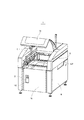
次に、本発明に係るスクリーン印刷機の一実施形態について、図面を参照しながら以下に説明する。図1及び図2は、本実施形態のスクリーン印刷機を示した斜視図であり、図1は上面開閉カバーのみが開いた状態が示され、図2には上面開閉カバーと前面開閉カバーが開いた状態が示されている。また、図3は、スクリーン印刷機の内部構造を簡易的に示した側面図である。このスクリーン印刷機1は、基板に対してクリームはんだを印刷するものであり、例えば印刷状態を検査する検査機や基板に電子部品の装着を行う部品装着機などと共に回路基板生産ラインを構成するものである。
Next, an embodiment of the screen printing machine according to the present invention will be described below with reference to the drawings. 1 and 2 are perspective views showing the screen printing machine of the present embodiment, FIG. 1 shows a state in which only the top opening / closing cover is open, and FIG. 2 shows a state in which only the top opening / closing cover and the front opening / closing cover are opened. The state is shown. Further, FIG. 3 is a side view simply showing the internal structure of the screen printing machine. This
スクリーン印刷機1は、機体内部に水平に設置されたマスクの下に基板が搬送および保持され、印刷パターン(貫通孔)を通してマスク上面から下側の基板にクリームはんだが塗布されるものである。そのスクリーン印刷機1は、図3に示すように上方にマスクホルダ2があり、そこにはマスク枠に固定されたマスクが保持されている。そして、マスクホルダの上方側にはスキージ装置3が設置され、機体前後方向である図3の左右方向に移動可能な状態で取り付けられている。一方、マスクホルダ2の下方側には基板用テーブル5が設置されている。基板用テーブル5には、基板を機体幅方向に搬入及び搬出させる搬送装置、基板を機体前後方向にクランプするクランプ装置、そして基板をクランプ位置へと上下させるバックアップ装置などが構成されている。
In the
更に、基板用テーブル5は、駆動モータ11とボールネジ機構を介して矢印A1で示す範囲において昇降可能な構成になっている。また、マスクホルダ2と基板用テーブル5の間には、マスクの汚れを下面側から拭き取って清掃するクリーニング装置6と、基板やマスクに付されたマークを撮像するためカメラユニット7が設けられている。クリーニング装置6とカメラユニット7はスライダを介して一体的に構成され、機体前後方向に配置されたガイドレールに沿って移動できるようになっている。例えば、一対のプーリに掛け渡された回転ベルトにクリーニング装置6とカメラユニット7とが連結され、駆動モータの回転制御により矢印A2に示す範囲において機体前後方向の移動が可能になっている。
Further, the substrate table 5 is configured to be able to move up and down within the range indicated by the arrow A1 via the
このようなスクリーン印刷機1は、全体が機体カバー8によって覆われており、幅方向の両側面に基板の搬入又は搬出のための搬送口801が形成されている。従って、回路基板生産ラインの上流側の搬送口801から搬送装置によって搬入された基板は、バックアップ装置によって持ち上げられた後クランプ装置によって保持され、その状態で更にマスク下の印刷位置へと基板用テーブル5ごと上昇する。そして、スキージ装置3によってマスクの印刷パターンを通してクリームはんだが基板に対して印刷される。その後、搬送位置に戻された基板は下流側の搬送口801から搬出されて次の部品実装機などへと送られる。
The entire
こうした基板への印刷処理が繰り返される際、クリーニング装置6およびカメラユニット7は、基板用テーブル5が図3に示すように下降した状態で矢印A2に示す機体前後方向に移動することとなる。このときカメラユニット7によって基板の認識マークなどが撮像され、或いは所定のタイミングでクリーニング装置6によるマスク下面の拭き取り清掃が行われる。このクリーニング装置6およびカメラユニット7は、基板用テーブル5とマスクホルダ2との間に位置しているため、上昇する基板用テーブル5の妨げとならないようにする必要がある。そこで、クリーニング装置6およびカメラユニット7は、図3に示すように機体前部に設けられた退避場所に移動し、上昇する基板用テーブル5との干渉が回避できるようになっている。
When the printing process on the substrate is repeated, the
スクリーン印刷機1は、柱部材や梁部材などが組まれた骨組み12が形成され、そこに前記各装置が組み付けられるとともに、機体カバー8が全体を覆うようにして取り付けられている。そして、機体カバー8に覆われた機内前部には、前述した退避場所を確保するため、図2及び図3において破線で示す空きスペースである機内前部スペース10が設けられている。骨組み12の機体前部分は、左右両側が突出し、その間の中央部分において機内前部スペース10ができるように、平面視で見た場合にコの字状に凹んだ形状になっている。そして、骨組み12が凹んだ構造であっても、クリーニング装置6などの退避場所を確保するため、機体カバー8はスクリーン印刷機1の前面全体がほぼ同じ位置の平面になっている。つまり、前記特許文献1に記載のスクリーン印刷機のように機体カバーの前面が凹んだ形状にはなっていない。
In the
ところで、スクリーン印刷機1では、作業者によって基板用テーブル5におけるバックアップ装置の段取り替えや機内のメンテナンスなどが行われる。その際、スクリーン印刷機1の前方から行う作業者の作業が行い易いように、本実施形態では機体カバー8の一部が扉タイプの開閉構造になっている。具体的には、機体の前面から上面にかけて開放するようにした上面開閉カバー15だけではなく、機体の前面も開放するようにした前面開閉カバー16が形成されている。すなわち、図2に示すように上面開閉カバー15と前面開閉カバー16が開くことにより、作業者は、機内前部スペース10内に一歩踏み込んだ立ち位置で作業を行うことができるようになっている。
By the way, in the
この点、従来のスクリーン印刷機は前面が固定面になっているため、作業者は図1に示すような前面カバーのある機体の前方に立つことになり、機内奥にある遠い位置の基板用テーブル5などに対し、大きく腰を折って前傾姿勢になったり、大きく手を伸ばして作業を行う必要があった。前記特許文献1に記載のスクリーン印刷機の場合でも、一部にシャッタは形成されているものの機体カバーの前面は固定されており、作業者の立ち位置から基板用テーブルまでの距離は近くなっていなかった。つまり、機体カバーの形状がコの字に形成されていても、クリーニング装置の退避場所が本実施形態と同様に設けられているため(特許文献1の図1参照)、凹んだ機体外側の位置から基板用テーブルまでの距離が近くなっているわけではないからである。
In this regard, since the front surface of the conventional screen printing machine is a fixed surface, the operator stands in front of the machine body having the front cover as shown in FIG. 1, and is used for a board at a distant position in the back of the machine. It was necessary to bend the waist greatly and lean forward with respect to the table 5 or the like, or to reach out and perform the work. Even in the case of the screen printing machine described in
そこで、本実施形態では、機体カバー8に対して片開き扉タイプの前面開閉カバー16を設けることにより、内部の機内前部スペース10を作業者が作業する際に使える空間として機能させることとした。この機内前部スペース10は、例えば幅が800mm程度あり作業者が入るのに十分な空間になっている。その一方で、作業者が機内に入ることを可能にした構造では、安全に作業が行えるよう注意する必要がある。そこで、本実施形態のスクリーン印刷機1には安全装置が設けられている。先ず、図2に示すように、前面開口部には前面開閉カバー16の開状態を検出する検出スイッチ25が取り付けられ、開状態を検出して送信される検出信号によって各装置の駆動停止制御が行われるようになっている。
Therefore, in the present embodiment, by providing the front opening /
また、前面開閉カバー16は、その裏側に安全アーム26が取り付けられている。ここで、図4は、安全アーム26の動作を簡易的に示した図である。特に、スクリーン印刷機1の前部を平面的に示したものであり、破線で機内前部スペース10が示されている。そして、前面開閉カバー16と安全アーム26は、その前面開閉カバー16の開いた状態が実線で示され、閉じた状態が一点鎖線で示されている。
A
この安全アーム26は、2本の帯状プレート261,262が互いに蝶番によって連結され、更に帯状プレート261の端部が前面開閉カバー16の裏面に蝶番を介して取り付けられ、もう一方の帯状プレート262の端部が機内の骨組み12に対して蝶番によって取り付けられている。従って、安全アーム26は、前面開閉カバー16の開閉に伴って帯状プレート261,262の角度を変えた変形が可能になっている。
The
具体的には、前面開閉カバー16が開いた場合は、図2及び図4に示すように、帯状プレート261,262の間の角度が大きく直線に近い形状になって前面開閉カバー16に沿うように配置されることとなる。そして、安全アーム26が機内前部スペース10を僅かに横切る程度の位置に配置されるようになっている。一方、前面開閉カバー16が閉じた場合には、図4の破線で示すように、帯状プレート261,262の間の角度が鋭角に折れた形状になって前面開閉カバー16から離れ、機内前部スペース10内に突き出すようにして配置されることとなる。
Specifically, when the front opening /
よって、安全アーム26は、前面開閉カバー16が開いた場合には、機内前部スペース10に立って作業する作業者の邪魔にならない配置となる一方、前面開閉カバー16が閉じる場合には、機内前部スペース10内に居る作業者に安全アーム26が当たるようになっている。つまり、作業者が機内前部スペース10で作業を行っている場合は、安全アーム26が邪魔になって前面開閉カバー16が閉じられないようになっている。なお、この安全装置は、前面開閉カバー16が開いた状態で機内前部スペース10との干渉が小さくなるように配置し、閉じた場合には逆に干渉する位置に突き出して作業者に当たるようにするものであれば、安全アーム26のような構成に限るものではない。
Therefore, the
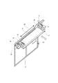
続いて、図5及び図6は、機体カバー8の前面開閉カバー16を裏面側から示した斜視図であり、特に図5は、退避場所に位置するクリーニング装置6との関係が示され、図6は、クリーニング装置6に対して溶剤を供給する溶剤供給装置を搭載した状態が示されている。クリーニング装置6は、白抜き矢印で示すようにスクリーン印刷機1の前後方向に往復移動することにより、クリーニングペーパ21によってマスクの汚れを下面側から拭き取るようにしたものである。具体的には、使用前のクリーニングペーパ21が第1ローラ23から巻き出され、拭き取りを行って使用済みとなった部分が第2ローラ24によって巻き取られるように構成されている。そして、第1ローラ23と第2ローラ24は平行に回転支持されており、両者にまたがって巻かれたクリーニングペーパ21は、その中間部分がマスク下面に押し当てられるようになっている。
Subsequently, FIGS. 5 and 6 are perspective views showing the front opening /
クリーニングペーパ21は、マスクに直接当たる拭き取り部分に対して、溶剤供給装置9よって溶剤が塗布される。溶剤供給装置9は、図6に示すように前面開閉カバー16に組み付けられており、クリーニングペーパ21に対する溶剤の塗布は、図5に示すように、クリーニング装置6の退避場所である前面開閉カバー16に接近した位置で行われることとなる。その溶剤供給装置9は、図2に示すように、溶剤を入れた溶剤タンク31が機内前部スペース10に位置するケース32内に入れられている。骨組み12の柱部材に固定されているケース32は前面が開いており、前面開閉カバー16には対応する個所に開口部161が形成されているため、前面開閉カバー16が閉じた状態でも溶剤タンク31の取り替えが可能になっている。
In the cleaning
下方に位置する溶剤タンク31は上方に位置するノズル33に対してフレキシブルなチューブによって接続され、溶剤タンク31内部の溶剤はポンプによって汲み上げられてノズル33から吐出されるようになっている。ノズル33が設けられた溶剤供給装置9の駆動部は一枚の支持プレート35に組み付けられ、その支持プレート35を介して前面開閉カバー16に取り付けられている。支持プレート35にはガイドレール36が水平に固定され、そのガイドレール36には摺動可能なガイドブロック37が嵌め合わされている。そして、ガイドブロック37にはノズル33を備えた走行台34が固定されている。
The
また、支持プレート35にはサーボモータ38が固定され、その回転軸に固定されたプーリに回転ベルト39が掛け渡されている。その回転ベルト39は、さらに支持プレート35に取り付けられた他のプーリ41,42やテンションローラ43などにも掛け渡されている。走行台34は、そうした回転ベルト39の直線部分391に連結されている。よって、溶剤供給装置9は、サーボモータ38の駆動制御により回転ベルト39が回転することで走行台34が引っ張られ、前面開閉カバー16の上方を縁に沿った矢印A3で示す移動が可能になっている。また、溶剤タンク31とノズル33を連結するチューブには電磁弁が接続されており、その開閉制御によってノズル33から吐出される溶剤の調整が行われるようになっている。
A
以上、本実施形態のスクリーン印刷機1では、前述したように上面開閉カバー15だけではなく前面開閉カバー16が構成されているため、段取り替えやメンテナンスの際、作業者は、上面開閉カバー15と前面開閉カバー16を開けて機内前部スペース10内に一歩踏み込んだ立ち位置で作業を行うことができる。その場合、クリーニング装置6やカメラユニット7は、機体後方(図3右側)に移動している。従って、作業者の立ち位置から作業箇所までの距離が短くなり、例えば手元が見やすくなるほか大きく腰を折った前傾姿勢にならずに作業を行うことができるなど、作業性が向上することとなる。
As described above, in the
また、前面開閉カバー16は片開き扉タイプであって、ネジ止めするような完全取り外しタイプではないため、容易に開け閉めを行うことができる。つまり、工具などを使用することなく開閉させることができ、作業者による作業性を損なうことがない。しかし、開け閉めが容易であるため開状態のままスクリーン印刷機1が駆動してしまうおそれがあるが、この点本実施形態では検出スイッチ25の検出によって各装置の駆動停止制御が行われる。従って、前面開閉カバー16の閉め忘れだけではなく、不意に開いてしまったような場合でもスクリーン印刷機1の駆動が停止することとなる。そして、万一機内前部スペース10内に作業者が居る状態で前面開閉カバー16が閉じられようとしても、安全アーム26によって前面開閉カバー16が閉じてしまうこともない。
Further, since the front opening /
更に、本実施形態では前面開閉カバー16が片開き扉タイプであるため、裏面に溶剤供給装置9を取り付けても取り扱いに不都合がないものとなった。つまり、前記特許文献1のようなシャッタ式では溶剤供給装置9を取り付けは困難であり、ネジ止めする完全取り外しタイプではチューブやケーブルの切り離しが必要になるなど作業者による作業性を損なってしまう。これに対して本実施形態では、支持プレート35に組み付けられた溶剤供給装置9の駆動部は前面開閉カバー16の開閉に従って旋回するが、ノズル33に接続されたチューブやサーボモータ38に接続されたケーブルなどを切り離す必要がなく、段取り替えなどを行う作業者に余分な作業を与えなることはない。しかも前面開閉カバー16が開いた状態で、機内前部スペース10で溶剤供給装置9が作業を行う作業者の妨げにもならない。
Further, in the present embodiment, since the front opening /
続いて、スクリーン印刷機の他の参考例につて図7を示して説明する。図7は、スクリーン印刷機の参考例を示す斜視図である。このスクリーン印刷機100は、図3で示す前記実施形態のスクリーン印刷機1と同様の内部構造を有し、全体が機体カバー108によって覆われている。機体カバー108には、機体の前面から上面にかけて開放するようにした上面開閉カバー115と、機体の前面も開放するようにした前面開閉カバー116が形成されている。しかし、本参考例の前面開閉カバー116は、前面カバー112の一部分だけであり、その開口部が上面開閉カバー115の開口部と連続するように上部に形成されている。
Subsequently, FIG. 7 will be described with reference to another reference example of the screen printing machine. FIG. 7 is a perspective view showing a reference example of the screen printing machine. The
上面開閉カバー115と前面開閉カバー116は、閉じた状態では実線で示すようにスクリーン印刷機100の外殻を構成し、開く時には、破線で示すように上面開閉カバー115が上側後方に回転し、前面開閉カバー116は下側前方に回転する構成になっている。さらに前面開閉カバー116は、回転軸部分にフリーストップヒンジなどが用いられているため、勢いよく開いてしまうことなく、また、任意の角度で回転を停止させて開状態の姿勢を保つことができるようになっている。
The top opening /
よって、スクリーン印刷機100では、上面開閉カバー115と前面開閉カバー116を全開させることにより、段取り替えやメンテナンスの際、作業者は前面開閉カバー116の開口部に体を入れて無理のない前傾姿勢をとることができ、機内奥の作業も可能になる。また、前面開閉カバー116を開けることで、出し入れするマスクの下側に余裕ができるため交換作業が行い易くなる。また、前面開閉カバー116を開けた開口部からクリーニング装置のクリーニングペーパの出し入れができるようにすることで、生産を停止させることなく作業を進めることが可能になる。また、前面開閉カバー116による開口部の面積が小さいため、開閉による機内の温度変化を最小限に抑えることができる。更に、前面開閉カバー116は、フリーストップヒンジによって回転軸部分が構成されているため、開く時に自重によって勢いよく全開状態になってしまうことがなく、作業者の手が挟まれたり、装置に傷がついたりすることを回避できる。また、前面開閉カバー116は任意の回転角度で停止可能な構成であるため、ストッパ機構を用い水平姿勢で位置決めすることにより作業台として使用することが可能になる。
Therefore, in the
以上、本発明の一実施形態について説明したが、本発明はこれに限定されることなく、その趣旨を逸脱しない範囲で様々な変更が可能である。
例えば、前記実施形態では、安全装置の一つとして安全アーム26を採用したが、それに替えて作業者の存在を確認するための光センサなどを設置するようにしてもよい。
また、機内前部スペース10は、前面開閉カバー16を閉じることで収納空間にもなるため、安全アーム26などの安全装置に干渉しないように、容易に取出し可能な収納部を構成するようにしてもよい。
Although one embodiment of the present invention has been described above, the present invention is not limited to this, and various modifications can be made without departing from the spirit of the present invention.
For example, in the above-described embodiment, the
Further, since the
1…スクリーン印刷機 2…マスクホルダ 3…スキージ装置 5…基板用テーブル 6…クリーニング装置 7…カメラユニット 8…機体カバー 9…溶剤供給装置 10…機内前部スペース 15…上面開閉カバー 16…前面開閉カバー 26…安全アーム 31…溶剤タンク 33…ノズル
1 ...
Claims (5)
機内全体を覆う機体カバーは、機体上面に配置された上面開閉カバーと、機体前面に配置された前面開閉カバーとを備えるものであり、
機体前部分の骨組みを左右両側に突出させて機内側に凹んだ空間を形成することにより、前記前面開閉カバーの内側に作業者が踏み込んで作業を行う機内前部スペースが設けられたものであることを特徴とするスクリーン印刷機。 In a screen printing machine that prints cream solder on a substrate using a mask in which a printing pattern consisting of a plurality of through holes is formed.
The fuselage cover that covers the entire inside of the aircraft includes a top opening / closing cover arranged on the upper surface of the aircraft and a front opening / closing cover arranged on the front surface of the aircraft.
By projecting the skeleton of the front part of the machine to both the left and right sides to form a recessed space inside the machine, a space for the front part of the machine is provided inside the front opening / closing cover so that the operator can step on and work. A screen printing machine that features that.
前記前面開閉カバーは、鉛直方向の軸によって手前側に開く開閉扉であり、その裏面に所定の作業機器が搭載されたものであることを特徴とする請求項1に記載するスクリーン印刷機。 The upper surface opening / closing cover is an opening / closing door that opens so as to be flipped upward by a horizontal axis.
The screen printing machine according to claim 1, wherein the front opening / closing cover is an opening / closing door that opens toward the front side by an axis in a vertical direction, and a predetermined work device is mounted on the back surface thereof.
機内全体を覆う機体カバーは、機体上面に配置された上面開閉カバーと、機体前面に配置された前面開閉カバーとを備えるものであり、
前記前面開閉カバーの内側に作業者の侵入可能な機内前部スペースが設けられ、
前記前面開閉カバーの裏面に取り付けられ開閉に伴い形態を変化させる変形構造であり、前記前面開閉カバーが閉じた時に前記機内前部スペースに突き出すようにして存在する安全手段を備えたものであるスクリーン印刷機。 In a screen printing machine that prints cream solder on a substrate using a mask in which a printing pattern consisting of a plurality of through holes is formed.
The fuselage cover that covers the entire inside of the aircraft includes a top opening / closing cover arranged on the upper surface of the aircraft and a front opening / closing cover arranged on the front surface of the aircraft.
An in-flight front space is provided inside the front opening / closing cover so that an operator can enter.
A screen having a deformed structure that is attached to the back surface of the front opening / closing cover and changes its shape as the front opening / closing cover is opened and closed, and is provided with a safety means that exists so as to protrude into the front space inside the machine when the front opening / closing cover is closed. Printing machine .
Priority Applications (1)
| Application Number | Priority Date | Filing Date | Title |
|---|---|---|---|
| JP2016041694A JP6777406B2 (en) | 2016-03-04 | 2016-03-04 | Screen printing machine |
Applications Claiming Priority (1)
| Application Number | Priority Date | Filing Date | Title |
|---|---|---|---|
| JP2016041694A JP6777406B2 (en) | 2016-03-04 | 2016-03-04 | Screen printing machine |
Publications (2)
| Publication Number | Publication Date |
|---|---|
| JP2017154445A JP2017154445A (en) | 2017-09-07 |
| JP6777406B2 true JP6777406B2 (en) | 2020-10-28 |
Family
ID=59809109
Family Applications (1)
| Application Number | Title | Priority Date | Filing Date |
|---|---|---|---|
| JP2016041694A Active JP6777406B2 (en) | 2016-03-04 | 2016-03-04 | Screen printing machine |
Country Status (1)
| Country | Link |
|---|---|
| JP (1) | JP6777406B2 (en) |
Families Citing this family (4)
| Publication number | Priority date | Publication date | Assignee | Title |
|---|---|---|---|---|
| JP6971033B2 (en) * | 2017-01-24 | 2021-11-24 | 株式会社Fuji | Screen printing machine |
| WO2020044388A1 (en) | 2018-08-27 | 2020-03-05 | 株式会社Fuji | Solder printing machine |
| US11607877B2 (en) * | 2019-04-26 | 2023-03-21 | Fuji Corporation | Printing device, cleaning unit, and control method for printing device |
| JPWO2022224431A1 (en) * | 2021-04-23 | 2022-10-27 |
Family Cites Families (4)
| Publication number | Priority date | Publication date | Assignee | Title |
|---|---|---|---|---|
| US5792268A (en) * | 1993-07-02 | 1998-08-11 | Sci Systems, Inc. | Printered circuit board screen printer vacuum holding apparatus |
| JP5349740B2 (en) * | 2006-05-26 | 2013-11-20 | デュプロ精工株式会社 | Stencil printing machine |
| JP4840422B2 (en) * | 2008-09-04 | 2011-12-21 | パナソニック株式会社 | Electronic component mounting apparatus and work method by electronic component mounting apparatus |
| US8746139B2 (en) * | 2010-12-08 | 2014-06-10 | Illinois Tool Works Inc. | Combination stencil printer and dispenser and related methods |
-
2016
- 2016-03-04 JP JP2016041694A patent/JP6777406B2/en active Active
Also Published As
| Publication number | Publication date |
|---|---|
| JP2017154445A (en) | 2017-09-07 |
Similar Documents
| Publication | Publication Date | Title |
|---|---|---|
| JP6777406B2 (en) | Screen printing machine | |
| JP7030967B2 (en) | Storage device and printing system | |
| JP5895874B2 (en) | Robot system | |
| JP6432036B2 (en) | Component mounting equipment | |
| TWI556879B (en) | Spray system and overturning device thereof | |
| JP6971033B2 (en) | Screen printing machine | |
| US20110098840A1 (en) | Parts mounting related work device | |
| JP6867365B2 (en) | A robot system equipped with a reel holding device and a reel holding device arranged in a component mounting machine. | |
| TW201919915A (en) | Screen printing device and screen printing method | |
| JP2011016339A (en) | Screen printing machine | |
| WO2011083765A1 (en) | Screen printing machine | |
| US20180086582A1 (en) | Film supplying device in horizontal package making and filling machine | |
| KR101475253B1 (en) | Gantry work apparatus | |
| JP5755536B2 (en) | Electronic component mounting equipment | |
| US9215836B2 (en) | Printed circuit board production apparatus and printing machine | |
| JP3880850B2 (en) | Screen printing machine | |
| JP2019009474A (en) | Part mounting apparatus | |
| JP2017087433A (en) | Sheet-like object inspection device | |
| JP2002029023A (en) | Auxiliary device of printing unit | |
| JP4551008B2 (en) | Cover device for component supply unit in electronic component mounting device | |
| JP2018528100A (en) | Printing unit and method for arranging at least one suction box in a printing unit | |
| JP5219052B2 (en) | Supply conveyor for horizontal bag making and filling machine | |
| US5282416A (en) | Versatile tile-slide squeegee drive apparatus | |
| JP2024084186A (en) | Protective covers and work | |
| US20240246347A1 (en) | Printing device |
Legal Events
| Date | Code | Title | Description |
|---|---|---|---|
| A621 | Written request for application examination |
Free format text: JAPANESE INTERMEDIATE CODE: A621 Effective date: 20190215 |
|
| A977 | Report on retrieval |
Free format text: JAPANESE INTERMEDIATE CODE: A971007 Effective date: 20191225 |
|
| A131 | Notification of reasons for refusal |
Free format text: JAPANESE INTERMEDIATE CODE: A131 Effective date: 20200107 |
|
| A601 | Written request for extension of time |
Free format text: JAPANESE INTERMEDIATE CODE: A601 Effective date: 20200225 |
|
| A521 | Request for written amendment filed |
Free format text: JAPANESE INTERMEDIATE CODE: A523 Effective date: 20200421 |
|
| TRDD | Decision of grant or rejection written | ||
| A01 | Written decision to grant a patent or to grant a registration (utility model) |
Free format text: JAPANESE INTERMEDIATE CODE: A01 Effective date: 20200923 |
|
| A61 | First payment of annual fees (during grant procedure) |
Free format text: JAPANESE INTERMEDIATE CODE: A61 Effective date: 20201008 |
|
| R150 | Certificate of patent or registration of utility model |
Ref document number: 6777406 Country of ref document: JP Free format text: JAPANESE INTERMEDIATE CODE: R150 |
|
| R250 | Receipt of annual fees |
Free format text: JAPANESE INTERMEDIATE CODE: R250 |
|
| R250 | Receipt of annual fees |
Free format text: JAPANESE INTERMEDIATE CODE: R250 |