EP3960420A1 - Hook fastener connector - Google Patents
Hook fastener connector Download PDFInfo
- Publication number
- EP3960420A1 EP3960420A1 EP21170163.6A EP21170163A EP3960420A1 EP 3960420 A1 EP3960420 A1 EP 3960420A1 EP 21170163 A EP21170163 A EP 21170163A EP 3960420 A1 EP3960420 A1 EP 3960420A1
- Authority
- EP
- European Patent Office
- Prior art keywords
- hook
- loop fastener
- base plate
- head
- molds
- Prior art date
- Legal status (The legal status is an assumption and is not a legal conclusion. Google has not performed a legal analysis and makes no representation as to the accuracy of the status listed.)
- Withdrawn
Links
Images


Classifications
-
- B—PERFORMING OPERATIONS; TRANSPORTING
- B29—WORKING OF PLASTICS; WORKING OF SUBSTANCES IN A PLASTIC STATE IN GENERAL
- B29C—SHAPING OR JOINING OF PLASTICS; SHAPING OF MATERIAL IN A PLASTIC STATE, NOT OTHERWISE PROVIDED FOR; AFTER-TREATMENT OF THE SHAPED PRODUCTS, e.g. REPAIRING
- B29C45/00—Injection moulding, i.e. forcing the required volume of moulding material through a nozzle into a closed mould; Apparatus therefor
- B29C45/17—Component parts, details or accessories; Auxiliary operations
- B29C45/26—Moulds
- B29C45/2626—Moulds provided with a multiplicity of narrow cavities connected to a common cavity, e.g. for brushes, combs
-
- A—HUMAN NECESSITIES
- A44—HABERDASHERY; JEWELLERY
- A44B—BUTTONS, PINS, BUCKLES, SLIDE FASTENERS, OR THE LIKE
- A44B18/00—Fasteners of the touch-and-close type; Making such fasteners
- A44B18/0046—Fasteners made integrally of plastics
- A44B18/0049—Fasteners made integrally of plastics obtained by moulding processes
-
- A—HUMAN NECESSITIES
- A44—HABERDASHERY; JEWELLERY
- A44B—BUTTONS, PINS, BUCKLES, SLIDE FASTENERS, OR THE LIKE
- A44B18/00—Fasteners of the touch-and-close type; Making such fasteners
- A44B18/0046—Fasteners made integrally of plastics
- A44B18/0061—Male or hook elements
-
- B—PERFORMING OPERATIONS; TRANSPORTING
- B29—WORKING OF PLASTICS; WORKING OF SUBSTANCES IN A PLASTIC STATE IN GENERAL
- B29C—SHAPING OR JOINING OF PLASTICS; SHAPING OF MATERIAL IN A PLASTIC STATE, NOT OTHERWISE PROVIDED FOR; AFTER-TREATMENT OF THE SHAPED PRODUCTS, e.g. REPAIRING
- B29C33/00—Moulds or cores; Details thereof or accessories therefor
- B29C33/42—Moulds or cores; Details thereof or accessories therefor characterised by the shape of the moulding surface, e.g. ribs or grooves
-
- B—PERFORMING OPERATIONS; TRANSPORTING
- B29—WORKING OF PLASTICS; WORKING OF SUBSTANCES IN A PLASTIC STATE IN GENERAL
- B29C—SHAPING OR JOINING OF PLASTICS; SHAPING OF MATERIAL IN A PLASTIC STATE, NOT OTHERWISE PROVIDED FOR; AFTER-TREATMENT OF THE SHAPED PRODUCTS, e.g. REPAIRING
- B29C45/00—Injection moulding, i.e. forcing the required volume of moulding material through a nozzle into a closed mould; Apparatus therefor
- B29C45/17—Component parts, details or accessories; Auxiliary operations
- B29C45/40—Removing or ejecting moulded articles
- B29C45/44—Removing or ejecting moulded articles for undercut articles
- B29C45/4407—Removing or ejecting moulded articles for undercut articles by flexible movement of undercut portions of the articles
-
- B—PERFORMING OPERATIONS; TRANSPORTING
- B29—WORKING OF PLASTICS; WORKING OF SUBSTANCES IN A PLASTIC STATE IN GENERAL
- B29C—SHAPING OR JOINING OF PLASTICS; SHAPING OF MATERIAL IN A PLASTIC STATE, NOT OTHERWISE PROVIDED FOR; AFTER-TREATMENT OF THE SHAPED PRODUCTS, e.g. REPAIRING
- B29C45/00—Injection moulding, i.e. forcing the required volume of moulding material through a nozzle into a closed mould; Apparatus therefor
- B29C2045/0094—Injection moulding, i.e. forcing the required volume of moulding material through a nozzle into a closed mould; Apparatus therefor injection moulding of small-sized articles, e.g. microarticles, ultra thin articles
-
- B—PERFORMING OPERATIONS; TRANSPORTING
- B29—WORKING OF PLASTICS; WORKING OF SUBSTANCES IN A PLASTIC STATE IN GENERAL
- B29L—INDEXING SCHEME ASSOCIATED WITH SUBCLASS B29C, RELATING TO PARTICULAR ARTICLES
- B29L2031/00—Other particular articles
- B29L2031/727—Fastening elements
- B29L2031/729—Hook and loop-type fasteners
-
- B—PERFORMING OPERATIONS; TRANSPORTING
- B60—VEHICLES IN GENERAL
- B60N—SEATS SPECIALLY ADAPTED FOR VEHICLES; VEHICLE PASSENGER ACCOMMODATION NOT OTHERWISE PROVIDED FOR
- B60N3/00—Arrangements or adaptations of other passenger fittings, not otherwise provided for
- B60N3/04—Arrangements or adaptations of other passenger fittings, not otherwise provided for of floor mats or carpets
- B60N3/046—Arrangements or adaptations of other passenger fittings, not otherwise provided for of floor mats or carpets characterised by the fixing means
-
- Y—GENERAL TAGGING OF NEW TECHNOLOGICAL DEVELOPMENTS; GENERAL TAGGING OF CROSS-SECTIONAL TECHNOLOGIES SPANNING OVER SEVERAL SECTIONS OF THE IPC; TECHNICAL SUBJECTS COVERED BY FORMER USPC CROSS-REFERENCE ART COLLECTIONS [XRACs] AND DIGESTS
- Y10—TECHNICAL SUBJECTS COVERED BY FORMER USPC
- Y10T—TECHNICAL SUBJECTS COVERED BY FORMER US CLASSIFICATION
- Y10T428/00—Stock material or miscellaneous articles
- Y10T428/24—Structurally defined web or sheet [e.g., overall dimension, etc.]
- Y10T428/24008—Structurally defined web or sheet [e.g., overall dimension, etc.] including fastener for attaching to external surface
- Y10T428/24017—Hook or barb
Definitions
- the invention relates to a device for producing a hook and loop fastener connecting part by means of an injection molding process, an injection molding method for producing a hook and loop fastener connecting part, and a hook and loop fastener connecting part.
- a hook and loop fastener connection part which has a large number of Velcro hooks, is contacted with a loop element or fleece part, which has loops or fibers, as a result of which the Velcro hooks hook into the loops or fibers.
- This connection can be released again by pulling the loop element off the hook and loop fastener connection part.
- This reversibly detachable connection is used in many areas for releasably attaching objects or components.
- floor mats on the vehicle floor are secured against slipping or lifting by means of a Velcro connection in motor vehicles by fastening means being anchored to the floor of the interior of the vehicle, which have a hook and loop fastener connection part that when contacting a Velcro part of a floor mat allows a reversible attachment of the floor mat to the vehicle floor.
- a hook-and-loop fastener connection in the form of a fastening device for a motor vehicle floor mat is conventionally provided in that a base body with a large number of hook-and-loop hooks is glued to a support part that is circular, for example, by means of chemical or thermal adhesive connections, for example with solvent-based adhesives or hot-melt glue, and this support part is attached to the Floor of the vehicle interior fastened with a fastener.
- chemical or thermal adhesive connections for example with solvent-based adhesives or hot-melt glue
- WO 2014/191089 A1 discloses an injection molding tool and method in which, in the first step, a closure part forming a component of a touch-and-close fastener with adhesion and/or hooking elements is produced and introduced into the injection mold as an insert, and in a second step a carrier part is formed by means of a foamed plastic material , which connects to the insert. That is, the insert and carrier part of WO 2014/191089 are not formed in one piece.
- DE 10 2009 054 896 A1 discloses a tool for producing a Velcro plate using an injection molding process, with which the Velcro hooks are formed together with the Velcro plate in one step.
- the Velcro hooks are arranged perpendicularly on the plate-shaped base plate of the Velcro plate. Due to this vertical arrangement, the Velcro hooks are formed with a hook head, which has approximately half the cross section of the hook foot, since the hook head is only in the second part of the tool Tool can be formed, because otherwise the first and second tool parts of the tool would not be mutually displaceable after injection molding of the Velcro plate.
- a device for producing a hook and loop fastener connecting part by means of an injection molding process comprising: An injection mold having a plurality of first and second half molds, each first half mold having a plurality of first cavities in a first surface and each second half mold having a plurality of second cavities in a second surface, and first and second surfaces facing and contacting so that the first and second cavity together form an overall cavity in the shape of a hook, wherein the hook shape has a hook base and a hook head, and the hook base and hook head are arranged within one plane, the hook base being formed at least by the first cavity and the hook head being formed at least by the second cavity, wherein the injection mold has a longitudinal axis along which the second half molds can be displaced relative to the first half molds, characterized in that the plane and the longitudinal axis are angled towards each other.
- first and second half-moulds are formed in such a way that the plane within which the Hook foot and the hook head of the hook shape are arranged, and the longitudinal axis of the injection mold are angled to each other.
- this makes it possible for a hook that has been injection-molded in the injection mold to be easily removed or ejected from the first and second half-molds by moving the second half-molds relative to the first half-molds along the longitudinal axis of the injection mold, and makes it possible to provide an advantageous dimensioning of the hook head as well an advantageous angled arrangement of the injection molded hooks on the hook and loop fastener connection part.
- hook shape or “hook”, “half-shape” “surface” are mostly used in the singular, with one or one of the large number of “hook (shapes)", “half-shapes” or “surfaces” of the invention being used as an example device are meant.
- hook and loop fastener connecting part means an object having a large number of hooks, the hooks of which hook onto a loop element or looped part which has loops or fibers when it comes into contact. This creates a reversibly detachable connection between the hook and loop fastener connecting part and the loop element.
- hook head used here is to be understood as meaning a structure which enables hooking with a felt or fibrous structure of a loop element or fleece part.
- a structure can be a curved structure, for example a semicircular structure or a structure which is less than a semicircle, eg 1/3 circle, or more than a semicircle, eg a 5/8 circle.
- this structure can also have an angled or angular shape, such as an inverted V-shape, or an angular, inverted U-shape.
- the hook head preferably has a 1/3 to 5/8 circular shape.
- the hook shapes can also be formed as double hooks, which are obtained by forming two hook heads on a hook foot, and these hook feet point in 180° opposite directions.
- the term "hook foot” means a structure that connects the "hook head” to a body, such as a base plate, of the hook and loop fastener fastener.
- the "hook foot” preferably has a rectilinear structure. With a circularly curved hook head, the hook head begins where the curvature of the hook head begins. With an angular shape of the hook head, the hook foot ends and the hook head begins at a point where an imaginary line emanating from the end of the hook head intersects the hook foot as a perpendicular.
- the separation between hook head and hook foot by means of the point described above is purely schematic.
- part of the hook foot can fall below or exceed this schematic separation point along the longitudinal direction of the hook foot, e.g. if the hook head is formed in the second cavity of the second half mold and the hook foot is formed in the first cavity of the first half mold and in the second cavity the second half mold is formed.
- longitudinal axis of the injection mold used here is to be understood as meaning an axis along which the second half-molds can be displaced relative to the first half-molds. This means that the displacement of the first and second half molds can take place on or parallel to the longitudinal axis of the injection mold.
- the longitudinal axis of the injection mold is perpendicular to a surface of the injection mold that forms the face of a base plate of the hook and loop fastener fastener on which the plurality of hooks are formed, which surface is preferably wholly or partially defined by the third surfaces of the first half molds described below and fourth surfaces of the second half molds.
- the device has the usual means of an injection molding device, such as means for heating the plastic to be injected into the injection mold, injection channels for the injection mold to press molten plastic into the injection mold, and means for appropriately opening and closing the injection mold.
- an injection molding device such as means for heating the plastic to be injected into the injection mold, injection channels for the injection mold to press molten plastic into the injection mold, and means for appropriately opening and closing the injection mold.
- the plane within which the hook foot and the hook head of the hook mold are arranged and the longitudinal axis of the injection mold are preferably angled to one another at an angle of up to 40°, more preferably 5° to 30°, and particularly preferably 10° to 20°.
- This preferred angling of plane and longitudinal axis is advantageous because it allows the injection-molded hook easier to remove or eject from the first and second cavities, and if necessary, thanks to this choice of angles, the hook head of the hook shape can be formed entirely in the second cavity.
- angles ⁇ given in connection with the angled arrangement of the plane and the longitudinal axis to one another also include negative angles, ie angled at -40° to one another, more preferably -5° to -30°, and particularly preferably -10° to -20 °.
- This means that the hook shapes can be formed in opposite directions within the first and second half shapes, ie once with a positive angle and once with a negative angle.
- first and second surfaces of the plurality of first and second half molds are arranged parallel to each other, more preferably parallel to the longitudinal axis.
- This parallel arrangement enables the first and second half molds to be designed in the same way, i.e. the design or manufacture of the first and second half molds is simpler compared to a non-parallel arrangement.
- the first and second surfaces of the plurality of first and second half molds are arranged parallel to one another in relation to the longitudinal axis. This makes it possible for both the first and the second half-moulds to be displaced upwards or downwards as desired along the longitudinal axis.
- the hook foot is formed by the first and second cavities and the hook head is formed by the second cavity.
- This has the advantage that the injection-molded hook can be easily removed or demoulded by moving the second half-mould relative to the first half-mould, since the hook head is formed completely in the second cavity, i.e. it can be pressed on the hook head by moving it, for example, in order to injection molded hook easy to remove or demould.
- the hook head is only formed in the second cavity, the hook head of the injection-molded hook cannot block the displacement of the first and second half molds relative to one another.
- the hook head preferably has a cross section or a cross-sectional area equal to or larger than the cross section or the cross-sectional area of the hook foot.
- injection mold means an overall cavity in the form of a hook and loop fastener connecting part, the plurality of first and second half molds forming the plurality of hooks of the hook and loop fastener connecting part and the surface of a base body when the injection mold is ejected with molten plastic will.
- the injection mold has one or more injection channels, which enable or enable the injection mold to be ejected with molten plastic.
- the main body of the hook and loop fastener connecting part can in principle have any shape, preferably the main body is formed in the form of a base plate, i.e. a planar body with a certain thickness on which the plurality of hooks are formed.
- the base body can have fastening means that allow the base body to be fastened with the plurality of hooks to a further object.
- the "injection mold” can thus represent an overall cavity which, in addition to the plurality of hooks formed by the plurality of first and second half molds and the surface of the base body on which the plurality of hooks is formed, also depicts the further shape of the base body with optional fastening means , so that a hook and loop fastener connecting part with a plurality of hooks and base body with optional fastening means can be integrally formed in the injection mold.
- the injection mold of the device according to the invention is preferably designed in such a way that the first half mold has a third surface and the second half mold has a fourth surface, and the third surface is adjacent to the first surface and the fourth surface is adjacent to the second surface, with the third and fourth Surface together form an opening that represents the cross section of the lower end of the hook base.
- This opening preferably opens into a further cavity in the form of a base plate of the hook and loop fastener connection part, so that when the injection mold is ejected, a hook and loop fastener connection part with a large number of hooks formed on the base plate is obtained.
- This configuration of the injection mold is advantageous for using a hook and loop fastener connection part a base plate on which a plurality of Velcro hooks are formed.
- the further cavity in the form of a base plate of the hook and loop fastener connection part can also have a cavity on a side opposite the third and fourth surfaces, which has the shape of a fastener, so that when the injection mold is ejected, a hook and loop fastener connection part with a plurality of hooks formed on the base plate, wherein the base plate is formed with a fastener on the side opposite to the side having the plurality of hooks.
- the third surface is perpendicular to the first surface and the fourth surface is perpendicular to the second surface. This enables the first and second half molds to be displaced in an advantageously simple manner in relation to one another, and thus also advantageously allows them to be removed or ejected from the injection mold.
- the second half molds are preferably displaceable towards the further cavity in the form of a base plate of the hook and loop fastener connecting part, while the first half molds maintain their position. This enables a particularly advantageous removal or demoulding. Because if the additional cavity in the form of a base plate is opened on the side opposite the first and second hook molds, pressure can be exerted on the injection-molded hook heads and the injection-molded base plate by means of the aforementioned displacement by means of the second half-molds, whereby the hook base of the injection-molded Hook is pushed out of the first cavity.
- At least one first half mold preferably has a first surface on each of two opposite sides, and at least one second half mold has a second surface on each of two opposite sides.
- the third and fourth surfaces are preferably planar. This enables the production of a hook and loop fastener part with a planar base plate.
- the first and second surfaces are preferably planar. This enables a simple design and manufacture of the first and second half molds and enables the first and second half molds to be easily displaced relative to one another.
- the second cavities are formed so that the ends of the hook head shapes have the same orientation, respectively.
- the first and second half molds are preferably arranged concentrically with one another, more preferably they are arranged concentrically with one another in a circle.
- Such a concentric arrangement has the advantage that when removing or ejecting by moving the concentric first and second half molds relative to one another, there is a relatively even distribution of forces when pressing on the injection-molded hook heads or the injection-molded base plate.
- first and second half-moulds are arranged circularly concentrically to one another, it is preferred that all second cavities are formed in such a way that all hook head shapes are formed essentially tangentially to the circular shape of the second half-mould and the ends of the hook head shapes each have the same orientation.
- "Essentially tangential" in this context means that the plane within which the hook base and hook head are arranged is perpendicular or with a tolerance of ⁇ 5° on a contact radius of the second half-shape. If a first half-mold has a first surface on two opposite sides and a second half-mold has a second surface on two opposite sides, this respective orientation can be either the same or opposite on both opposite sides, preferably opposite.
- a hook and loop fastener connection part is obtained by means of the device according to the invention, in which the plurality of hooks arranged concentrically in a circle form the ends of the hook heads tangentially to the circular shape have the same orientation, while in a circle adjacent to this circle of hooks the ends of the hook heads tangential to the circular shape have an orientation opposite to that of the adjacent circle.
- This circular concentric arrangement of hooks, in which the hook heads of adjacent circles each have an opposite tangential orientation to the circular shape is also referred to herein as "circular concentrically against each other". This arrangement enables a particularly advantageous, stable Velcro connection with a fleece part.
- the second half mold is formed in such a way that the hook head is formed as a double hook head, the hook heads of which point in 180° opposite directions.
- This has the advantage that a Velcro hook can be formed with 2 hook heads, which virtually doubles the stability of the Velcro connection compared to hooks with only one hook head.
- the cross-section or the cross-sectional area of the hook base and/or hook head can in principle have any shape, for example polygonal, such as triangular, square, pentagonal or hexagonal, essentially circular, or a mixed form of polygonal and essentially circular, e.g. a polygonal cross-section , in which the corners are rounded. It is preferred that the cross-section or the cross-sectional area of the hook base and/or hook head is essentially circular. “Essentially circular” here means circular, in the shape of a segment of a circle or oval, it being preferred for the cross section of the hook foot and/or hook head to be circular or in the shape of a segment of a circle.
- a cross section of the hook head in the shape of a segment of a circle can be formed, for example, in that the arc of the circle segment is formed by the second cavity of the second half-mould, and the chord of the circle segment is formed by a flat first surface of the first half-mould.
- the opening formed jointly by the third and fourth surfaces is preferably circular, and the third surface forms a circular segment with 60-80% of the circular shape of the opening, and the fourth surface forms a circular segment with 20-40% of the circular shape of the opening with which Provided that the total circular area of the opening is 100%.
- This advantageous configuration of the third and fourth surfaces makes it possible for a larger part of the cross section of the hook foot to be formed in the first half mold, while the second half mold forms a smaller part of the cross section of the hook foot.
- the dimensions of the hook shape explained below are selected in such a way that an injection-molded hook can be easily demolded or removed from the first or second half-molds without being damaged, for example by tearing off the hook head. Furthermore, due to the dimensions explained below the hook shape obtained during injection molding a hook, which ensures an advantageously stable Velcro connection with a fleece part.
- the first and second half-mould in particular the first cavity of the first half-mould and the second cavity of the second half-mould, are preferably dimensioned such that the circular cross-section of the hook base has a diameter of 0.3 to 0.8 mm, more preferably 0.4 to 0.7 mm, particularly preferably 0.45 to 0.6 mm.
- the first and second half mold are dimensioned in such a way that the hook head has a diameter equal to or larger than the diameter of the hook foot, preferably the hook head has up to 25% more diameter than the hook foot, preferably 4% up to 22% more, more preferably from 6 up to 18% more, most preferably from 8 up to 12% more.
- the diameter of the cross-section shaped like a segment of a circle of the hook head is selected in such a way that the cross-section shaped like a segment of a circle or cross-sectional area of the hook head is at least equal to or preferably larger than the circular cross-section or cross-sectional area of the hook foot is.
- the first and second half mold are dimensioned such that the hook mold has a height of 1.2 to 4 mm, more preferably 1.5 to 3 mm, particularly preferably 1.8 to 1.8 mm from the hook foot to the hook head 2.5mm This height from hook root to hook head is measured perpendicularly from the third and fourth surfaces to the highest point of the hook head of the hook shape.
- the further cavity in the form of a base plate of the hook and loop fastener connecting part is preferably circular and has a diameter of 5 to 10 cm and a thickness of 1 to 5 mm, more preferably a diameter of 6 to 8.5 cm and a thickness of 1, 5 to 4 mm, particularly preferably a diameter of 6 to 7.5 cm and a thickness of 2 to 3 mm.
- the thickness of the circular base given herein is exclusive of the optional fastener, which may be on the opposite side having the plurality of hooks.
- the hook and loop fastener connecting part is a fastening device for an automobile floor mat.
- a fastening device for a motor vehicle floor mat are explained in the description of the hook and loop fastener connecting part according to the invention.
- a device for producing a hook and loop fastener connecting part by means of an injection molding process which comprises: An injection mold having a plurality of first and second half molds, each first half mold having a plurality of first cavities in a first surface and each second half mold having a plurality of second cavities in a second surface, and first and second surfaces facing and contacting so that the first and second cavity together form an overall cavity in the shape of a hook, wherein the hook shape has a hook base and a hook head, and the hook base and hook head are arranged within one plane, the hook base being formed by the first and second cavities and the hook head being formed by the second cavity, wherein the injection mold has a longitudinal axis along which the second half molds can be displaced relative to the first half molds, wherein the first and second surfaces of the plurality of first and second half molds are arranged parallel to each other and parallel to the longitudinal axis, characterized in that the plane and the longitudinal axis are angled to one another at an
- the first half mold has a third surface and the second half mold has a fourth surface, and the third surface is adjacent to the first surface and the fourth surface is adjacent to the second surface, the third and fourth surfaces together forming an opening that represents the cross-section of the lower end of the hook foot, with this opening in another cavity in the form of a base plate of the hook and loop fastener connecting part, so that when the injection mold is ejected, a hook and loop fastener connecting part with a large number of hooks formed on the base plate is obtained, wherein the third surface is perpendicular to the first surface and the fourth surface is perpendicular to the second surface, and the third and fourth surfaces are planar.
- the invention relates to an injection molding method for producing a hook and loop fastener connecting part using the device according to the invention.
- the advantages of this injection molding process result from the advantages of the device already explained above.
- the injection molding process according to the invention does not differ from conventional injection molding processes with regard to process parameters such as the temperature(s) for melting a starting plastic and injection molding into the injection mold and with regard to the choice of plastic.
- a plastic can be selected as the starting plastic from the group of polyamides, polyalkylenes and thermoplastic copolymers, preferably the plastic is selected from the group of polyamide, polyethylene, polypropylene and acrylonitrile butadiene styrene (ABS), more preferably polyamide or polyethylene, particularly preferably polyamide 56 Process temperature(s) are chosen depending on the type of plastic used.
- the hook and loop fastener connecting part is preferably molded in one piece in the injection mold. That is, the hook and loop fastener connecting part can be formed in one step. This has the advantage that no further steps are required in order to attach the large number of hooks to a base body, e.g. in the form of a base plate, and/or to attach optional fastening means to the base body.
- the device according to the invention used in the method according to the invention has an injection mold with first and second half molds which are formed in such a way that the plane within which the hook base and the hook head of the hook mold are arranged and the longitudinal axis of the injection mold are angled towards one another. This facilitates the demoulding or ejection step c), because the hook feet can be easily pressed out of the injection mold or demoulded by the pressure exerted on the hook head by the displacement of the second half molds.
- the injection mold can be opened in the direction of the further cavity in the form of a base plate in order to enable the second half mold to be displaced in the direction of the base plate of the injection-molded hook and loop fastener connection part.
- the device or the injection mold can have a mechanism that allows the second half molds to be moved in step c) without the injection mold having to be opened before step c), e.g. a mechanism which, by moving the second half molds, opens the injection mold in the direction of the further cavity in the form of the base plate, in that the second half-molds exert pressure on the injection-molded base plate, and the injection mold opens in this way, for example by means of a resilient mechanism.
- the method according to the invention preferably comprises the following step: d) Pulling on the base plate of the hook and loop fastener connecting piece to pull out hook heads located in the second half molds.
- step d) serves to remove the hook heads from the mold.
- the pulling on the base plate of the hook and loop fastener fastener in step d) can be accomplished by any suitable means.
- the key advantage of step d) is that thanks to the injection mold with first and second half-moulds, which are formed in such a way that the plane within which the hook foot and the hook head of the hook mold are arranged and the longitudinal axis of the injection mold are angled towards each other allow the hook heads to be easily pulled out of the second half molds without being damaged in the process.
- the invention relates to a hook and loop fastener connecting part with a large number of hooks, which are arranged on a base plate, the hooks having a hook base and a hook head, and the hook base and a hook head being arranged within one plane, characterized in that the plane and the base plate are angled at an angle ⁇ greater than 90° to one another.
- Conventional hook and loop fastener fasteners have hook and loop fasteners formed at an angle of 90° on a base due to their manufacturing process.
- the present inventors have now surprisingly found that an angle greater than 90° not only offers advantages with regard to the device for production and the injection molding process, but that an angle greater than 90° also ensures an advantageous, particularly stable Velcro connection with a fleece part .
- the hook and loop fastener connecting member is preferably obtainable by the method of the present invention described above.
- the hook and loop fastener connection part can be produced with the advantages already mentioned, which were mentioned in connection with the device according to the invention and the method according to the invention.
- the angle ⁇ between the imaginary plane within which the foot and head of the hook are arranged and the base plate of the hook and loop fastener connecting part according to the invention corresponds to the angle ⁇ between the plane and the longitudinal axis of the injection mold of the device according to the invention when the hook and loop fastener connecting part according to the invention is produced using the method according to the invention .
- the plane and the base plate are angled at an angle ⁇ of greater than 90° to 130°, more preferably 95° to 120°, and more preferably 100° to 110°.
- an angle ⁇ of 95° to 120°, and in particular an angle of 100° to 110° is particularly advantageous with regard to the stability of the Velcro connection with a fleece part.
- the angles specified in connection with the angled arrangement of the plane and the base plate relative to one another also include negative angles, i.e.
- the plurality of hooks arranged on the base plate can also be formed in opposite directions, ie one with a positive angle and one with a negative angle.
- the hook and loop fastener connection part according to the invention is suitable for any application, such as in the leisure sector, in the household or in the industrial sector, e.g. in the automotive sector.
- the hook and loop fastener connecting part can have any shape suitable for the desired application, in particular the hook shape and hook dimensions as well as the shape of the base plate are selected accordingly, and fastening means optionally attached to the base plate can also be selected suitably depending on the area of application.
- the plurality of hooks may be arranged in a circular concentric manner on the base plate, preferably circularly concentric with each other.
- the hook and loop fastener connection part according to the invention is preferably a fastening device for a motor vehicle floor mat, the preferred embodiment of which is explained below.
- the hook and loop fastener connecting part is preferably a fastening device for a motor vehicle floor mat, which preferably has a fastening means for fastening the base plate to the floor of the interior of a motor vehicle on the side of the base plate which is opposite the side with the plurality of hooks, the base plate, the plurality of hooks and the fastener are integrally formed.
- the one-piece formation of the hook and loop fastener connection part has the advantage that the large number of hooks and the fastening means are an integral part of the hook and loop fastener connection part, which means that both the Velcro connection to a looped part and the attachment to the floor of the interior of a motor vehicle are much more stable than with one hook velcro connector part, wherein the plurality of hooks and/or the attachment means are separate parts which are subsequently attached to the base plate.
- the fastening means can have any shape as long as it is suitable for fastening the base plate to the floor of the interior of a motor vehicle.
- the fastening means is in the form of a screw or a T-shaped anchoring element.
- the dimensions of the hook, base plate and optional fastening means of the hook and loop fastener connecting part according to the invention can be suitably selected depending on the area of application.
- the hook and loop fastener connecting part preferably has hooks with a hook foot having a circular cross section with a diameter of 0.3 to 0.8 mm, more preferably 0.4 to 0.7 mm, particularly preferably 0.45 to 0.6 mm.
- the hook head of the hook of the hook and loop fastener connecting part is preferably designed in such a way that the hook head has a diameter equal to or larger than the diameter of the hook foot, preferably the hook head has up to 25% more diameter than the hook foot, preferably from 4% to 22% more, more preferably from 6 up to 18% more, most preferably from 8 up to 12% more.
- the diameter of the cross-section shaped like a segment of a circle of the hook head is selected in such a way that the cross-section shaped like a segment of a circle or cross-sectional area of the hook head is at least equal to or preferably larger than the circular cross-section or cross-sectional area of the hook foot is.
- the hook head Because if you try to loosen a Velcro connection with a piece of fleece, the hook head requires a higher pull-off force, partly because the hook head is more stable due to the advantageous dimensions and tears off the hook foot much less easily than a hook head, which has a smaller diameter than the hook foot .
- the hooks of the hook and loop fastener connecting part preferably have a height from the foot of the hook to the head of the hook of 1.2 to 4 mm, preferably 1.5 to 3 mm, particularly preferably 1.8 to 2.5 mm. This height from the foot of the hook to the head of the hook is measured perpendicularly from the base plate to the highest point of the head of the hook.
- the base plate of the hook and loop fastener connecting part is circular and has a diameter of 5 to 10 cm and a thickness of 1 to 5 mm, preferably a diameter of 6 to 8.5 cm and a thickness of 1.5 to 4 mm, particularly preferably a diameter of 6 to 7.5 cm and a thickness of 2 to 3 mm.
- the aforementioned thickness of the base plate relates exclusively to the base plate itself, ie the large number of hooks arranged on it and also the optional fastening means are not taken into account in this amount.
- This preferred dimensioning of the base plate ensures an advantageous stability of the base plate, in particular for the purpose of use as a fastening device for a motor vehicle floor mat.
- the fastening means has a length measured from the base plate of 0.4 to 3 cm, more preferably 0.8 to 2.4 cm, particularly preferably 1.2 to 1.8 cm. This ensures an advantageously stable fastening of the hook and loop fastener connecting part according to the invention, e.g. on the floor of the interior of a motor vehicle.
- the hook head is preferably designed as a double hook head, the hook heads of which point in opposite directions by 180°. This has the advantage that the stability of the Velcro connection is more or less doubled compared to hooks with only one hook head.
- figure 1 shows a preferred embodiment of the device according to the invention, which shows a plurality of first half-molds 1 and second half-molds 2, which are arranged in a circle concentric to each other.
- the second half-molds 2 are here displaced relative to the first half-molds along the longitudinal axis 12 of the injection mold 11, ie in the demoulding or ejection position.
- the first half molds 1 and second half molds 2 arranged (not in figure 1 shown) that the plurality of first cavities 3 in a first surface 4 of the first half-mold 1 and the plurality of second cavities 5 in a second surface 6 of the second half-mold 2 face and contact each other, so that the first cavity 3 and second cavity 5 together form a total cavity in the shape of a hook 7.
- the hook foot 8 is formed here by the first cavity 3 and the second cavity 5
- the hook head 9 is formed by the second cavity 5 .
- the plane 10 is shown as a single line, since plane 10 is viewed from the side.
- the first half mold 1 has a third surface 13 and the second half mold 2 has a fourth surface 14 , and the third surface 13 is adjacent to the first surface 4 and the fourth surface 14 is adjacent to the second surface 6 .
- the third surface 13 and fourth surface 14 together form an opening that represents the cross section of the lower end of the hook foot 8 .
- This opening opens into a further cavity 15 in the form of a base plate 16 of the hook and loop fastener connecting part, so that when the injection mold is ejected, a hook and loop fastener connecting part with a plurality of hooks formed on the base plate is obtained.
- the additional cavity 15 shown here in the form of a base plate 16 of the hook and loop fastener connection part is also designed with a cavity in the form of a fastener 19 .
- figure 4 shows side views of schematic hook shapes, from left to right: hook shapes 7 with hook heads 9 in semi-circular shape, 2/3 semi-circular shape, angled inverted V-shape and in angular inverted U-shape.
- the dashed line shows the schematic separation between hook head 9 and hook foot 8.
- the hook head 9 begins (and ends the hook foot 8) with the circular curvature of the hook head.
- the hook root 8 ends and the hook head 9 begins at the point where the dashed line emanating from the end of the hook head intersects the hook root as a perpendicular.
- the separation between hook head and hook foot shown here is purely schematic. Because with a three-dimensional design, part of the hook base can figure 4 fall below or exceed the separation point shown along the longitudinal direction of the hook foot.
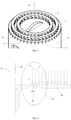
- figure 5 shows a preferred hook (shape) 7 with a hook foot 8 and a hook head 9, namely two side views of the hook (shape) 7.
- the hook foot 8 has a circular cross-section
- the hook head 9 has an essentially circular cross-section in the form of a segment of a circle.
- the left hook shape it can be seen that a part of the hook foot 8 formed by the first half shape extends beyond the point at which the curvature of the hook head 9 begins.
- figure 6 shows an example of a hook (shape) 7 with a double hook head 17.
- figure 7 12 shows a preferred embodiment of the hook and loop fastener connection part 18 in the form of a fastening device for a motor vehicle floor mat, namely its upper side which has a plurality of hooks 7 on the base plate 16.
- the hooks 7 are arranged in a circular concentric manner, with the orientation of the hook head shapes being opposite from one concentric ring of hooks 7 to the adjacent concentric ring of hooks 7, ie the hooks are arranged in a circular manner against one another.
- figure 8 shows the bottom of the in figure 7 shown hook and loop fastener connecting part 18, which has a fastener 19 in T-shaped anchoring element.
Abstract
Ein Hakenklettverschluss-Verbindungsteil ist mit einer Vielzahl von Haken (7) versehen, welche auf einer Grundplatte (16) angeordnet sind. Die Haken (7) weisen einen Hakenfuß (8) und einen Hakenkopf (9) auf. Hakenfuß (8) und Hakenkopf (9) sind innerhalb einer Ebene (10) angeordnet. Die Ebene (10) und die Grundplatte (16) sind in einem Winkel (ß) größer 90° zueinander angewinkelt.A hook and loop fastener connecting part is provided with a plurality of hooks (7) which are arranged on a base plate (16). The hooks (7) have a hook foot (8) and a hook head (9). Hook foot (8) and hook head (9) are arranged within a plane (10). The plane (10) and the base plate (16) are angled at an angle (ß) greater than 90° to one another.
Description
Die Erfindung betrifft eine Vorrichtung zur Herstellung eines Hakenklettverschluss-Verbindungsteils mittels eines Spritzgießverfahrens, ein Spritzgussverfahren zum Herstellen eines Hakenklettverschluss-Verbindungsteils, und ein Hakenklettverschluss-Verbindungsteil.The invention relates to a device for producing a hook and loop fastener connecting part by means of an injection molding process, an injection molding method for producing a hook and loop fastener connecting part, and a hook and loop fastener connecting part.
Bei einem Klettverschluss wird ein Hakenklettverschluss-Verbindungsteil, welches eine Vielzahl von Kletthaken aufweist, mit einem Schlaufenelement bzw. Flauschteil, welches Schlaufen bzw. Fasern aufweist, kontaktiert, wodurch sich die Kletthaken in den Schlaufen bzw. Fasern verhaken. Dadurch entsteht eine reversibel lösbare Verbindung zwischen Hakenklettverschluss-Verbindungsteil und Schlaufenelement.In the case of a Velcro fastener, a hook and loop fastener connection part, which has a large number of Velcro hooks, is contacted with a loop element or fleece part, which has loops or fibers, as a result of which the Velcro hooks hook into the loops or fibers. This creates a reversibly detachable connection between the hook and loop fastener connecting part and the loop element.
Diese Verbindung kann durch Abziehen des Schlaufenelements vom Hakenklettverschluss-Verbindungsteil wieder gelöst werden. Diese reversibel lösbare Verbindung kommt auf vielen Gebieten für ein wieder lösbares Befestigen von Gegenständen oder Bauteilen zum Einsatz. Beispielsweise werden bei Kraftfahrzeugen Bodenmatten am Fahrzeugboden gegen Verrutschen oder Abheben mittels einer Klettverschlussverbindung gesichert, indem am Boden des Innenraums des Fahrzeugs Befestigungsmittel verankert werden, welche ein Hakenklettverschluss-Verbindungsteil aufweisen, das beim Kontaktieren eines Flauschteils einer Fußmatte eine reversible Befestigung der Fußmatte am Fahrzeugboden ermöglicht.This connection can be released again by pulling the loop element off the hook and loop fastener connection part. This reversibly detachable connection is used in many areas for releasably attaching objects or components. For example, floor mats on the vehicle floor are secured against slipping or lifting by means of a Velcro connection in motor vehicles by fastening means being anchored to the floor of the interior of the vehicle, which have a hook and loop fastener connection part that when contacting a Velcro part of a floor mat allows a reversible attachment of the floor mat to the vehicle floor.
Eine Klettverschlussverbindung in Form einer Befestigungsvorrichtung für eine Kraftfahrzeug-Fußmatte wird herkömmlicherweise dadurch bereitgestellt, dass ein Grundkörper mit einer Vielzahl von Kletthaken mittels chemischer oder thermischer Klebeverbindungen, beispielsweise mit lösungsmittelhaltigen Klebstoffen oder Heißkleber, auf ein beispielsweise kreisförmiges Trägerteil aufgeklebt wird, und dieser Trägerteil wird am Boden des Fahrzeuginnenraums mit einem Befestigungsmittel befestigt. Abgesehen von der Umweltbelastung durch lösungsmittelhaltige Substanzen sind weder die chemischen noch die thermischen Klebeverbindungen zufriedenstellend. Denn es besteht die Gefahr, dass sich der Grundkörper mit der Vielzahl von Kletthaken vom Trägerteil löst, wenn die Temperatur und/oder die relative Luftfeuchtigkeit im Fahrzeug zu hoch sind. Ferner besteht die Gefahr der Ablösung auch, wenn die Fußmatte länger im Gebrauch war, und sich der Grundkörper mit der Vielzahl von Kletthaken durch mechanische Beanspruchung, wie z.B. Fußbewegungen der im Fahrzeug befindlichen Personen, vom Trägerteil löst.A hook-and-loop fastener connection in the form of a fastening device for a motor vehicle floor mat is conventionally provided in that a base body with a large number of hook-and-loop hooks is glued to a support part that is circular, for example, by means of chemical or thermal adhesive connections, for example with solvent-based adhesives or hot-melt glue, and this support part is attached to the Floor of the vehicle interior fastened with a fastener. Apart from the environmental impact of solvent-based substances, neither the chemical nor the thermal adhesive bonds are satisfactory. This is because there is a risk that the base body with the large number of Velcro hooks will become detached from the carrier part if the temperature and/or the relative humidity in the vehicle are too high. There is also a risk of detachment if the floor mat has been in use for a long time and the base body with the large number of Velcro hooks detaches from the carrier part as a result of mechanical stress, such as foot movements by the people in the vehicle.
Im Stand der Technik sind auch Alternativen zum oben beschriebenen herkömmlichen Aufkleben des Grundkörpers mit Vielzahl von Kletthaken auf ein Trägerteil bekannt.Alternatives to the above-described conventional gluing of the base body with a large number of Velcro hooks onto a carrier part are also known in the prior art.
Aufgabe der vorliegenden Erfindung ist es, eine Vorrichtung, ein Verfahren sowie ein Hakenklettverschluss-Verbindungsteil bereitzustellen, welche ein leichtes Entfernen bzw. Auswerfen der Haken eines spritzgegossenen Hakenklettverschluss-Verbindungsteils innerhalb einer Spritzgussform ermöglicht. Ferner ist es die Aufgabe der vorliegenden Erfindung, ein Hakenklettverschluss-Verbindungsteil bereitzustellen, welches eine besonders stabile Klettverschlussverbindung mit einem Flauschteil gewährleistet.It is the object of the present invention to provide a device, a method and a hook and loop fastener connection part which enables the hooks of an injection-molded hook and loop fastener connection part to be easily removed or ejected within an injection mold. Furthermore, it is the object of the present invention to provide a hook and loop fastener connection part which ensures a particularly stable hook and loop fastener connection with a fleece part.
Diese Aufgabe wird gelöst durch ein Hakenklettverschluss-Verbindungsteil gemäß Anspruch 1.This object is achieved by a hook and loop fastener fastener according to
Insbesondere wird diese Aufgabe gelöst durch eine Vorrichtung zur Herstellung eines Hakenklettverschluss-Verbindungsteils mittels eines Spritzgießverfahrens, umfassend:
Eine Spritzgussform mit einer Vielzahl von ersten und zweiten Halbformen, wobei jede erste Halbform eine Vielzahl von ersten Hohlräumen in einer ersten Oberfläche und jede zweite Halbform eine Vielzahl von zweiten Hohlräumen in einer zweiten Oberfläche aufweist, und erste und zweite Oberflächen sich gegenüberliegen und kontaktieren, so dass der erste und zweite Hohlraum gemeinsam einen Gesamthohlraum in Hakenform bilden,
wobei die Hakenform einen Hakenfuß und einen Hakenkopf aufweist, und Hakenfuß und Hakenkopf innerhalb einer Ebene angeordnet sind, wobei der Hakenfuß mindestens durch den ersten Hohlraum gebildet wird und der Hakenkopf mindestens durch den zweiten Hohlraum gebildet wird,
wobei die Spritzgussform eine Längsachse aufweist, entlang der die zweiten Halbformen gegenüber den ersten Halbformen verschiebbar sind,
dadurch gekennzeichnet, dass die Ebene und die Längsachse zueinander angewinkelt sind.In particular, this object is achieved by a device for producing a hook and loop fastener connecting part by means of an injection molding process, comprising:
An injection mold having a plurality of first and second half molds, each first half mold having a plurality of first cavities in a first surface and each second half mold having a plurality of second cavities in a second surface, and first and second surfaces facing and contacting so that the first and second cavity together form an overall cavity in the shape of a hook,
wherein the hook shape has a hook base and a hook head, and the hook base and hook head are arranged within one plane, the hook base being formed at least by the first cavity and the hook head being formed at least by the second cavity,
wherein the injection mold has a longitudinal axis along which the second half molds can be displaced relative to the first half molds,
characterized in that the plane and the longitudinal axis are angled towards each other.
Die der Erfindung zu Grunde liegende Idee besteht darin, dass die ersten und zweiten Halbformen so gebildet sind, dass die Ebene, innerhalb welcher der Hakenfuß und der Hakenkopf der Hakenform angeordnet sind, und die Längsachse der Spritzgussform zueinander angewinkelt sind. Dies ermöglicht zum einen, dass ein in der Spritzgussform spritzgegossener Haken leicht durch Verschieben der zweiten Halbformen gegenüber der ersten Halbformen entlang der Längsachse der Spritzgussform aus den ersten und zweiten Halbformen entfernt bzw. ausgeworfen werden kann, und ermöglicht die Bereitstellung einer vorteilhaften Dimensionierung des Hakenkopfes sowie einer vorteilhaften angewinkelten Anordnung der spritzgegossenen Haken auf dem Hakenklettverschluss-Verbindungsteil.The idea on which the invention is based is that the first and second half-moulds are formed in such a way that the plane within which the Hook foot and the hook head of the hook shape are arranged, and the longitudinal axis of the injection mold are angled to each other. On the one hand, this makes it possible for a hook that has been injection-molded in the injection mold to be easily removed or ejected from the first and second half-molds by moving the second half-molds relative to the first half-molds along the longitudinal axis of the injection mold, and makes it possible to provide an advantageous dimensioning of the hook head as well an advantageous angled arrangement of the injection molded hooks on the hook and loop fastener connection part.
Nachfolgend werden die Begriffe "Hakenform" bzw. "Haken", "Halbform" "Oberfläche" meist im Singular verwendet, wobei damit exemplarisch einer bzw. eine der Vielzahl von "Haken(formen)", "Halbformen" oder "Oberflächen" der erfindungsgemäßen Vorrichtung gemeint sind.In the following, the terms "hook shape" or "hook", "half-shape" "surface" are mostly used in the singular, with one or one of the large number of "hook (shapes)", "half-shapes" or "surfaces" of the invention being used as an example device are meant.
Unter dem hier verwendeten Begriff "Hakenklettverschluss-Verbindungsteil" ist ein eine Vielzahl von Haken aufweisender Gegenstand zu verstehen, dessen Haken mit einem Schlaufenelement bzw. Flauschteil, welches Schlaufen bzw. Fasern aufweist, beim Kontaktieren verhaken. Dadurch entsteht eine reversibel lösbare Verbindung zwischen Hakenklettverschluss-Verbindungsteil und Schlaufenelement.The term "hook and loop fastener connecting part" used here means an object having a large number of hooks, the hooks of which hook onto a loop element or looped part which has loops or fibers when it comes into contact. This creates a reversibly detachable connection between the hook and loop fastener connecting part and the loop element.
Unter dem hier verwendeten Begriff "Hakenkopf" ist eine Struktur zu verstehen, welche ein Verhaken mit einer filz- oder faserartigen Struktur eines Schlaufenelements bzw. Flauschteils ermöglicht. Eine solche Struktur kann eine gebogene bzw. runde Struktur, zum Beispiel eine halbkreisförmige Struktur oder eine Struktur, welche weniger als einen Halbkreis darstellt, z.B. 1/3 Kreis, oder mehr als einen Halbkreis darstellt, z.B. einen 5/8 Kreis, sein. Alternativ kann diese Struktur auch eine winkelige bzw. eckige Form aufweisen, wie zum Beispiel eine umgekehrte V-, oder eine eckige, umgekehrte U-Form. Auch Mischformen der vorgenannten Strukturen sind möglich, z.B. umgekehrte V- oder U-Formen mit kreisförmig abgerundeten Ecken, oder gebogene bzw. runde Strukturen, welche durch geradlinige Elemente ergänzt sind, wie z.B. eine abgerundete, umgekehrte U-Form. Bevorzugt hat der Hakenkopf eine 1/3 bis 5/8 Kreisform. Die Hakenformen können auch als Doppelhaken ausgebildet sein, welche man erhält, indem man zwei Hakenköpfe an einem Hakenfuß bildet, und diese Hakenfüße in 180° entgegengesetzte Richtungen zeigen.The term "hook head" used here is to be understood as meaning a structure which enables hooking with a felt or fibrous structure of a loop element or fleece part. Such a structure can be a curved structure, for example a semicircular structure or a structure which is less than a semicircle,
Unter dem hier verwendeten Begriff "Hakenfuß" ist eine Struktur zu verstehen, welche den "Hakenkopf" mit einem Grundkörper, z.B. einer Grundplatte, des Hakenklettverschluss-Verbindungsteils verbindet. Bevorzugt weist der "Hakenfuß" eine geradlinige Struktur auf. Bei einem kreisförmig gekrümmten Hakenkopf beginnt der Hakenkopf dort, wo die Krümmung des Hakenkopfs beginnt. Bei einer winkeligen bzw. eckigen Form des Hakenkopfs endet der Hakenfuß und beginnt der Hakenkopf an einem Punkt, wo eine imaginäre Linie, welche vom Ende des Hakenkopfes ausgeht, den Hakenfuß als Senkrechte schneidet. Allerdings ist die Trennung zwischen Hakenkopf und Hakenfuß mittels des vorbeschriebenen Punktes rein schematisch. Denn bei einer dreidimensionalen Ausgestaltung kann ein Teil des Hakenfußes diesen schematischen Trennpunkt entlang der Längsrichtung des Hakenfußes höhenmäßig unter- oder überschreiten, z.B. wenn der Hakenkopf im zweiten Hohlraum der zweiten Halbform gebildet wird, und der Hakenfuß im ersten Hohlraum der ersten Halbform und im zweiten Hohlraum der zweiten Halbform gebildet ist.As used herein, the term "hook foot" means a structure that connects the "hook head" to a body, such as a base plate, of the hook and loop fastener fastener. The "hook foot" preferably has a rectilinear structure. With a circularly curved hook head, the hook head begins where the curvature of the hook head begins. With an angular shape of the hook head, the hook foot ends and the hook head begins at a point where an imaginary line emanating from the end of the hook head intersects the hook foot as a perpendicular. However, the separation between hook head and hook foot by means of the point described above is purely schematic. In the case of a three-dimensional design, part of the hook foot can fall below or exceed this schematic separation point along the longitudinal direction of the hook foot, e.g. if the hook head is formed in the second cavity of the second half mold and the hook foot is formed in the first cavity of the first half mold and in the second cavity the second half mold is formed.
Unter dem hier verwendeten Begriff "Längsachse" der Spritzgussform ist eine Achse zu verstehen, entlang der die zweiten Halbformen gegenüber den ersten Halbformen verschiebbar sind. Das heißt, die Verschiebung der ersten und zweiten Halbformen kann auf oder parallel zur Längsachse der Spritzgussform erfolgen. Vorzugsweise steht die Längsachse der Spritzgussform senkrecht zu einer Fläche der Spritzgussform, welche die Seite einer Grundplatte des Hakenklettverschluss-Verbindungsteils formt, auf der die Vielzahl von Haken gebildet werden, wobei diese Fläche vorzugsweise ganz oder teilweise durch die weiter unten beschriebenen dritten Oberflächen der ersten Halbformen und vierten Oberflächen der zweiten Halbformen gebildet wird.The term "longitudinal axis" of the injection mold used here is to be understood as meaning an axis along which the second half-molds can be displaced relative to the first half-molds. This means that the displacement of the first and second half molds can take place on or parallel to the longitudinal axis of the injection mold. Preferably, the longitudinal axis of the injection mold is perpendicular to a surface of the injection mold that forms the face of a base plate of the hook and loop fastener fastener on which the plurality of hooks are formed, which surface is preferably wholly or partially defined by the third surfaces of the first half molds described below and fourth surfaces of the second half molds.
Neben der speziellen Spritzgussform, die mit ersten und zweiten Halbformen ausgestaltet ist, weist die Vorrichtung die üblichen Mittel einer Spritzgussvorrichtung auf, wie z.B. Mittel zum Aufheizen des in die Spritzgussform einzuspritzenden Kunststoff, Anspritzkanäle für die Spritzgussform, um geschmolzenen Kunststoff in die Spritzgussform zu pressen, und Mittel zum geeigneten Öffnen bzw. Schließen der Spritzgussform.In addition to the special injection mold, which is designed with first and second half molds, the device has the usual means of an injection molding device, such as means for heating the plastic to be injected into the injection mold, injection channels for the injection mold to press molten plastic into the injection mold, and means for appropriately opening and closing the injection mold.
Die Ebene, innerhalb welcher der Hakenfuß und der Hakenkopf der Hakenform angeordnet sind, und die Längsachse der Spritzgussform sind vorzugsweise mit einem Winkel von bis zu 40° zueinander angewinkelt, weiter bevorzugt 5° bis 30°, und besonders bevorzugt 10° bis 20°. Diese bevorzugte Anwinkelung von Ebene und Längsachse ist vorteilhaft, weil hierdurch ermöglicht wird, die spritzgegossenen Haken leichter aus den ersten und zweiten Hohlräumen zu entfernen bzw. auszuwerfen, und bei Bedarf kann dank dieser Winkelwahl der Hakenkopf der Hakenform vollständig in dem zweiten Hohlraum gebildet werden. Die im Zusammenhang mit der angewinkelten Anordnung von der Ebene und der Längsachse zueinander angegebenen Winkel α schließen auch negative Winkel ein, das heißt -40° zueinander angewinkelt, weiter bevorzugt -5° bis -30°, und besonders bevorzugt -10° bis -20°. Das heißt, innerhalb der ersten und zweiten Halbformen können die Hakenformen gegenläufig gebildet sein, also einmal mit positivem Winkel und einmal mit negativem Winkel.The plane within which the hook foot and the hook head of the hook mold are arranged and the longitudinal axis of the injection mold are preferably angled to one another at an angle of up to 40°, more preferably 5° to 30°, and particularly preferably 10° to 20°. This preferred angling of plane and longitudinal axis is advantageous because it allows the injection-molded hook easier to remove or eject from the first and second cavities, and if necessary, thanks to this choice of angles, the hook head of the hook shape can be formed entirely in the second cavity. The angles α given in connection with the angled arrangement of the plane and the longitudinal axis to one another also include negative angles, ie angled at -40° to one another, more preferably -5° to -30°, and particularly preferably -10° to -20 °. This means that the hook shapes can be formed in opposite directions within the first and second half shapes, ie once with a positive angle and once with a negative angle.
Es ist bevorzugt, dass die ersten und zweiten Oberflächen der Vielzahl von ersten und zweiten Halbformen parallel zueinander angeordnet sind, weiter bevorzugt parallel zur Längsachse. Diese parallele Anordnung ermöglicht es, dass die ersten und zweiten Halbformen jeweils gleichartig gestaltet werden können, d.h. die Ausgestaltung bzw. Herstellung der ersten und zweiten Halbformen ist einfacher im Vergleich zu einer nicht-parallelen Anordnung. Besonders vorteilhaft ist es, wenn die ersten und zweiten Oberflächen der Vielzahl von ersten und zweiten Halbformen parallel zur Längsachse zueinander angeordnet sind. Dies ermöglicht es, dass sowohl die ersten als auch die zweiten Halbformen entlang der Längsachse gegeneinander beliebig nach unten oder oben verschiebbar sind.It is preferred that the first and second surfaces of the plurality of first and second half molds are arranged parallel to each other, more preferably parallel to the longitudinal axis. This parallel arrangement enables the first and second half molds to be designed in the same way, i.e. the design or manufacture of the first and second half molds is simpler compared to a non-parallel arrangement. It is particularly advantageous if the first and second surfaces of the plurality of first and second half molds are arranged parallel to one another in relation to the longitudinal axis. This makes it possible for both the first and the second half-moulds to be displaced upwards or downwards as desired along the longitudinal axis.
Vorzugsweise wird der Hakenfuß durch den ersten und zweiten Hohlraum gebildet, und der Hakenkopf wird durch den zweiten Hohlraum gebildet. Dies hat den Vorteil, dass mittels Verschieben der zweiten Halbform gegenüber der ersten Halbform der spritzgegossene Haken leicht entfernt bzw. entformt werden kann, da der Hakenkopf komplett im zweiten Hohlraum ausgebildet ist, d.h. es kann durch Verschieben z.B. auf den Hakenkopf gedrückt werden, um den spritzgegossenen Haken leicht zu entfernen bzw. entformen. Ferner ist es bei dieser Ausführungsform vorteilhaft, dass dadurch, dass der Hakenkopf nur in dem zweiten Hohlraum gebildet ist, der Hakenkopf des spritzgegossenen Hakens das Verschieben der ersten und zweiten Halbform gegeneinander nicht blockieren kann.Preferably, the hook foot is formed by the first and second cavities and the hook head is formed by the second cavity. This has the advantage that the injection-molded hook can be easily removed or demoulded by moving the second half-mould relative to the first half-mould, since the hook head is formed completely in the second cavity, i.e. it can be pressed on the hook head by moving it, for example, in order to injection molded hook easy to remove or demould. Furthermore, it is advantageous in this embodiment that because the hook head is only formed in the second cavity, the hook head of the injection-molded hook cannot block the displacement of the first and second half molds relative to one another.
Der Hakenkopf weist bevorzugt einen Querschnitt bzw. eine Querschnittsfläche gleich oder größer als der Querschnitt bzw. die Querschnittfläche des Hakenfußes auf. Dies hat den Vorteil, dass mittels der erfindungsgemäßen Vorrichtung spritzgegossene Kletthaken bereitgestellt werden können, welche besonders stabil sind, da die Dimensionierung des Hakenkopfs einen wichtigen Einfluss auf die Stabilität der Klettverbindung des Hakenklettverschluss-Verbindungsteils mit einem Flauschteil hat. Denn wenn der Hakenkopf vom Querschnitt bzw. der Querschnittsfläche her geringer dimensioniert ist als der Hakenfuß, besteht die Gefahr, dass beim Ziehen am Flauschteil die Hakenköpfe der Kletthaken des Hakenklettverschluss-Verbindungsteils zumindest teilweise abreißen, wodurch die Klettverbindung geschwächt wird.The hook head preferably has a cross section or a cross-sectional area equal to or larger than the cross section or the cross-sectional area of the hook foot. This has the advantage that the device according to the invention can be used to provide injection-molded Velcro hooks which are particularly stable, since the dimensions of the hook head have an important influence on the stability of the Velcro connection of the hook and loop fastener connecting part has a fleece part. Because if the cross-section or cross-sectional area of the hook head is smaller than the hook foot, there is a risk that the hook heads of the hook and loop fasteners of the hook and loop fastener connection part will at least partially tear off when the looped part is pulled, thereby weakening the hook and loop connection.
Unter dem hier verwendeten Begriff "Spritzgussform" ist ein Gesamthohlraum in Form eines Hakenklettverschluss-Verbindungsteils zu verstehen, wobei die Vielzahl von ersten und zweiten Halbformen die Vielzahl von Haken des Hakenklettverschluss-Verbindungsteils sowie die Oberfläche eines Grundkörpers bilden, wenn die Spritzgussform mit geschmolzenem Kunststoff ausgespritzt wird. Die Spritzgussform weist einen oder mehrere Anspritzkanäle auf, welche ein Ausspritzen der Spritzgussform mit geschmolzenem Kunststoff ermöglicht bzw. ermöglichen. Der Grundkörper des Hakenklettverschluss-Verbindungsteils kann prinzipiell eine beliebige Form aufweisen, bevorzugt ist der Grundkörper in Form einer Grundplatte gebildet, d.h. einem planaren Körper mit einer gewissen Dicke, auf welchem die Vielzahl von Haken gebildet werden. Optional kann der Grundkörper Befestigungsmittel aufweisen, die eine Befestigung des Grundkörpers mit der Vielzahl von Haken an einem weiteren Gegenstand erlaubt. Somit kann die "Spritzgussform" einen Gesamthohlraum darstellen, welcher neben der durch die Vielzahl von ersten und zweiten Halbformen gebildeten Vielzahl von Haken und der Oberfläche des Grundkörpers, auf welcher die Vielzahl der Haken gebildet ist, auch die weitere Form des Grundkörpers mit optionalem Befestigungsmittel abbildet, so dass ein Hakenklettverschluss-Verbindungsteil mit Vielzahl von Haken und Grundkörper mit optionalem Befestigungsmittel in der Spritzgussform einstückig gebildet werden kann.The term "injection mold" as used herein means an overall cavity in the form of a hook and loop fastener connecting part, the plurality of first and second half molds forming the plurality of hooks of the hook and loop fastener connecting part and the surface of a base body when the injection mold is ejected with molten plastic will. The injection mold has one or more injection channels, which enable or enable the injection mold to be ejected with molten plastic. The main body of the hook and loop fastener connecting part can in principle have any shape, preferably the main body is formed in the form of a base plate, i.e. a planar body with a certain thickness on which the plurality of hooks are formed. Optionally, the base body can have fastening means that allow the base body to be fastened with the plurality of hooks to a further object. The "injection mold" can thus represent an overall cavity which, in addition to the plurality of hooks formed by the plurality of first and second half molds and the surface of the base body on which the plurality of hooks is formed, also depicts the further shape of the base body with optional fastening means , so that a hook and loop fastener connecting part with a plurality of hooks and base body with optional fastening means can be integrally formed in the injection mold.
Die Spritzgussform der erfindungsgemäßen Vorrichtung ist vorzugsweise so gestaltet, dass die erste Halbform eine dritte Oberfläche und die zweite Halbform eine vierte Oberfläche aufweisen, und die dritte Oberfläche an die erste Oberfläche angrenzt und die vierte Oberfläche an die zweite Oberfläche angrenzt, wobei die dritte und vierte Oberfläche gemeinsam eine Öffnung bilden, die den Querschnitt des unteren Endes des Hakenfußes darstellt. Bevorzugt mündet diese Öffnung in einen weiteren Hohlraum in Form einer Grundplatte des Hakenklettverschluss-Verbindungsteils, so dass beim Ausspritzen der Spritzgussform ein Hakenklettverschluss-Verbindungsteil mit einer Vielzahl von auf der Grundplatte gebildeten Haken erhalten wird. Diese Ausgestaltung der Spritzgussform ist vorteilhaft, um ein Hakenklettverschluss-Verbindungsteil mit einer Grundplatte, auf welcher eine Vielzahl von Kletthaken gebildet sind, bereitzustellen.The injection mold of the device according to the invention is preferably designed in such a way that the first half mold has a third surface and the second half mold has a fourth surface, and the third surface is adjacent to the first surface and the fourth surface is adjacent to the second surface, with the third and fourth Surface together form an opening that represents the cross section of the lower end of the hook base. This opening preferably opens into a further cavity in the form of a base plate of the hook and loop fastener connection part, so that when the injection mold is ejected, a hook and loop fastener connection part with a large number of hooks formed on the base plate is obtained. This configuration of the injection mold is advantageous for using a hook and loop fastener connection part a base plate on which a plurality of Velcro hooks are formed.
Der weitere Hohlraum in Form einer Grundplatte des Hakenklettverschluss-Verbindungsteils kann auf einer Seite, die den dritten und vierten Oberflächen gegenüberliegt, ferner einen Hohlraum aufweisen, welcher die Form eines Befestigungsmittels aufweist, so dass beim Ausspritzen der Spritzgussform ein Hakenklettverschluss-Verbindungsteil mit einer Vielzahl von auf der Grundplatte gebildeten Haken erhalten wird, wobei die Grundplatte auf der die Vielzahl von Haken aufweisenden Seite gegenüberliegenden Seite ein Befestigungsmittel gebildet wird.The further cavity in the form of a base plate of the hook and loop fastener connection part can also have a cavity on a side opposite the third and fourth surfaces, which has the shape of a fastener, so that when the injection mold is ejected, a hook and loop fastener connection part with a plurality of hooks formed on the base plate, wherein the base plate is formed with a fastener on the side opposite to the side having the plurality of hooks.
Es ist bevorzugt, dass die dritte Oberfläche rechtwinklig zur ersten Oberfläche und die vierte Oberfläche rechtwinklig zur zweiten Oberfläche ist. Dies ermöglicht ein vorteilhaft einfache Verschiebbarkeit der ersten und zweiten Halbformen gegeneinander, und somit auch ein vorteilhaftes Entfernen bzw. Auswerfen aus der Spritzgussform.It is preferred that the third surface is perpendicular to the first surface and the fourth surface is perpendicular to the second surface. This enables the first and second half molds to be displaced in an advantageously simple manner in relation to one another, and thus also advantageously allows them to be removed or ejected from the injection mold.
Die zweiten Halbformen sind vorzugsweise in Richtung des weiteren Hohlraums in Form einer Grundplatte des Hakenklettverschluss-Verbindungsteils verschiebbar, während die ersten Halbformen ihre Position beibehalten. Dies ermöglicht ein besonders vorteilhaftes Entfernen bzw. Entformen. Denn wird der weitere Hohlraum in Form einer Grundplatte auf der Seite, welche den ersten und zweiten Hakenformen gegenüberliegt, geöffnet, so kann durch die vorgenannte Verschiebung mittels der zweiten Halbformen Druck auf die spritzgegossenen Hakenköpfe und die spritzgegossene Grundplatte ausgeübt werden, wodurch der Hakenfuß des spritzgegossenen Hakens aus dem ersten Hohlraum herausgedrückt wird.The second half molds are preferably displaceable towards the further cavity in the form of a base plate of the hook and loop fastener connecting part, while the first half molds maintain their position. This enables a particularly advantageous removal or demoulding. Because if the additional cavity in the form of a base plate is opened on the side opposite the first and second hook molds, pressure can be exerted on the injection-molded hook heads and the injection-molded base plate by means of the aforementioned displacement by means of the second half-molds, whereby the hook base of the injection-molded Hook is pushed out of the first cavity.
In der erfindungsgemäßen Vorrichtung weist bevorzugt mindestens eine erste Halbform auf zwei sich gegenüberliegenden Seiten jeweils eine erste Oberfläche auf, und mindestens eine zweite Halbform weist auf zwei sich gegenüberliegenden Seiten jeweils eine zweite Oberfläche auf. Diese Ausgestaltung ermöglicht es, dass mit der erfindungsgemäßen Vorrichtung ein Hakenklettverschluss-Verbindungsteil mit einer hohen Dichte an Haken bereitgestellt werden kann.In the device according to the invention, at least one first half mold preferably has a first surface on each of two opposite sides, and at least one second half mold has a second surface on each of two opposite sides. This configuration makes it possible for a hook and loop fastener connection part with a high density of hooks to be provided with the device according to the invention.
Die dritten und vierten Oberflächen sind vorzugsweise planar. Dies ermöglicht die Herstellung eines Hakenklettverschlussteils mit planarer Grundplatte.The third and fourth surfaces are preferably planar. This enables the production of a hook and loop fastener part with a planar base plate.
Die ersten und zweiten Oberflächen sind vorzugsweise planar. Dadurch wird eine einfache Gestaltung und Herstellung der ersten und zweiten Halbformen ermöglicht, und eine leichte Verschiebbarkeit der ersten und zweiten Halbformen gegeneinander ermöglicht.The first and second surfaces are preferably planar. This enables a simple design and manufacture of the first and second half molds and enables the first and second half molds to be easily displaced relative to one another.
Es ist bevorzugt, dass die zweiten Hohlräume so gebildet sind, dass die Enden der Hakenkopfformen jeweils die gleiche Orientierung aufweisen.It is preferred that the second cavities are formed so that the ends of the hook head shapes have the same orientation, respectively.
Die ersten und zweiten Halbformen sind vorzugsweise konzentrisch zueinander angeordnet, weiter bevorzugt sind sie kreisförmig konzentrisch zueinander angeordnet. Eine solche konzentrische Anordnung hat den Vorteil, dass beim Entfernen bzw. Auswerfen durch Verschieben der konzentrischen ersten und zweiten Halbformen gegeneinander eine relativ gleichmäßige Kräfteverteilung beim Drücken auf die spritzgegossenen Hakenköpfe bzw. die spritzgegossene Grundplatte gegeben ist.The first and second half molds are preferably arranged concentrically with one another, more preferably they are arranged concentrically with one another in a circle. Such a concentric arrangement has the advantage that when removing or ejecting by moving the concentric first and second half molds relative to one another, there is a relatively even distribution of forces when pressing on the injection-molded hook heads or the injection-molded base plate.
Wenn die ersten und zweiten Halbformen kreisförmig konzentrisch zueinander angeordnet sind, so ist es bevorzugt, dass alle zweiten Hohlräume so gebildet sind, dass alle Hakenkopfformen im Wesentlichen tangential zur Kreisform der zweiten Halbform gebildet sind und die Enden der Hakenkopfformen jeweils die gleiche Orientierung aufweisen. "Im Wesentlichen tangential" bedeutet in diesem Kontext, dass die Ebene, innerhalb welcher Hakenfuß und Hakenkopf angeordnet sind, senkrecht bzw. mit einer Toleranz von ± 5° auf einem Berührungsradius der zweiten Halbform steht. Diese jeweils gleiche Orientierung kann, wenn eine erste Halbform auf zwei sich gegenüberliegenden Seiten jeweils eine erste Oberfläche aufweist und eine zweite Halbform auf zwei sich gegenüberliegenden Seiten jeweils eine zweite Oberfläche aufweist, entweder auf beiden gegenüberliegenden Seiten gleich oder entgegengesetzt sein, bevorzugt ist sie entgegengesetzt. Weisen die gegenüberliegenden Seiten von erster Halbform und zweiter Halbform jeweils entgegengesetzte Orientierungen bezüglich der Hakenformen auf, so erhält man mittels der erfindungsgemäßen Vorrichtung ein Hakenklettverschluss-Verbindungsteil, in welchem die Vielzahl der kreisförmig konzentrisch angeordneten Haken in einem Kreis die Enden der Hakenköpfe tangential zur Kreisform die gleiche Orientierung aufweisen, während in einem zu diesem Kreis von Haken benachbarten Kreis die Enden der Hakenköpfe tangential zur Kreisform eine Orientierung aufweisen, welche der des benachbarten Kreises entgegengesetzt ist. Diese kreisförmig konzentrische Anordnung der Haken, in welcher die Hakenköpfe der benachbarten Kreise jeweils eine entgegengesetzte tangentiale Orientierung zur Kreisform aufweisen, wird hier auch als "kreisförmig konzentrisch gegeneinander" bezeichnet. Diese Anordnung ermöglicht eine besonders vorteilhafte, stabile Klettverbindung mit einem Flauschteil.If the first and second half-moulds are arranged circularly concentrically to one another, it is preferred that all second cavities are formed in such a way that all hook head shapes are formed essentially tangentially to the circular shape of the second half-mould and the ends of the hook head shapes each have the same orientation. "Essentially tangential" in this context means that the plane within which the hook base and hook head are arranged is perpendicular or with a tolerance of ±5° on a contact radius of the second half-shape. If a first half-mold has a first surface on two opposite sides and a second half-mold has a second surface on two opposite sides, this respective orientation can be either the same or opposite on both opposite sides, preferably opposite. If the opposite sides of the first half-shape and second half-shape each have opposite orientations with regard to the hook shapes, a hook and loop fastener connection part is obtained by means of the device according to the invention, in which the plurality of hooks arranged concentrically in a circle form the ends of the hook heads tangentially to the circular shape have the same orientation, while in a circle adjacent to this circle of hooks the ends of the hook heads tangential to the circular shape have an orientation opposite to that of the adjacent circle. This circular concentric arrangement of hooks, in which the hook heads of adjacent circles each have an opposite tangential orientation to the circular shape, is also referred to herein as "circular concentrically against each other". This arrangement enables a particularly advantageous, stable Velcro connection with a fleece part.
Gemäß einer bevorzugten Ausführungsform ist die zweite Halbform so gebildet, dass der Hakenkopf als Doppelhakenkopf, dessen Hakenköpfe in 180° entgegengesetzte Richtungen zeigen, geformt wird. Dies hat den Vorteil, dass ein Kletthaken mit 2 Hakenköpfen gebildet werden kann, wodurch sich die Stabilität der Klettverbindung im Vergleich zu Haken mit nur einem Hakenkopf quasi verdoppelt.According to a preferred embodiment, the second half mold is formed in such a way that the hook head is formed as a double hook head, the hook heads of which point in 180° opposite directions. This has the advantage that a Velcro hook can be formed with 2 hook heads, which virtually doubles the stability of the Velcro connection compared to hooks with only one hook head.
Der Querschnitt bzw. die Querschnittsfläche von Hakenfuß und/oder Hakenkopf kann prinzipiell jede Form aufweisen, beispielsweise mehreckig, wie zum Beispiel dreieckig, viereckig, fünfeckig oder sechseckig, im Wesentlich kreisförmig, oder eine Mischform aus mehreckig und im Wesentlichen kreisförmig, z.B. ein mehreckiger Querschnitt, in welchem die Ecken abgerundet sind. Es ist bevorzugt, dass der Querschnitt bzw. die Querschnittsfläche von Hakenfuß und/oder Hakenkopf im Wesentlichen kreisförmig ist. "Im Wesentlichen kreisförmig" bedeutet hier kreisförmig, kreissegmentförmig oder oval, wobei es bevorzugt ist, dass der Querschnitt von Hakenfuß und/oder Hakenkopf kreisförmig oder kreissegmentförmig ist. Ein kreissegmentförmiger Querschnitt des Hakenkopfs kann beispielweise dadurch gebildet werden, dass der Kreisbogen des Kreissegments durch den zweiten Hohlraum der zweiten Halbform gebildet wird, und die Kreissehne des Kreissegments durch eine plane erste Oberfläche der ersten Halbform.The cross-section or the cross-sectional area of the hook base and/or hook head can in principle have any shape, for example polygonal, such as triangular, square, pentagonal or hexagonal, essentially circular, or a mixed form of polygonal and essentially circular, e.g. a polygonal cross-section , in which the corners are rounded. It is preferred that the cross-section or the cross-sectional area of the hook base and/or hook head is essentially circular. “Essentially circular” here means circular, in the shape of a segment of a circle or oval, it being preferred for the cross section of the hook foot and/or hook head to be circular or in the shape of a segment of a circle. A cross section of the hook head in the shape of a segment of a circle can be formed, for example, in that the arc of the circle segment is formed by the second cavity of the second half-mould, and the chord of the circle segment is formed by a flat first surface of the first half-mould.
Die durch die dritte und vierte Oberfläche gemeinsam gebildete Öffnung ist bevorzugt kreisförmig, und die dritte Oberfläche bildet ein Kreissegment mit 60-80% der Kreisformfläche der Öffnung, und die vierte Oberfläche bildet ein Kreissegment mit 20-40% der Kreisformfläche der Öffnung, mit der Maßgabe, dass die gesamte Kreisformfläche der Öffnung 100% beträgt. Diese vorteilhafte Ausgestaltung der dritten und vierten Oberflächen ermöglicht es, dass in der ersten Halbform ein größerer Teil des Querschnitts des Hakenfußes gebildet werden kann, während die zweite Halbform einen kleineren Teil des Querschnitts des Hakenfußes bildet.The opening formed jointly by the third and fourth surfaces is preferably circular, and the third surface forms a circular segment with 60-80% of the circular shape of the opening, and the fourth surface forms a circular segment with 20-40% of the circular shape of the opening with which Provided that the total circular area of the opening is 100%. This advantageous configuration of the third and fourth surfaces makes it possible for a larger part of the cross section of the hook foot to be formed in the first half mold, while the second half mold forms a smaller part of the cross section of the hook foot.
Die nachfolgend erläuterten Dimensionierungen der Hakenform sind so gewählt, dass ein spritzgegossener Haken leicht aus den ersten bzw. zweiten Halbformen entform- bzw. entfernbar ist, ohne beschädigt zu werden, z.B. durch Abreißen des Hakenkopfes. Ferner wird durch die nachfolgend erläuterten Dimensionierungen der Hakenform beim Spritzgießen ein Haken erhalten, welcher eine vorteilhaft stabile Klettverschlussverbindung mit einem Flauschteil gewährleistet.The dimensions of the hook shape explained below are selected in such a way that an injection-molded hook can be easily demolded or removed from the first or second half-molds without being damaged, for example by tearing off the hook head. Furthermore, due to the dimensions explained below the hook shape obtained during injection molding a hook, which ensures an advantageously stable Velcro connection with a fleece part.
Die erste und zweite Halbform, insbesondere der erste Hohlraum der ersten Halbform und der zweite Hohlraum der zweiten Halbform, sind bevorzugt so dimensioniert, dass der kreisförmige Querschnitt des Hakenfußes einen Durchmesser von 0,3 bis 0,8 mm aufweist, weiter bevorzugt 0,4 bis 0,7 mm, besonders bevorzugt 0,45 bis 0,6 mm.The first and second half-mould, in particular the first cavity of the first half-mould and the second cavity of the second half-mould, are preferably dimensioned such that the circular cross-section of the hook base has a diameter of 0.3 to 0.8 mm, more preferably 0.4 to 0.7 mm, particularly preferably 0.45 to 0.6 mm.
Des Weiteren ist es bevorzugt, dass die erste und zweite Halbform so dimensioniert sind, dass der Hakenkopf einen Durchmesser gleich oder größer als der Durchmesser des Hakenfußes aufweist, bevorzugt weist der Hakenkopf bis zu 25% mehr Durchmesser auf als der Hakenfuß, bevorzugt von 4% bis zu 22% mehr, noch weiter bevorzugt von 6 bis zu 18% mehr, besonders bevorzugt von 8 bis zu 12% mehr. Falls der Hakenkopf keinen kreisförmigen Querschnitt aufweist, sondern einen kreissegmentförmigen, so ist der Durchmesser des kreissegmentförmigen Querschnitts des Hakenkopfes so gewählt, dass der/die kreissegmentförmige Querschnitt bzw. Querschnittsfläche des Hakenkopfes mindestens gleich oder bevorzugt größer als der/die kreisförmige Querschnitt bzw. Querschnittsfläche des Hakenfußes ist.Furthermore, it is preferred that the first and second half mold are dimensioned in such a way that the hook head has a diameter equal to or larger than the diameter of the hook foot, preferably the hook head has up to 25% more diameter than the hook foot, preferably 4% up to 22% more, more preferably from 6 up to 18% more, most preferably from 8 up to 12% more. If the hook head does not have a circular cross-section but a segment-shaped one, the diameter of the cross-section shaped like a segment of a circle of the hook head is selected in such a way that the cross-section shaped like a segment of a circle or cross-sectional area of the hook head is at least equal to or preferably larger than the circular cross-section or cross-sectional area of the hook foot is.
Darüber hinaus ist es bevorzugt, dass die erste und zweite Halbform so dimensioniert sind, dass die Hakenform vom Hakenfuß bis zum Hakenkopf eine Höhe von 1,2 bis 4 mm aufweist, weiter bevorzugt 1,5 bis 3 mm, besonders bevorzugt 1,8 bis 2,5 mm. Diese Höhe vom Hakenfuß bis zum Hakenkopf wird senkrecht von den dritten und vierten Oberflächen bis zum höchsten Punkt des Hakenkopfes der Hakenform gemessen.In addition, it is preferred that the first and second half mold are dimensioned such that the hook mold has a height of 1.2 to 4 mm, more preferably 1.5 to 3 mm, particularly preferably 1.8 to 1.8 mm from the hook foot to the hook head 2.5mm This height from hook root to hook head is measured perpendicularly from the third and fourth surfaces to the highest point of the hook head of the hook shape.
Der weitere Hohlraum in Form einer Grundplatte des Hakenklettverschluss-Verbindungsteils ist vorzugsweise kreisförmig und weist einen Durchmesser von 5 bis 10 cm und eine Dicke von 1 bis 5 mm auf, weiter bevorzugt einen Durchmesser von 6 bis 8,5 cm und eine Dicke von 1,5 bis 4 mm, besonders bevorzugt einen Durchmesser von 6 bis 7,5 cm und eine Dicke von 2 bis 3 mm. Die hier angegebene Dicke der kreisförmigen Grundplatte versteht sich ohne das optionale Befestigungsmittel, welches sich auf der die Vielzahl von Haken aufweisenden Seite gegenüberliegenden Seite befinden kann.The further cavity in the form of a base plate of the hook and loop fastener connecting part is preferably circular and has a diameter of 5 to 10 cm and a thickness of 1 to 5 mm, more preferably a diameter of 6 to 8.5 cm and a thickness of 1, 5 to 4 mm, particularly preferably a diameter of 6 to 7.5 cm and a thickness of 2 to 3 mm. The thickness of the circular base given herein is exclusive of the optional fastener, which may be on the opposite side having the plurality of hooks.
Es ist bevorzugt, dass das Hakenklettverschluss-Verbindungsteil eine Befestigungsvorrichtung für eine Kraftfahrzeug-Fußmatte ist. Bevorzugte Ausgestaltungen einer Befestigungsvorrichtung für eine Kraftfahrzeug-Fußmatte werden in der Beschreibung des erfindungsgemäßen Hakenklettverschluss-Verbindungsteils erläutert.It is preferable that the hook and loop fastener connecting part is a fastening device for an automobile floor mat. preferred Configurations of a fastening device for a motor vehicle floor mat are explained in the description of the hook and loop fastener connecting part according to the invention.
Gemäß einer besonders bevorzugten Ausführungsform wird eine Vorrichtung zur Herstellung eines Hakenklettverschluss-Verbindungsteils mittels eines Spritzgießverfahrens bereitgestellt, welche Folgendes umfasst:
Eine Spritzgussform mit einer Vielzahl von ersten und zweiten Halbformen, wobei jede erste Halbform eine Vielzahl von ersten Hohlräumen in einer ersten Oberfläche und jede zweite Halbform eine Vielzahl von zweiten Hohlräumen in einer zweiten Oberfläche aufweist, und erste und zweite Oberflächen sich gegenüberliegen und kontaktieren, so dass der erste und zweite Hohlraum gemeinsam einen Gesamthohlraum in Hakenform bilden,
wobei die Hakenform einen Hakenfuß und einen Hakenkopf aufweist, und Hakenfuß und Hakenkopf innerhalb einer Ebene angeordnet sind, wobei der Hakenfuß durch den ersten und zweiten Hohlraum gebildet wird und der Hakenkopf durch den zweiten Hohlraum gebildet wird,
wobei die Spritzgussform eine Längsachse aufweist, entlang der die zweiten Halbformen gegenüber den ersten Halbformen verschiebbar sind,
wobei die ersten und zweiten Oberflächen der Vielzahl von ersten und zweiten Halbformen parallel zueinander und parallel zur Längsachse angeordnet sind,
dadurch gekennzeichnet, dass die Ebene und die Längsachse zueinander angewinkelt sind in einem Winkel α von 5° bis 30°, bevorzugt 10° bis 20°,
bevorzugt ist der zweite Hohlraum so dimensioniert, dass der Hakenkopf einen Querschnitt gleich oder größer als der Querschnitt des Hakenfußes aufweist, und
bevorzugt sind die ersten und zweiten Halbformen kreisförmig konzentrisch zueinander angeordnet. Die vorgenannten besonders bevorzugte Ausführungsform der erfindungsgemäßen Vorrichtung umfasst ferner optional:According to a particularly preferred embodiment, there is provided a device for producing a hook and loop fastener connecting part by means of an injection molding process, which comprises:
An injection mold having a plurality of first and second half molds, each first half mold having a plurality of first cavities in a first surface and each second half mold having a plurality of second cavities in a second surface, and first and second surfaces facing and contacting so that the first and second cavity together form an overall cavity in the shape of a hook,
wherein the hook shape has a hook base and a hook head, and the hook base and hook head are arranged within one plane, the hook base being formed by the first and second cavities and the hook head being formed by the second cavity,
wherein the injection mold has a longitudinal axis along which the second half molds can be displaced relative to the first half molds,
wherein the first and second surfaces of the plurality of first and second half molds are arranged parallel to each other and parallel to the longitudinal axis,
characterized in that the plane and the longitudinal axis are angled to one another at an angle α of 5° to 30°, preferably 10° to 20°,
the second cavity is preferably dimensioned in such a way that the head of the hook has a cross section equal to or larger than the cross section of the foot of the hook, and
the first and second half molds are preferably arranged in a circle concentrically with one another. The aforementioned particularly preferred embodiment of the device according to the invention also optionally includes:
Die erste Halbform weist eine dritte Oberfläche und die zweite Halbform eine vierte Oberfläche auf, und die dritte Oberfläche grenzt an die erste Oberfläche an, und die vierte Oberfläche grenzt an die zweite Oberfläche an, wobei die dritte und vierte Oberfläche gemeinsam eine Öffnung bilden, die den Querschnitt des unteren Endes des Hakenfußes darstellt, wobei diese Öffnung in einen weiteren Hohlraum in Form einer Grundplatte des Hakenklettverschluss-Verbindungsteils mündet, so dass beim Ausspritzen der Spritzgussform ein Hakenklettverschluss-Verbindungsteil mit einer Vielzahl von auf der Grundplatte gebildeten Haken erhalten wird,
wobei die dritte Oberfläche rechtwinklig zur ersten Oberfläche ist und die vierte Oberfläche rechtwinklig zur zweiten Oberfläche ist, und die dritten und vierten Oberflächen planar sind.The first half mold has a third surface and the second half mold has a fourth surface, and the third surface is adjacent to the first surface and the fourth surface is adjacent to the second surface, the third and fourth surfaces together forming an opening that represents the cross-section of the lower end of the hook foot, with this opening in another cavity in the form of a base plate of the hook and loop fastener connecting part, so that when the injection mold is ejected, a hook and loop fastener connecting part with a large number of hooks formed on the base plate is obtained,
wherein the third surface is perpendicular to the first surface and the fourth surface is perpendicular to the second surface, and the third and fourth surfaces are planar.
Des Weiteren betrifft die Erfindung ein Spritzgussverfahren zum Herstellen eines Hakenklettverschluss-Verbindungsteils unter Verwendung der erfindungsgemäßen Vorrichtung. Die Vorteile dieses Spritzgussverfahrens ergeben sich aus den bereits oben erläuterten Vorteilen der Vorrichtung.Furthermore, the invention relates to an injection molding method for producing a hook and loop fastener connecting part using the device according to the invention. The advantages of this injection molding process result from the advantages of the device already explained above.
Das erfindungsgemäße Spritzgussverfahren unterscheidet sich hinsichtlich Verfahrensparametern wie der Temperatur(en) zum Schmelzen eines Ausgangskunststoffs und Spritzgießen in die Spritzgießform sowie hinsichtlich der Wahl des Kunststoffs nicht von herkömmlichen Spritzgussverfahren. Beispielsweise kann als Ausgangskunststoff ein Kunststoff ausgewählt werden aus der Gruppe der Polyamide, Polyalkylene und thermoplastischer Copolymere, bevorzugt ist der Kunststoff aus der Gruppe Polyamid, Polyethylen, Polypropylen und Acrylnitrilbutadienstyrol (ABS) ausgewählt, weiter bevorzugt Polyamid oder Polyethylene, besonders bevorzugt Polyamid 56. Die Verfahrenstemperatur(en) werden abhängig von der Art des verwendeten Kunststoffs gewählt.The injection molding process according to the invention does not differ from conventional injection molding processes with regard to process parameters such as the temperature(s) for melting a starting plastic and injection molding into the injection mold and with regard to the choice of plastic. For example, a plastic can be selected as the starting plastic from the group of polyamides, polyalkylenes and thermoplastic copolymers, preferably the plastic is selected from the group of polyamide, polyethylene, polypropylene and acrylonitrile butadiene styrene (ABS), more preferably polyamide or polyethylene, particularly preferably polyamide 56 Process temperature(s) are chosen depending on the type of plastic used.
In dem erfindungsgemäßen Spritzgussverfahren wird das Hakenklettverschluss-Verbindungsteil in der Spritzgussform vorzugsweise in einem Stück geformt. Das heißt, das Hakenklettverschluss-Verbindungsteil kann in einem Schritt gebildet werden. Dies hat den Vorteil, dass es keiner weiteren Schritte bedarf, um die Vielzahl von Haken auf einem Grundkörper, z.B. in Form einer Grundplatte, anzubringen, und/oder optionale Befestigungsmittel an dem Grundkörper anzubringen.In the injection molding method of the present invention, the hook and loop fastener connecting part is preferably molded in one piece in the injection mold. That is, the hook and loop fastener connecting part can be formed in one step. This has the advantage that no further steps are required in order to attach the large number of hooks to a base body, e.g. in the form of a base plate, and/or to attach optional fastening means to the base body.
Bevorzugt umfasst das erfindungsgemäße Verfahren die folgenden Schritte:
- a) Einspritzen von geschmolzenem Kunststoff in die Spritzgussform;
- b) Abkühlen des geschmolzenen Kunststoffs in der Spritzgussform, bis der Kunststoff fest ist;
- c) Verschieben der zweiten Halbformen entlang der Längsrichtung der Spritzgussform in Richtung einer Grundplatte des Hakenklettverschluss-Verbindungsteils, auf der die Haken gebildet sind, um die Hakenfüße aus den ersten Halbformen zu entformen.
- a) injecting molten plastic into the injection mold;
- b) cooling the molten plastic in the injection mold until the plastic is solid;
- c) Sliding the second half molds along the longitudinal direction of the injection mold toward a base plate of the hook and loop fastener fastener on which the hooks are formed, to demold the hook roots from the first half molds.
Die im erfindungsgemäßen Verfahren verwendete erfindungsgemäße Vorrichtung weist eine Spritzgussform mit ersten und zweiten Halbformen auf, die so gebildet sind, dass die Ebene, innerhalb der der Hakenfuß und der Hakenkopf der Hakenform angeordnet sind, und die Längsachse der Spritzgussform zueinander angewinkelt sind. Dies erleichtert den Entformungs- bzw. Auswerfschritt c), denn so können durch den mittels des durch das Verschieben der zweiten Halbformen ausgeübte Druck auf den Hakenkopf die Hakenfüße leicht aus der Spritzgussform gedrückt bzw. entformt werden. Je nach Ausgestaltung der Spritzgussform kann zwischen Schritt b) und c) die Spritzgussform in Richtung des weiteren Hohlraums in Form einer Grundplatte geöffnet werden, um das Verschieben der zweiten Halbformen in Richtung der Grundplatte des spritzgegossenen Hakenklettverschluss-Verbindungsteils zu ermöglichen. Alternativ kann die Vorrichtung bzw. die Spritzgussform einen Mechanismus aufweisen, der ein Verschieben der zweiten Halbformen in Schritt c) erlaubt, ohne dass die Spritzgussform vor Schritt c) geöffnet werden muss, z.B. ein Mechanismus, welcher durch Verschieben der zweiten Halbformen ein Öffnen der Spritzgussform in Richtung des weiteren Hohlraums in Form der Grundplatte ermöglicht, indem die zweiten Halbformen Druck auf die spritzgegossene Grundplatte ausüben, und die Spritzgussform sich so, z.B. mittels eines federnden Mechanismus, öffnet.The device according to the invention used in the method according to the invention has an injection mold with first and second half molds which are formed in such a way that the plane within which the hook base and the hook head of the hook mold are arranged and the longitudinal axis of the injection mold are angled towards one another. This facilitates the demoulding or ejection step c), because the hook feet can be easily pressed out of the injection mold or demoulded by the pressure exerted on the hook head by the displacement of the second half molds. Depending on the design of the injection mold, between steps b) and c), the injection mold can be opened in the direction of the further cavity in the form of a base plate in order to enable the second half mold to be displaced in the direction of the base plate of the injection-molded hook and loop fastener connection part. Alternatively, the device or the injection mold can have a mechanism that allows the second half molds to be moved in step c) without the injection mold having to be opened before step c), e.g. a mechanism which, by moving the second half molds, opens the injection mold in the direction of the further cavity in the form of the base plate, in that the second half-molds exert pressure on the injection-molded base plate, and the injection mold opens in this way, for example by means of a resilient mechanism.
Ferner umfasst das erfindungsgemäße Verfahren vorzugweise folgenden Schritt:
d) Ziehen an der Grundplatte des Hakenklettverschluss-Verbindungsteils, um in den zweiten Halbformen befindliche Hakenköpfe herauszuziehen.Furthermore, the method according to the invention preferably comprises the following step:
d) Pulling on the base plate of the hook and loop fastener connecting piece to pull out hook heads located in the second half molds.
Während mittels Schritt c) die Hakenfüße herausgedrückt bzw. entformt werden, dient Schritt d) der Entformung der Hakenköpfe. Das Ziehen an der Grundplatte des Hakenklettverschluss-Verbindungsteils in Schritt d) kann mittels jedem beliebigen, dafür geeignete Mittel bewerkstelligt werden. Der entscheidende Vorteil bei Schritt d) ist, dass dank der Spritzgussform mit ersten und zweiten Halbformen, die so gebildet sind, dass die Ebene, innerhalb der der Hakenfuß und der Hakenkopf der Hakenform angeordnet sind, und die Längsachse der Spritzgussform zueinander angewinkelt sind, sich die Hakenköpfe leicht aus den zweiten Halbformen herausziehen lassen, ohne dabei beschädigt zu werden.While the hook feet are pressed out or removed from the mold by means of step c), step d) serves to remove the hook heads from the mold. The pulling on the base plate of the hook and loop fastener fastener in step d) can be accomplished by any suitable means. The key advantage of step d) is that thanks to the injection mold with first and second half-moulds, which are formed in such a way that the plane within which the hook foot and the hook head of the hook mold are arranged and the longitudinal axis of the injection mold are angled towards each other allow the hook heads to be easily pulled out of the second half molds without being damaged in the process.
Des Weiteren betrifft die Erfindung ein Hakenklettverschluss-Verbindungsteil mit einer Vielzahl von Haken, welche auf einer Grundplatte angeordnet sind, wobei die Haken einen Hakenfuß und einen Hakenkopf aufweisen, und Hakenfuß und einen Hakenkopf innerhalb einer Ebene angeordnet sind, dadurch gekennzeichnet, dass die Ebene und die Grundplatte in einem Winkel β größer 90° zueinander angewinkelt sind. Herkömmliche Hakenklettverschluss-Verbindungsteile weisen Kletthaken auf, die aufgrund ihres Herstellungsverfahrens in einem Winkel von 90° auf einem Grundkörper gebildet sind. Die vorliegenden Erfinder haben nun überraschend gefunden, dass ein Winkel von größer 90° nicht nur Vorteile im Hinblick auf die Vorrichtung zur Herstellung und das Spritzgießverfahren bietet, sondern dass mit einem Winkel größer 90° auch eine vorteilhafte, besonders stabile Klettverschlussverbindung mit einem Flauschteil gewährleistet wird.Furthermore, the invention relates to a hook and loop fastener connecting part with a large number of hooks, which are arranged on a base plate, the hooks having a hook base and a hook head, and the hook base and a hook head being arranged within one plane, characterized in that the plane and the base plate are angled at an angle β greater than 90° to one another. Conventional hook and loop fastener fasteners have hook and loop fasteners formed at an angle of 90° on a base due to their manufacturing process. The present inventors have now surprisingly found that an angle greater than 90° not only offers advantages with regard to the device for production and the injection molding process, but that an angle greater than 90° also ensures an advantageous, particularly stable Velcro connection with a fleece part .
Das Hakenklettverschluss-Verbindungsteil ist vorzugsweise durch das oben beschriebene erfindungsgemäße Verfahren erhältlich. Dadurch lässt sich das Hakenklettverschluss-Verbindungsteil mit den bereits genannten Vorteilen, welche im Zusammenhang mit der erfindungsgemäßen Vorrichtung und dem erfindungsgemäßen Verfahren genannt wurden, herstellen.The hook and loop fastener connecting member is preferably obtainable by the method of the present invention described above. As a result, the hook and loop fastener connection part can be produced with the advantages already mentioned, which were mentioned in connection with the device according to the invention and the method according to the invention.
Der Winkel β zwischen der imaginären Ebene, innerhalb welcher Hakenfuß und Hakenkopf angeordnet sind, und Grundplatte des erfindungsgemäßen Hakenklettverschluss-Verbindungsteils korrespondiert mit dem Winkel α zwischen Ebene und Längsachse der Spritzgussform der erfindungsgemäßen Vorrichtung, wenn das erfindungsgemäße Hakenklettverschluss-Verbindungsteil mit dem erfindungsgemäßen Verfahren hergestellt wird. Beispielsweise ist der Winkel β gleich Winkel α plus 90°, wenn bei der ersten Halbform die dritte Oberfläche rechtwinklig zur ersten Oberfläche ist und bei der zweiten Halbform die vierte Oberfläche rechtwinklig zur zweiten Oberfläche ist, d.h. bei einem Winkel α = 15° ist dann der Winkel β = 15° + 90° = 105°. Somit lässt sich am erfindungsgemäßen Hakenklettverschluss-Verbindungsteil durch die Anwinkelung mit Winkel β von größer als 90° erkennen, dass es mit dem erfindungsgemäßen Verfahren bzw. der erfindungsgemäßen Vorrichtung hergestellt wurde.The angle β between the imaginary plane within which the foot and head of the hook are arranged and the base plate of the hook and loop fastener connecting part according to the invention corresponds to the angle α between the plane and the longitudinal axis of the injection mold of the device according to the invention when the hook and loop fastener connecting part according to the invention is produced using the method according to the invention . For example, the angle β is equal to angle α plus 90° if the first half-shape has the third surface perpendicular to the first surface and the second half-shape has the fourth surface perpendicular to the second surface, i.e. for an angle α = 15° then the Angle β = 15° + 90° = 105°. It can thus be seen on the hook and loop fastener connection part according to the invention through the angling with an angle β of greater than 90° that it was produced using the method according to the invention or the device according to the invention.
Es ist bevorzugt, dass in dem erfindungsgemäßen Hakenklettverschluss-Verbindungsteil die Ebene und die Grundplatte in einem Winkel β von größer 90° bis 130° zueinander angewinkelt sind, weiter bevorzugt 95° bis 120°, und besonders bevorzugt 100° bis 110°. Es wurde überraschend gefunden, dass ein Winkel β von 95° bis 120°, und besonders ein Winkel von 100° bis 110°, besonders vorteilhaft ist hinsichtlich der Stabilität der Klettverschlussverbindung mit einem Flauschteil. Die im Zusammenhang mit der angewinkelten Anordnung von der Ebene und der Grundplatte zueinander angegebenen Winkel schließen auch negative Winkel ein, das heißt Winkel die mehr als -90° bis -130° zueinander angewinkelt, bevorzugt mehr als -95° bis -120°, und besonders bevorzugt mehr als -100° bis -110°. Somit kann die Vielzahl von auf der Grundplatte angeordneten Haken auch gegenläufig gebildet werden, also einmal mit positivem Winkel und einmal mit negativem Winkel.It is preferred that in the hook and loop fastener connection part according to the invention, the plane and the base plate are angled at an angle β of greater than 90° to 130°, more preferably 95° to 120°, and more preferably 100° to 110°. Surprisingly, it was found that an angle β of 95° to 120°, and in particular an angle of 100° to 110°, is particularly advantageous with regard to the stability of the Velcro connection with a fleece part. The angles specified in connection with the angled arrangement of the plane and the base plate relative to one another also include negative angles, i.e. angles that are more than -90° to -130° angled to one another, preferably more than -95° to -120°, and more preferably more than -100° to -110°. Thus, the plurality of hooks arranged on the base plate can also be formed in opposite directions, ie one with a positive angle and one with a negative angle.
Das erfindungsgemäße Hakenklettverschluss-Verbindungsteil ist prinzipiell für jede Anwendung wie z.B. im Freizeitbereich, im Haushalt oder im industriellen Bereich, z.B. im Automobilbereich, geeignet. Dafür kann das Hakenklettverschluss-Verbindungsteil jedwede für die gewünschte Anwendung geeignete Form aufweisen, insbesondere wird die Hakenform und Haken-Dimensionierung sowie die Form der Grundplatte entsprechend geeignet gewählt, und auch optional an der Grundplatte angebrachte Befestigungsmittel können je nach Anwendungsgebiet geeignet gewählt werden.In principle, the hook and loop fastener connection part according to the invention is suitable for any application, such as in the leisure sector, in the household or in the industrial sector, e.g. in the automotive sector. For this purpose, the hook and loop fastener connecting part can have any shape suitable for the desired application, in particular the hook shape and hook dimensions as well as the shape of the base plate are selected accordingly, and fastening means optionally attached to the base plate can also be selected suitably depending on the area of application.
In dem erfindungsgemäßen Hakenklettverschluss-Verbindungsteil kann die Vielzahl der Haken kreisförmig konzentrisch auf der Grundplatte angeordnet sein, bevorzugt kreisförmig konzentrisch gegeneinander.In the hook and loop fastener connecting member of the present invention, the plurality of hooks may be arranged in a circular concentric manner on the base plate, preferably circularly concentric with each other.
Das erfindungsgemäße Hakenklettverschluss-Verbindungsteil ist vorzugsweise eine Befestigungsvorrichtung für eine Kraftfahrzeug-Fußmatte, deren bevorzugte Ausgestaltung nachfolgend erläutert wird.The hook and loop fastener connection part according to the invention is preferably a fastening device for a motor vehicle floor mat, the preferred embodiment of which is explained below.
Das Hakenklettverschluss-Verbindungsteil ist vorzugsweise eine Befestigungsvorrichtung für eine Kraftfahrzeug-Fußmatte, welche bevorzugt auf der Seite der Grundplatte, welche der Seite mit der Vielzahl von Haken gegenüberliegt, ein Befestigungsmittel zur Befestigung der Grundplatte am Boden des Innenraums eines Kraftfahrzeugs aufweist, wobei die Grundplatte, die Vielzahl von Haken und das Befestigungsmittel einstückig gebildet sind. Die einstückige Bildung des Hakenklettverschluss-Verbindungsteils hat den Vorteil, dass die Vielzahl der Haken als auch das Befestigungsmittel fester Bestandteil des Hakenklettverschluss-Verbindungsteils sind, wodurch sowohl die Klettverbindung zu einem Flauschteil auch die Befestigung am Boden des Innenraums eines Kraftfahrzeugs wesentlich stabiler ist als bei einem Hakenklettverschluss-Verbindungsteil, bei welchem die Vielzahl der Haken und/oder das Befestigungsmittel separate Teile sind, die nachträglich an der Grundplatte angebracht werden.The hook and loop fastener connecting part is preferably a fastening device for a motor vehicle floor mat, which preferably has a fastening means for fastening the base plate to the floor of the interior of a motor vehicle on the side of the base plate which is opposite the side with the plurality of hooks, the base plate, the plurality of hooks and the fastener are integrally formed. The one-piece formation of the hook and loop fastener connection part has the advantage that the large number of hooks and the fastening means are an integral part of the hook and loop fastener connection part, which means that both the Velcro connection to a looped part and the attachment to the floor of the interior of a motor vehicle are much more stable than with one hook velcro connector part, wherein the plurality of hooks and/or the attachment means are separate parts which are subsequently attached to the base plate.
Das Befestigungsmittel kann prinzipiell jede Form aufweisen, solange es zur Befestigung der Grundplatte am Boden des Innenraums eines Kraftfahrzeugs geeignet ist. Bevorzugt ist das Befestigungsmittel in Form einer Schraube oder eines T-förmigen Verankerungselements.In principle, the fastening means can have any shape as long as it is suitable for fastening the base plate to the floor of the interior of a motor vehicle. Preferably, the fastening means is in the form of a screw or a T-shaped anchoring element.
Die Dimensionen von Haken, Grundplatte und optionalem Befestigungsmittel des erfindungsgemäßen Hakenklettverschluss-Verbindungsteils können je nach Anwendungsgebiet geeignet gewählt werden.The dimensions of the hook, base plate and optional fastening means of the hook and loop fastener connecting part according to the invention can be suitably selected depending on the area of application.
Das Hakenklettverschluss-Verbindungsteil weist vorzugsweise Haken mit einem Hakenfuß mit kreisförmigem Querschnitt mit einem Durchmesser von 0,3 bis 0,8 mm auf, weiter bevorzugt 0,4 bis 0,7 mm, besonders bevorzugt 0,45 bis 0,6 mm. Ferner ist der Hakenkopf des Hakens des Hakenklettverschluss-Verbindungsteils vorzugsweise so ausgestaltet, dass der Hakenkopf einen Durchmesser gleich oder größer als der Durchmesser des Hakenfußes aufweist, bevorzugt weist der Hakenkopf bis zu 25% mehr Durchmesser auf als der Hakenfuß, bevorzugt von 4% bis zu 22% mehr, noch weiter bevorzugt von 6 bis zu 18% mehr, besonders bevorzugt von 8 bis zu 12% mehr. Falls der Hakenkopf keinen kreisförmigen Querschnitt aufweist, sondern einen kreissegmentförmigen, so ist der Durchmesser des kreissegmentförmigen Querschnitts des Hakenkopfes so gewählt, dass der/die kreissegmentförmige Querschnitt bzw. Querschnittsfläche des Hakenkopfes mindestens gleich oder bevorzugt größer als der/die kreisförmige Querschnitt bzw. Querschnittsfläche des Hakenfußes ist. Diese Dimensionierungen von Hakenfuß und/oder Hakenkopf tragen zu einer stabilen Klettverschlussverbindung mit einem Flauschteil bei. Insbesondere die Dimensionierung des Hakenkopfes mit einem gleichen oder größeren Durchmesser bzw. Querschnitt als der Hakenfuß trägt zu einer besonders stabilen Klettverschlussverbindung mit einem Flauschteil bei. Denn wenn man versucht, eine Klettverschlussverbindung mit einem Flauschteil zu lösen, so benötigt Hakenkopf eine höhere Abzugskraft, unter anderem weil der Hakenkopf aufgrund der vorteilhaften Dimensionierung stabiler ist und viel weniger leicht abreist vom Hakenfuß wie ein Hakenkopf, welcher einen geringeren Durchmesser als der Hakenfuß aufweist.The hook and loop fastener connecting part preferably has hooks with a hook foot having a circular cross section with a diameter of 0.3 to 0.8 mm, more preferably 0.4 to 0.7 mm, particularly preferably 0.45 to 0.6 mm. Furthermore, the hook head of the hook of the hook and loop fastener connecting part is preferably designed in such a way that the hook head has a diameter equal to or larger than the diameter of the hook foot, preferably the hook head has up to 25% more diameter than the hook foot, preferably from 4% to 22% more, more preferably from 6 up to 18% more, most preferably from 8 up to 12% more. If the hook head does not have a circular cross-section but a segment-shaped one, the diameter of the cross-section shaped like a segment of a circle of the hook head is selected in such a way that the cross-section shaped like a segment of a circle or cross-sectional area of the hook head is at least equal to or preferably larger than the circular cross-section or cross-sectional area of the hook foot is. These dimensions of the hook base and/or hook head contribute to a stable Velcro connection with a fleece part. In particular, the dimensioning of the hook head with a diameter or cross section that is the same as or larger than the hook base contributes to a particularly stable Velcro connection with a looped part. Because if you try to loosen a Velcro connection with a piece of fleece, the hook head requires a higher pull-off force, partly because the hook head is more stable due to the advantageous dimensions and tears off the hook foot much less easily than a hook head, which has a smaller diameter than the hook foot .
Die Haken des Hakenklettverschluss-Verbindungsteils weisen bevorzugt eine Höhe vom Hakenfuß bis zum Hakenkopf von 1,2 bis 4 mm auf, bevorzugt 1,5 bis 3 mm, besonders bevorzugt 1,8 bis 2,5 mm. Diese Höhe vom Hakenfuß bis zum Hakenkopf wird senkrecht von der Grundplatte zum höchsten Punkt des Hakenkopfes gemessen.The hooks of the hook and loop fastener connecting part preferably have a height from the foot of the hook to the head of the hook of 1.2 to 4 mm, preferably 1.5 to 3 mm, particularly preferably 1.8 to 2.5 mm. This height from the foot of the hook to the head of the hook is measured perpendicularly from the base plate to the highest point of the head of the hook.
Es ist bevorzugt, dass die Grundplatte des Hakenklettverschluss-Verbindungsteils kreisförmig ist und einen Durchmesser von 5 bis 10 cm und eine Dicke von 1 bis 5 mm aufweist, bevorzugt einen Durchmesser von 6 bis 8,5 cm und eine Dicke von 1,5 bis 4 mm, besonders bevorzugt einen Durchmesser von 6 bis 7,5 cm und eine Dicke von 2 bis 3 mm. Die vorgenannte Dicke der Grundplatte betrifft ausschließlich die Grundplatte selbst, das heißt die darauf angeordnete Vielzahl von Haken und auch das optionale Befestigungsmittel sind in dieser Höhe nicht berücksichtigt. Diese bevorzugte Dimensionierung der Grundplatte gewährleistet eine vorteilhafte Stabilität der Grundplatte, insbesondere für den Anwendungszweck als Befestigungsvorrichtung für eine Kraftfahrzeug-Fußmatte.It is preferable that the base plate of the hook and loop fastener connecting part is circular and has a diameter of 5 to 10 cm and a thickness of 1 to 5 mm, preferably a diameter of 6 to 8.5 cm and a thickness of 1.5 to 4 mm, particularly preferably a diameter of 6 to 7.5 cm and a thickness of 2 to 3 mm. The aforementioned thickness of the base plate relates exclusively to the base plate itself, ie the large number of hooks arranged on it and also the optional fastening means are not taken into account in this amount. This preferred dimensioning of the base plate ensures an advantageous stability of the base plate, in particular for the purpose of use as a fastening device for a motor vehicle floor mat.
Es ist bevorzugt, dass das Befestigungsmittel eine ab der Grundplatte gemessene Länge von 0,4 bis 3 cm aufweist, weiter bevorzugt 0,8 bis 2,4 cm, besonders bevorzugt 1,2 bis 1,8 cm. Dadurch wird eine vorteilhaft stabile Befestigung des erfindungsgemäßen Hakenklettverschluss-Verbindungsteils gewährleistet, z.B. am Boden des Innenraums eines Kraftfahrzeugs.It is preferred that the fastening means has a length measured from the base plate of 0.4 to 3 cm, more preferably 0.8 to 2.4 cm, particularly preferably 1.2 to 1.8 cm. This ensures an advantageously stable fastening of the hook and loop fastener connecting part according to the invention, e.g. on the floor of the interior of a motor vehicle.
Der Hakenkopf ist vorzugsweise als Doppelhakenkopf ausgebildet, dessen Hakenköpfe in 180° entgegengesetzte Richtungen zeigen. Dies hat den Vorteil, dass die Stabilität der Klettverbindung im Vergleich zu Haken mit nur einem Hakenkopf quasi verdoppelt wird.The hook head is preferably designed as a double hook head, the hook heads of which point in opposite directions by 180°. This has the advantage that the stability of the Velcro connection is more or less doubled compared to hooks with only one hook head.
Gemäß einer besonders bevorzugten Ausführungsform wird ein Hakenklettverschluss-Verbindungsteil mit einer Vielzahl von Haken bereitgestellt, welche auf einer Grundplatte angeordnet sind, wobei die Haken einen Hakenfuß und einen Hakenkopf aufweisen, und Hakenfuß und Hakenkopf innerhalb einer Ebene angeordnet sind, dadurch gekennzeichnet, dass die Ebene und die Grundplatte in einem Winkel β von 95° bis 120°, bevorzugt 100° bis 110°, zueinander angewinkelt sind; bevorzugt weist der Haken einen Hakenkopf auf, welcher einen Durchmesser gleich oder größer als der Durchmesser des Hakenfußes aufweist, und bevorzugt ist die Vielzahl der Haken kreisförmig konzentrisch auf der Grundplatte angeordnet. Die Erfindung wird im Folgenden anhand eines Ausführungsbeispiels unter Bezugnahme auf die beigefügten, schematischen Zeichnungen näher erläutert. Darin zeigen:
- Figur 1:
- eine Draufsicht von schräg oben auf die Vielzahl der ersten und zweiten Halbformen der erfindungsgemäßen Vorrichtung, wobei hier die ersten und zweiten Halbformen entlang der Längsachse der Spritzgussform gegeneinander verschoben sind;
- Figur 2:
- eine halbe Querschnittsansicht der Spritzgussform der erfindungsgemäßen Vorrichtung, wobei sich hier im
Unterschied zu Figur 1 die ersten und zweiten Oberflächen so gegenüberliegen und kontaktieren, dass der erste und zweite Hohlraum gemeinsam einen Gesamthohlraum in Hakenform bilden. Die gestrichelte Linie markiert, wo der Querschnitt der Spritzgussform halbiert wurde - spiegelt man die halbe Querschnittsansicht gegenüber der gestrichelten Linie, erhält man die volle Querschnittsansicht der Spritzgussform; - Figur 3:
- ist eine Detailansicht des in
Figur 2 - Figur 4:
- zeigt Seitenansichten von schematischen Hakenformen;
Figur 5- zeigt zwei Seitenansichten eines besonders bevorzugten Hakens, der durch einen gemeinsam durch ersten und zweiten Hohlraum gemeinsam gebildeten Gesamthohlraum in Hakenform gebildet wird;
- Figur 6:
- eine Seitenansicht eines bevorzugten Hakens mit Doppelhakenkopf;
- Figur 7:
- eine Draufsicht von schräg oben auf den Klettteller eines bevorzugten Hakenklettverschluss-Verbindungsteils; und
- Figur 8:
- eine Draufsicht von schräg oben auf den unteren Teil des bevorzugten Hakenklettverschluss-Verbindungsteils.
- Figure 1:
- a plan view obliquely from above of the plurality of first and second half-moulds of the device according to the invention, the first and second half-moulds being displaced relative to one another here along the longitudinal axis of the injection mold;
- Figure 2:
- a half cross-sectional view of the injection mold of the device according to the invention, which differs here from
figure 1 the first and second surfaces face and contact such that the first and second cavities together form a hook-shaped overall cavity. The dashed line marks where the cross-section of the mold has been bisected - flipping the half cross-sectional view across from the dashed line gives the full cross-sectional view of the mold; - Figure 3:
- is a detailed view of the in
figure 2 circled portion A shown; - Figure 4:
- shows side views of schematic hook shapes;
- figure 5
- shows two side views of a particularly preferred hook, which is formed by an overall cavity in the shape of a hook formed jointly by the first and second cavities;
- Figure 6:
- a side view of a preferred hook with double hook head;
- Figure 7:
- a plan view obliquely from above onto the Velcro plate of a preferred hook and loop fastener connection part; and
- Figure 8:
- Figure 12 is an oblique top plan view of the lower portion of the preferred hook and loop fastener connector.
Aus den
Die bevorzugten Aspekte der vorliegenden Offenbarung können wie folgt zusammengefasst werden:
- 1. Vorrichtung zur Herstellung eines Hakenklettverschluss-Verbindungsteils mittels eines Spritzgießverfahrens, umfassend:
- eine Spritzgussform mit einer Vielzahl von ersten und zweiten Halbformen, wobei jede erste Halbform eine Vielzahl von ersten Hohlräumen in einer ersten Oberfläche und jede zweite Halbform eine Vielzahl von zweiten Hohlräumen in einer zweiten Oberfläche aufweist, und erste und zweite Oberflächen sich gegenüberliegen und kontaktieren, so dass der erste und zweite Hohlraum gemeinsam einen Gesamthohlraum in Hakenform bilden,
- wobei die Hakenform einen Hakenfuß und einen Hakenkopf aufweist, und Hakenfuß und Hakenkopf innerhalb einer Ebene angeordnet sind, wobei der Hakenfuß mindestens durch den ersten Hohlraum gebildet wird und der Hakenkopf mindestens durch den zweiten Hohlraum gebildet wird,
- wobei die Spritzgussform eine Längsachse aufweist, entlang der die zweiten Halbformen gegenüber den ersten Halbformen verschiebbar sind,
- dadurch gekennzeichnet, dass die Ebene und die Längsachse zueinander angewinkelt sind.
- 2.
Vorrichtung gemäß Aspekt 1, welche mindestens eines der folgenden Merkmale aufweist:- die Ebene und die Längsachse sind mit einem Winkel (a) von bis zu 40°, bevorzugt 5° bis 30°, besonders bevorzugt 10° bis 20°, zueinander angewinkelt;
- die ersten und zweiten Oberflächen der Vielzahl von ersten und zweiten Halbformen sind parallel zueinander angeordnet, bevorzugt parallel zur Längsachse;
- der Hakenfuß wird durch den ersten und zweiten Hohlraum gebildet und der Hakenkopf wird durch den zweiten Hohlraum gebildet;
- der zweite Hohlraum ist so dimensioniert, dass der Hakenkopf einen Querschnitt gleich oder größer als der Querschnitt des Hakenfußes aufweist;
- mindestens eine erste Halbform auf zwei sich gegenüberliegenden Seiten weist jeweils eine erste Oberfläche auf, und mindestens eine zweite Halbform auf zwei sich gegenüberliegenden Seiten weist jeweils eine zweite Oberfläche auf;
- die zweite Halbform ist so gebildet, dass der Hakenkopf als Doppelhakenkopf, dessen Hakenköpfe in 180° entgegengesetzte Richtungen zeigen, geformt wird;
- der Querschnitt von Hakenfuß und/oder Hakenkopf ist im Wesentlichen kreisförmig.
- 3.
Vorrichtung gemäß Aspekt 1oder 2,- wobei die erste Halbform eine dritte Oberfläche und die zweite Halbform eine vierte Oberfläche aufweisen, und
- die dritte Oberfläche an die erste Oberfläche angrenzt und die vierte Oberfläche an die zweite Oberfläche angrenzt,
- wobei die dritte und vierte Oberfläche gemeinsam eine Öffnung bilden, die den Querschnitt des unteren Endes des Hakenfußes darstellt;
- bevorzugt mündet diese Öffnung in einen weiteren Hohlraum in Form einer Grundplatte des Hakenklettverschluss-Verbindungsteils, so dass beim Ausspritzen der Spritzgussform ein Hakenklettverschluss-Verbindungsteil mit einer Vielzahl von auf der Grundplatte gebildeten Haken erhalten wird.
- 4.
Vorrichtung gemäß Aspekt 3, welche mindestens eines der folgenden Merkmale aufweist:- die dritte Oberfläche ist rechtwinklig zur ersten Oberfläche und die vierte Oberfläche ist rechtwinklig zur zweiten Oberfläche;
- die zweiten Halbformen sind in Richtung des weiteren Hohlraums in Form einer Grundplatte des Hakenklettverschluss-Verbindungsteils verschiebbar, während die ersten Halbformen ihre Position beibehalten;
- die dritten und vierten Oberflächen sind planar.
- 5. Vorrichtung gemäß einem der vorhergehenden Aspekte,
wobei die ersten und zweiten Oberflächen planar und die zweiten Hohlräume bevorzugt so gebildet sind, dass die Enden der Hakenkopfformen jeweils die gleiche Orientierung aufweisen. - 6. Vorrichtung gemäß einem der Aspekte 1 bis 4,
wobei die ersten und zweiten Halbformen konzentrisch zueinander angeordnet sind. - 7.
Vorrichtung gemäß Aspekt 6,
wobei die ersten und zweiten Halbformen kreisförmig konzentrisch zueinander angeordnet und alle zweiten Hohlräume bevorzugt so gebildet sind, dass alle Hakenkopfformen im Wesentlichen tangential zur Kreisform der zweiten Halbform gebildet sind und die Enden der Hakenkopfformen jeweils die gleiche Orientierung aufweisen. - 8. Vorrichtung gemäß einem der Aspekte 3
bis 7,- wobei die Öffnung kreisförmig ist, und die dritte Oberfläche ein Kreissegment mit 60-80% der Kreisformfläche der Öffnung bildet, und die vierte Oberfläche ein Kreissegment mit 20-40% der Kreisformfläche der Öffnung bildet, mit der Maßgabe, dass die gesamte Kreisformfläche der Öffnung 100% beträgt; und/oder
- die erste und zweite Halbform so dimensioniert sind, dass der Hakenkopf einen Durchmesser gleich oder größer als der Durchmesser des Hakenfußes aufweist, wobei der Hakenkopf bevorzugt bis zu 25% mehr Durchmesser aufweist, als der Hakenfuß, weiter bevorzugt von 4% bis zu 22% mehr, noch weiter bevorzugt
von 6 bis zu 18% mehr, besonders bevorzugtvon 8 bis zu 12% mehr.
- 9. Spritzgussverfahren zum Herstellen eines Hakenklettverschluss-Verbindungsteils unter Verwendung einer Vorrichtung gemäß einem der Aspekte 1
bis 8. - 10.
Spritzgussverfahren gemäß Aspekt 9,
wobei das Hakenklettverschluss-Verbindungsteil in der Spritzgussform in einem Stück geformt wird. - 11.
Spritzgussverfahren gemäß Aspekt 9oder 10, umfassend die folgenden Schritte a) bis c), und optional den Schritt d):- a) Einspritzen von geschmolzenem Kunststoff in die Spritzgussform;
- b) Abkühlen des geschmolzenen Kunststoffs in der Spritzgussform, bis der Kunststoff fest ist;
- c) Verschieben der zweiten Halbformen entlang der Längsrichtung der Spritzgussform in Richtung einer Grundplatte des Hakenklettverschluss-Verbindungsteils, auf der die Haken gebildet sind, um die Hakenfüße aus den ersten Halbformen zu entformen;
- d) Ziehen an der Grundplatte des Hakenklettverschluss-Verbindungsteils, um in den zweiten Halbformen befindliche Hakenköpfe herauszuziehen.
- 12. Hakenklettverschluss-Verbindungsteil mit einer Vielzahl von Haken, welche auf einer Grundplatte angeordnet sind,
- wobei die Haken einen Hakenfuß und einen Hakenkopf aufweisen, und
- Hakenfuß und Hakenkopf innerhalb einer Ebene angeordnet sind,
- dadurch gekennzeichnet, dass die Ebene und die Grundplatte in einem Winkel (β) größer 90° zueinander angewinkelt sind.
- 13. Hakenklettverschluss-
Verbindungsteil gemäß Aspekt 12,- wobei die Ebene und die Grundplatte in einem Winkel (β) von größer 90° bis 130° zueinander angewinkelt sind, weiter bevorzugt 95° bis 120°, und besonders bevorzugt 100° bis 110°; und/oder
- das Hakenklettverschluss-Verbindungsteil durch das Verfahren gemäß einem der Aspekte 9
bis 11 erhältlich ist.
- 14. Hakenklettverschluss-
Verbindungsteil gemäß Aspekt 12oder 13,
wobei das Hakenklettverschluss-Verbindungsteil eine Befestigungsvorrichtung für eine Kraftfahrzeug-Fußmatte ist, welche mindestens eines der folgenden Merkmale aufweist:- ein Befestigungsmittel auf der Seite der Grundplatte, welche der Seite mit der Vielzahl von Haken gegenüberliegt, wobei das Befestigungsmittel zur Befestigung der Grundplatte am Boden des Innenraums eines Kraftfahrzeugs dient, und die Grundplatte, die Vielzahl von Haken und das Befestigungsmittel einstückig gebildet sind;
- ein Befestigungsmittel in Form einer Schraube oder eines T-förmigen Verankerungselements;
- ein Befestigungsmittel weist eine ab der Grundplatte gemessene Länge von 0,4
bis 3 cm auf,bevorzugt 0,8bis 2,4 cm, besondersbevorzugt bis
- 15. Hakenklettverschluss-Verbindungsteil gemäß einem der Aspekte 12
bis 14, welches mindestens eines der folgenden Merkmale aufweist:- die Vielzahl der Haken ist kreisförmig konzentrisch auf der Grundplatte angeordnet;
- jeder Haken weist einen Hakenfuß mit kreisförmigem Querschnitt mit
einem Durchmesser von 0,3bis 0,8 mm auf, bevorzugt 0,4bis 0,7 mm, besonders bevorzugt 0,45bis 0,6 mm; - jeder Haken weist einen Hakenkopf auf, welcher einen Durchmesser gleich oder größer als der Durchmesser des Hakenfußes aufweist, bevorzugt bis zu 25% mehr Durchmesser, als der Hakenfuß, weiter bevorzugt von 4% bis zu 22% mehr, noch weiter bevorzugt
von 6 bis zu 18% mehr, besonders bevorzugtvon 8 bis zu 12% mehr; - jeder Haken weist vom Hakenfuß bis zum Hakenkopf eine
Höhe von bevorzugt bis 3 mm, besondersbevorzugt bis - die Grundplatte des Hakenklettverschluss-Verbindungsteils ist kreisförmig und weist einen
Durchmesser von 5bis 10 cm und eineDicke von 1bis 5 mm auf, bevorzugt einenDurchmesser von 6bis Dicke von Durchmesser von 6bis Dicke von 2bis 3 mm.
- An apparatus for manufacturing a hook and loop fastener fastener by injection molding, comprising:
- an injection mold having a plurality of first and second half molds, each first half mold having a plurality of first cavities in a first surface and each second half mold having a plurality of second cavities in a second surface, and first and second surfaces are opposite and in contact, so that the first and second cavity together form an overall cavity in the shape of a hook,
- wherein the hook shape has a hook base and a hook head, and the hook base and hook head are arranged within one plane, the hook base being formed at least by the first cavity and the hook head being formed at least by the second cavity,
- wherein the injection mold has a longitudinal axis along which the second half molds can be displaced relative to the first half molds,
- characterized in that the plane and the longitudinal axis are angled towards each other.
- 2. Device according to
aspect 1, which has at least one of the following features:- the plane and the longitudinal axis are angled to one another at an angle (a) of up to 40°, preferably 5° to 30°, particularly preferably 10° to 20°;
- the first and second surfaces of the plurality of first and second half molds are arranged parallel to each other, preferably parallel to the longitudinal axis;
- the hook foot is formed by the first and second cavities and the hook head is formed by the second cavity;
- the second cavity is dimensioned such that the hook head has a cross section equal to or greater than the cross section of the hook foot;
- at least one first half mold on two opposite sides each has a first surface and at least one second half mold on two opposite sides each has a second surface;
- the second half mold is formed such that the hook head is formed as a double hook head whose hook heads point in 180° opposite directions;
- the cross section of the hook base and/or hook head is essentially circular.
- 3. Device according to
aspect - wherein the first half mold has a third surface and the second half mold has a fourth surface, and
- the third surface is adjacent to the first surface and the fourth surface is adjacent to the second surface,
- the third and fourth surfaces together forming an opening defining the cross-section of the lower end of the hook foot;
- preferably, this opening opens into a further cavity in the form of a base plate of the hook and loop fastener connection part, so that when the injection mold is ejected, a hook and loop fastener connection part with a plurality of hooks formed on the base plate is obtained.
- 4. Device according to
aspect 3, which has at least one of the following features:- the third surface is perpendicular to the first surface and the fourth surface is perpendicular to the second surface;
- the second half-molds are slidable toward the further cavity in the form of a base plate of the hook and loop fastener fastener while the first half-molds maintain their position;
- the third and fourth surfaces are planar.
- 5. Device according to one of the preceding aspects,
wherein the first and second surfaces are planar and the second cavities are preferably formed such that the ends of the hook head shapes each have the same orientation. - 6. Device according to any one of
aspects 1 to 4,
wherein the first and second half molds are arranged concentrically to each other. - 7. Device according to
aspect 6,
wherein the first and second half-molds are arranged circularly concentrically to each other and all second cavities are preferably formed such that all hook-head shapes are formed substantially tangential to the circular shape of the second half-mold and the ends of the hook-head shapes each have the same orientation. - 8. Device according to any one of
aspects 3 to 7,- wherein the opening is circular, and the third surface forms a segment of a circle with 60-80% of the circular shape area of the opening, and the fourth surface forms a circular segment with 20-40% of the circular shape area of the opening, with the proviso that the total circular shape area of the opening is 100%; and or
- the first and second half mold are dimensioned such that the hook head has a diameter equal to or greater than the diameter of the hook foot, the hook head preferably having up to 25% more diameter than the hook foot, more preferably from 4% to 22% more , even more preferably from 6 up to 18% more, most preferably from 8 up to 12% more.
- 9. An injection molding method for producing a hook and loop fastener fastener using an apparatus according to any one of
aspects 1 to 8. - 10. injection molding process according to
aspect 9,
wherein the hook and loop fastener fastener is molded in one piece in the injection mold. - 11. Injection molding method according to
aspect - a) injecting molten plastic into the injection mold;
- b) cooling the molten plastic in the injection mold until the plastic is solid;
- c) moving the second half molds along the longitudinal direction of the injection mold in the direction of a base plate hook and loop fastener connecting part on which the hooks are formed to demold the hook roots from the first half molds;
- d) Pulling on the base plate of the hook and loop fastener connecting piece to pull out hook heads located in the second half molds.
- 12. hook and loop fastener connecting part with a plurality of hooks, which are arranged on a base plate,
- wherein the hooks have a hook foot and a hook head, and
- hook foot and hook head are arranged within one plane,
- characterized in that the plane and the base plate are angled to one another at an angle (β) greater than 90°.
- 13. hook and loop fastener fastener according to
aspect 12,- wherein the plane and the base plate are angled to one another at an angle (β) of greater than 90° to 130°, more preferably 95° to 120°, and particularly preferably 100° to 110°; and or
- the hook and loop fastener fastener is obtainable by the method according to any one of
aspects 9 to 11.
- 14. hook and loop fastener fastener according to
aspect
wherein the hook and loop fastener connection part is a fastening device for a motor vehicle floor mat, which has at least one of the following features:- a fastening means on the side of the base opposite to the side having the plurality of hooks, the fastening means for fastening the base to the floor of the passenger compartment of an automobile, and the base, the plurality of hooks and the fastening means are integrally formed;
- a fastener in the form of a screw or T-shaped anchor;
- a fastener has a length measured from the base plate of 0.4 to 3 cm, preferably 0.8 to 2.4 cm, particularly preferably 1.2 to 1.8 cm.
- 15. Hook and loop fastener connecting part according to one of
aspects 12 to 14, which has at least one of the following features:- the plurality of hooks are circularly arranged concentrically on the base plate;
- each hook has a circular cross-section heel with a diameter of 0.3 to 0.8 mm, preferably 0.4 to 0.7 mm, more preferably 0.45 to 0.6 mm;
- each hook has a hook head which has a diameter equal to or greater than the diameter of the hook foot, preferably up to 25% more diameter than the hook foot, more preferably from 4% up to 22% more, even more preferably from 6 up to 18% more, more preferably from 8 up to 12% more;
- each hook has a height from the hook base to the hook head of 1.2 to 4 mm, preferably 1.5 to 3 mm, particularly preferably 1.8 to 2.5 mm;
- the base plate of the hook and loop fastener connecting part is circular and has a diameter of 5 to 10 cm and a thickness of 1 to 5 mm, preferably a diameter of 6 to 8.5 cm and a thickness of 1.5 to 4 mm, more preferably a diameter of 6 to 7.5 cm and a thickness of 2 to 3 mm.
- 11
- erste Halbformfirst half form
- 22
- zweite Halbformsecond half form
- 33
- erster Hohlraumfirst cavity
- 44
- erste Oberfläche der ersten Halbformfirst surface of the first half-mould
- 55
- zweiter Hohlraumsecond cavity
- 66
- zweite Oberfläche der zweiten Halbformsecond surface of the second half mold
- 77
- Haken(form)hook (shape)
- 88th
- Hakenfußhook foot
- 99
- Hakenkopfhook head
- 1010
- Ebene, innerhalb der Hakenfuß und Hakenkopf angeordnet sindLevel within which the hook foot and hook head are arranged
- 1111
- Spritzgussforminjection mold
- 1212
- Längsachselongitudinal axis
- 1313
- dritte Oberfläche der ersten Halbformthird surface of the first half-mould
- 1414
- vierte Oberfläche der zweiten Halbformfourth surface of the second half-mould
- 1515
- weiterer Hohlraum in Form einer Grundplatte des Hakenklettverschluss-Verbindungsteilsanother cavity in the form of a base plate of the hook and loop fastener connection part
- 1616
- Grundplatte des Hakenklettverschluss-VerbindungsteilsBase plate of hook and loop fastener connector
- 1717
- Doppelhakenkopfdouble hook head
- 1818
- Hakenklettverschluss-Verbindungsteil in Form einer Befestigungsvorrichtung für eine Kraftfahrzeug-FußmatteHook and loop fastener connector in the form of a fastening device for a motor vehicle floor mat
- 1919
-
Befestigungsmittel der Grundplatte 16Fasteners of the
base plate 16 - AA
-
Ausschnitt aus
Figur 2 excerpt fromfigure 2 - αa
-
Winkel zwischen Ebene 10 und Längsachse 12Angle between
plane 10 andlongitudinal axis 12 - ββ
-
Winkel zwischen Ebene 10 und Grundplatte 16Angle between
plane 10 andbase plate 16
Claims (15)
wobei die ersten und zweiten Oberflächen (4;6) der Vorrichtung zur Herstellung des Hakenklettverschluss-Verbindungsteils planar und die zweiten Hohlräume (5) bevorzugt so gebildet sind, dass die Enden der Hakenkopfformen (9) jeweils die gleiche Orientierung aufweisen, oder
wobei die ersten und zweiten Halbformen (1;2) der Vorrichtung zur Herstellung des Hakenklettverschluss-Verbindungsteils konzentrisch zueinander angeordnet sind.Hook and loop fastener connection part according to any one of claims 5-8,
wherein the first and second surfaces (4;6) of the hook and loop fastener fastener manufacturing apparatus are planar and the second cavities (5) are preferably formed in such a way that the ends of the hook head shapes (9) each have the same orientation, or
wherein the first and second half molds (1;2) of the device for producing the hook and loop fastener connecting part are arranged concentrically to one another.
die erste und zweite Halbform (1;2) der Vorrichtung zur Herstellung des Hakenklettverschluss-Verbindungsteils so dimensioniert sind, dass der Hakenkopf (9) einen Durchmesser gleich oder größer als der Durchmesser des Hakenfußes (8) aufweist, wobei der Hakenkopf (9) bevorzugt bis zu 25% mehr Durchmesser aufweist, als der Hakenfuß (8), weiter bevorzugt von 4% bis zu 22% mehr, noch weiter bevorzugt von 6 bis zu 18% mehr, besonders bevorzugt von 8 bis zu 12% mehr.Hook and loop fastener fastener according to any one of claims 7-10, wherein the opening formed jointly by the third and fourth surfaces (13;14) of the apparatus for producing the hook and loop fastener fastener is circular, and the third surface (13) is a segment of a circle with 60- forms 80% of the circular area of the opening, and the fourth surface (14) forms a segment of a circle with 20-40% of the circular area of the opening, provided that the total circular area of the opening is 100%; and or
the first and second half mold (1; 2) of the device for producing the hook and loop fastener connection part are dimensioned in such a way that the hook head (9) has a diameter equal to or larger than the diameter of the hook foot (8), the hook head (9) being preferred has up to 25% more diameter than the hook base (8), more preferably from 4% up to 22% more, even more preferably from 6 up to 18% more, particularly preferably from 8 up to 12% more.
d) Ziehen an der Grundplatte (16) des Hakenklettverschluss-Verbindungsteils, um in den zweiten Halbformen (2) befindliche Hakenköpfe (9) herauszuziehen.Hook and loop fastener fastener according to claim 13, wherein the injection molding process further comprises the following step d):
d) pulling on the base plate (16) of the hook and loop fastener connecting part to extract hook heads (9) located in the second half molds (2).
wobei die ersten und zweiten Halbformen (1;2) der Vorrichtung zur Herstellung des Hakenklettverschluss-Verbindungsteils konzentrisch zueinander angeordnet sind, und
wobei das Spritzgussverfahren ferner folgenden Schritt d) umfasst:
d) Drücken auf die spritzgegossenen Hakenköpfe (9) bzw. die spritzgegossene Grundplatte (16) beim Entfernen bzw. Auswerfen durch gegenüber einander Verschieben der konzentrischen ersten und zweiten Halbformen (1;2).Hook and loop fastener connection part according to claim 13,
wherein the first and second half molds (1;2) of the device for producing the hook and loop fastener connecting part are arranged concentrically to one another, and
wherein the injection molding process further comprises the following step d):
d) pressing on the injection-moulded hook heads (9) or the injection-moulded base plate (16) during removal or ejection by shifting the concentric first and second half molds (1; 2) in relation to one another.
Priority Applications (2)
| Application Number | Priority Date | Filing Date | Title |
|---|---|---|---|
| EP21170163.6A EP3960420A1 (en) | 2020-08-26 | 2020-08-26 | Hook fastener connector |
| US17/400,200 US11707871B2 (en) | 2020-08-26 | 2021-08-12 | Hook and loop fastener connector |
Applications Claiming Priority (2)
| Application Number | Priority Date | Filing Date | Title |
|---|---|---|---|
| EP21170163.6A EP3960420A1 (en) | 2020-08-26 | 2020-08-26 | Hook fastener connector |
| EP20192919.7A EP3960419B1 (en) | 2020-08-26 | 2020-08-26 | Device for producing a hook and loop fastener connection part by means of an injection moulding method |
Related Parent Applications (2)
| Application Number | Title | Priority Date | Filing Date |
|---|---|---|---|
| EP20192919.7A Division EP3960419B1 (en) | 2020-08-26 | 2020-08-26 | Device for producing a hook and loop fastener connection part by means of an injection moulding method |
| EP20192919.7A Division-Into EP3960419B1 (en) | 2020-08-26 | 2020-08-26 | Device for producing a hook and loop fastener connection part by means of an injection moulding method |
Publications (1)
| Publication Number | Publication Date |
|---|---|
| EP3960420A1 true EP3960420A1 (en) | 2022-03-02 |
Family
ID=72243048
Family Applications (2)
| Application Number | Title | Priority Date | Filing Date |
|---|---|---|---|
| EP20192919.7A Active EP3960419B1 (en) | 2020-08-26 | 2020-08-26 | Device for producing a hook and loop fastener connection part by means of an injection moulding method |
| EP21170163.6A Withdrawn EP3960420A1 (en) | 2020-08-26 | 2020-08-26 | Hook fastener connector |
Family Applications Before (1)
| Application Number | Title | Priority Date | Filing Date |
|---|---|---|---|
| EP20192919.7A Active EP3960419B1 (en) | 2020-08-26 | 2020-08-26 | Device for producing a hook and loop fastener connection part by means of an injection moulding method |
Country Status (2)
| Country | Link |
|---|---|
| US (2) | US11707871B2 (en) |
| EP (2) | EP3960419B1 (en) |
Citations (4)
| Publication number | Priority date | Publication date | Assignee | Title |
|---|---|---|---|---|
| EP2269480A1 (en) * | 2008-04-23 | 2011-01-05 | Kuraray Fastening Co., Ltd. | Hooking member for in-mold molding |
| DE102009054896A1 (en) | 2009-12-17 | 2011-06-22 | "DOMA"-Autozubehör und Industriebedarf GmbH, 94553 | Tool for producing hook-and-loop disk by injection molding for use in hook-and-loop system of motor vehicle floor mat, comprises tool piece, which has primary upper surface and recess in primary upper surface |
| WO2014191089A1 (en) | 2013-05-28 | 2014-12-04 | Gottlieb Binder Gmbh & Co. Kg | Method for producing a connecting part using an injection foam molding process |
| DE202016102805U1 (en) * | 2016-05-25 | 2016-11-23 | MacNeill IP, LLC | Restraints for vehicle floor covers |
Family Cites Families (2)
| Publication number | Priority date | Publication date | Assignee | Title |
|---|---|---|---|---|
| US5900350A (en) * | 1996-06-06 | 1999-05-04 | Velcro Industries B.V. | Molding methods, molds and products |
| FR3010012B1 (en) * | 2013-09-03 | 2015-09-18 | Aplix Sa | HOOK RETENTION DEVICE |
-
2020
- 2020-08-26 EP EP20192919.7A patent/EP3960419B1/en active Active
- 2020-08-26 EP EP21170163.6A patent/EP3960420A1/en not_active Withdrawn
-
2021
- 2021-08-12 US US17/400,200 patent/US11707871B2/en active Active
- 2021-08-12 US US17/400,183 patent/US20220063161A1/en active Pending
Patent Citations (4)
| Publication number | Priority date | Publication date | Assignee | Title |
|---|---|---|---|---|
| EP2269480A1 (en) * | 2008-04-23 | 2011-01-05 | Kuraray Fastening Co., Ltd. | Hooking member for in-mold molding |
| DE102009054896A1 (en) | 2009-12-17 | 2011-06-22 | "DOMA"-Autozubehör und Industriebedarf GmbH, 94553 | Tool for producing hook-and-loop disk by injection molding for use in hook-and-loop system of motor vehicle floor mat, comprises tool piece, which has primary upper surface and recess in primary upper surface |
| WO2014191089A1 (en) | 2013-05-28 | 2014-12-04 | Gottlieb Binder Gmbh & Co. Kg | Method for producing a connecting part using an injection foam molding process |
| DE202016102805U1 (en) * | 2016-05-25 | 2016-11-23 | MacNeill IP, LLC | Restraints for vehicle floor covers |
Also Published As
| Publication number | Publication date |
|---|---|
| EP3960419A1 (en) | 2022-03-02 |
| US20220063161A1 (en) | 2022-03-03 |
| US20220061472A1 (en) | 2022-03-03 |
| US11707871B2 (en) | 2023-07-25 |
| EP3960419B1 (en) | 2022-10-12 |
Similar Documents
| Publication | Publication Date | Title |
|---|---|---|
| DE602006000586T2 (en) | Velcro - Velcro-like element made by a casting process | |
| EP3003674B1 (en) | Process for manufacturing a connection element, a connection element according to the process, a mold for realising the process and a connection system with such a connection element, | |
| DE69631252T2 (en) | FIXING ELEMENTS WITH DOUBLE STRUCTURE | |
| EP1465759B1 (en) | Method and device of the production of brushes | |
| DE4137358A1 (en) | METHOD FOR MOLDING A COVER, IN PARTICULAR A MODULE OR BLOCK COVER, FOR AN AIR BAG | |
| WO2003097324A2 (en) | Method for the production of a bristle structure on a carrier | |
| DE102007024529A1 (en) | Molded part e.g. decoration part, manufacturing method for vehicle interior, involves injecting plastic molding material e.g. thermoplastic resin, into cavity, and solidifying or hardening molding material | |
| WO2005096863A1 (en) | Hook and loop connector piece | |
| DE3244410C2 (en) | Injection molding tool for the production of an adhesive fastener part | |
| DE102010025137B4 (en) | Process for the production of PU molded parts and PU molded part produced thereafter | |
| DE102009054896B4 (en) | Injection molding tool, injection molding method for producing a Velcro, Velcro, Velcro and automotive floor mat | |
| EP3960419B1 (en) | Device for producing a hook and loop fastener connection part by means of an injection moulding method | |
| DE4427482A1 (en) | Fixing part for decorative purposes or for protecting structures, and process for the production thereof | |
| DE102008027860A1 (en) | Adhesive closure part and method for producing an adhesive closure part | |
| EP2172407B1 (en) | Clamping tongue of a gripper and clamp element for attaching to the tongue, and gripper with such a clamping tongue and such a clamp element | |
| EP1386713B2 (en) | Plastic injection moulded object | |
| DE102017127130A1 (en) | closure element | |
| EP2144525A1 (en) | Method for producing an adhesive fastening element made of plastic and device for carrying out said method | |
| EP1690753A2 (en) | Component for the mounting of a vehicle body panel | |
| EP0891724B1 (en) | Method for manufacturing hook structure with a spacer for a surface fastener | |
| WO2012150094A1 (en) | Connection of a support part to an insert | |
| DE102020105325B4 (en) | Injection molding tool and method for injection molding closure parts | |
| DE102009007721B4 (en) | System for attaching an attachment to a support member | |
| EP1862291A2 (en) | Method for manufacturing a locking chain and locking chain | |
| DE10058890C1 (en) | Continuous production of hooked pile fasteners, uses two mold strings made of separate molding components, arranged in groups |
Legal Events
| Date | Code | Title | Description |
|---|---|---|---|
| PUAI | Public reference made under article 153(3) epc to a published international application that has entered the european phase |
Free format text: ORIGINAL CODE: 0009012 |
|
| STAA | Information on the status of an ep patent application or granted ep patent |
Free format text: STATUS: REQUEST FOR EXAMINATION WAS MADE |
|
| 17P | Request for examination filed |
Effective date: 20210727 |
|
| AC | Divisional application: reference to earlier application |
Ref document number: 3960419 Country of ref document: EP Kind code of ref document: P |
|
| AK | Designated contracting states |
Kind code of ref document: A1 Designated state(s): AL AT BE BG CH CY CZ DE DK EE ES FI FR GB GR HR HU IE IS IT LI LT LU LV MC MK MT NL NO PL PT RO RS SE SI SK SM TR |
|
| GRAP | Despatch of communication of intention to grant a patent |
Free format text: ORIGINAL CODE: EPIDOSNIGR1 |
|
| STAA | Information on the status of an ep patent application or granted ep patent |
Free format text: STATUS: GRANT OF PATENT IS INTENDED |
|
| RIC1 | Information provided on ipc code assigned before grant |
Ipc: A44B 18/00 20060101ALN20220909BHEP Ipc: B60N 3/04 20060101ALI20220909BHEP Ipc: B29C 45/44 20060101ALI20220909BHEP Ipc: B29C 45/26 20060101AFI20220909BHEP |
|
| INTG | Intention to grant announced |
Effective date: 20220929 |
|
| STAA | Information on the status of an ep patent application or granted ep patent |
Free format text: STATUS: THE APPLICATION IS DEEMED TO BE WITHDRAWN |
|
| 18D | Application deemed to be withdrawn |
Effective date: 20230210 |