EP3960276A1 - Exhaust gas inlet structure of absorption column - Google Patents
Exhaust gas inlet structure of absorption column Download PDFInfo
- Publication number
- EP3960276A1 EP3960276A1 EP20794455.4A EP20794455A EP3960276A1 EP 3960276 A1 EP3960276 A1 EP 3960276A1 EP 20794455 A EP20794455 A EP 20794455A EP 3960276 A1 EP3960276 A1 EP 3960276A1
- Authority
- EP
- European Patent Office
- Prior art keywords
- exhaust gas
- gas inlet
- absorption column
- inlet
- edge
- Prior art date
- Legal status (The legal status is an assumption and is not a legal conclusion. Google has not performed a legal analysis and makes no representation as to the accuracy of the status listed.)
- Granted
Links
Images


Classifications
-
- B—PERFORMING OPERATIONS; TRANSPORTING
- B01—PHYSICAL OR CHEMICAL PROCESSES OR APPARATUS IN GENERAL
- B01D—SEPARATION
- B01D53/00—Separation of gases or vapours; Recovering vapours of volatile solvents from gases; Chemical or biological purification of waste gases, e.g. engine exhaust gases, smoke, fumes, flue gases, aerosols
- B01D53/14—Separation of gases or vapours; Recovering vapours of volatile solvents from gases; Chemical or biological purification of waste gases, e.g. engine exhaust gases, smoke, fumes, flue gases, aerosols by absorption
- B01D53/18—Absorbing units; Liquid distributors therefor
-
- B—PERFORMING OPERATIONS; TRANSPORTING
- B01—PHYSICAL OR CHEMICAL PROCESSES OR APPARATUS IN GENERAL
- B01D—SEPARATION
- B01D53/00—Separation of gases or vapours; Recovering vapours of volatile solvents from gases; Chemical or biological purification of waste gases, e.g. engine exhaust gases, smoke, fumes, flue gases, aerosols
- B01D53/34—Chemical or biological purification of waste gases
- B01D53/46—Removing components of defined structure
- B01D53/48—Sulfur compounds
- B01D53/50—Sulfur oxides
- B01D53/501—Sulfur oxides by treating the gases with a solution or a suspension of an alkali or earth-alkali or ammonium compound
- B01D53/504—Sulfur oxides by treating the gases with a solution or a suspension of an alkali or earth-alkali or ammonium compound characterised by a specific device
-
- B—PERFORMING OPERATIONS; TRANSPORTING
- B01—PHYSICAL OR CHEMICAL PROCESSES OR APPARATUS IN GENERAL
- B01D—SEPARATION
- B01D2251/00—Reactants
- B01D2251/40—Alkaline earth metal or magnesium compounds
- B01D2251/404—Alkaline earth metal or magnesium compounds of calcium
-
- B—PERFORMING OPERATIONS; TRANSPORTING
- B01—PHYSICAL OR CHEMICAL PROCESSES OR APPARATUS IN GENERAL
- B01D—SEPARATION
- B01D2251/00—Reactants
- B01D2251/60—Inorganic bases or salts
- B01D2251/606—Carbonates
-
- B—PERFORMING OPERATIONS; TRANSPORTING
- B01—PHYSICAL OR CHEMICAL PROCESSES OR APPARATUS IN GENERAL
- B01D—SEPARATION
- B01D2257/00—Components to be removed
- B01D2257/20—Halogens or halogen compounds
- B01D2257/204—Inorganic halogen compounds
- B01D2257/2045—Hydrochloric acid
-
- B—PERFORMING OPERATIONS; TRANSPORTING
- B01—PHYSICAL OR CHEMICAL PROCESSES OR APPARATUS IN GENERAL
- B01D—SEPARATION
- B01D2257/00—Components to be removed
- B01D2257/20—Halogens or halogen compounds
- B01D2257/204—Inorganic halogen compounds
- B01D2257/2047—Hydrofluoric acid
-
- B—PERFORMING OPERATIONS; TRANSPORTING
- B01—PHYSICAL OR CHEMICAL PROCESSES OR APPARATUS IN GENERAL
- B01D—SEPARATION
- B01D2257/00—Components to be removed
- B01D2257/30—Sulfur compounds
- B01D2257/302—Sulfur oxides
-
- B—PERFORMING OPERATIONS; TRANSPORTING
- B01—PHYSICAL OR CHEMICAL PROCESSES OR APPARATUS IN GENERAL
- B01D—SEPARATION
- B01D2258/00—Sources of waste gases
- B01D2258/02—Other waste gases
- B01D2258/0283—Flue gases
Definitions
- the present invention relates to an exhaust gas inlet structure of an absorption column that absorbs and removes a predetermined substance in an exhaust gas.
- the absorption liquid supplied into the absorption column enters the inlet flue when the exhaust gas is introduced from the inlet flue into the absorption column.
- a calcium compound in the absorption liquid having entered the inlet flue turns into gypsum scale by being attached to the bottom surface of the inlet flue and contacting the sulfur oxide in the exhaust gas.
- the gypsum scale thus generated is dried by the exhaust gas and the absorption liquid is attached onto the dried gypsum scale again. As this process is repeated, scaling on the bottom surface of the inlet flue progresses. As the scaling progresses, the gypsum scale narrows the exhaust gas flow path in the inlet flue, which increases the pressure drop in the inlet flue and increases the power of the fan for sending the exhaust gas from the inlet flue into the absorption column.
- Patent Literature 1 discloses a technique in which the bottom surface of an inlet flue is formed in a protruding shape having inclined surfaces extending downward from the center toward opposite sides to thereby increase the gas flow speed at the bottom surface of the inlet flue.
- Patent Literature 1 Japanese Patent Application Publication No. 2015-80746
- the above inconvenience can be solved by forming the bottom surface of the inlet flue in the shape of a flat surface inclined downward toward the downstream side and connecting this flat inclined bottom surface to the lower edge of an exhaust gas inlet in the sidewall of the absorption column.
- an object of the present invention is to provide an exhaust gas inlet structure that can make the shape of the exhaust gas inlet of an absorption column easily formable and also suppress scaling on the bottom surface of the inlet flue.
- a first aspect of the present invention provides an exhaust gas inlet structure of an absorption column that absorbs and removes a predetermined substance in an exhaust gas, an exhaust gas inlet being provided in a sidewall of the absorption column, an inlet flue being connected to the exhaust gas inlet.
- the exhaust gas from a combustion apparatus flows through the inlet flue and flows into the absorption column from the exhaust gas inlet.
- a lower edge of the exhaust gas inlet extends and is curved substantially horizontally.
- a bottom surface of the inlet flue has a planar main bottom surface and a connection bottom surface connecting a downstream edge of the main bottom surface and the lower edge of the exhaust gas inlet.
- the downstream edge of the main bottom surface extends straight substantially horizontally at a position higher than the lower edge of the exhaust gas inlet.
- the connection bottom surface is formed to be segmented into a plurality of surfaces, and each of the plurality of surfaces is a downwardly inclined surface lower on the exhaust gas inlet side than on the main bottom surface side or a substantially horizontal flat surface.
- connection bottom surface is formed to be segmented into a plurality of surfaces, and each of the plurality of surfaces is one of the downwardly inclined surface lower on the exhaust gas inlet side than on the main bottom surface side and inclined downward toward the downstream side of the exhaust gas or the substantially horizontal flat surface, and the connection bottom surface does not include an upwardly inclined surface higher on the exhaust gas inlet side (downstream side) than on the main bottom surface side (inclined upward toward the downstream side of the exhaust gas).
- the scale attached to the connection bottom surface can be flushed from the downstream end of the inlet flue into the absorption column with cleaning water or the like. The scaling on the bottom surface of the inlet flue can therefore be suppressed.
- the shape of the exhaust gas inlet is easily formable.
- a second aspect of the present invention is the exhaust gas inlet structure, according to the first aspect, in which the plurality of surfaces include: a flat surface extending substantially horizontally from the lower edge of the exhaust gas inlet; a center downwardly inclined surface connecting the downstream edge of the main bottom surface and an upstream edge of the flat surface; and left and right downwardly inclined surfaces disposed on opposite sides of the center downwardly inclined surface and the flat surface.
- the plurality of surfaces are formed of the flat surface, the center downwardly inclined surface, and the left and right downwardly inclined surfaces. Accordingly, the number of surfaces forming the connection bottom surface can be kept small.
- a third aspect of the present invention is the exhaust gas inlet structure, according to the second aspect, in which a downstream end of the inlet flue is reinforced by a columnar inner support standing so as to extend substantially vertically across an inside of the inlet flue. A lower portion of the inner support is supported on the flat surface.
- the lower portion of the inner support is supported by the substantially horizontal flat surface. Accordingly, the supported state of the inner support can be more stable than when the lower portion of the inner support is supported by an inclined surface. Moreover, it is possible to easily perform the work of mounting the inner support.
- a fourth aspect of the present invention is the exhaust gas inlet structure, according to the first to third aspects, further comprising a cleaning water outflow part that causes cleaning water to flow out from a vicinity of the downstream edge of the main bottom surface.
- scale attached to the connection bottom surface can be flushed from the downstream end of the inlet flue into the absorption column with the cleaning water flowing out of the cleaning water outflow part.
- the present invention it is possible to make the shape of the exhaust gas inlet of an absorption column easily formable and also suppress scaling on the bottom surface of the inlet flue.
- the flue gas desulfurization apparatus in this embodiment is a wet limestone-gypsum flue gas desulfurization apparatus that removes sulfur oxide in a combustion exhaust gas in order to prevent air pollution.
- a combustion apparatus such as a boiler
- An exhaust gas inlet 4 is provided in a cylindrical sidewall (peripheral wall) 3 of the absorption column 2, and the downstream end of the inlet flue 1 is connected to the exhaust gas inlet 4.
- spray headers 13 are installed at a plurality of stages (two stages in the example of Fig.
- each spray header 13 is provided with many spray nozzles 14 and sprays an absorption liquid from each spray nozzle 14.
- the sulfur oxide in the exhaust gas is absorbed at the surfaces of the droplets along with soot and dust and acid gases such as hydrogen chloride (HCl) and hydrogen fluoride (HF) in the exhaust gas.
- a limestone slurry tank 5 contains limestone slurry 6 as a sulfur oxide absorber, and this limestone slurry 6 is supplied to a liquid accumulation portion 8 at an inner lower section of the absorption column 2 by a limestone slurry pump 7 according to the amount of the sulfur oxide to be absorbed in the absorption column 2.
- each spray header 13 is provided with many spray nozzles 14, and the absorption liquid is sprayed from the spray nozzles 14 and makes gas-liquid contact with the exhaust gas.
- the sulfur oxide in the exhaust gas becomes sulfurous acid, which is an intermediate product, and drops into the liquid accumulation portion 8 of the absorption column 2.
- Air is supplied into the absorption liquid in the absorption column 2 by an oxidation air blower 11.
- the sulfurous acid in the liquid accumulation portion 8 is oxidized by the supplied air to thereby become sulfuric acid, and then reacts with a calcium compound in the absorption liquid to thereby become an end product (gypsum).
- the exhaust gas with its sulfur oxide having moved to the absorption liquid side rises inside the absorption column 2 and is discharged from an exhaust gas outlet 12.
- the inlet flue 1 has an inclined portion 15 inclined downward toward the downstream side in the flow direction of the exhaust gas, and a connection portion 16 connecting the lower end of the inclined portion 15 and the exhaust gas inlet 4.
- the inlet flue 1 is in the shape of a rectangular tube and, as illustrated in Figs. 2 , 3 and 5 , the gas flow path in the inlet flue 1 is defined by a bottom surface 17, a top surface 18, and left and right side surfaces 19.
- An upper edge 20 and a lower edge 21 of the opening of the exhaust gas inlet 4 are in the shape of arcs separated from and facing each other vertically and extending and curved substantially horizontally, and the exhaust gas inlet 4 appears rectangular when viewed from inside the absorption column 2 (see Figs. 4 and 5 ).
- the bottom surface 17 of the inlet flue 1 has the bottom surface of the inclined portion 15 (main bottom surface 22) and the bottom surface of the connection portion 16 (connection bottom surface 23).
- the main bottom surface 22 is in a planar shape inclined downward toward the downstream side.
- the connection bottom surface 23 connects a downstream edge 24 of the main bottom surface 22 and the lower edge 21 of the exhaust gas inlet 4.
- the downstream edge 24 of the main bottom surface 22 extends straight substantially horizontally at a position higher than the lower edge 21 of the exhaust gas inlet 4.
- connection bottom surface 23 is formed to be segmented into a plurality of surfaces.
- the plurality of surfaces are formed of: a flat surface 25 extending substantially horizontally from the lower edge 21 of the exhaust gas inlet 4; a center downwardly inclined surface 27 connecting the downstream edge 24 of the main bottom surface 22 and an upstream edge 26 of the flat surface 25; and left and right downwardly inclined surfaces 28 disposed on both the left and right sides of the center downwardly inclined surface 27 and the flat surface 25.
- the center downwardly inclined surface 27 is inclined downward toward the flat surface 25.
- the left and right downwardly inclined surfaces 28 are inclined downward toward the center downwardly inclined surface 27 and also inclined downward toward the flat surface 25.
- the center downwardly inclined surface 27 and the left and right downwardly inclined surfaces 28 are each lower on the exhaust gas inlet 4 side than on the main bottom surface 22 side, and is inclined downward toward the downstream side of the exhaust gas.
- the upstream edge 26 of the flat surface 25 extends straight substantially horizontally so as to be substantially in parallel to the downstream edge 24 of the main bottom surface 22 at a position obliquely below the downstream edge 24, and the length of the upstream edge 26 of the flat surface 25 is smaller than the length of the downstream edge 24 of the main bottom surface 22.
- the flat surface 25 is defined by the upstream edge 26, the lower edge 21 of the exhaust gas inlet 4, and left and right downstream boundary lines 29 respectively connecting the left and right ends of the upstream edge 26 and the left and right ends of the lower edge 21.
- the center downwardly inclined surface 27 is defined in a trapezoidal shape by the downstream edge 24 of the main bottom surface 22, the upstream edge 26 of the flat surface 25, and left and right upstream boundary lines 30 respectively connecting the left and right ends of the downstream edge 24 and the left and right ends of the upstream edge 26.
- the left and right downwardly inclined surfaces 28 are defined in triangular shapes by the left and right downstream boundary lines 29, the left and right upstream boundary lines 30, and lower edges 31 of the left and right side surfaces 19 of the connection portion 16.
- connection portion 16 The downstream end of the inlet flue 1 (connection portion 16) is reinforced by a plurality (four in this embodiment) of columnar inner supports 32 standing so as to extend substantially vertically across the inside of the inlet flue 1.
- a lower portion of each inner support 32 is supported on the flat surface 25 in the connection bottom surface 23, whereas an upper portion of each inner support 32 supports the top surface 18 of the connection portion 16.
- a cleaning water outflow tube (cleaning water outflow part) 33 is disposed straight along the downstream edge 24 of the main bottom surface 22, cleaning water is ejected or jetted from a plurality of outflow portions (not illustrated) provided in the cleaning water outflow tube 33 to thereby flow out.
- the absorption liquid supplied into the absorption column 2 enters the connection portion 16 of the inlet flue 1 when the exhaust gas is introduced from the inlet flue 1 into the absorption column 2.
- the calcium compound in the absorption liquid having entered the connection portion 16 turns into gypsum scale by being attached to the connection bottom surface 23 and contacting the sulfur oxide in the exhaust gas.
- the gypsum scale thus generated is dried by the exhaust gas and the absorption liquid is attached onto the dried gypsum scale again, scaling on the connection bottom surface 23 progresses.
- the gypsum scale narrows the exhaust gas flow path in the inlet flue 1, which increases the pressure drop in the inlet flue 1 and increases the power of the fan for sending the exhaust gas from the inlet flue 1 into the absorption column 2.
- connection bottom surface 23 is formed to be segmented into a plurality of surfaces, and each of the plurality of surfaces is one of the downwardly inclined surface 27 or 28 being lower on the exhaust gas inlet 4 side than on the main bottom surface 22 side and inclined downward toward the downstream side of the exhaust gas or the substantially horizontal flat surface 25, and the connection bottom surface 23 does not include an upwardly inclined surface being higher on the exhaust gas inlet 4 side (downstream side) than on the main bottom surface 22 side (inclined upward toward the downstream side of the exhaust gas). Also, in the vicinity of the downstream edge 24 of the main bottom surface 22, the cleaning water outflow tube 33 is provided, which causes cleaning water to flow out.
- the scale attached to the connection bottom surface 23 can be flushed from the exhaust gas inlet 4 at the downstream end of the inlet flue 1 into the absorption column 2 with the cleaning water from the cleaning water outflow tube 33.
- the scaling on the bottom surface 17 of the inlet flue 1 can therefore be suppressed.
- the shape of the exhaust gas inlet 4 is easily formable.
- connection bottom surface 23 Since the plurality of surfaces in the connection bottom surface 23 are formed of the flat surface 25, the center downwardly inclined surface 27, and the left and right downwardly inclined surfaces 28, the number of surfaces forming the connection bottom surface 23 can be kept small.
- the supported state of the inner supports 32 can be more stable than when the lower portions of the inner supports 32 are supported by an inclined surface. Moreover, it is possible to easily perform the work of mounting the inner supports 32.
- the plurality of surfaces in the connection bottom surface 23 are formed of four surfaces of the flat surface 25, the center downwardly inclined surface 27, and the left and right downwardly inclined surfaces 28, but the number of surfaces forming the connection bottom surface 23 is not limited to four and may be five or more.
- at least one surface among the flat surface 25, the center downwardly inclined surface 27, and the left and right downwardly inclined surfaces 28 may further be segmented to increase the number of surfaces forming the connection bottom surface 23.
- the method of supplying the absorption liquid into the absorption column 2 is not limited to the spray method with the spray nozzles 14 as in the above embodiment, and may be another method (e.g., a liquid column method in which the absorption liquid is jetted upward from a lower side in the form of a column to thereby generate a liquid column, and the exhaust gas is brought into contact with the generated liquid column).
- a liquid column method in which the absorption liquid is jetted upward from a lower side in the form of a column to thereby generate a liquid column, and the exhaust gas is brought into contact with the generated liquid column.
Landscapes
- Chemical & Material Sciences (AREA)
- Engineering & Computer Science (AREA)
- Analytical Chemistry (AREA)
- General Chemical & Material Sciences (AREA)
- Oil, Petroleum & Natural Gas (AREA)
- Chemical Kinetics & Catalysis (AREA)
- Health & Medical Sciences (AREA)
- Biomedical Technology (AREA)
- Environmental & Geological Engineering (AREA)
- Treating Waste Gases (AREA)
- Gas Separation By Absorption (AREA)
Abstract
Description
- The present invention relates to an exhaust gas inlet structure of an absorption column that absorbs and removes a predetermined substance in an exhaust gas.
- To prevent air pollution, wet limestone-gypsum flue gas desulfurization apparatuses have been widely in practical use as apparatuses to remove sulfur oxide in combustion exhaust gases. In these desulfurization apparatuses, an exhaust gas from a boiler or the like is introduced from an inlet flue into an absorption column and contacts an absorption liquid inside the absorption column, so that the sulfur oxide in the exhaust gas is absorbed and removed along with soot and dust and acid gases such as hydrogen chloride (HCl) and hydrogen fluoride (HF) in the exhaust gas.
- The absorption liquid supplied into the absorption column enters the inlet flue when the exhaust gas is introduced from the inlet flue into the absorption column. A calcium compound in the absorption liquid having entered the inlet flue turns into gypsum scale by being attached to the bottom surface of the inlet flue and contacting the sulfur oxide in the exhaust gas. The gypsum scale thus generated is dried by the exhaust gas and the absorption liquid is attached onto the dried gypsum scale again. As this process is repeated, scaling on the bottom surface of the inlet flue progresses. As the scaling progresses, the gypsum scale narrows the exhaust gas flow path in the inlet flue, which increases the pressure drop in the inlet flue and increases the power of the fan for sending the exhaust gas from the inlet flue into the absorption column.
- To suppress such scaling on an inlet flue, Patent Literature 1 discloses a technique in which the bottom surface of an inlet flue is formed in a protruding shape having inclined surfaces extending downward from the center toward opposite sides to thereby increase the gas flow speed at the bottom surface of the inlet flue.
- Patent Literature 1:
Japanese Patent Application Publication No. 2015-80746 - In the case where the bottom surface of an inlet flue is formed in a protruding shape having inclined surfaces extending downward from the center toward opposite sides, as with Patent Literature 1, the bottom surface of the inlet flue inevitably includes an inclined surface extending downward from the center toward the upstream side of the exhaust gas (an upwardly inclined surface inclined upward toward the downstream side). If scale is attached to such an upwardly inclined surface, this scale cannot be flushed into the absorption column from the downstream end of the inlet flue with cleaning water or the like.
- Incidentally, the above inconvenience can be solved by forming the bottom surface of the inlet flue in the shape of a flat surface inclined downward toward the downstream side and connecting this flat inclined bottom surface to the lower edge of an exhaust gas inlet in the sidewall of the absorption column.
- However, in the case where the sidewall of the absorption column is cylindrical, connecting the flat inclined bottom surface to the lower edge of the exhaust gas inlet requires the lower edge of the exhaust gas inlet to be formed in a curved shape bulging upward and also requires the downstream end of the inclined bottom surface to be formed in a curved shape corresponding to the lower edge of the exhaust gas inlet. This makes the formation of the exhaust gas inlet and the inclined bottom surface complicated.
- In view of the above, an object of the present invention is to provide an exhaust gas inlet structure that can make the shape of the exhaust gas inlet of an absorption column easily formable and also suppress scaling on the bottom surface of the inlet flue.
- To achieve the above object, a first aspect of the present invention provides an exhaust gas inlet structure of an absorption column that absorbs and removes a predetermined substance in an exhaust gas, an exhaust gas inlet being provided in a sidewall of the absorption column, an inlet flue being connected to the exhaust gas inlet. The exhaust gas from a combustion apparatus flows through the inlet flue and flows into the absorption column from the exhaust gas inlet.
- A lower edge of the exhaust gas inlet extends and is curved substantially horizontally. A bottom surface of the inlet flue has a planar main bottom surface and a connection bottom surface connecting a downstream edge of the main bottom surface and the lower edge of the exhaust gas inlet. The downstream edge of the main bottom surface extends straight substantially horizontally at a position higher than the lower edge of the exhaust gas inlet. The connection bottom surface is formed to be segmented into a plurality of surfaces, and each of the plurality of surfaces is a downwardly inclined surface lower on the exhaust gas inlet side than on the main bottom surface side or a substantially horizontal flat surface.
- In the above configuration, the connection bottom surface is formed to be segmented into a plurality of surfaces, and each of the plurality of surfaces is one of the downwardly inclined surface lower on the exhaust gas inlet side than on the main bottom surface side and inclined downward toward the downstream side of the exhaust gas or the substantially horizontal flat surface, and the connection bottom surface does not include an upwardly inclined surface higher on the exhaust gas inlet side (downstream side) than on the main bottom surface side (inclined upward toward the downstream side of the exhaust gas). In this way, the scale attached to the connection bottom surface can be flushed from the downstream end of the inlet flue into the absorption column with cleaning water or the like. The scaling on the bottom surface of the inlet flue can therefore be suppressed.
- Since the lower edge of the exhaust gas inlet is set so as to extend and be curved substantially horizontally, the shape of the exhaust gas inlet is easily formable.
- A second aspect of the present invention is the exhaust gas inlet structure, according to the first aspect, in which the plurality of surfaces include: a flat surface extending substantially horizontally from the lower edge of the exhaust gas inlet; a center downwardly inclined surface connecting the downstream edge of the main bottom surface and an upstream edge of the flat surface; and left and right downwardly inclined surfaces disposed on opposite sides of the center downwardly inclined surface and the flat surface.
- In the above configuration, the plurality of surfaces are formed of the flat surface, the center downwardly inclined surface, and the left and right downwardly inclined surfaces. Accordingly, the number of surfaces forming the connection bottom surface can be kept small.
- A third aspect of the present invention is the exhaust gas inlet structure, according to the second aspect, in which a downstream end of the inlet flue is reinforced by a columnar inner support standing so as to extend substantially vertically across an inside of the inlet flue. A lower portion of the inner support is supported on the flat surface.
- In the above configuration, the lower portion of the inner support is supported by the substantially horizontal flat surface. Accordingly, the supported state of the inner support can be more stable than when the lower portion of the inner support is supported by an inclined surface. Moreover, it is possible to easily perform the work of mounting the inner support.
- A fourth aspect of the present invention is the exhaust gas inlet structure, according to the first to third aspects, further comprising a cleaning water outflow part that causes cleaning water to flow out from a vicinity of the downstream edge of the main bottom surface.
- With the above configuration, scale attached to the connection bottom surface can be flushed from the downstream end of the inlet flue into the absorption column with the cleaning water flowing out of the cleaning water outflow part.
- According to the present invention, it is possible to make the shape of the exhaust gas inlet of an absorption column easily formable and also suppress scaling on the bottom surface of the inlet flue.
-
- [
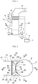
Fig. 1] Fig. 1 is a diagram schematically illustrating a configuration of a flue gas desulfurization apparatus according to an embodiment of the present invention. - [
Fig. 2] Fig. 2 is a cross-sectional view as seen along arrows II-II inFig. 1 . - [
Fig. 3] Fig. 3 is a cross-sectional view as seen along arrows III-III inFig. 2 . - [
Fig. 4] Fig. 4 is a cross-sectional view as seen along arrows IV-IV inFig. 2 . - [
Fig. 5] Fig. 5 is a perspective view of a connection bottom surface of an inlet flue as seen obliquely from above. - A flue gas desulfurization apparatus according to the present invention will be described with reference to the drawings.
- The flue gas desulfurization apparatus in this embodiment is a wet limestone-gypsum flue gas desulfurization apparatus that removes sulfur oxide in a combustion exhaust gas in order to prevent air pollution. In this desulfurization apparatus, as illustrated in
Fig. 1 , an exhaust gas from a combustion apparatus, such as a boiler, is introduced from an inlet flue 1 having the shape of a rectangular tube into anabsorption column 2. Anexhaust gas inlet 4 is provided in a cylindrical sidewall (peripheral wall) 3 of theabsorption column 2, and the downstream end of the inlet flue 1 is connected to theexhaust gas inlet 4. Inside theabsorption column 2,spray headers 13 are installed at a plurality of stages (two stages in the example ofFig. 1 ) in the gas flow direction, and eachspray header 13 is provided withmany spray nozzles 14 and sprays an absorption liquid from eachspray nozzle 14. When the exhaust gas flowing through theabsorption column 2 contacts droplets of the absorption liquid, the sulfur oxide in the exhaust gas is absorbed at the surfaces of the droplets along with soot and dust and acid gases such as hydrogen chloride (HCl) and hydrogen fluoride (HF) in the exhaust gas. - A
limestone slurry tank 5 containslimestone slurry 6 as a sulfur oxide absorber, and thislimestone slurry 6 is supplied to aliquid accumulation portion 8 at an inner lower section of theabsorption column 2 by a limestone slurry pump 7 according to the amount of the sulfur oxide to be absorbed in theabsorption column 2. - The absorption liquid in a slurry form in the
liquid accumulation portion 8 inside theabsorption column 2 is raised in pressure by an absorptionliquid circulation pump 9 to thereby be supplied to thespray headers 13 through acirculation piping 10. As mentioned above, eachspray header 13 is provided withmany spray nozzles 14, and the absorption liquid is sprayed from thespray nozzles 14 and makes gas-liquid contact with the exhaust gas. By reacting with the water in the absorption liquid, the sulfur oxide in the exhaust gas becomes sulfurous acid, which is an intermediate product, and drops into theliquid accumulation portion 8 of theabsorption column 2. - Air is supplied into the absorption liquid in the
absorption column 2 by anoxidation air blower 11. The sulfurous acid in theliquid accumulation portion 8 is oxidized by the supplied air to thereby become sulfuric acid, and then reacts with a calcium compound in the absorption liquid to thereby become an end product (gypsum). The exhaust gas with its sulfur oxide having moved to the absorption liquid side rises inside theabsorption column 2 and is discharged from anexhaust gas outlet 12. - The inlet flue 1 has an
inclined portion 15 inclined downward toward the downstream side in the flow direction of the exhaust gas, and aconnection portion 16 connecting the lower end of theinclined portion 15 and theexhaust gas inlet 4. As mentioned above, the inlet flue 1 is in the shape of a rectangular tube and, as illustrated inFigs. 2 ,3 and5 , the gas flow path in the inlet flue 1 is defined by abottom surface 17, atop surface 18, and left andright side surfaces 19. - An
upper edge 20 and alower edge 21 of the opening of theexhaust gas inlet 4 are in the shape of arcs separated from and facing each other vertically and extending and curved substantially horizontally, and theexhaust gas inlet 4 appears rectangular when viewed from inside the absorption column 2 (seeFigs. 4 and5 ). - As illustrated
Figs. 2 to 5 , thebottom surface 17 of the inlet flue 1 has the bottom surface of the inclined portion 15 (main bottom surface 22) and the bottom surface of the connection portion 16 (connection bottom surface 23). Themain bottom surface 22 is in a planar shape inclined downward toward the downstream side. Theconnection bottom surface 23 connects adownstream edge 24 of themain bottom surface 22 and thelower edge 21 of theexhaust gas inlet 4. Thedownstream edge 24 of themain bottom surface 22 extends straight substantially horizontally at a position higher than thelower edge 21 of theexhaust gas inlet 4. - The
connection bottom surface 23 is formed to be segmented into a plurality of surfaces. In this embodiment, the plurality of surfaces are formed of: aflat surface 25 extending substantially horizontally from thelower edge 21 of theexhaust gas inlet 4; a center downwardlyinclined surface 27 connecting thedownstream edge 24 of themain bottom surface 22 and anupstream edge 26 of theflat surface 25; and left and right downwardlyinclined surfaces 28 disposed on both the left and right sides of the center downwardlyinclined surface 27 and theflat surface 25. The center downwardlyinclined surface 27 is inclined downward toward theflat surface 25. The left and right downwardlyinclined surfaces 28 are inclined downward toward the center downwardlyinclined surface 27 and also inclined downward toward theflat surface 25. Specifically, the center downwardlyinclined surface 27 and the left and right downwardlyinclined surfaces 28 are each lower on theexhaust gas inlet 4 side than on themain bottom surface 22 side, and is inclined downward toward the downstream side of the exhaust gas. - The
upstream edge 26 of theflat surface 25 extends straight substantially horizontally so as to be substantially in parallel to thedownstream edge 24 of themain bottom surface 22 at a position obliquely below thedownstream edge 24, and the length of theupstream edge 26 of theflat surface 25 is smaller than the length of thedownstream edge 24 of themain bottom surface 22. Theflat surface 25 is defined by theupstream edge 26, thelower edge 21 of theexhaust gas inlet 4, and left and rightdownstream boundary lines 29 respectively connecting the left and right ends of theupstream edge 26 and the left and right ends of thelower edge 21. The center downwardlyinclined surface 27 is defined in a trapezoidal shape by thedownstream edge 24 of themain bottom surface 22, theupstream edge 26 of theflat surface 25, and left and rightupstream boundary lines 30 respectively connecting the left and right ends of thedownstream edge 24 and the left and right ends of theupstream edge 26. The left and right downwardlyinclined surfaces 28 are defined in triangular shapes by the left and rightdownstream boundary lines 29, the left and rightupstream boundary lines 30, andlower edges 31 of the left and right side surfaces 19 of theconnection portion 16. - The downstream end of the inlet flue 1 (connection portion 16) is reinforced by a plurality (four in this embodiment) of columnar
inner supports 32 standing so as to extend substantially vertically across the inside of the inlet flue 1. A lower portion of eachinner support 32 is supported on theflat surface 25 in theconnection bottom surface 23, whereas an upper portion of eachinner support 32 supports thetop surface 18 of theconnection portion 16. - At an upper end portion of the center downwardly inclined surface 27 (vicinity of the
downstream edge 24 of the main bottom surface 22), a cleaning water outflow tube (cleaning water outflow part) 33 is disposed straight along thedownstream edge 24 of themain bottom surface 22, cleaning water is ejected or jetted from a plurality of outflow portions (not illustrated) provided in the cleaningwater outflow tube 33 to thereby flow out. - The absorption liquid supplied into the
absorption column 2 enters theconnection portion 16 of the inlet flue 1 when the exhaust gas is introduced from the inlet flue 1 into theabsorption column 2. There is a possibility that the calcium compound in the absorption liquid having entered theconnection portion 16 turns into gypsum scale by being attached to theconnection bottom surface 23 and contacting the sulfur oxide in the exhaust gas. As a result of repeating a process in which the gypsum scale thus generated is dried by the exhaust gas and the absorption liquid is attached onto the dried gypsum scale again, scaling on theconnection bottom surface 23 progresses. As the scaling progresses, the gypsum scale narrows the exhaust gas flow path in the inlet flue 1, which increases the pressure drop in the inlet flue 1 and increases the power of the fan for sending the exhaust gas from the inlet flue 1 into theabsorption column 2. - According to this embodiment, the
connection bottom surface 23 is formed to be segmented into a plurality of surfaces, and each of the plurality of surfaces is one of the downwardlyinclined surface exhaust gas inlet 4 side than on themain bottom surface 22 side and inclined downward toward the downstream side of the exhaust gas or the substantially horizontalflat surface 25, and theconnection bottom surface 23 does not include an upwardly inclined surface being higher on theexhaust gas inlet 4 side (downstream side) than on themain bottom surface 22 side (inclined upward toward the downstream side of the exhaust gas). Also, in the vicinity of thedownstream edge 24 of themain bottom surface 22, the cleaningwater outflow tube 33 is provided, which causes cleaning water to flow out. - In this way, the scale attached to the
connection bottom surface 23 can be flushed from theexhaust gas inlet 4 at the downstream end of the inlet flue 1 into theabsorption column 2 with the cleaning water from the cleaningwater outflow tube 33. The scaling on thebottom surface 17 of the inlet flue 1 can therefore be suppressed. - Since the
upper edge 20 and thelower edge 21 of theexhaust gas inlet 4 are set so as to extend and be curved substantially horizontally, the shape of theexhaust gas inlet 4 is easily formable. - Since the plurality of surfaces in the
connection bottom surface 23 are formed of theflat surface 25, the center downwardlyinclined surface 27, and the left and right downwardlyinclined surfaces 28, the number of surfaces forming theconnection bottom surface 23 can be kept small. - Also, since the lower portions of the
inner supports 32 are supported by the substantially horizontalflat surface 25, the supported state of theinner supports 32 can be more stable than when the lower portions of theinner supports 32 are supported by an inclined surface. Moreover, it is possible to easily perform the work of mounting the inner supports 32. - Note that the present invention is not limited to the above embodiment described as an example and its modifications, and various changes can be made outside the above embodiment and the like according to the design and the like without departing from the technical idea of the present invention.
- For example, in the above embodiment, the plurality of surfaces in the
connection bottom surface 23 are formed of four surfaces of theflat surface 25, the center downwardlyinclined surface 27, and the left and right downwardlyinclined surfaces 28, but the number of surfaces forming theconnection bottom surface 23 is not limited to four and may be five or more. For example, at least one surface among theflat surface 25, the center downwardlyinclined surface 27, and the left and right downwardlyinclined surfaces 28 may further be segmented to increase the number of surfaces forming theconnection bottom surface 23. - Also, in the above embodiment, the method of supplying the absorption liquid into the
absorption column 2 is not limited to the spray method with thespray nozzles 14 as in the above embodiment, and may be another method (e.g., a liquid column method in which the absorption liquid is jetted upward from a lower side in the form of a column to thereby generate a liquid column, and the exhaust gas is brought into contact with the generated liquid column). -
- 1
- inlet flue
- 2
- absorption column
- 3
- sidewall of absorption column
- 4
- exhaust gas inlet
- 5
- limestone slurry tank
- 6
- limestone slurry
- 7
- limestone slurry pump
- 8
- liquid accumulation portion
- 9
- absorption liquid circulation pump
- 10
- circulation piping
- 11
- oxidation air blower
- 12
- exhaust gas outlet
- 13
- spray header
- 14
- spray nozzle
- 15
- inclined portion of inlet flue
- 16
- connection portion of inlet flue
- 17
- bottom surface of inlet flue
- 18
- top surface of inlet flue
- 19
- left and right side surfaces of inlet flue
- 20
- upper edge of exhaust gas inlet
- 21
- lower edge of exhaust gas inlet
- 22
- main bottom surface
- 23
- connection bottom surface
- 24
- downstream edge of main bottom surface
- 25
- flat surface
- 26
- upstream edge of flat surface
- 27
- center downwardly inclined surface
- 28
- left and right downwardly inclined surfaces
- 29
- downstream boundary line
- 30
- upstream boundary line
- 31
- lower edges of left and right side surfaces of connection portion
- 32
- inner support
- 33
- cleaning water outflow tube (cleaning water outflow part)
Claims (4)
- An exhaust gas inlet structure of an absorption column which absorbs and removes a predetermined substance in an exhaust gas, is provided with an exhaust gas inlet in a sidewall of the absorption column, with an inlet flue being connected to the exhaust gas inlet, and allows the exhaust gas from a combustion apparatus to flow through the inlet flue and flow into the absorption column from the exhaust gas inlet,wherein a lower edge of the exhaust gas inlet extends and is curved substantially horizontally,a bottom surface of the inlet flue has a planar main bottom surface and a connection bottom surface connecting a downstream edge of the main bottom surface and the lower edge of the exhaust gas inlet,the downstream edge of the main bottom surface extends straight substantially horizontally at a position higher than the lower edge of the exhaust gas inlet,the connection bottom surface is formed to be segmented into a plurality of surfaces, andeach of the plurality of surfaces is a downwardly inclined surface lower on the exhaust gas inlet side than on the main bottom surface side or a substantially horizontal flat surface.
- The exhaust gas inlet structure of an absorption column according to claim 1, wherein the plurality of surfaces include: a flat surface extending substantially horizontally from the lower edge of the exhaust gas inlet; a center downwardly inclined surface connecting the downstream edge of the main bottom surface and an upstream edge of the flat surface; and left and right downwardly inclined surfaces disposed on opposite sides of the center downwardly inclined surface and the flat surface.
- The exhaust gas inlet structure of an absorption column according to claim 2, whereina downstream end of the inlet flue is reinforced by a columnar inner support standing so as to extend substantially vertically across an inside of the inlet flue, anda lower portion of the inner support is supported on the flat surface.
- The exhaust gas inlet structure of an absorption column according to any one of claims 1 to 3, further comprising a cleaning water outflow part that causes cleaning water to flow out from a vicinity of the downstream edge of the main bottom surface.
Priority Applications (1)
| Application Number | Priority Date | Filing Date | Title |
|---|---|---|---|
| RS20260408A RS67949B1 (en) | 2019-04-24 | 2020-04-20 | Exhaust gas inlet structure of absorption column |
Applications Claiming Priority (2)
| Application Number | Priority Date | Filing Date | Title |
|---|---|---|---|
| JP2019083196A JP7091280B2 (en) | 2019-04-24 | 2019-04-24 | Exhaust gas inlet structure of absorption tower |
| PCT/JP2020/017054 WO2020218240A1 (en) | 2019-04-24 | 2020-04-20 | Exhaust gas inlet structure of absorption column |
Publications (3)
| Publication Number | Publication Date |
|---|---|
| EP3960276A1 true EP3960276A1 (en) | 2022-03-02 |
| EP3960276A4 EP3960276A4 (en) | 2023-01-25 |
| EP3960276B1 EP3960276B1 (en) | 2026-02-18 |
Family
ID=72942735
Family Applications (1)
| Application Number | Title | Priority Date | Filing Date |
|---|---|---|---|
| EP20794455.4A Active EP3960276B1 (en) | 2019-04-24 | 2020-04-20 | Exhaust gas inlet structure of absorption column |
Country Status (5)
| Country | Link |
|---|---|
| EP (1) | EP3960276B1 (en) |
| JP (1) | JP7091280B2 (en) |
| PL (1) | PL3960276T3 (en) |
| RS (1) | RS67949B1 (en) |
| WO (1) | WO2020218240A1 (en) |
Family Cites Families (7)
| Publication number | Priority date | Publication date | Assignee | Title |
|---|---|---|---|---|
| US5656046A (en) * | 1996-01-16 | 1997-08-12 | The Babcock & Wilcox Company | Inlet awning for high velocity absorbers |
| JP3978813B2 (en) * | 1997-06-20 | 2007-09-19 | 株式会社Ihi | Spray type square absorption tower of flue gas desulfurization equipment |
| JPH11156152A (en) * | 1997-11-28 | 1999-06-15 | Babcock Hitachi Kk | Absorption tower |
| JP4014063B2 (en) * | 1998-12-10 | 2007-11-28 | バブコック日立株式会社 | Self-supporting spray absorption tower and wet flue gas desulfurization equipment |
| JP2003103139A (en) * | 2001-09-28 | 2003-04-08 | Babcock Hitachi Kk | Wet flue gas desulfurization equipment |
| US20140112834A1 (en) * | 2012-10-23 | 2014-04-24 | Babcock & Wilcox Power Generation Group, Inc. | System and method for controlling scale build-up in a wfgd |
| JP5682045B1 (en) * | 2013-10-22 | 2015-03-11 | バブコック日立株式会社 | Wet flue gas desulfurization equipment |
-
2019
- 2019-04-24 JP JP2019083196A patent/JP7091280B2/en active Active
-
2020
- 2020-04-20 PL PL20794455.4T patent/PL3960276T3/en unknown
- 2020-04-20 WO PCT/JP2020/017054 patent/WO2020218240A1/en not_active Ceased
- 2020-04-20 RS RS20260408A patent/RS67949B1/en unknown
- 2020-04-20 EP EP20794455.4A patent/EP3960276B1/en active Active
Also Published As
| Publication number | Publication date |
|---|---|
| EP3960276A4 (en) | 2023-01-25 |
| JP2020179333A (en) | 2020-11-05 |
| WO2020218240A1 (en) | 2020-10-29 |
| RS67949B1 (en) | 2026-04-30 |
| JP7091280B2 (en) | 2022-06-27 |
| PL3960276T3 (en) | 2026-05-11 |
| EP3960276B1 (en) | 2026-02-18 |
Similar Documents
| Publication | Publication Date | Title |
|---|---|---|
| US6923852B2 (en) | Flue gas desulfurization system with a stepped tray | |
| US7976622B2 (en) | Wet flue gas desulfurization apparatus | |
| JP4845568B2 (en) | Wet flue gas desulfurization equipment | |
| US5512072A (en) | Flue gas scrubbing apparatus | |
| JP5634794B2 (en) | Apparatus and method for cleaning flue gas | |
| JP2015174025A (en) | Seawater flue gas desulfurization apparatus and application method of the same | |
| JP2014188406A (en) | Sea water flue gas desulfurization equipment and operation method thereof | |
| JP5437151B2 (en) | Flue gas desulfurization apparatus and oxygen combustion apparatus and method provided with the same | |
| JPWO2008035703A1 (en) | Wet flue gas desulfurization equipment | |
| WO2011126072A1 (en) | Wet flue gas desulfurization device | |
| JPH119956A (en) | Absorption tower of wet flue gas desulfurization unit | |
| EP3960276B1 (en) | Exhaust gas inlet structure of absorption column | |
| JP4905926B2 (en) | Two-chamber wet flue gas desulfurization system | |
| JP2003103139A (en) | Wet flue gas desulfurization equipment | |
| JPH115014A (en) | Wet exhaust gas desulfurization equipment | |
| JPH09141048A (en) | Wet exhaust gas desulfurization method and apparatus | |
| JP2002153727A (en) | Two-chamber wet flue gas desulfurization system | |
| JP3907873B2 (en) | Two-chamber wet flue gas desulfurization system | |
| JPH09313880A (en) | Exhaust gas treatment method and device | |
| JP2002273160A (en) | Two-chamber wet flue gas desulfurization system | |
| JP2001079337A (en) | Two-chamber wet flue gas desulfurization system | |
| JP5289668B2 (en) | Wet flue gas desulfurization equipment | |
| CN105536495A (en) | Side discharge type desulfurizing tower | |
| CN216654077U (en) | High-efficiency low-emission desulfurizing tower combining lime-gypsum method | |
| CN205340555U (en) | Formula of inclining out desulfurizing tower |
Legal Events
| Date | Code | Title | Description |
|---|---|---|---|
| STAA | Information on the status of an ep patent application or granted ep patent |
Free format text: STATUS: THE INTERNATIONAL PUBLICATION HAS BEEN MADE |
|
| PUAI | Public reference made under article 153(3) epc to a published international application that has entered the european phase |
Free format text: ORIGINAL CODE: 0009012 |
|
| STAA | Information on the status of an ep patent application or granted ep patent |
Free format text: STATUS: REQUEST FOR EXAMINATION WAS MADE |
|
| 17P | Request for examination filed |
Effective date: 20211119 |
|
| AK | Designated contracting states |
Kind code of ref document: A1 Designated state(s): AL AT BE BG CH CY CZ DE DK EE ES FI FR GB GR HR HU IE IS IT LI LT LU LV MC MK MT NL NO PL PT RO RS SE SI SK SM TR |
|
| DAV | Request for validation of the european patent (deleted) | ||
| RAX | Requested extension states of the european patent have changed |
Extension state: BA Payment date: 20211119 |
|
| RAP1 | Party data changed (applicant data changed or rights of an application transferred) |
Owner name: MITSUBISHI HEAVY INDUSTRIES, LTD. |
|
| A4 | Supplementary search report drawn up and despatched |
Effective date: 20221223 |
|
| RIC1 | Information provided on ipc code assigned before grant |
Ipc: B01D 53/78 20060101ALI20221220BHEP Ipc: B01D 53/50 20060101ALI20221220BHEP Ipc: B01D 53/18 20060101AFI20221220BHEP |
|
| GRAP | Despatch of communication of intention to grant a patent |
Free format text: ORIGINAL CODE: EPIDOSNIGR1 |
|
| STAA | Information on the status of an ep patent application or granted ep patent |
Free format text: STATUS: GRANT OF PATENT IS INTENDED |
|
| INTG | Intention to grant announced |
Effective date: 20250912 |
|
| GRAS | Grant fee paid |
Free format text: ORIGINAL CODE: EPIDOSNIGR3 |
|
| GRAA | (expected) grant |
Free format text: ORIGINAL CODE: 0009210 |
|
| STAA | Information on the status of an ep patent application or granted ep patent |
Free format text: STATUS: THE PATENT HAS BEEN GRANTED |
|
| AK | Designated contracting states |
Kind code of ref document: B1 Designated state(s): AL AT BE BG CH CY CZ DE DK EE ES FI FR GB GR HR HU IE IS IT LI LT LU LV MC MK MT NL NO PL PT RO RS SE SI SK SM TR |
|
| REG | Reference to a national code |
Ref country code: CH Ref legal event code: F10 Free format text: ST27 STATUS EVENT CODE: U-0-0-F10-F00 (AS PROVIDED BY THE NATIONAL OFFICE) Effective date: 20260218 Ref country code: GB Ref legal event code: FG4D |
|
| REG | Reference to a national code |
Ref country code: IE Ref legal event code: FG4D |
|
| REG | Reference to a national code |
Ref country code: DE Ref legal event code: R096 Ref document number: 602020067149 Country of ref document: DE |
|
| REG | Reference to a national code |
Ref country code: NL Ref legal event code: MP Effective date: 20260218 |
|
| PG25 | Lapsed in a contracting state [announced via postgrant information from national office to epo] |
Ref country code: ES Free format text: LAPSE BECAUSE OF FAILURE TO SUBMIT A TRANSLATION OF THE DESCRIPTION OR TO PAY THE FEE WITHIN THE PRESCRIBED TIME-LIMIT Effective date: 20260218 |
|
| PGFP | Annual fee paid to national office [announced via postgrant information from national office to epo] |
Ref country code: RS Payment date: 20260408 Year of fee payment: 7 Ref country code: PL Payment date: 20260415 Year of fee payment: 7 |
|
| PG25 | Lapsed in a contracting state [announced via postgrant information from national office to epo] |
Ref country code: GR Free format text: LAPSE BECAUSE OF FAILURE TO SUBMIT A TRANSLATION OF THE DESCRIPTION OR TO PAY THE FEE WITHIN THE PRESCRIBED TIME-LIMIT Effective date: 20260519 |
|
| REG | Reference to a national code |
Ref country code: LT Ref legal event code: MG9D |
|
| PG25 | Lapsed in a contracting state [announced via postgrant information from national office to epo] |
Ref country code: LT Free format text: LAPSE BECAUSE OF FAILURE TO SUBMIT A TRANSLATION OF THE DESCRIPTION OR TO PAY THE FEE WITHIN THE PRESCRIBED TIME-LIMIT Effective date: 20260218 |
|
| PG25 | Lapsed in a contracting state [announced via postgrant information from national office to epo] |
Ref country code: NO Free format text: LAPSE BECAUSE OF FAILURE TO SUBMIT A TRANSLATION OF THE DESCRIPTION OR TO PAY THE FEE WITHIN THE PRESCRIBED TIME-LIMIT Effective date: 20260518 |
|
| PG25 | Lapsed in a contracting state [announced via postgrant information from national office to epo] |
Ref country code: AT Free format text: LAPSE BECAUSE OF FAILURE TO SUBMIT A TRANSLATION OF THE DESCRIPTION OR TO PAY THE FEE WITHIN THE PRESCRIBED TIME-LIMIT Effective date: 20260218 Ref country code: FI Free format text: LAPSE BECAUSE OF FAILURE TO SUBMIT A TRANSLATION OF THE DESCRIPTION OR TO PAY THE FEE WITHIN THE PRESCRIBED TIME-LIMIT Effective date: 20260218 Ref country code: SE Free format text: LAPSE BECAUSE OF FAILURE TO SUBMIT A TRANSLATION OF THE DESCRIPTION OR TO PAY THE FEE WITHIN THE PRESCRIBED TIME-LIMIT Effective date: 20260218 |
|
| REG | Reference to a national code |
Ref country code: AT Ref legal event code: MK05 Ref document number: 1887502 Country of ref document: AT Kind code of ref document: T Effective date: 20260218 |
|
| PG25 | Lapsed in a contracting state [announced via postgrant information from national office to epo] |
Ref country code: HR Free format text: LAPSE BECAUSE OF FAILURE TO SUBMIT A TRANSLATION OF THE DESCRIPTION OR TO PAY THE FEE WITHIN THE PRESCRIBED TIME-LIMIT Effective date: 20260218 |
|
| PG25 | Lapsed in a contracting state [announced via postgrant information from national office to epo] |
Ref country code: PT Free format text: LAPSE BECAUSE OF FAILURE TO SUBMIT A TRANSLATION OF THE DESCRIPTION OR TO PAY THE FEE WITHIN THE PRESCRIBED TIME-LIMIT Effective date: 20260618 Ref country code: IS Free format text: LAPSE BECAUSE OF FAILURE TO SUBMIT A TRANSLATION OF THE DESCRIPTION OR TO PAY THE FEE WITHIN THE PRESCRIBED TIME-LIMIT Effective date: 20260618 |
|
| PG25 | Lapsed in a contracting state [announced via postgrant information from national office to epo] |
Ref country code: NL Free format text: LAPSE BECAUSE OF FAILURE TO SUBMIT A TRANSLATION OF THE DESCRIPTION OR TO PAY THE FEE WITHIN THE PRESCRIBED TIME-LIMIT Effective date: 20260218 |
|
| PG25 | Lapsed in a contracting state [announced via postgrant information from national office to epo] |
Ref country code: LV Free format text: LAPSE BECAUSE OF FAILURE TO SUBMIT A TRANSLATION OF THE DESCRIPTION OR TO PAY THE FEE WITHIN THE PRESCRIBED TIME-LIMIT Effective date: 20260218 |
|
| PG25 | Lapsed in a contracting state [announced via postgrant information from national office to epo] |
Ref country code: BG Free format text: LAPSE BECAUSE OF FAILURE TO SUBMIT A TRANSLATION OF THE DESCRIPTION OR TO PAY THE FEE WITHIN THE PRESCRIBED TIME-LIMIT Effective date: 20260218 |