JP5437151B2 - Flue gas desulfurization apparatus and oxygen combustion apparatus and method provided with the same - Google Patents
Flue gas desulfurization apparatus and oxygen combustion apparatus and method provided with the same Download PDFInfo
- Publication number
- JP5437151B2 JP5437151B2 JP2010101919A JP2010101919A JP5437151B2 JP 5437151 B2 JP5437151 B2 JP 5437151B2 JP 2010101919 A JP2010101919 A JP 2010101919A JP 2010101919 A JP2010101919 A JP 2010101919A JP 5437151 B2 JP5437151 B2 JP 5437151B2
- Authority
- JP
- Japan
- Prior art keywords
- desulfurization
- gas
- exhaust gas
- absorption
- combustion
- Prior art date
- Legal status (The legal status is an assumption and is not a legal conclusion. Google has not performed a legal analysis and makes no representation as to the accuracy of the status listed.)
- Expired - Fee Related
Links
- 238000006477 desulfuration reaction Methods 0.000 title claims description 160
- 230000023556 desulfurization Effects 0.000 title claims description 160
- 238000002485 combustion reaction Methods 0.000 title claims description 42
- UGFAIRIUMAVXCW-UHFFFAOYSA-N Carbon monoxide Chemical compound [O+]#[C-] UGFAIRIUMAVXCW-UHFFFAOYSA-N 0.000 title claims description 30
- 239000003546 flue gas Substances 0.000 title claims description 30
- QVGXLLKOCUKJST-UHFFFAOYSA-N atomic oxygen Chemical compound [O] QVGXLLKOCUKJST-UHFFFAOYSA-N 0.000 title claims description 27
- 239000001301 oxygen Substances 0.000 title claims description 27
- 229910052760 oxygen Inorganic materials 0.000 title claims description 27
- 238000000034 method Methods 0.000 title description 5
- 239000007789 gas Substances 0.000 claims description 208
- 238000010521 absorption reaction Methods 0.000 claims description 126
- 239000007788 liquid Substances 0.000 claims description 84
- 239000007921 spray Substances 0.000 claims description 30
- 238000011084 recovery Methods 0.000 claims description 27
- 230000001590 oxidative effect Effects 0.000 claims description 23
- 238000004519 manufacturing process Methods 0.000 claims description 8
- 239000000567 combustion gas Substances 0.000 claims description 6
- 238000007599 discharging Methods 0.000 claims description 4
- XTQHKBHJIVJGKJ-UHFFFAOYSA-N sulfur monoxide Chemical class S=O XTQHKBHJIVJGKJ-UHFFFAOYSA-N 0.000 claims description 3
- 235000008733 Citrus aurantifolia Nutrition 0.000 claims description 2
- 235000011941 Tilia x europaea Nutrition 0.000 claims description 2
- 238000009841 combustion method Methods 0.000 claims description 2
- 239000004571 lime Substances 0.000 claims description 2
- 229910052815 sulfur oxide Inorganic materials 0.000 claims 1
- 238000005192 partition Methods 0.000 description 18
- XLYOFNOQVPJJNP-UHFFFAOYSA-N water Substances O XLYOFNOQVPJJNP-UHFFFAOYSA-N 0.000 description 17
- 239000002250 absorbent Substances 0.000 description 15
- 230000002745 absorbent Effects 0.000 description 15
- 239000003595 mist Substances 0.000 description 15
- LSNNMFCWUKXFEE-UHFFFAOYSA-N Sulfurous acid Chemical compound OS(O)=O LSNNMFCWUKXFEE-UHFFFAOYSA-N 0.000 description 12
- 238000005260 corrosion Methods 0.000 description 10
- 230000007797 corrosion Effects 0.000 description 10
- IJGRMHOSHXDMSA-UHFFFAOYSA-N Atomic nitrogen Chemical compound N#N IJGRMHOSHXDMSA-UHFFFAOYSA-N 0.000 description 6
- 239000000446 fuel Substances 0.000 description 6
- 239000000463 material Substances 0.000 description 6
- MWUXSHHQAYIFBG-UHFFFAOYSA-N nitrogen oxide Inorganic materials O=[N] MWUXSHHQAYIFBG-UHFFFAOYSA-N 0.000 description 5
- 230000003647 oxidation Effects 0.000 description 5
- 238000007254 oxidation reaction Methods 0.000 description 5
- 239000003245 coal Substances 0.000 description 4
- 239000000428 dust Substances 0.000 description 4
- 230000000694 effects Effects 0.000 description 4
- 230000002378 acidificating effect Effects 0.000 description 3
- 229910052757 nitrogen Inorganic materials 0.000 description 3
- QAOWNCQODCNURD-UHFFFAOYSA-N Sulfuric acid Chemical compound OS(O)(=O)=O QAOWNCQODCNURD-UHFFFAOYSA-N 0.000 description 2
- 238000006243 chemical reaction Methods 0.000 description 2
- 230000003247 decreasing effect Effects 0.000 description 2
- 238000010586 diagram Methods 0.000 description 2
- TXKMVPPZCYKFAC-UHFFFAOYSA-N disulfur monoxide Inorganic materials O=S=S TXKMVPPZCYKFAC-UHFFFAOYSA-N 0.000 description 2
- 238000005507 spraying Methods 0.000 description 2
- 238000003756 stirring Methods 0.000 description 2
- 238000003860 storage Methods 0.000 description 2
- 238000011144 upstream manufacturing Methods 0.000 description 2
- 239000002253 acid Substances 0.000 description 1
- 238000013019 agitation Methods 0.000 description 1
- 230000004888 barrier function Effects 0.000 description 1
- 238000007664 blowing Methods 0.000 description 1
- 239000012141 concentrate Substances 0.000 description 1
- 239000000470 constituent Substances 0.000 description 1
- 238000005536 corrosion prevention Methods 0.000 description 1
- 238000007865 diluting Methods 0.000 description 1
- 229910052602 gypsum Inorganic materials 0.000 description 1
- 239000010440 gypsum Substances 0.000 description 1
- 238000002347 injection Methods 0.000 description 1
- 239000007924 injection Substances 0.000 description 1
- 238000010248 power generation Methods 0.000 description 1
- 230000003134 recirculating effect Effects 0.000 description 1
- 239000002912 waste gas Substances 0.000 description 1
Images


Classifications
-
- Y02E20/344—
Landscapes
- Combustion Of Fluid Fuel (AREA)
- Treating Waste Gases (AREA)
- Gas Separation By Absorption (AREA)
- Air Supply (AREA)
Description
本発明は、火力発電用ボイラプラント等において、燃焼排ガスに含まれるSO2(硫黄酸化物)を除去する排煙脱硫装置(以下、単に脱硫装置ということもある)及びこの排煙脱硫装置を備え、空気から窒素分を分離して得られた酸素を用いて石炭等の燃料をボイラで燃焼させる酸素燃焼システムに関するものである。 The present invention includes a flue gas desulfurization device (hereinafter also simply referred to as a desulfurization device) for removing SO 2 (sulfur oxide) contained in combustion exhaust gas in a boiler plant for thermal power generation, and the flue gas desulfurization device. The present invention relates to an oxyfuel combustion system in which fuel such as coal is burned in a boiler using oxygen obtained by separating nitrogen from air.
従来の脱硫装置3の構成例を図7に示す。
脱硫装置3は主に、脱硫吸収液6を噴霧するスプレノズル4、吸収液循環ポンプ5、ミストエリミネータ8、脱硫吸収液6中に生成した亜硫酸の酸化用ガス供給部9、攪拌機10、吸収液を溜めて亜硫酸を酸化する吸収液溜め部11等から構成される。
A configuration example of a
The
脱硫装置3は前記吸収液貯め部11の上側に図示しない燃焼装置からの排ガスをほぼ水平方向に導入する入口ダクト1と排ガスをほぼ水平方向に排出する出口ダクト2をそれぞれ対向する側壁に設けた脱硫吸収部26がある。該入口ダクト1と出口ダクト2の間の脱硫装置3の内部の空間には排ガス流路があり、該排ガス流路は脱硫装置3の内部の空間を二室に分割する仕切板22で仕切られている。該仕切板22の下端部側を吸収液に浸漬され、上端部は脱硫装置3の内部の天井に達しない高さまであり、排ガス流路内を流れる排ガスは入口ダクト1側の空間を仕切板22に沿って上昇し、脱硫装置3の内部の天井と仕切板22の上端部との間の開口部からなる流路から出口ダクト2側の空間に向かって降下し、出口ダクト2から排出する。
In the
脱硫装置3の内部は仕切板22で仕切られた排ガスが上向きに流れる上昇流領域29と、天井側の開口部で反転した後に出口ダクト2に向けて下向きに排ガスが流れる下降流領域30が形成され、それぞれの領域29,30に設置したスプレノズル4から噴霧される吸収液6と排ガスを接触させて、排ガス中のSO2を除去する(特許文献1)。
Inside the
排ガス中のSO2を吸収することで吸収液6中で生成した亜硫酸を酸化するために、下降流領域に設けられる酸化用ガス供給部9から酸化用ガス27である空気を供給する。空気により亜硫酸が酸化され、石膏となって脱硫装置3から排出される。
In order to oxidize sulfurous acid generated in the absorbing
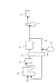
次に 空気から窒素分を分離して得られた酸素を用い、石炭等の燃料をボイラで燃焼させる酸素燃焼システムの例を図6に示す。
前記酸素燃焼システムは、ボイラ13で酸素を用いて燃料を燃焼させた排ガスが流れる排ガス流路に上流側から順に、ボイラ13、脱硝装置14、熱交換器15、集塵装置16、脱硫装置3、CO2回収装置17、再循環ライン18が配置され、さらに酸素製造装置19及び酸素供給ライン20等も配置された構成である。
Next, FIG. 6 shows an example of an oxyfuel combustion system that uses oxygen obtained by separating nitrogen from air and burns fuel such as coal in a boiler.
In the oxyfuel combustion system, the
酸素製造装置19により空気から窒素分と分離された酸素は、酸素供給ライン20等からボイラ13に供給され、燃料である石炭25を酸素燃焼することにより生成した排ガスを脱硝装置14に導き、排ガスに含まれるNOx(窒素酸化物)を分解する。脱硝装置14から排出された排ガスは熱交換器15を通じて再循環ガスと熱交換され、熱交換器15の出口温度200〜160℃程度まで降下した後、集塵装置16で煤塵が除去される。
集塵装置16で除塵された排ガスの一部は脱硫装置3に供給されて、SO2が除去され、CO2回収装置17へ導かれる。また、脱硫装置3に供給しない一部の排ガスは、再循環ガスとして再循環ライン18を通り、熱交換器15で200℃まで昇温された後、ボイラ13に燃焼用ガスとして供給する構成となっている。
The oxygen separated from the air by the
Part of the exhaust gas removed by the
酸素燃焼システムでは、脱硫装置3からCO2回収装置17に導かれる排ガス中に含まれる残留SO2がCO2回収装置17で圧縮され、冷却される過程で液化して硫酸となってCO2回収装置17を構成する材料の腐食を引き起こす可能性があるため、CO2回収装置17を持たない空気燃焼式のシステムに比べ、脱硫装置3出口における残留SO2濃度を極力低減する必要がある。
In the oxyfuel combustion system, the residual SO 2 contained in the exhaust gas led from the
一方、再循環ガスとして再循環ライン(排ガス再循環系統)18に戻す排ガスも燃焼システム全体としてSO2が濃縮するのを回避するため、ある程度脱硫することが望ましい。
上記図6に示す酸素燃焼システムでは、再循環ガスとして再循環ライン18に戻す排ガスは脱硫されないため、燃焼システム全体としてSO2が濃縮し、再循環ライン18でダクト材料の腐食等を引き起こす可能性がある。
On the other hand, the exhaust gas returned to the recirculation line (exhaust gas recirculation system) 18 as recirculation gas is desirably desulfurized to some extent in order to avoid the concentration of SO 2 as the whole combustion system.
In the oxyfuel combustion system shown in FIG. 6 above, the exhaust gas that is returned to the
また、脱硫装置3の入口ダクト2の排ガス中のSO2濃度が高いので、従来と同じ脱硫率では、出口ダクト2の排ガス中のSO2濃度が高くなり、上述したCO2回収装置17を構成する材料の腐食の問題が顕著となるおそれがある。そこで、再循環ライン18を脱硫装置3の後流側からボイラ13側に戻す構成とすることが考えられる(特許文献2,3)。
Further, since the SO 2 concentration in the exhaust gas of the
上記従来技術では脱硫装置3における脱硫率を左右する要素は、L/G(液ガス比)とガス流速であるが、再循環ガス量はCO2回収装置17へ送られる回収ガス量に比べて多いため、排ガス全量をCO2回収装置17へ送られる回収ガス側の要求SO2濃度に合わせて高度に脱硫するとなると、極めて多量の脱硫吸収液を用いる必要が生じ、ポンプ動力等、大幅なユーティリティの増大につながるという問題がある。
In the above prior art, the factors that influence the desulfurization rate in the
そこで、本発明の課題は、多量の脱硫吸収液を用いることなく、ポンプ動力等の大幅なユーティリティの増大を招くことなく、一つの脱硫装置でボイラ側(再循環ライン側)とCO2回収装置側とに求められるSO2濃度に応じた異なる脱硫率の排ガス処理を行い、CO2回収装置の腐食防止と燃焼システム全体としてのSO2濃縮防止を図ることができる排ガス脱硫率を高めた排煙脱硫装置及びこれを備えた酸素燃焼装置と方法を提供することである。 Therefore, an object of the present invention is to use a single desulfurization apparatus and a CO 2 recovery apparatus without using a large amount of desulfurization absorption liquid and without causing a significant increase in utilities such as pump power. Exhaust flue gas with increased exhaust gas desulfurization rate that can treat the exhaust gas with different desulfurization rates depending on the SO 2 concentration required by the side and prevent corrosion of the CO 2 recovery device and SO 2 concentration as a whole combustion system A desulfurization apparatus and an oxyfuel combustion apparatus and method including the same are provided.
本発明の課題は次の解決手段で達成される。
請求項1記載の発明は、ボイラ等の燃焼装置(13)から排出される燃焼排ガスを導入してスプレノズル(4)から噴霧した石灰分を含む脱硫吸収液(6)と気液接触させて排ガス中の硫黄酸化物を除去する脱硫吸収部(26)と、前記気液接触後の脱硫吸収液(6)を貯留する脱硫吸収液溜め部(11)とを備えた湿式排煙脱硫装置(3)であって、
脱硫吸収部(26)には、前記燃焼排ガスを導入する入口ダクト(1)と、該入口ダクト(1)から導入した排ガスが上向きに流れる上昇流領域(29)を形成して該上降流領域(29)に前記スプレノズル(4)の一部が配置される第1の吸収部と、該第1の吸収部のガス流れの後流側に排ガスが下向きに流れる下降流領域(30)を形成して該下降流領域(30)に前記スプレノズル(4)の他部が配置される第2の吸収部と、該第2の吸収部から浄化したガスを外部に排出する出口ダクト(2)とを備え、前記第1の吸収部の上部に空間部を形成し、該空間部には第1の吸収部を経た排ガスの一部を燃焼装置(13)へ供給するために再循環ガスとして利用するための再循環出口ダクト(2’)を接続したことを特徴とする排煙脱硫装置である。
The object of the present invention is achieved by the following means.
The invention according to claim 1 introduces combustion exhaust gas discharged from a combustion apparatus (13) such as a boiler and makes it contact with a desulfurization absorption liquid (6) containing lime sprayed from a spray nozzle (4) to make gas and liquid contact. Wet flue gas desulfurization device (3) provided with a desulfurization absorption part (26) for removing sulfur oxide therein and a desulfurization absorption liquid reservoir part (11) for storing the desulfurization absorption liquid (6) after the gas-liquid contact. ) And
The desulfurization absorption part (26) forms an inlet duct (1) for introducing the combustion exhaust gas and an upward flow region (29) through which the exhaust gas introduced from the inlet duct (1) flows upward. A first absorption portion in which a part of the spray nozzle (4) is disposed in the region (29), and a downward flow region (30) in which exhaust gas flows downward on the downstream side of the gas flow of the first absorption portion. A second absorption part formed and disposed in the downward flow region (30) with the other part of the spray nozzle (4), and an outlet duct (2) for discharging the gas purified from the second absorption part to the outside And forming a space in the upper part of the first absorption part, and supplying a part of the exhaust gas that has passed through the first absorption part to the combustion device (13) as a recirculation gas in the space part A flue gas desulfurization apparatus characterized by connecting a recirculation outlet duct (2 ') for use It is.
請求項2記載の発明は、前記脱硫吸収部(26)が、前記脱硫吸収液溜め部(11)の脱硫吸収液(6)の液面よりも低い位置であって、前記酸化用ガス供給部(9)が設けられた壁面から離れた前記脱硫吸収液溜め部(11)の中央寄りに、該吸収液溜め部(11)の水平断面積以下の水平断面積を持つ下端開口部(7b)を設けた水封管(7)を有することを特徴とする請求項1記載の湿式排煙脱硫装置である。
The invention according to
請求項3記載の発明は、上昇流領域(29)と下降流領域(30)の断面積比が4:1〜29:1になるように設置し、下降流領域(30)のガス流速を4〜27m/sにしたことを特徴とする請求項1記載の湿式排煙脱硫装置である。
The invention according to
請求項4記載の発明は、酸素製造装置(19)と、該酸素製造装置(19)で製造した酸素と請求項1に記載の排煙脱硫装置(3)の再循環出口ダクト(2’)から排出される排ガスを燃焼装置(13)の燃焼用ガスの一部として供給する排ガス再循環ライン(18)と、請求項1に記載の排煙脱硫装置(3)と、該排煙脱硫装置(3)の出口ダクト(2)から浄化処理した排ガスを導入して排ガス中のCO2を回収するCO2回収装置(17)とを設けたことを特徴とする酸素燃焼装置である。 The invention according to claim 4 is an oxygen production device (19), oxygen produced by the oxygen production device (19), and a recirculation outlet duct (2 ') of the flue gas desulfurization device (3) according to claim 1. An exhaust gas recirculation line (18) for supplying exhaust gas discharged from the combustion apparatus (13) as part of the combustion gas, the flue gas desulfurization device (3) according to claim 1, and the flue gas desulfurization device An oxyfuel combustion apparatus provided with a CO 2 recovery device (17) for introducing the purified exhaust gas from the outlet duct (2) of (3) and recovering CO 2 in the exhaust gas.
請求項5記載の発明は、請求項1に記載の排煙脱硫装置(3)の再循環出口ダクト(2’)から排出される排ガスと酸素製造装置(19)で製造した酸素を燃焼装置(13)の燃焼用ガスの一部として供給し、請求項1に記載の排煙脱硫装置(3)の出口ダクト(2)から浄化処理した排ガスを導入して排ガス中のCO2をCO2回収装置(17)で回収することを特徴とする酸素燃焼方法である。
The invention according to
請求項1記載の発明によれば、本発明によれば、脱硫装置3内の上昇流領域29で、排ガス中のSO2をある程度除去できるため、排ガス中のSO2濃度が増加するのを防止することができる。したがって、脱硫装置3内の下降流領域30で、SO2をさらに効率よく除去できるため、再循環出口ダクト2’からのSO2濃度が低減された排ガスを燃焼装置の再循環ガスとして利用することができる。
According to the first aspect of the present invention, according to the present invention, SO 2 in the exhaust gas can be removed to some extent in the
請求項2記載の発明によれば、請求項1記載の発明の効果に加えて、脱硫装置のスプレー部の壁面を該吸収液溜め部11に挿入し、いわゆる水封管7とし、該水封管7の水平断面積を該吸収液溜め部11の水平断面積以下としたので、供給する酸化用ガス27の気泡が上昇する速度よりも、速く吸収液が下降流を形成し、脱硫装置(吸収液)内でSO2の吸収に伴って生成した亜硫酸の酸化に用いる酸化用ガスが排ガス中に放散して排ガスが希釈されるのを防止できる。
According to the invention described in
また、脱硫吸収部26と脱硫吸収液溜め部11とを水封管7により分離するようになるので、脱硫吸収液6中に生成する亜硫酸の酸化用ガス27が脱硫装置3の出口ガス中に混入することがないため、脱硫装置3の後流側に配置される、例えばCO2回収装置17の入口のCO2濃度が低下するのを防止し、CO2回収率の低下を防止する効果がある。
Further, since the
請求項3記載の発明によれば、請求項1記載の発明の効果に加えて、上昇流領域29と下降流領域30の断面積比が4:1〜29:1になるように設置したので、脱硫装置3の下降流領域30では上昇流領域29に比べてガス処理量が少なくて済む上、ガス流速を高めることができるので高度な脱硫(高脱硫率)を行うことができる。
According to the third aspect of the invention, in addition to the effect of the first aspect of the invention, the cross-sectional area ratio between the
したがって脱硫装置3の出口ダクト2から排出される排ガス中の残留SO2濃度を極めて低くすることができ、後流側に配置されるCO2回収装置17などの機器を構成する材料の腐食の可能性を低減できる。
Therefore, the residual SO 2 concentration in the exhaust gas discharged from the
さらに下降流領域30のガス流速を高めることができるので低濃度のSO2も効率よく除去することができるようになり、例えば前記CO2回収装置17などの腐食の防止や安定な運転をすることができる。
Furthermore, since the gas flow rate in the
請求項4、5記載の発明によれば、過剰に供給した酸素をボイラの燃焼ガスに利用できるため、余分な酸素を使うことがなく、設備コスト低減の効果がある。 According to the fourth and fifth aspects of the present invention, since the excessively supplied oxygen can be used as the combustion gas of the boiler, excess oxygen is not used, and there is an effect of reducing the equipment cost.
さらに、請求項4、5に記載の発明によれば、排煙脱硫装置を備え、空気から窒素分を分離して得られた酸素を用い、石炭等の燃料をボイラで燃焼させる酸素燃焼システムとし、一つの脱硫装置3でボイラ側(再循環ライン18側)とCO2回収装置17側とに求められるSO2濃度に応じた異なる脱硫率の排ガス処理を行い、ユーティリティの大幅な増大を招くことなく、CO2回収装置17の腐食防止と燃焼システム全体としてのSO2濃縮防止を図ることができる。 また、脱硫吸収液6中に生成する亜硫酸の酸化用ガス27に高濃度な酸素を用いて、亜硫酸の酸化に利用されなかった余剰の酸素を燃焼装置13へ供給する循環ライン18に供給することで、酸化用ガスに空気を用いた場合よりも、供給ガス量を低減できる。従って、ガス供給動力を低減できる。あわせて、脱硫吸収液面の上昇を防止して、吸収液溜め部11のサイズをコンパクト化でき、設備コストを低減できる。
Furthermore, according to invention of
本発明の実施例を図面と共に説明する。従来技術と共通する構成、作用については説明を省略する。 Embodiments of the present invention will be described with reference to the drawings. A description of the configuration and operation common to those of the prior art will be omitted.
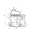
本実施例1の酸素燃焼システムにおける脱硫装置の構成を図1に示し、この脱硫装置をボイラの酸素燃焼システムに適用した例を図2に示す。 FIG. 1 shows the configuration of a desulfurization apparatus in the oxyfuel combustion system of the first embodiment, and FIG. 2 shows an example in which this desulfurization apparatus is applied to an oxyfuel combustion system of a boiler.
脱硫装置3は主に、ボイラなどの燃焼装置13(図2)から排出される排ガスを導入する入口ダクト1、導入した排ガスに脱硫吸収液6を噴霧するためにスプレ配管21と該配管21に設けられたスプレノズル4、脱硫装置3の底部(吸収液溜め部11)に溜まった吸収液6を該スプレノズル4へ循環供給する吸収液循環ポンプ5、排ガス出口ダクト2と排ガスの再循環出口ダクト2’に設置されたミストエリミネータ8、脱硫吸収液6中に生成した亜硫酸の酸化用ガス供給部9、吸収液溜め部11の吸収液6を攪拌する攪拌機10、脱硫装置3の内部の排ガス流路となる空間を二室に分割する仕切板22などから構成される。
The
仕切板22の下端部側は吸収液溜め部11内の吸収液6中に浸漬され、上端部は脱硫装置3の内部の天井に達しない高さまであり、排ガス流路は入口ダクト1側の空間を仕切板22に沿って上昇し、脱硫装置3の内部の天井と仕切板22の上端部との間の開口部からなる流路から出口ダクト2側の室に向かって降下する。
The lower end side of the
脱硫装置3は前記吸収液貯め部11の上側に図2に示す燃焼装置13からの排ガスをほぼ水平方向に導入する入口ダクト1と排ガスをほぼ水平方向に排出する出口ダクト2をそれぞれ対向する側壁に設け、さらに入口ダクト1と出口ダクト2の間の脱硫装置3の内部の空間は仕切板22で二室に分割されている。排ガスは入口ダクト1側の空間を仕切板22に沿って上昇し、脱硫装置3の天井と仕切板22の上端部との間の開口部から出口ダクト2側の空間に向かって降下し、出口ダクト2及び後述する再循環出口ダクト2’から排出する。
The
このように脱硫装置3の内部に入口ダクト1から導入された排ガスの流路は仕切板22で仕切られて上向きに流れる上昇流領域29と、天井側の開口部で反転した後に出口ダクト2に向けて下向きに排ガスが流れる下降流領域30からなり、それぞれの領域29,30に設置したスプレノズル4から噴霧される吸収液6と排ガスが接触して排ガス中のSO2を除去する。本明細書では前記上昇流領域29を第1の吸収部、下降流領域30を第2の吸収部ということがある。
なお、脱硫装置3における前記第1の吸収部と第2の吸収部からなる部位を脱硫吸収部26とし、該脱硫吸収部26より下方の吸収液6が溜まる部位を吸収液溜め部11とする。
In this way, the flow path of the exhaust gas introduced from the inlet duct 1 into the
In the
また前記上昇流領域(第1の吸収部)29と下降流領域(第2の吸収部)30との間に形成された空間部からは排ガスの一部をボイラ13へ再循環させる再循環ライン18(図2)に通じる再循環出口ダクト2’が接続されている。再循環ライン18に接続される再循環出口ダクト2’にはミストエリミネータ8を設けることが望ましい。
A recirculation line for recirculating a part of the exhaust gas to the
ここで上昇流領域29を通過した排ガスは、上昇流領域29と下降流領域30との間に形成された空間部を経て、再循環ライン18側に流れる排ガスと下降流領域30に流れる排ガスとに分かれるが、ガス量としては、定格運転時において概ね75%から80%のガスが再循環出口ダクト2’を経由して再循環ライン18から排出され、残りのガスは出口ダクト2から排出される。
Here, the exhaust gas that has passed through the
上昇流領域29におけるガス流速は、例えば3〜4m/sとすることが一般的である。下降流領域30のガス流速を上昇流領域29におけるガス流速と同じにした場合、上昇流領域(第1の吸収部)29と下降流領域(第2の吸収部)30の断面積比は3:1〜4:1となるが、必ずしもガス流速を同じに設定する必要はなく、両者のガス流速及び再循環ライン18側に流れる排ガスと第2の吸収部側に流れる排ガスの流量設定とに応じて第1の吸収部と第2の吸収部の断面積比も異なってくる。
The gas flow rate in the
なお、排ガスが上向きに流れる上昇流領域29にスプレノズル4を設置した第1の吸収部が設けられ、下降流領域30に同じく第2の吸収部が設けられ、さらに第1の吸収部と第2の吸収部との間からボイラ13へ再循環させる再循環ライン18が接続されるように排ガス流路が構成されていれば、必ずしも上記の形態に限定されるものではない。
In addition, the 1st absorption part which installed the spray nozzle 4 in the upward flow area |
即ち、隣接する第1の吸収部と第2の吸収部を区分するのは、必ずしも仕切板22のように薄い板状の部材でなくとも良く、スプレノズル4の上下方向、水平方向の配置や配管、スプレの噴射方向(上向き、下向き、その他)等、入口ダクト1、出口ダクト2の位置や形状、吸収塔の上部空間部において再循環ライン18に接続されるダクトの位置や形状等も特に限定されない。
That is, the adjacent first absorption portion and the second absorption portion may not necessarily be a thin plate-like member like the
下降流領域30のガス流れを横断する方向の断面積は上昇流領域29の断面積よりも小さく、第1と第2の吸収部のガス流路断面積に対する各吸収部の長さ(ガス流路)が相対的に長いため、気液接触が吸収部(ガス流路)断面方向にムラ無く行われ、また、ガスが吹き抜けしにくいので、効率良くSO2を除去することができる。さらに、スプレノズル4を流路内に設けずに壁面に設置して、相対的に圧力損失を低減した形態を採用することもできる。
The cross-sectional area in the direction crossing the gas flow in the
本実施形態によれば、一つの脱硫装置3の第1の吸収部29と第2の吸収部30とで異なる脱硫率の排ガス処理を行うことができるため、後段の機器で要求される異なる脱硫率に応じて複数の脱硫装置を設置するための設備コストの増大を招くことが無い。
According to the present embodiment, since the exhaust gas treatment with different desulfurization rates can be performed in the
例えば、複数の脱硫装置を直列に接続して、その途中から再循環ライン18側の排ガスを取り出し、残りの排ガスをさらに脱硫してCO2回収装置17へ導く場合や、必ずしも高度な脱硫は要求されないが、処理ガス量が多い再循環ライン用と処理ガス量は少ないが高度な脱硫を要求されるCO2回収装置17用にそれぞれ別々の脱硫装置3を並列して設ける場合よりも設備コストを低減することができる。
For example, a case where a plurality of desulfurization apparatuses are connected in series, the exhaust gas on the
ガス流路断面積の大きい第1の吸収部とその後流側にガス流路断面積の小さい第2の吸収部が形成されるので、後述するように第2の吸収部は相対的に断面積に対する流路長さが長く、吸収液に対してガスが吹き抜けにくい特徴を有し、CO2回収装置17側へ排出するガスに対して高度な脱硫が行える。 Since the first absorption part having a large gas channel cross-sectional area and the second absorption part having a small gas channel cross-sectional area are formed on the downstream side, the second absorption part has a relatively cross-sectional area as will be described later. The length of the flow path with respect to the gas is long, and the gas does not easily blow through the absorption liquid, and the gas discharged to the CO 2 recovery device 17 side can be highly desulfurized.
第1の吸収部と第2の吸収部の間から再循環ライン18に流れる排ガスを取り出すので第1の吸収部でSO2を吸収した酸性のミストを、この再循環ライン18側に導いて捕集することにより、第2の吸収部側に、この酸性のミストが流入しにくく、第2の吸収部において噴射する脱硫吸収液6がガス中に残留するSO2の除去に有効に使われるようにすることができるのである。
Since the exhaust gas flowing into the
空気燃焼システムの排ガス中のSO2濃度は燃料の種類にも依存するが150〜4000ppm程度である。
従来型の脱硫装置を備えた酸素燃焼システムにおいて、脱硫装置3の前流側からボイラ13へ排ガスを再循環させると、再循環させるガス中のSO2は除去されないため、系内でSO2が濃縮し、脱硫装置3の入口のSO2濃度が750〜20、000ppmと空気燃焼システムの約5倍に増加する。
The SO 2 concentration in the exhaust gas of the air combustion system is about 150 to 4000 ppm, although it depends on the type of fuel.
In an oxyfuel combustion system equipped with a conventional desulfurization apparatus, when exhaust gas is recirculated from the upstream side of the
図1に示した本発明の脱硫装置3は排ガスを系内でSO2が濃縮しない程度、あるいは再循環ライン18や熱交換器15、ボイラ13において構成材料等に腐食の問題が生じない程度に脱硫してからボイラに再循環する。このため、脱硫装置3入口の排ガス中のSO2濃度が高まるのを防止することができる。
The
脱硫装置3の上昇流領域29に設けられた第1の吸収部で排ガスは、ある程度脱硫されるため、下降流領域30へ向かう排ガス中のSO2濃度を低くすることができ、下降流領域30に設けられた第2の吸収部での脱硫に関する負荷を低減し、最終的に脱硫装置3の出口ダクト2から排出されるガス中のSO2濃度をCO2回収装置17での腐食の問題が生じない程度まで低くすることができる。
なお、上昇流領域領域29と下降流領域30の断面積比が(3:1〜4:1)であり、下降流領域30のガス流域を3〜4m/sとしている。
Since the exhaust gas is desulfurized to some extent in the first absorption section provided in the
The cross-sectional area ratio between the
再循環ライン18に接続される再循環出口ダクト2’にはミストエリミネータ8が設けられ、上昇流領域29とその上部の空間部に至るまで上向きに排ガスが流れることから、再循環出口ダクト2’にあるミストエリミネータ8におけるミスト捕集効率が高められる。このため、再循環ライン18側に流れるガス中の残留SO2により、ミストエリミネータ8の後流側の再循環ライン18にあるダクトや機器類の材料に腐食が生じるリスクを低減できる。
The
上昇流領域29に設けられた第1の吸収部の上部の空間部では、排ガスに同伴されて吹き上げられた吸収液ミストは、一部がここで滞留成長して落下しやすくなる。
また、上昇流領域29に設けられた第1の吸収部を経て、その上部の空間部に達した排ガスのうち、全ガス量の75〜80%のガスは天井部9の再循環出口ダクト2’から再循環ライン18に排出される一方、残り20〜25%程度のガスは下降流領域30に設けられた第2の吸収部へ流れるが、ガス流れの向きが上向きから下向きに転じるので、大部分のミストは慣性力によって、75〜80%のガスとともに再循環ライン18側に排出される。特に図1に示す構成例では再循環ライン18に通じる天井部9の再循環出口ダクト2’が脱硫装置(吸収塔)3の上部に設けられているので、その働きが顕著である。
In the upper space part of the first absorption part provided in the
Further, of the exhaust gas that has reached the upper space through the first absorption section provided in the
そのため、下降流領域30に設けられた第2の吸収部へ上昇流領域29で吸収されたSO2を含む酸性のミストが飛散する量を低減でき、第2の吸収部でSO2を含む酸性のミストとスプレノズル4から噴射される吸収液6中に含まれるアルカリ分との反応を少なくできることから、ガス中の残留SO2との反応が優先的になり、第2の吸収部でのSO2の除去性能が大幅に向上するという利点がある。
Therefore, the amount of acidic mist containing SO 2 absorbed in the
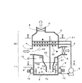
本発明の他の実施例を図3に示す。本実施例は図1に示す脱硫装置3におけるスプレーノズル4のある脱硫吸収部26の下端を脱硫吸収液溜め部11の液面より下側に挿入し、この部分は、いわゆる水封管7を形成する。該水封管7の断面積を該吸収液溜め部11の断面積以下とし、該水封管7の水平断面積は該脱硫液溜め部11に供給する酸化用ガス27の気泡が上昇する速度よりも、速く吸収液6が下降流を形成するような水封管7の前記断面積とした。
Another embodiment of the present invention is shown in FIG. In this embodiment, the lower end of the
吸収液溜め部11内に設けた酸化用ガス供給部9を水封管7の外側に設けた。また、吸収液溜め部11の上部の気相6bに酸化用ガス出口配管12を設けた。脱硫装置3の吸収液溜め部11の気相6bは水封管7の隔壁7aにより脱硫吸収部26と隔離されている。これにより、亜硫酸の酸化で利用されなかった酸化用ガス27は出口ダクト2や再循環ライン18に混入することなく、酸化用ガス出口配管12から系外に排出される構造とした。
An oxidizing gas supply unit 9 provided in the absorbing
脱硫吸収液6は、吸収液循環ポンプ5により吸収液溜め部11から吸引され、スプレノズル4を通じて脱硫吸収部26へ噴射されており、吸収液溜め部11では攪拌機10により、主に水封管7の隔壁7aの外側を循環している。このため脱硫装置3の脱硫吸収部26から落下して水封管7に流入する脱硫吸収液6の流れが上側から下側に向けて一方向に流れるので、水封管7の内部での脱硫吸収液6の沈降速度が早く、気泡が上昇しにくいという特性がある。
The
したがって、酸化用ガス供給部9から脱硫吸収液6に供給された酸化用ガス27が脱硫吸収部26へ向かう動きに対して、水封管7の隔壁7aが障壁として作用することに加えて、水封管7の内部での脱硫吸収液6の下向きの流れにより、その動きを制限する。
Therefore, in addition to the
このため、脱硫装置3の吸収液中で生成する亜硫酸の酸化用ガス27が脱硫装置出口ダクト2の排ガスに混入するのを防止し、脱硫装置3の後段に配置されるCO2回収装置装置17の入口におけるCO2濃度が低下することを防止でき、高効率なCO2回収ができる。
For this reason, the sulfurous
本実施例の構成では、上述のとおり、脱硫装置3の脱硫吸収部26から落下し、水封管7に流入してくる吸収液の流れが水封管7の下端部の開口部7bに向けて上方から下方へ一方向の流れになっており、水封管7の内部での吸収液の沈降速度が早く、気泡が上昇しにくいという特性がある。また、水封管7は、吸収液溜め部11の水面下の底部付近に挿入されているので、脱硫装置3内の吸収液6を吸収液溜め部11に容易に流下させることができ、該流下する吸収液6により吸収液溜め部11の脱硫吸収液6の攪拌に寄与するので、攪拌機10の台数低減もしくは攪拌機10の小型化が可能であり、コスト低減が期待できる。
In the configuration of the present embodiment, as described above, the flow of the absorbing liquid that falls from the
さらに、脱硫吸収液溜め部11で用いる攪拌機10による気泡の攪拌・微細化も進み易くなる。
仮に脱硫吸収部26にある水封管7の下端部開口部7bを通じて酸化用ガスが排ガス中に放出されることがあっても、その量は軽減され、排ガスが希釈されにくい。
Furthermore, the agitation / miniaturization of bubbles by the
Even if the oxidizing gas may be released into the exhaust gas through the
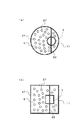
図4(a)に、図3におけるA−A’線断面矢視図を示し、この実施例では水封管7や脱硫吸収液溜め部11の水平断面が円形になった場合の構造を示す。スプレノズル4からスプレされた液滴は排ガスと接触した後、水封管7を通過して酸化用ガス27が供給されている外側の脱硫吸収液部6に供給される。
FIG. 4A shows a cross-sectional view taken along the line AA ′ in FIG. 3, and in this embodiment, a structure when the horizontal cross section of the
また、図4(b)に、図3におけるA−A’線断面矢視図の一例として、水封管7や脱硫吸収液溜め部11の水平断面が円形以外のケース、例えば、四角の形状の場合の実施例を示す。このように、特に断面の形状にこだわる必要はなく、水封管の断面積が小さい場合に、酸化用ガスが供給されるスペースが大きくなり、亜硫酸の酸化効率は高くなる。
4B, as an example of a cross-sectional view taken along line AA ′ in FIG. 3, a case where the horizontal cross section of the
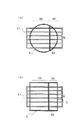
本発明の他の実施例を図5に示す。図5は図1または図3の脱硫装置3において、B−B’線の断面矢視図の一例である。図5(a)は脱硫装置3の脱硫吸収液溜め部26の水平断面形状が円形になった場合の下降流側である下降流領域30のガス流速を上昇流領域29のガス流速よりも速くなるように水平断面形状を設定した例である。
具体的には、脱硫吸収液溜め部26の上昇流領域29と下降流領域30の断面積比が4:1〜29:1になるように設置し、下降流領域30のガス流速を4〜27m/sにする。
Another embodiment of the present invention is shown in FIG. FIG. 5 is an example of a sectional view taken along line BB ′ in the
Specifically, the desulfurization
脱硫吸収液溜め部26の下降流領域30の水平断面積を上昇流領域29のそれより小さくすると、圧力損失が大きくなるため、図示していない脱硫装置3の後流側で用いるファンの動力が大きくなる。一方、下降流領域30の水平断面積を上昇流領域29のそれより小さくすると、ガスの流速が高くなることから、SO2の除去性能が高くなるため、吸収液6の噴霧量を低減でき、吸収液循環ポンプ5の動力は小さくなる。ファンと吸収液循環ポンプ5の動力は小さく、SO2除去性能が高い範囲が断面積比4:1〜29:1、下降流領域30のガス流速は4〜27m/sとなる。
If the horizontal cross-sectional area of the
脱硫吸収液溜め部26の下降流領域30に設けられた第2の吸収部の導入部付近でのSO2濃度は低くなっている。排ガス中のSO2ガスが低濃度である場合は、当該SO2ガスのガス流速を高めると、効率よく除去できることが分かっていることから、本実施形態によれば下降流領域30に設けられた第2の吸収部におけるガスを高効率で脱硫することができる。このため、脱硫装置3のコンパクト化と脱硫装置3の後流側に配置される機器への残留SO2飛散量を低減できる。
The SO 2 concentration in the vicinity of the introduction portion of the second absorption portion provided in the
前記下降流領域30では、水平断面積が上昇流領域29のそれよりも小さく、ガス流路の前記水平断面積に対するガス流路長さが大きいため、壁面にスプレノズル4を設置して吸収液6を噴霧しても、ガスが吹き抜けることなく、効率良くSO2を除去することができる。
In the
また、前記上昇流領域29と下降流領域30の断面積の比が最大29:1となり、壁面の間の距離が短くなっていることから、脱硫装置3の側壁面にスプレノズル4を設置しても良く、この場合は対抗壁までスプレ液滴の速度が低減するのを抑制することができ、ガスとスプレ液滴の相対速度を高く維持できることから、下降流領域30の速度を3〜4m/sにした場合よりも、高効率にSO2を除去することができる。
Moreover, since the ratio of the cross-sectional area of the
なお、上述した上昇流領域29と下降流領域30の断面積比およびガス流速の範囲は、特に本実施例に限定されるものではなく、本発明の全ての形態に共通して適用することができる。
The above-described cross-sectional area ratio and the range of the gas flow velocity between the
図5(b)は図1または図3の脱硫装置3において、B−B’線断面が多角形(図5(b)の場合四角形)の場合の一例である。図4と同様に前記断面が円形である必要はなく、多角形の場合でも同様に、下降流領域30の排ガス流速が、上昇流領域29の排ガス流速よりも速くなるように、下降流領域30のガス流れを横断する方向の断面積を決定すれば良い。
FIG. 5B is an example in the case where the B-B ′ line cross section is a polygon (in the case of FIG. 5B, a rectangle) in the
下降流領域30では、ガス流れを横断する方向の断面積が上昇流領域29側のガス流れを横断する方向の断面積よりも小さいため、壁面からスプレノズル4を設置して吸収液6を噴霧しても、ガスが吹き抜けることなく、効率良くSO2を除去することができる。
In the
本発明による脱硫装置は、高効率で排ガス中のSO2を除去することで、CO2回収装置の腐食を防止できるため、産業上の利用可能性が高い。 The desulfurization apparatus according to the present invention has high industrial applicability because it can prevent corrosion of the CO 2 recovery apparatus by removing SO 2 in the exhaust gas with high efficiency.
1 入口ダクト 2 排ガス出口ダクト
2’ 天井部排ガス出口ダクト
3 脱硫装置 4 スプレノズル
5 吸収液循環ポンプ 6 脱硫吸収液
6b 吸収液溜め部の気相 7 水封管
7a 水封管開口部 7b 水封管隔壁
8 ミストエリミネータ 9 酸化用ガス供給部
10 攪拌機 11 吸収液溜め部
13 燃焼装置(ボイラ) 15 熱交換器
17 CO2回収装置 18 再循環ライン
21 スプレ配管 22 仕切板
26 脱硫吸収部 27 酸化用ガス
29 上昇流領域 30 下降流領域
DESCRIPTION OF SYMBOLS 1
Claims (5)
脱硫吸収部(26)には、前記燃焼排ガスを導入する入口ダクト(1)と、該入口ダクト(1)から導入した排ガスが上向きに流れる上昇流領域(29)を形成して該上降流領域(29)に前記スプレノズル(4)の一部が配置される第1の吸収部と、該第1の吸収部のガス流れの後流側に排ガスが下向きに流れる下降流領域(30)を形成して該下降流領域(30)に前記スプレノズル(4)の他部が配置される第2の吸収部と、該第2の吸収部から浄化したガスを外部に排出する出口ダクト(2)とを備え、前記第1の吸収部の上部に空間部を形成し、該空間部には第1の吸収部を経た排ガスの一部を燃焼装置(13)へ供給するために再循環ガスとして利用するための再循環出口ダクト(2’)を接続したことを特徴とする排煙脱硫装置。 Combustion exhaust gas discharged from a combustion apparatus (13) such as a boiler is introduced and brought into gas-liquid contact with a desulfurization absorption liquid (6) containing lime sprayed from a spray nozzle (4) to remove sulfur oxides in the exhaust gas. A wet flue gas desulfurization device (3) comprising a desulfurization absorption part (26) and a desulfurization absorption liquid reservoir (11) for storing the desulfurization absorption liquid (6) after the gas-liquid contact,
The desulfurization absorption part (26) forms an inlet duct (1) for introducing the combustion exhaust gas and an upward flow region (29) through which the exhaust gas introduced from the inlet duct (1) flows upward. A first absorption portion in which a part of the spray nozzle (4) is disposed in the region (29), and a downward flow region (30) in which exhaust gas flows downward on the downstream side of the gas flow of the first absorption portion. A second absorption part formed and disposed in the downward flow region (30) with the other part of the spray nozzle (4), and an outlet duct (2) for discharging the gas purified from the second absorption part to the outside And forming a space in the upper part of the first absorption part, and supplying a part of the exhaust gas that has passed through the first absorption part to the combustion device (13) as a recirculation gas in the space part A flue gas desulfurization apparatus characterized by connecting a recirculation outlet duct (2 ') for use .
該酸素製造装置(19)で製造した酸素と請求項1に記載の排煙脱硫装置(3)の再循環出口ダクト(2’)から排出される排ガスを燃焼装置(13)の燃焼用ガスの一部として供給する排ガス再循環ライン(18)と、
請求項1に記載の排煙脱硫装置(3)と、
該排煙脱硫装置(3)の出口ダクト(2)から浄化処理した排ガスを導入して排ガス中のCO2を回収するCO2回収装置(17)と
を設けたことを特徴とする酸素燃焼装置。 An oxygen production device (19);
The oxygen produced by the oxygen production device (19) and the exhaust gas discharged from the recirculation outlet duct (2 ') of the flue gas desulfurization device (3) according to claim 1 are used as the combustion gas of the combustion device (13). An exhaust gas recirculation line (18) to be supplied as a part,
The flue gas desulfurization device (3) according to claim 1,
An oxyfuel combustion apparatus comprising a CO 2 recovery device (17) for introducing a purified exhaust gas from an outlet duct (2) of the flue gas desulfurization device (3) and recovering CO 2 in the exhaust gas .
Priority Applications (1)
| Application Number | Priority Date | Filing Date | Title |
|---|---|---|---|
| JP2010101919A JP5437151B2 (en) | 2010-04-27 | 2010-04-27 | Flue gas desulfurization apparatus and oxygen combustion apparatus and method provided with the same |
Applications Claiming Priority (1)
| Application Number | Priority Date | Filing Date | Title |
|---|---|---|---|
| JP2010101919A JP5437151B2 (en) | 2010-04-27 | 2010-04-27 | Flue gas desulfurization apparatus and oxygen combustion apparatus and method provided with the same |
Publications (2)
| Publication Number | Publication Date |
|---|---|
| JP2011230047A JP2011230047A (en) | 2011-11-17 |
| JP5437151B2 true JP5437151B2 (en) | 2014-03-12 |
Family
ID=45319952
Family Applications (1)
| Application Number | Title | Priority Date | Filing Date |
|---|---|---|---|
| JP2010101919A Expired - Fee Related JP5437151B2 (en) | 2010-04-27 | 2010-04-27 | Flue gas desulfurization apparatus and oxygen combustion apparatus and method provided with the same |
Country Status (1)
| Country | Link |
|---|---|
| JP (1) | JP5437151B2 (en) |
Families Citing this family (7)
| Publication number | Priority date | Publication date | Assignee | Title |
|---|---|---|---|---|
| CA2809655A1 (en) * | 2010-05-18 | 2011-11-24 | Babcock-Hitachi Kabushiki Kaisha | Flue gas desulfurization device, combustion system, and combustion method |
| US8882896B2 (en) * | 2011-12-02 | 2014-11-11 | Fluor Technologies Corporation | Multi-directional outlet transition and hood |
| JP2016052629A (en) * | 2014-09-04 | 2016-04-14 | 株式会社Ihi | Desulfurization apparatus |
| KR101525929B1 (en) * | 2014-12-11 | 2015-06-04 | 지이큐솔루션 주식회사 | The method and device for disposing of waste gas |
| CN105289215B (en) * | 2015-11-20 | 2018-06-19 | 长沙华时捷环保科技发展股份有限公司 | Flue gas circulation desulfuration method and system |
| CN117046284A (en) * | 2017-07-25 | 2023-11-14 | 史汉祥 | Flue gas purifying reactor |
| CN115121113A (en) * | 2022-04-02 | 2022-09-30 | 成都达奇环境科技有限公司 | Air inlet structure, catalytic flue gas desulfurization device and desulfurization method |
Family Cites Families (6)
| Publication number | Priority date | Publication date | Assignee | Title |
|---|---|---|---|---|
| JP3068888B2 (en) * | 1991-05-28 | 2000-07-24 | 株式会社日立製作所 | Combustion apparatus and operation method thereof |
| JPH09313877A (en) * | 1996-05-23 | 1997-12-09 | Babcock Hitachi Kk | Flue gas desulfurizer and method thereof |
| JP3140392B2 (en) * | 1997-03-31 | 2001-03-05 | 川崎重工業株式会社 | Spray absorption tower |
| JP3907873B2 (en) * | 1999-07-08 | 2007-04-18 | バブコック日立株式会社 | Two-chamber wet flue gas desulfurization system |
| JP4644725B2 (en) * | 2008-05-07 | 2011-03-02 | 株式会社日立製作所 | Oxy-combustion boiler system, pulverized-coal-fired boiler remodeling method, oxy-combustion boiler system control device |
| JP5281871B2 (en) * | 2008-11-10 | 2013-09-04 | バブコック日立株式会社 | Boiler plant |
-
2010
- 2010-04-27 JP JP2010101919A patent/JP5437151B2/en not_active Expired - Fee Related
Also Published As
| Publication number | Publication date |
|---|---|
| JP2011230047A (en) | 2011-11-17 |
Similar Documents
| Publication | Publication Date | Title |
|---|---|---|
| JP5668244B2 (en) | Flue gas desulfurization apparatus, combustion system, and combustion method | |
| JP5437151B2 (en) | Flue gas desulfurization apparatus and oxygen combustion apparatus and method provided with the same | |
| JP6223654B2 (en) | Flue gas desulfurization equipment | |
| US5674459A (en) | Hydrogen peroxide for flue gas desulfurization | |
| US20090277334A1 (en) | Wet flue gas desulfurization apparatus | |
| US20090173234A1 (en) | Wet-type exhaust gas desulfurizer | |
| JP2009240908A (en) | Wet two step flue gas desulfurization apparatus and operation method of wet two step flue gas desulfurization apparatus | |
| JP2014188406A (en) | Sea water flue gas desulfurization equipment and operation method thereof | |
| WO2008035703A1 (en) | Wet-type exhaust desulfurizing apparatus | |
| JP5967306B2 (en) | Desulfurization equipment | |
| JPH119956A (en) | Absorption tower of wet flue gas desulfurizer | |
| CN101342455B (en) | Rotational flow and spray combined desulfurizing device | |
| CN105148698A (en) | Boiler flue gas desulfurization and denitrification system | |
| WO2013115108A1 (en) | Oxidation tank, seawater flue-gas desulfurization system and power generation system | |
| CN108970355A (en) | A kind of wet-dry change coupling smoke processing system and method | |
| WO2014196458A1 (en) | Device for desulfurization with seawater and system for desulfurization with seawater | |
| JP2011031209A (en) | Wet type flue gas desulfurization apparatus | |
| JP6296884B2 (en) | Flue gas desulfurization equipment | |
| JP2012213737A (en) | Flue gas desulfurization apparatus and oxygen-combusting flue gas treatment system | |
| JP3904771B2 (en) | Two-chamber wet flue gas desulfurization system | |
| JPH10118451A (en) | Exhaust gas treatment apparatus and method | |
| TWI765136B (en) | Water treatment tank and desulfuration apparatus | |
| JP3842706B2 (en) | Wet flue gas desulfurization apparatus and method | |
| CN105396451A (en) | A process for highly efficient removal of SO3 by washing with alkaline solution in a spray desulfurization tower | |
| JP4719117B2 (en) | Exhaust gas treatment method |
Legal Events
| Date | Code | Title | Description |
|---|---|---|---|
| A621 | Written request for application examination |
Free format text: JAPANESE INTERMEDIATE CODE: A621 Effective date: 20130423 |
|
| A977 | Report on retrieval |
Free format text: JAPANESE INTERMEDIATE CODE: A971007 Effective date: 20131108 |
|
| TRDD | Decision of grant or rejection written | ||
| A01 | Written decision to grant a patent or to grant a registration (utility model) |
Free format text: JAPANESE INTERMEDIATE CODE: A01 Effective date: 20131119 |
|
| A61 | First payment of annual fees (during grant procedure) |
Free format text: JAPANESE INTERMEDIATE CODE: A61 Effective date: 20131211 |
|
| R150 | Certificate of patent or registration of utility model |
Free format text: JAPANESE INTERMEDIATE CODE: R150 |
|
| S111 | Request for change of ownership or part of ownership |
Free format text: JAPANESE INTERMEDIATE CODE: R313111 |
|
| R350 | Written notification of registration of transfer |
Free format text: JAPANESE INTERMEDIATE CODE: R350 |
|
| LAPS | Cancellation because of no payment of annual fees |