EP3958795B1 - Systèmes d'implant glénoïde - Google Patents
Systèmes d'implant glénoïde Download PDFInfo
- Publication number
- EP3958795B1 EP3958795B1 EP20794900.9A EP20794900A EP3958795B1 EP 3958795 B1 EP3958795 B1 EP 3958795B1 EP 20794900 A EP20794900 A EP 20794900A EP 3958795 B1 EP3958795 B1 EP 3958795B1
- Authority
- EP
- European Patent Office
- Prior art keywords
- glenoid
- anchoring structure
- implant system
- liner
- wall
- Prior art date
- Legal status (The legal status is an assumption and is not a legal conclusion. Google has not performed a legal analysis and makes no representation as to the accuracy of the status listed.)
- Active
Links
- 241001653121 Glenoides Species 0.000 title claims description 159
- 239000007943 implant Substances 0.000 title claims description 71
- 238000004873 anchoring Methods 0.000 claims description 106
- 235000010627 Phaseolus vulgaris Nutrition 0.000 claims description 2
- 244000046052 Phaseolus vulgaris Species 0.000 claims description 2
- 210000000988 bone and bone Anatomy 0.000 description 7
- 230000008878 coupling Effects 0.000 description 7
- 238000010168 coupling process Methods 0.000 description 7
- 238000005859 coupling reaction Methods 0.000 description 7
- 238000011882 arthroplasty Methods 0.000 description 6
- 230000007246 mechanism Effects 0.000 description 6
- 239000002184 metal Substances 0.000 description 4
- 238000000034 method Methods 0.000 description 4
- 230000002093 peripheral effect Effects 0.000 description 4
- 208000024288 Rotator Cuff injury Diseases 0.000 description 3
- 238000006243 chemical reaction Methods 0.000 description 3
- 239000011248 coating agent Substances 0.000 description 3
- 238000000576 coating method Methods 0.000 description 3
- 210000004095 humeral head Anatomy 0.000 description 3
- 239000004698 Polyethylene Substances 0.000 description 2
- 206010003246 arthritis Diseases 0.000 description 2
- 210000002758 humerus Anatomy 0.000 description 2
- 230000004048 modification Effects 0.000 description 2
- 238000012986 modification Methods 0.000 description 2
- 238000010883 osseointegration Methods 0.000 description 2
- -1 polyethylene Polymers 0.000 description 2
- 229920000573 polyethylene Polymers 0.000 description 2
- 210000000513 rotator cuff Anatomy 0.000 description 2
- 208000036487 Arthropathies Diseases 0.000 description 1
- 208000012659 Joint disease Diseases 0.000 description 1
- 206010023204 Joint dislocation Diseases 0.000 description 1
- 208000008877 Shoulder Dislocation Diseases 0.000 description 1
- 230000001154 acute effect Effects 0.000 description 1
- 210000000845 cartilage Anatomy 0.000 description 1
- 230000007850 degeneration Effects 0.000 description 1
- 210000000852 deltoid muscle Anatomy 0.000 description 1
- 208000015181 infectious disease Diseases 0.000 description 1
- 230000013011 mating Effects 0.000 description 1
- 210000003205 muscle Anatomy 0.000 description 1
- 201000008482 osteoarthritis Diseases 0.000 description 1
- 239000004033 plastic Substances 0.000 description 1
- 229920003023 plastic Polymers 0.000 description 1
- 230000008439 repair process Effects 0.000 description 1
- 210000000323 shoulder joint Anatomy 0.000 description 1
- 238000001356 surgical procedure Methods 0.000 description 1
- 230000007704 transition Effects 0.000 description 1
Images


Classifications
-
- A—HUMAN NECESSITIES
- A61—MEDICAL OR VETERINARY SCIENCE; HYGIENE
- A61F—FILTERS IMPLANTABLE INTO BLOOD VESSELS; PROSTHESES; DEVICES PROVIDING PATENCY TO, OR PREVENTING COLLAPSING OF, TUBULAR STRUCTURES OF THE BODY, e.g. STENTS; ORTHOPAEDIC, NURSING OR CONTRACEPTIVE DEVICES; FOMENTATION; TREATMENT OR PROTECTION OF EYES OR EARS; BANDAGES, DRESSINGS OR ABSORBENT PADS; FIRST-AID KITS
- A61F2/00—Filters implantable into blood vessels; Prostheses, i.e. artificial substitutes or replacements for parts of the body; Appliances for connecting them with the body; Devices providing patency to, or preventing collapsing of, tubular structures of the body, e.g. stents
- A61F2/02—Prostheses implantable into the body
- A61F2/30—Joints
- A61F2/40—Joints for shoulders
- A61F2/4081—Glenoid components, e.g. cups
-
- A—HUMAN NECESSITIES
- A61—MEDICAL OR VETERINARY SCIENCE; HYGIENE
- A61F—FILTERS IMPLANTABLE INTO BLOOD VESSELS; PROSTHESES; DEVICES PROVIDING PATENCY TO, OR PREVENTING COLLAPSING OF, TUBULAR STRUCTURES OF THE BODY, e.g. STENTS; ORTHOPAEDIC, NURSING OR CONTRACEPTIVE DEVICES; FOMENTATION; TREATMENT OR PROTECTION OF EYES OR EARS; BANDAGES, DRESSINGS OR ABSORBENT PADS; FIRST-AID KITS
- A61F2/00—Filters implantable into blood vessels; Prostheses, i.e. artificial substitutes or replacements for parts of the body; Appliances for connecting them with the body; Devices providing patency to, or preventing collapsing of, tubular structures of the body, e.g. stents
- A61F2/02—Prostheses implantable into the body
- A61F2/30—Joints
- A61F2/30721—Accessories
- A61F2/30749—Fixation appliances for connecting prostheses to the body
-
- A—HUMAN NECESSITIES
- A61—MEDICAL OR VETERINARY SCIENCE; HYGIENE
- A61L—METHODS OR APPARATUS FOR STERILISING MATERIALS OR OBJECTS IN GENERAL; DISINFECTION, STERILISATION OR DEODORISATION OF AIR; CHEMICAL ASPECTS OF BANDAGES, DRESSINGS, ABSORBENT PADS OR SURGICAL ARTICLES; MATERIALS FOR BANDAGES, DRESSINGS, ABSORBENT PADS OR SURGICAL ARTICLES
- A61L27/00—Materials for grafts or prostheses or for coating grafts or prostheses
- A61L27/50—Materials characterised by their function or physical properties, e.g. injectable or lubricating compositions, shape-memory materials, surface modified materials
- A61L27/56—Porous materials, e.g. foams or sponges
-
- A—HUMAN NECESSITIES
- A61—MEDICAL OR VETERINARY SCIENCE; HYGIENE
- A61F—FILTERS IMPLANTABLE INTO BLOOD VESSELS; PROSTHESES; DEVICES PROVIDING PATENCY TO, OR PREVENTING COLLAPSING OF, TUBULAR STRUCTURES OF THE BODY, e.g. STENTS; ORTHOPAEDIC, NURSING OR CONTRACEPTIVE DEVICES; FOMENTATION; TREATMENT OR PROTECTION OF EYES OR EARS; BANDAGES, DRESSINGS OR ABSORBENT PADS; FIRST-AID KITS
- A61F2/00—Filters implantable into blood vessels; Prostheses, i.e. artificial substitutes or replacements for parts of the body; Appliances for connecting them with the body; Devices providing patency to, or preventing collapsing of, tubular structures of the body, e.g. stents
- A61F2/02—Prostheses implantable into the body
- A61F2/30—Joints
- A61F2002/30001—Additional features of subject-matter classified in A61F2/28, A61F2/30 and subgroups thereof
- A61F2002/30108—Shapes
- A61F2002/3011—Cross-sections or two-dimensional shapes
- A61F2002/30112—Rounded shapes, e.g. with rounded corners
- A61F2002/30113—Rounded shapes, e.g. with rounded corners circular
-
- A—HUMAN NECESSITIES
- A61—MEDICAL OR VETERINARY SCIENCE; HYGIENE
- A61F—FILTERS IMPLANTABLE INTO BLOOD VESSELS; PROSTHESES; DEVICES PROVIDING PATENCY TO, OR PREVENTING COLLAPSING OF, TUBULAR STRUCTURES OF THE BODY, e.g. STENTS; ORTHOPAEDIC, NURSING OR CONTRACEPTIVE DEVICES; FOMENTATION; TREATMENT OR PROTECTION OF EYES OR EARS; BANDAGES, DRESSINGS OR ABSORBENT PADS; FIRST-AID KITS
- A61F2/00—Filters implantable into blood vessels; Prostheses, i.e. artificial substitutes or replacements for parts of the body; Appliances for connecting them with the body; Devices providing patency to, or preventing collapsing of, tubular structures of the body, e.g. stents
- A61F2/02—Prostheses implantable into the body
- A61F2/30—Joints
- A61F2002/30001—Additional features of subject-matter classified in A61F2/28, A61F2/30 and subgroups thereof
- A61F2002/30108—Shapes
- A61F2002/3011—Cross-sections or two-dimensional shapes
- A61F2002/30112—Rounded shapes, e.g. with rounded corners
- A61F2002/30125—Rounded shapes, e.g. with rounded corners elliptical or oval
-
- A—HUMAN NECESSITIES
- A61—MEDICAL OR VETERINARY SCIENCE; HYGIENE
- A61F—FILTERS IMPLANTABLE INTO BLOOD VESSELS; PROSTHESES; DEVICES PROVIDING PATENCY TO, OR PREVENTING COLLAPSING OF, TUBULAR STRUCTURES OF THE BODY, e.g. STENTS; ORTHOPAEDIC, NURSING OR CONTRACEPTIVE DEVICES; FOMENTATION; TREATMENT OR PROTECTION OF EYES OR EARS; BANDAGES, DRESSINGS OR ABSORBENT PADS; FIRST-AID KITS
- A61F2/00—Filters implantable into blood vessels; Prostheses, i.e. artificial substitutes or replacements for parts of the body; Appliances for connecting them with the body; Devices providing patency to, or preventing collapsing of, tubular structures of the body, e.g. stents
- A61F2/02—Prostheses implantable into the body
- A61F2/30—Joints
- A61F2002/30001—Additional features of subject-matter classified in A61F2/28, A61F2/30 and subgroups thereof
- A61F2002/30108—Shapes
- A61F2002/3011—Cross-sections or two-dimensional shapes
- A61F2002/30112—Rounded shapes, e.g. with rounded corners
- A61F2002/30133—Rounded shapes, e.g. with rounded corners kidney-shaped or bean-shaped
-
- A—HUMAN NECESSITIES
- A61—MEDICAL OR VETERINARY SCIENCE; HYGIENE
- A61F—FILTERS IMPLANTABLE INTO BLOOD VESSELS; PROSTHESES; DEVICES PROVIDING PATENCY TO, OR PREVENTING COLLAPSING OF, TUBULAR STRUCTURES OF THE BODY, e.g. STENTS; ORTHOPAEDIC, NURSING OR CONTRACEPTIVE DEVICES; FOMENTATION; TREATMENT OR PROTECTION OF EYES OR EARS; BANDAGES, DRESSINGS OR ABSORBENT PADS; FIRST-AID KITS
- A61F2/00—Filters implantable into blood vessels; Prostheses, i.e. artificial substitutes or replacements for parts of the body; Appliances for connecting them with the body; Devices providing patency to, or preventing collapsing of, tubular structures of the body, e.g. stents
- A61F2/02—Prostheses implantable into the body
- A61F2/30—Joints
- A61F2002/30001—Additional features of subject-matter classified in A61F2/28, A61F2/30 and subgroups thereof
- A61F2002/30316—The prosthesis having different structural features at different locations within the same prosthesis; Connections between prosthetic parts; Special structural features of bone or joint prostheses not otherwise provided for
- A61F2002/30329—Connections or couplings between prosthetic parts, e.g. between modular parts; Connecting elements
- A61F2002/30331—Connections or couplings between prosthetic parts, e.g. between modular parts; Connecting elements made by longitudinally pushing a protrusion into a complementarily-shaped recess, e.g. held by friction fit
- A61F2002/30332—Conically- or frustoconically-shaped protrusion and recess
-
- A—HUMAN NECESSITIES
- A61—MEDICAL OR VETERINARY SCIENCE; HYGIENE
- A61F—FILTERS IMPLANTABLE INTO BLOOD VESSELS; PROSTHESES; DEVICES PROVIDING PATENCY TO, OR PREVENTING COLLAPSING OF, TUBULAR STRUCTURES OF THE BODY, e.g. STENTS; ORTHOPAEDIC, NURSING OR CONTRACEPTIVE DEVICES; FOMENTATION; TREATMENT OR PROTECTION OF EYES OR EARS; BANDAGES, DRESSINGS OR ABSORBENT PADS; FIRST-AID KITS
- A61F2/00—Filters implantable into blood vessels; Prostheses, i.e. artificial substitutes or replacements for parts of the body; Appliances for connecting them with the body; Devices providing patency to, or preventing collapsing of, tubular structures of the body, e.g. stents
- A61F2/02—Prostheses implantable into the body
- A61F2/30—Joints
- A61F2002/30001—Additional features of subject-matter classified in A61F2/28, A61F2/30 and subgroups thereof
- A61F2002/30316—The prosthesis having different structural features at different locations within the same prosthesis; Connections between prosthetic parts; Special structural features of bone or joint prostheses not otherwise provided for
- A61F2002/30329—Connections or couplings between prosthetic parts, e.g. between modular parts; Connecting elements
- A61F2002/30331—Connections or couplings between prosthetic parts, e.g. between modular parts; Connecting elements made by longitudinally pushing a protrusion into a complementarily-shaped recess, e.g. held by friction fit
- A61F2002/30354—Cylindrically-shaped protrusion and recess, e.g. cylinder of circular basis
- A61F2002/30357—Stepped cylinders, i.e. having discrete diameter changes
-
- A—HUMAN NECESSITIES
- A61—MEDICAL OR VETERINARY SCIENCE; HYGIENE
- A61F—FILTERS IMPLANTABLE INTO BLOOD VESSELS; PROSTHESES; DEVICES PROVIDING PATENCY TO, OR PREVENTING COLLAPSING OF, TUBULAR STRUCTURES OF THE BODY, e.g. STENTS; ORTHOPAEDIC, NURSING OR CONTRACEPTIVE DEVICES; FOMENTATION; TREATMENT OR PROTECTION OF EYES OR EARS; BANDAGES, DRESSINGS OR ABSORBENT PADS; FIRST-AID KITS
- A61F2/00—Filters implantable into blood vessels; Prostheses, i.e. artificial substitutes or replacements for parts of the body; Appliances for connecting them with the body; Devices providing patency to, or preventing collapsing of, tubular structures of the body, e.g. stents
- A61F2/02—Prostheses implantable into the body
- A61F2/30—Joints
- A61F2002/30001—Additional features of subject-matter classified in A61F2/28, A61F2/30 and subgroups thereof
- A61F2002/30316—The prosthesis having different structural features at different locations within the same prosthesis; Connections between prosthetic parts; Special structural features of bone or joint prostheses not otherwise provided for
- A61F2002/30329—Connections or couplings between prosthetic parts, e.g. between modular parts; Connecting elements
- A61F2002/30476—Connections or couplings between prosthetic parts, e.g. between modular parts; Connecting elements locked by an additional locking mechanism
- A61F2002/305—Snap connection
-
- A—HUMAN NECESSITIES
- A61—MEDICAL OR VETERINARY SCIENCE; HYGIENE
- A61F—FILTERS IMPLANTABLE INTO BLOOD VESSELS; PROSTHESES; DEVICES PROVIDING PATENCY TO, OR PREVENTING COLLAPSING OF, TUBULAR STRUCTURES OF THE BODY, e.g. STENTS; ORTHOPAEDIC, NURSING OR CONTRACEPTIVE DEVICES; FOMENTATION; TREATMENT OR PROTECTION OF EYES OR EARS; BANDAGES, DRESSINGS OR ABSORBENT PADS; FIRST-AID KITS
- A61F2/00—Filters implantable into blood vessels; Prostheses, i.e. artificial substitutes or replacements for parts of the body; Appliances for connecting them with the body; Devices providing patency to, or preventing collapsing of, tubular structures of the body, e.g. stents
- A61F2/02—Prostheses implantable into the body
- A61F2/30—Joints
- A61F2002/30001—Additional features of subject-matter classified in A61F2/28, A61F2/30 and subgroups thereof
- A61F2002/30316—The prosthesis having different structural features at different locations within the same prosthesis; Connections between prosthetic parts; Special structural features of bone or joint prostheses not otherwise provided for
- A61F2002/30535—Special structural features of bone or joint prostheses not otherwise provided for
- A61F2002/30604—Special structural features of bone or joint prostheses not otherwise provided for modular
-
- A—HUMAN NECESSITIES
- A61—MEDICAL OR VETERINARY SCIENCE; HYGIENE
- A61F—FILTERS IMPLANTABLE INTO BLOOD VESSELS; PROSTHESES; DEVICES PROVIDING PATENCY TO, OR PREVENTING COLLAPSING OF, TUBULAR STRUCTURES OF THE BODY, e.g. STENTS; ORTHOPAEDIC, NURSING OR CONTRACEPTIVE DEVICES; FOMENTATION; TREATMENT OR PROTECTION OF EYES OR EARS; BANDAGES, DRESSINGS OR ABSORBENT PADS; FIRST-AID KITS
- A61F2/00—Filters implantable into blood vessels; Prostheses, i.e. artificial substitutes or replacements for parts of the body; Appliances for connecting them with the body; Devices providing patency to, or preventing collapsing of, tubular structures of the body, e.g. stents
- A61F2/02—Prostheses implantable into the body
- A61F2/30—Joints
- A61F2/30767—Special external or bone-contacting surface, e.g. coating for improving bone ingrowth
- A61F2/30771—Special external or bone-contacting surface, e.g. coating for improving bone ingrowth applied in original prostheses, e.g. holes or grooves
- A61F2002/30878—Special external or bone-contacting surface, e.g. coating for improving bone ingrowth applied in original prostheses, e.g. holes or grooves with non-sharp protrusions, for instance contacting the bone for anchoring, e.g. keels, pegs, pins, posts, shanks, stems, struts
- A61F2002/30891—Plurality of protrusions
- A61F2002/30892—Plurality of protrusions parallel
-
- A—HUMAN NECESSITIES
- A61—MEDICAL OR VETERINARY SCIENCE; HYGIENE
- A61F—FILTERS IMPLANTABLE INTO BLOOD VESSELS; PROSTHESES; DEVICES PROVIDING PATENCY TO, OR PREVENTING COLLAPSING OF, TUBULAR STRUCTURES OF THE BODY, e.g. STENTS; ORTHOPAEDIC, NURSING OR CONTRACEPTIVE DEVICES; FOMENTATION; TREATMENT OR PROTECTION OF EYES OR EARS; BANDAGES, DRESSINGS OR ABSORBENT PADS; FIRST-AID KITS
- A61F2/00—Filters implantable into blood vessels; Prostheses, i.e. artificial substitutes or replacements for parts of the body; Appliances for connecting them with the body; Devices providing patency to, or preventing collapsing of, tubular structures of the body, e.g. stents
- A61F2/02—Prostheses implantable into the body
- A61F2/30—Joints
- A61F2/40—Joints for shoulders
- A61F2/4081—Glenoid components, e.g. cups
- A61F2002/4085—Glenoid components, e.g. cups having a convex shape, e.g. hemispherical heads
Definitions
- This disclosure relates generally to shoulder implants, and more particularly, to glenoid implants.
- Shoulder arthroplasty is used to treat acute osteoarthritis or a shoulder joint fracture.
- shoulder arthroplasty uses a metal ball component at the humeral head, which mates into a polyethylene cup on the glenoid.
- RSA switches the locations between the head and the cup, such that the humerus becomes the cup and the glenoid becomes the head.
- RSA can be performed as a revision to TSA, allowing greater functionality for patients with rotator cuff tears.
- RSA utilizes the patient's deltoid to control the movements of the shoulder.
- US 2017/056187 shows a prosthesis system for a joint comprising a tray and a liner provided with a snap extending a uniform length from the ends of the medial fingers.
- the invention is defined in the claim 1.
- a glenoid implant system includes an anchoring structure and a glenoid liner.
- the anchoring structure includes a base, a wall, and a ledge.
- the wall extends from a first surface of the base.
- the ledge extends generally along at least a portion of a first side of the wall, thereby forming an undercut.
- the wall has a slot formed in a second opposing side of the wall.
- the glenoid liner is configured to be removably coupled to the anchoring structure.
- the glenoid liner has a cap portion, a main body, and a deflectable finger.
- the cap portion has a first surface and a second opposing surface.
- the main body extends from the second opposing surface of the cap portion and includes a lip configured to engage the undercut of the anchoring structure.
- the deflectable finger extends from the second opposing surface of the cap portion.
- the deflectable finger has a protrusion configured to engage the slot of the anchoring structure to aid in securing the glenoid liner to the anchoring structure.
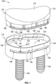
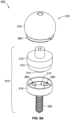
- the glenoid implant system 100 includes an anchoring structure 110 and a glenoid liner 170 (e.g., an anatomic glenoid liner).
- a glenoid liner 170 e.g., an anatomic glenoid liner
- the anchoring structure 110 includes a base 120, a wall 130, and a ledge 140.
- the wall 130 extends from a first surface 122 of the base 120.
- the wall 130 of the anchoring structure 110 extends generally perpendicularly from the first surface 122 of the base 120.
- the ledge 140 of the anchoring structure 110 extends from an inside surface of the wall 130 as opposed to an outside surface of the wall 130.
- the ledge 140 extends generally along at least a portion of a first side 132 of the wall 130, thereby forming an undercut 136.
- the transition from the ledge 140 to the undercut 136 includes a straight edge, a bevel, a chamfer, or any combination thereof.
- the wall 130 includes a slot 138 formed in a second opposing side 134 of the wall 130.
- the anchoring structure 110 can include a porous coating, for example, around the wall 130 of the anchoring structure 110.
- the porous coating can aid in osseointegration with the bone of a patient having the glenoid implant system installed and/or implanted.
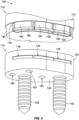
- the glenoid liner 170 includes a cap portion 172, a main body 180, and a plurality of deflectable fingers 190.
- the main body 180 extends from the second opposing surface of the cap portion 172.
- Each deflectable finger 190 also extends from the second opposing surface 176 of the cap portion 172.
- the glenoid liner 170 is one monolithic part.
- one or more components of the glenoid liner 170 is separate and distinct from the remaining components of the glenoid liner 170.
- the cap portion 172 includes a first surface 174, and a second opposing surface 176.
- the first surface 174 of the cap portion 172 is generally concave.
- the first surface 174 of the cap portion 172 is rounded and may resemble the shape of a healthy human glenoid bone.
- the second opposing surface 176 of the cap portion 172 is generally planar.
- the glenoid liner 170 is configured to be removably coupled to the anchoring structure 110. There are several components that aid in securing the glenoid liner 170 to the anchoring structure 110. First, in some implementations, the main body 180 includes a lip 186 configured to engage the undercut 136 of the anchoring structure 110.
- each deflectable finger 190 includes a protrusion 198, which is configured to engage the slot 138 of the anchoring structure 110 to aid in securing the glenoid liner 170 to the anchoring structure 110.
- the protrusion 198 of the deflectable finger 190 includes an elongated rib, a ball, a hook, or any combination thereof.
- each deflectable finger 190 is snap-locked into the corresponding slot 138 of the anchoring structure 110 via the protrusion 198.
- the glenoid liner 170 includes a plurality of snap fasteners that are configured to engage one or more of the slots 138 of the anchoring structure 110 to aid in securing the glenoid liner 170 to the anchoring structure 110.
- the ledge 140 of the anchoring structure 110 includes a first protrusion 142.
- the first protrusion 142 is configured to engage a first corresponding notch 182 formed in the main body 180 of the glenoid liner 170.
- the first corresponding notch 182 is positioned generally between the cap portion 172 of the glenoid liner 170 and the lip 186 of the main body 180 of the glenoid liner 170.
- the anchoring structure 110 further includes a second protrusion 144, which is positioned generally between the first protrusion 142 of the ledge 140 and the base 120 of the anchoring structure 110.
- the second protrusion 144 is configured to engage a second corresponding notch 184 formed in the lip 186 of the main body 180 of the glenoid liner 170 (as best shown in FIG. 3 ).
- the first protrusion 142 extends a first distance from the wall 130.
- the second protrusion 144 extends a second distance from the wall 130 that is less than the first distance. Additionally, or alternatively, in some implementations, the first protrusion 142 is stacked on the second protrusion 144 in a stepped fashion.
- a glenoid implant system of the present disclosure can include more or fewer sets of components that aid in securing the glenoid liner 170 to the anchoring structure 110.
- a first alternative glenoid implant system can include the lip 186 of the main body 180 configured to engage the undercut 136 of the anchoring structure 110; and the protrusion 198 of each deflectable finger 190 configured to engage the corresponding slot 138 of the anchoring structure 110.
- a second alternative glenoid implant system can include the protrusion 198 of each deflectable finger 190 configured to engage the corresponding slot 138 of the anchoring structure 110; the first protrusion 142 of the ledge 140 of the anchoring structure 110 configured to engage the first corresponding notch 182 formed in the main body 180 of the glenoid liner 170; and the second protrusion 144 of the anchoring structure 110 configured to engage the second corresponding notch 184 formed in the lip 186 of the main body 180 of the glenoid liner 170.
- a third alternative glenoid implant system can include the lip 186 of the main body 180 configured to engage the undercut 136 of the anchoring structure 110; the protrusion 198 of each deflectable finger 190 configured to engage the corresponding slot 138 of the anchoring structure 110; and the second protrusion 144 of the anchoring structure 110 configured to engage the second corresponding notch 184 formed in the lip 186 of the main body 180 of the glenoid liner 170.
- a fourth alternative glenoid implant system can include the lip 186 of the main body 180 configured to engage the undercut 136 of the anchoring structure 110; the protrusion 198 of each deflectable finger 190 configured to engage the corresponding slot 138 of the anchoring structure 110; and the first protrusion 142 of the ledge 140 of the anchoring structure 110 configured to engage the first corresponding notch 182 formed in the main body 180 of the glenoid liner 170.
- a fifth alternative glenoid implant system can include a dovetail locking mechanism on the first side 132 of the wall 130 that is configured to engage a mating dovetail locking mechanism on the main body 180; and the protrusion 198 of each deflectable finger 190 configured to engage the corresponding slot 138 of the anchoring structure 110.
- the base 120 of the anchoring structure 110 is generally egg shaped
- the base 120 of the anchoring structure 110 can have any suitable shapes.
- the base 120 of the anchoring structure 110 is generally circular, generally oval, generally bean shaped, generally egg shaped, generally tear-drop shaped, generally football shaped, or any combination thereof.
- the anchoring structure 110 is configured to be anchored in a glenoid cavity of a patient.
- the anchoring structure 110 further includes a first anchoring peg 150 extending from a second opposing surface 124 of the base 120 opposite the first surface 122 of the base 120 (e.g., across the base 120).
- the anchoring structure 110 can further include a second anchoring peg 152 extending from the second opposing surface 124 of the base 120, where the second anchoring peg 152 is spaced from the first anchoring peg 150. While in some implementations, only one anchoring peg is needed, having both the first anchoring peg 150 and the second anchoring peg 152 is advantageous to prevent any unwanted rotation of the anchoring structure 110 once it is installed into the patient.
- the first anchoring peg 150 and the second anchoring peg 152 are the same, and have ridges that flex when press fit into the bone (e.g., the glenoid cavity) of the patient. In some implementations, the ridges aid in the osseointegration of the anchoring peg 150 to the bone of the patient.
- the anchoring structure 110 in place of the first anchoring peg 150, includes a first screw hole for a center screw to attach the anchoring structure 110 to the bone (e.g., the glenoid cavity) of the patient.
- the anchoring structure 110 in place of the second anchoring peg 152, includes a second screw hole for a side screw to attach the anchoring structure 110 to the bone (e.g., the glenoid cavity) of the patient.
- the base 120 of the anchoring structure 110 further includes a plurality of through-holes 160 for receiving one or more respective fasteners therethrough.
- the plurality of through-holes 160 can be straight, angled, or both.
- the second opposing surface 124 of the base 120 is generally planar for coupling to a corresponding generally planar surface of the glenoid fossa of the patient.
- the generally planar second opposing surface 124 of the base 120 can be more bone-conserving, which sits on the reamed surface of the glenoid focca.
- the second opposing surface 124 of the base 120 is generally convex for coupling to a corresponding generally concave surface of the glenoid fossa of the patient.
- the glenoid liner 170 is configured to be removably coupled to the anchoring structure 110.
- Some examples of the steps for coupling the glenoid liner 170 to the anchoring structure 110 are illustrated in FIGS. 4A-7B , according to some implementations of the present disclosure.
- FIGS. 4A-4B a first step of assembling the glenoid implant system 100 is illustrated in its perspective view ( FIG. 4A ) and its cross-sectional view ( FIG. 4B ), according to some implementations of the present disclosure.
- the same reference numbers in FIGS. 4A-4B are used for the same elements in FIGS. 1-3 .
- the glenoid liner 170 is angled and/or tilted such that the lip 186 of the glenoid liner 170 is closer to the first side 132 ( FIG. 1 ) of the wall 130, than the plurality of deflectable fingers 190 is to the second opposing side 132 ( FIG. 1 ) of the wall 130.
- the first corresponding notch 182 formed in the main body 180 of the glenoid liner 170 is being aligned vertically with the first protrusion 142 of the ledge 140 of the anchoring structure 110.
- the second corresponding notch 184 formed in the lip 186 of the main body 180 of the glenoid liner 170 is being aligned vertically with the second protrusion 144 of the anchoring structure 110.
- FIGS. 5A-5B a second step of assembling the glenoid implant system 100 is illustrated in its perspective view ( FIG. 5A ) and its cross-sectional view ( FIG. 5B ), according to some implementations of the present disclosure.
- the same reference numbers in FIGS. 5A-5B are used for the same elements in FIGS. 1-3 .
- the lip 186 of the main body 180 is inserted to engage the undercut 136 of the anchoring structure 110.
- the first protrusion 142 of the ledge 140 of the anchoring structure 110 is inserted to engage the first corresponding notch 182 formed in the main body 180 of the glenoid liner 170.
- the second protrusion 144 of the anchoring structure 110 is inserted to engage the second corresponding notch 184 formed in the lip 186 of the main body 180 of the glenoid liner 170.
- the plurality of deflectable fingers 190 of the glenoid liner 170 is pushed inward and downward relative to the wall 130 of the anchoring structure 110, so that the protrusion 198 of each deflectable finger 190 can move past a portion of the wall 130 that is above the corresponding slot 138.
- FIGS. 6A-6B a third step of assembling the glenoid implant system 100 is illustrated in its perspective view ( FIG. 6A ) and its cross-sectional view ( FIG. 6B ), according to some implementations of the present disclosure.
- the same reference numbers in FIGS. 6A-6B are used for the same elements in FIGS. 1-3 .
- the lip 186 of the main body 180 is almost fully engaged with the undercut 136 of the anchoring structure 110.
- the first protrusion 142 of the ledge 140 of the anchoring structure 110 is almost fully engaged with the first corresponding notch 182 formed in the main body 180 of the glenoid liner 170.
- the second protrusion 144 of the anchoring structure 110 is almost fully engaged with the second corresponding notch 184 formed in the lip 186 of the main body 180 of the glenoid liner 170.
- each deflectable finger 190 has almost moved past the portion of the wall 130 that is above the corresponding slot 138.
- the plurality of deflectable fingers 190 of the glenoid liner 170 is further pushed downward (e.g., toward the base 120 of the anchoring structure 110), so that the plurality of deflectable fingers 190 can spring back (e.g., deflect back to its original position) to allow the protrusion 198 of each deflectable finger 190 to engage the corresponding slot 138 of the anchoring structure 110.
- FIGS. 7A-7B an assembled glenoid implant system 100 is illustrated in its perspective view ( FIG. 7A ) and its cross-sectional view ( FIG. 7B ), according to some implementations of the present disclosure.
- the same reference numbers in FIGS. 7A-7B are used for the same elements in FIGS. 1-3 .
- the lip 186 of the main body 180 is engaged with the undercut 136 of the anchoring structure 110.
- the first protrusion 142 of the ledge 140 of the anchoring structure 110 is engaged with the first corresponding notch 182 formed in the main body 180 of the glenoid liner 170.
- the second protrusion 144 of the anchoring structure 110 is also engaged with the second corresponding notch 184 formed in the lip 186 of the main body 180ff of the glenoid liner 170.
- the plurality of deflectable fingers 190 of the glenoid liner 170 has snapped down and into the corresponding slots 138 of the anchoring structure 110, and the protrusion 198 of each deflectable finger 190 is engaged with the corresponding slot 138 of the anchoring structure 110.
- the wall 130 extends about an entire perimeter of the base 120 (as best shown in FIG. 1 ). As such, when assembled, the main body 180 of the glenoid liner 170 is configured to be encapsulated within the wall 130 of the anchoring structure 110.
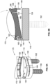
- FIGS. 8A-8B a first alternative glenoid implant system 200 is illustrated in its disassembled view of ( FIG. 8A ) and its assembled view ( FIG. 8B ), according to some implementations of the present disclosure.
- the glenoid implant system 200 is the same as, or similar to, the glenoid implant system 100, where like reference numbers are used for like elements, except that the anchoring structure 210 of the glenoid implant system 200 includes a baseplate 216 and a glenoid liner adapter 212 (e.g., an anatomic glenoid liner adapter).
- the glenoid implant system 200 can be used for TSA (e.g., an anatomic procedure).
- TSA e.g., an anatomic procedure
- the anatomic procedure can involve the repair and/or replacement of the affected extremity's ball and socket joint after years of degeneration. This surgery involves replacing the ball portion of the shoulder, which is also referred to as the humeral head, with a metal sphere while a plastic or other synthetic apparatus is used for the socket replacement. This type of procedure is most helpful for patients with arthritis and other related conditions, which result in joint problems and missing cartilage.
- the glenoid liner 270 of the glenoid implant system 200 is the same as, or similar to, the glenoid liner 170 of the glenoid implant system 100.
- the glenoid liner 270 is configured to be coupled to the glenoid liner adapter 212, in the same or similar manner as what is disclosed and illustrated with reference to FIGS. 4A-7B .
- the glenoid liner adapter 212 is configured to be coupled to the baseplate 216.
- the glenoid liner adapter 212 includes stacked protuberances 213 and 214 extending from the base 220.
- the stacked protuberances 213 and 214 are spaced from the second anchoring peg 252.
- the baseplate 216 includes a wall (e.g., a shell, a peripheral rim) 215 configured to receive the first protuberance 213.
- the coupling mechanism between the wall 215 and the first protuberance 213 includes an interference fit, a spring fit, a Morse Taper lock, or any combination thereof.
- the baseplate 216 includes a cavity 217 configured to receive the second protuberance 214.
- the coupling mechanism between the cavity 217 and the second protuberance 214 can include an interference fit, a spring fit, a Morse Taper lock, or any combination thereof.
- the glenoid liner adapter 212 is configured to be coupled to the baseplate 216 via a center screw.
- the baseplate 216 includes peripheral screw holes 260 located around the cavity 217.
- the peripheral screw holes 260 can be used for straight and/or angled screws.
- the wall 215 of the baseplate 216 provides added stability against edge loading.
- the baseplate 216 can include a porous coating, for example, around the wall 215 of the baseplate 216.
- TSA uses a metal ball component at the humeral head, which mates into a polyethylene cup on the glenoid.
- RSA switches the locations between the head and the cup, such that the humerus becomes the cup and the glenoid becomes the head.
- RSA can be performed as a revision to TSA, allowing greater functionality for patients with rotator cuff tears.
- RSA utilizes the patient's deltoid to control the movements of the shoulder.
- the revision from TSA to RSA involves the replacement of both the glenoid component and the humeral component.
- the cemented glenoid component is replaced by a metal baseplate and screws.
- the stem and the head are removed and replaced with new RSA components.
- the conversion shoulder arthroplasty corrects the failure of the TSA due to loosened implants, wear, infection, and/or shoulder dislocation or misalignment.
- the present disclosure provides for a shoulder arthroplasty implant that allows easily accessible conversion from a TSA system to a RSA system.
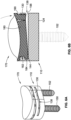
- a second alternative glenoid implant system 300 is illustrated in its disassembled view of ( FIG. 9A ) and its assembled view ( FIG. 9B ), according to some implementations of the present disclosure.
- the glenoid implant system 300 includes an anchoring structure 310 that is the same as, or similar to, the anchoring structure 210 of the glenoid implant system 200 ( FIG.
- the anchoring structure 310 of the glenoid implant system 300 includes a baseplate 316 and a glenosphere adapter 312 (e.g., a reverse glenosphere adapter).
- the glenoid implant system 300 further includes a glenosphere 370 (e.g., a reverse glenosphere) configured to be coupled to the glenosphere adapter 312.
- the glenoid implant system 300 can be used for RSA (e.g., a reverse procedure).
- RSA e.g., a reverse procedure
- reverse total shoulder replacement is a better option because the rotator cuff muscles no longer function.
- the reverse total shoulder replacement relies on the deltoid muscle, instead of the rotator cuff, to position and power the arm.
- the baseplate 316 of the glenoid implant system 300 is the same as the baseplate 216 of the glenoid implant system 200.
- the baseplate can stay in the patient, where the glenoid liner adapter 212 and the glenoid liner 270 can be replaced by the to the glenosphere adapter 312 and the glenosphere 370.
- the glenosphere 370 is configured to be coupled to the glenosphere adapter 312.
- the glenosphere adapter 312 is configured to be coupled to the baseplate 316.
- the glenosphere adapter 312 includes stacked protuberances 313 and 314.
- the baseplate 316 includes a wall (e.g., a shell, a peripheral rim) configured to receive the first protuberance 313, similar to the coupling mechanism between the wall 215 and the first protuberance 213 of the glenoid implant system 200 ( FIGS. 8A-8B ).
- the baseplate 316 includes a cavity 317 configured to receive the second protuberance 314, similar to the coupling mechanism between the cavity 217 and the second protuberance 214 of the glenoid implant system 200 ( FIGS. 8A-8B ). Additionally, or alternatively, in some implementations, the glenosphere adapter 312 is configured to be coupled to the baseplate 316 via a center screw.
- a glenoid implant assembly can include the following components: a baseplate (e.g., the baseplate 216 or the baseplate 316), a glenoid liner adapter (e.g., the glenoid liner adapter 212), a glenoid liner (e.g., the glenoid liner 170 or the glenoid liner 270), a glenosphere adapter (e.g., the glenosphere adapter 312), and a glenosphere (e.g., the glenosphere 370).
- a baseplate e.g., the baseplate 216 or the baseplate 316
- a glenoid liner adapter e.g., the glenoid liner adapter 212
- a glenoid liner e.g., the glenoid liner 170 or the glenoid liner 270
- a glenosphere adapter e.g., the gle
- RSA can be performed as a revision to TSA.
- the baseplate can remain in place during the revision to TSA, while the glenoid liner adapter and the glenoid liner can be replaed by the glenosphere adapter and the glenosphere.
Landscapes
- Health & Medical Sciences (AREA)
- Life Sciences & Earth Sciences (AREA)
- Veterinary Medicine (AREA)
- Public Health (AREA)
- Oral & Maxillofacial Surgery (AREA)
- Transplantation (AREA)
- General Health & Medical Sciences (AREA)
- Animal Behavior & Ethology (AREA)
- Engineering & Computer Science (AREA)
- Vascular Medicine (AREA)
- Heart & Thoracic Surgery (AREA)
- Biomedical Technology (AREA)
- Cardiology (AREA)
- Orthopedic Medicine & Surgery (AREA)
- Chemical & Material Sciences (AREA)
- Dispersion Chemistry (AREA)
- Dermatology (AREA)
- Medicinal Chemistry (AREA)
- Epidemiology (AREA)
- Prostheses (AREA)
Claims (15)
- Système d'implant glénoïdien comprenantune structure d'ancrage (110) comportant une base (120), une paroi (130) et un rebord (140), la paroi s'étendant à partir d'une première surface (122) de la base (120), le rebord (140) s'étendant généralement le long d'au moins une partie d'un premier côté (132) de la paroi (130) formant ainsi une contre-dépouille (136), la paroi (130) comportant une fente (138) formée dans un second côté opposé (134) de la paroi (130) ; etun revêtement glénoïde (170) configuré pour être couplé de manière amovible à la structure d'ancrage (110), le revêtement glénoïde (170) ayant une partie de capuchon (172), un corps principal (180), et un doigt déflectable (190), la partie de capuchon (172) ayant une première surface (174) et une seconde surface opposée (176), le corps principal (180) s'étendant à partir de la seconde surface opposée (176) de la partie de capuchon (172) et comprenant une lèvre (186) configurée pour s'engager dans la contre-dépouille (136) de la structure d'ancrage (110), le doigt déflecteur (190) s'étendant à partir de la deuxième surface opposée (176) de la partie capuchon (172), le doigt déflecteur (190) ayant une protubérance (198) configurée pour s'engager dans la fente (138) de la structure d'ancrage (110) afin d'aider à fixer le revêtement glénoïde (170) à la structure d'ancrage (110),dans lequel le rebord (140) de la structure d'ancrage (110) comprend une première protubérance (142) configurée pour s'engager dans une première encoche correspondante (182) formée dans le corps principal (180) du revêtement glénoïde(170), caractérisé en ce que la première protubérance (142) s'étend du premier côté (132) de la paroi (130) sur une plus grande distance qu'un reste du rebord (140).
- Le système d'implant glénoïdien de la revendication 1, dans lequel la base (120) de la structure d'ancrage (110) est généralement circulaire, généralement ovale, généralement en forme de haricot, généralement en forme d'oeuf, généralement en forme de goutte d'eau, généralement en forme de ballon de football, ou toute combinaison de celles-ci.
- Le système d'implant glénoïdien de la revendication 1, dans lequel le rebord (140) de la structure d'ancrage (110) s'étend à partir d'une surface intérieure de la paroi (130) par opposition à une surface extérieure de la paroi (130).
- Le système d'implant glénoïdien de la revendication 1, dans lequel la structure d'ancrage (110) est configurée pour être ancrée dans la cavité glénoïde d'un patient.
- Le système d'implant glénoïdien de la revendication 1, dans lequel la structure d'ancrage (110) comprend une plaque de base (216) et un adaptateur (212), et dans lequel l'adaptateur (212) est un adaptateur de revêtement glénoïdien ou un adaptateur de glénosphère.
- Le système d'implant glénoïdien de la revendication 5, comprenant en outre une glénosphère (370) configurée pour être couplée à l'adaptateur de glénosphère.
- Le système d'implant glénoïdien de la revendication 1, dans lequel la paroi (130) s'étend sur tout le périmètre de la base (120).
- Le système d'implant glénoïdien de la revendication 1, dans lequel la paroi (130) de la structure d'ancrage (110) s'étend généralement perpendiculairement à la première surface de la base (120).
- Le système d'implant glénoïdien de la revendication 1, dans lequel la structure d'ancrage (110) comprend en outre une première cheville d'ancrage (150) s'étendant à partir d'une deuxième surface opposée de la base (120) à l'opposé de la première surface de la base (120).
- Le système d'implant glénoïdien de la revendication 1, dans lequel la base (120) de la structure d'ancrage (110) comprend en outre une pluralité d'orifices traversants (160) destinés à recevoir une ou plusieurs fixations respectives afin de faciliter la fixation de la structure d'ancrage (110) à la fosse glénoïde d'un patient.
- Le système d'implant glénoïdien de la revendication 1, dans lequel la première encoche correspondante (182) est positionnée généralement entre la partie capuchon (172) du revêtement glénoïdien (170) et la lèvre (186) du corps principal du revêtement glénoïdien (170).
- Le système d'implant glénoïdien de la revendication 1, dans lequel la structure d'ancrage (110) comprend en outre une deuxième protubérance (144) configurée pour s'engager dans une deuxième encoche correspondante (184) formée dans la lèvre (186) du corps principal du revêtement glénoïdien (170).
- Le système d'implant glénoïdien de la revendication 1, dans lequel le revêtement glénoïdien (170) est une pièce monolithique.
- Le système d'implant glénoïdien de la revendication 1, dans lequel la première surface (174) de la partie capuchon (172) du revêtement glénoïdien (170) est généralement concave.
- Le système d'implant glénoïdien selon la revendication 1, dans lequel la deuxième protubérance est empilée sous la première protubérance (142), et dans lequel la deuxième protubérance (144) s'étend du premier côté (132) de la paroi (130) à une distance inférieure à celle de la première protubérance (142).
Priority Applications (1)
| Application Number | Priority Date | Filing Date | Title |
|---|---|---|---|
| EP23214620.9A EP4309630A3 (fr) | 2019-04-25 | 2020-04-24 | Systèmes d'implant glénoïde et leurs procédés d'utilisation |
Applications Claiming Priority (2)
| Application Number | Priority Date | Filing Date | Title |
|---|---|---|---|
| US201962838792P | 2019-04-25 | 2019-04-25 | |
| PCT/US2020/029932 WO2020219962A1 (fr) | 2019-04-25 | 2020-04-24 | Systèmes d'implant glénoïde et leurs méthodes d'utilisation |
Related Child Applications (2)
| Application Number | Title | Priority Date | Filing Date |
|---|---|---|---|
| EP23214620.9A Division-Into EP4309630A3 (fr) | 2019-04-25 | 2020-04-24 | Systèmes d'implant glénoïde et leurs procédés d'utilisation |
| EP23214620.9A Division EP4309630A3 (fr) | 2019-04-25 | 2020-04-24 | Systèmes d'implant glénoïde et leurs procédés d'utilisation |
Publications (3)
| Publication Number | Publication Date |
|---|---|
| EP3958795A1 EP3958795A1 (fr) | 2022-03-02 |
| EP3958795A4 EP3958795A4 (fr) | 2022-12-21 |
| EP3958795B1 true EP3958795B1 (fr) | 2024-01-17 |
Family
ID=72941372
Family Applications (2)
| Application Number | Title | Priority Date | Filing Date |
|---|---|---|---|
| EP23214620.9A Pending EP4309630A3 (fr) | 2019-04-25 | 2020-04-24 | Systèmes d'implant glénoïde et leurs procédés d'utilisation |
| EP20794900.9A Active EP3958795B1 (fr) | 2019-04-25 | 2020-04-24 | Systèmes d'implant glénoïde |
Family Applications Before (1)
| Application Number | Title | Priority Date | Filing Date |
|---|---|---|---|
| EP23214620.9A Pending EP4309630A3 (fr) | 2019-04-25 | 2020-04-24 | Systèmes d'implant glénoïde et leurs procédés d'utilisation |
Country Status (9)
| Country | Link |
|---|---|
| US (2) | US11406506B2 (fr) |
| EP (2) | EP4309630A3 (fr) |
| JP (2) | JP7384924B2 (fr) |
| KR (2) | KR102650843B1 (fr) |
| CN (1) | CN114364348A (fr) |
| AU (1) | AU2020262479A1 (fr) |
| CA (1) | CA3137291A1 (fr) |
| MX (1) | MX2021013013A (fr) |
| WO (1) | WO2020219962A1 (fr) |
Families Citing this family (3)
| Publication number | Priority date | Publication date | Assignee | Title |
|---|---|---|---|---|
| FR2971144A1 (fr) | 2011-02-08 | 2012-08-10 | Tornier Sa | Implant glenoidien pour prothese d'epaule et kit chirurgical |
| AU2020328486B2 (en) | 2019-08-09 | 2024-01-25 | Howmedica Osteonics Corp. | Apparatuses and methods for implanting glenoid prostheses |
| AU2022398690A1 (en) * | 2021-11-29 | 2024-05-09 | Howmedica Osteonics Corp. | Convertible glenoid implants |
Family Cites Families (15)
| Publication number | Priority date | Publication date | Assignee | Title |
|---|---|---|---|---|
| US4550450A (en) * | 1984-07-24 | 1985-11-05 | Kinnett James G | Total shoulder prosthesis system |
| US4964865A (en) * | 1988-02-03 | 1990-10-23 | Intermedics Orthopedics, Inc. | Glenoid prosthesis and method of use |
| US6228119B1 (en) * | 1998-06-09 | 2001-05-08 | Depuy Orthopaedics, Inc. | Modular glenoid assembly |
| US6679916B1 (en) | 2002-04-29 | 2004-01-20 | Mark A. Frankle | Shoulder prosthesis system |
| US8070820B2 (en) * | 2003-10-08 | 2011-12-06 | Biomet Manufacturing Corp. | Shoulder implant assembly |
| US20060200248A1 (en) * | 2005-03-03 | 2006-09-07 | Laurent Beguin | Prosthesis for the glenoid cavity of the scapula |
| WO2007031575A1 (fr) * | 2005-09-16 | 2007-03-22 | Zimmer Gmbh | Plateau et coquille d'un dispositif de reception d'une rotule |
| ITUD20050185A1 (it) * | 2005-11-03 | 2007-05-04 | Lima Lto Spa | Elemento di fissaggio aggiuntivo per una protesi per l' articolazione della spalla |
| WO2007084939A2 (fr) | 2006-01-20 | 2007-07-26 | Zimmer Technology, Inc. | Système pour arthroplastie de l'épaule |
| EP2604224A1 (fr) * | 2011-10-31 | 2013-06-19 | Tornier Orthopedics Ireland Ltd. | Prothèse d'épaule réversible modulaire |
| WO2013096399A1 (fr) * | 2011-12-19 | 2013-06-27 | Smith & Nephew, Inc. | Systèmes d'insert orthopédique et procédés associés |
| EP3340937B1 (fr) | 2015-08-27 | 2024-03-20 | Zimmer, Inc. | Systèmes et prothèses d'épaule inversée à verrouillage directionnel |
| EP3503850B1 (fr) * | 2016-08-24 | 2022-04-13 | Greiwe, Raymond Michael | Système d'implant de tête humérale |
| AU2019351889B2 (en) * | 2018-10-02 | 2022-02-03 | Howmedica Osteonics Corp. | Modular humeral head |
| JP7275256B2 (ja) * | 2018-10-02 | 2023-05-17 | ハウメディカ オステオニクス コーポレイション | 肩プロテーゼの構成要素及びアセンブリ |
-
2020
- 2020-04-24 US US17/594,571 patent/US11406506B2/en active Active
- 2020-04-24 KR KR1020217034965A patent/KR102650843B1/ko active IP Right Grant
- 2020-04-24 KR KR1020247009060A patent/KR20240039233A/ko active Application Filing
- 2020-04-24 EP EP23214620.9A patent/EP4309630A3/fr active Pending
- 2020-04-24 MX MX2021013013A patent/MX2021013013A/es unknown
- 2020-04-24 JP JP2021563250A patent/JP7384924B2/ja active Active
- 2020-04-24 WO PCT/US2020/029932 patent/WO2020219962A1/fr unknown
- 2020-04-24 CN CN202080030683.9A patent/CN114364348A/zh active Pending
- 2020-04-24 EP EP20794900.9A patent/EP3958795B1/fr active Active
- 2020-04-24 AU AU2020262479A patent/AU2020262479A1/en active Pending
- 2020-04-24 CA CA3137291A patent/CA3137291A1/fr active Pending
-
2022
- 2022-07-07 US US17/859,905 patent/US20220338999A1/en active Pending
-
2023
- 2023-11-09 JP JP2023191263A patent/JP2023184706A/ja active Pending
Also Published As
| Publication number | Publication date |
|---|---|
| US20220142789A1 (en) | 2022-05-12 |
| AU2020262479A1 (en) | 2021-12-23 |
| JP7384924B2 (ja) | 2023-11-21 |
| KR20220002330A (ko) | 2022-01-06 |
| EP3958795A4 (fr) | 2022-12-21 |
| CN114364348A (zh) | 2022-04-15 |
| JP2023184706A (ja) | 2023-12-28 |
| EP4309630A3 (fr) | 2024-03-27 |
| US11406506B2 (en) | 2022-08-09 |
| KR20240039233A (ko) | 2024-03-26 |
| CA3137291A1 (fr) | 2020-10-29 |
| KR102650843B1 (ko) | 2024-03-22 |
| MX2021013013A (es) | 2021-12-10 |
| JP2022529537A (ja) | 2022-06-22 |
| EP4309630A2 (fr) | 2024-01-24 |
| US20220338999A1 (en) | 2022-10-27 |
| WO2020219962A1 (fr) | 2020-10-29 |
| EP3958795A1 (fr) | 2022-03-02 |
Similar Documents
| Publication | Publication Date | Title |
|---|---|---|
| US20220338999A1 (en) | Glenoid implant systems and methods of using the same | |
| US11471292B2 (en) | Augment insert, shoulder prosthesis and kit comprising the augment insert | |
| US9283083B2 (en) | Shoulder implant assembly | |
| EP3280360B1 (fr) | Implant glénoïde convertible | |
| EP1427357B1 (fr) | Tete d'humerus modulaire a connecteur excentrique | |
| US20050278033A1 (en) | Total shoulder prosthesis or inverted type | |
| US20060111787A1 (en) | Glenoid prosthesis and method of implanting same | |
| US20200188124A1 (en) | Implants, systems and methods of using the same | |
| US20240216143A1 (en) | Modular Glenoid Component for Use in a Universal Shoulder Prosthesis System | |
| US20230027395A1 (en) | Anchoring member for a joint replacement | |
| WO2023097324A1 (fr) | Implants glénoïdiens convertibles | |
| CN115551445A (zh) | 肩部假体 | |
| WO2024020216A1 (fr) | Composants destinés à être utilisés dans un système de prothèse d'épaule universel |
Legal Events
| Date | Code | Title | Description |
|---|---|---|---|
| STAA | Information on the status of an ep patent application or granted ep patent |
Free format text: STATUS: THE INTERNATIONAL PUBLICATION HAS BEEN MADE |
|
| PUAI | Public reference made under article 153(3) epc to a published international application that has entered the european phase |
Free format text: ORIGINAL CODE: 0009012 |
|
| STAA | Information on the status of an ep patent application or granted ep patent |
Free format text: STATUS: REQUEST FOR EXAMINATION WAS MADE |
|
| 17P | Request for examination filed |
Effective date: 20211117 |
|
| AK | Designated contracting states |
Kind code of ref document: A1 Designated state(s): AL AT BE BG CH CY CZ DE DK EE ES FI FR GB GR HR HU IE IS IT LI LT LU LV MC MK MT NL NO PL PT RO RS SE SI SK SM TR |
|
| DAV | Request for validation of the european patent (deleted) | ||
| DAX | Request for extension of the european patent (deleted) | ||
| A4 | Supplementary search report drawn up and despatched |
Effective date: 20221123 |
|
| RIC1 | Information provided on ipc code assigned before grant |
Ipc: A61F 2/30 20060101ALI20221117BHEP Ipc: A61F 2/40 20060101AFI20221117BHEP |
|
| GRAP | Despatch of communication of intention to grant a patent |
Free format text: ORIGINAL CODE: EPIDOSNIGR1 |
|
| STAA | Information on the status of an ep patent application or granted ep patent |
Free format text: STATUS: GRANT OF PATENT IS INTENDED |
|
| INTG | Intention to grant announced |
Effective date: 20231108 |
|
| GRAS | Grant fee paid |
Free format text: ORIGINAL CODE: EPIDOSNIGR3 |
|
| GRAA | (expected) grant |
Free format text: ORIGINAL CODE: 0009210 |
|
| STAA | Information on the status of an ep patent application or granted ep patent |
Free format text: STATUS: THE PATENT HAS BEEN GRANTED |
|
| AK | Designated contracting states |
Kind code of ref document: B1 Designated state(s): AL AT BE BG CH CY CZ DE DK EE ES FI FR GB GR HR HU IE IS IT LI LT LU LV MC MK MT NL NO PL PT RO RS SE SI SK SM TR |
|
| REG | Reference to a national code |
Ref country code: GB Ref legal event code: FG4D |
|
| REG | Reference to a national code |
Ref country code: DE Ref legal event code: R096 Ref document number: 602020024565 Country of ref document: DE |
|
| REG | Reference to a national code |
Ref country code: CH Ref legal event code: EP |
|
| REG | Reference to a national code |
Ref country code: IE Ref legal event code: FG4D |
|
| REG | Reference to a national code |
Ref country code: LT Ref legal event code: MG9D |
|
| REG | Reference to a national code |
Ref country code: NL Ref legal event code: MP Effective date: 20240117 |
|
| REG | Reference to a national code |
Ref country code: AT Ref legal event code: MK05 Ref document number: 1650058 Country of ref document: AT Kind code of ref document: T Effective date: 20240117 |
|
| PG25 | Lapsed in a contracting state [announced via postgrant information from national office to epo] |
Ref country code: NL Free format text: LAPSE BECAUSE OF FAILURE TO SUBMIT A TRANSLATION OF THE DESCRIPTION OR TO PAY THE FEE WITHIN THE PRESCRIBED TIME-LIMIT Effective date: 20240117 |
|
| PG25 | Lapsed in a contracting state [announced via postgrant information from national office to epo] |
Ref country code: NL Free format text: LAPSE BECAUSE OF FAILURE TO SUBMIT A TRANSLATION OF THE DESCRIPTION OR TO PAY THE FEE WITHIN THE PRESCRIBED TIME-LIMIT Effective date: 20240117 |
|
| PG25 | Lapsed in a contracting state [announced via postgrant information from national office to epo] |
Ref country code: IS Free format text: LAPSE BECAUSE OF FAILURE TO SUBMIT A TRANSLATION OF THE DESCRIPTION OR TO PAY THE FEE WITHIN THE PRESCRIBED TIME-LIMIT Effective date: 20240517 |
|
| PGFP | Annual fee paid to national office [announced via postgrant information from national office to epo] |
Ref country code: GB Payment date: 20240429 Year of fee payment: 5 |
|
| PG25 | Lapsed in a contracting state [announced via postgrant information from national office to epo] |
Ref country code: LT Free format text: LAPSE BECAUSE OF FAILURE TO SUBMIT A TRANSLATION OF THE DESCRIPTION OR TO PAY THE FEE WITHIN THE PRESCRIBED TIME-LIMIT Effective date: 20240117 |
|
| PGFP | Annual fee paid to national office [announced via postgrant information from national office to epo] |
Ref country code: DE Payment date: 20240429 Year of fee payment: 5 |
|
| PG25 | Lapsed in a contracting state [announced via postgrant information from national office to epo] |
Ref country code: GR Free format text: LAPSE BECAUSE OF FAILURE TO SUBMIT A TRANSLATION OF THE DESCRIPTION OR TO PAY THE FEE WITHIN THE PRESCRIBED TIME-LIMIT Effective date: 20240418 |
|
| PG25 | Lapsed in a contracting state [announced via postgrant information from national office to epo] |
Ref country code: HR Free format text: LAPSE BECAUSE OF FAILURE TO SUBMIT A TRANSLATION OF THE DESCRIPTION OR TO PAY THE FEE WITHIN THE PRESCRIBED TIME-LIMIT Effective date: 20240117 Ref country code: RS Free format text: LAPSE BECAUSE OF FAILURE TO SUBMIT A TRANSLATION OF THE DESCRIPTION OR TO PAY THE FEE WITHIN THE PRESCRIBED TIME-LIMIT Effective date: 20240417 |
|
| PGFP | Annual fee paid to national office [announced via postgrant information from national office to epo] |
Ref country code: CH Payment date: 20240501 Year of fee payment: 5 |
|
| PGFP | Annual fee paid to national office [announced via postgrant information from national office to epo] |
Ref country code: ES Payment date: 20240503 Year of fee payment: 5 |
|
| PG25 | Lapsed in a contracting state [announced via postgrant information from national office to epo] |
Ref country code: AT Free format text: LAPSE BECAUSE OF FAILURE TO SUBMIT A TRANSLATION OF THE DESCRIPTION OR TO PAY THE FEE WITHIN THE PRESCRIBED TIME-LIMIT Effective date: 20240117 |
|
| PG25 | Lapsed in a contracting state [announced via postgrant information from national office to epo] |
Ref country code: RS Free format text: LAPSE BECAUSE OF FAILURE TO SUBMIT A TRANSLATION OF THE DESCRIPTION OR TO PAY THE FEE WITHIN THE PRESCRIBED TIME-LIMIT Effective date: 20240417 Ref country code: NO Free format text: LAPSE BECAUSE OF FAILURE TO SUBMIT A TRANSLATION OF THE DESCRIPTION OR TO PAY THE FEE WITHIN THE PRESCRIBED TIME-LIMIT Effective date: 20240417 Ref country code: LT Free format text: LAPSE BECAUSE OF FAILURE TO SUBMIT A TRANSLATION OF THE DESCRIPTION OR TO PAY THE FEE WITHIN THE PRESCRIBED TIME-LIMIT Effective date: 20240117 Ref country code: IS Free format text: LAPSE BECAUSE OF FAILURE TO SUBMIT A TRANSLATION OF THE DESCRIPTION OR TO PAY THE FEE WITHIN THE PRESCRIBED TIME-LIMIT Effective date: 20240517 Ref country code: HR Free format text: LAPSE BECAUSE OF FAILURE TO SUBMIT A TRANSLATION OF THE DESCRIPTION OR TO PAY THE FEE WITHIN THE PRESCRIBED TIME-LIMIT Effective date: 20240117 Ref country code: GR Free format text: LAPSE BECAUSE OF FAILURE TO SUBMIT A TRANSLATION OF THE DESCRIPTION OR TO PAY THE FEE WITHIN THE PRESCRIBED TIME-LIMIT Effective date: 20240418 Ref country code: FI Free format text: LAPSE BECAUSE OF FAILURE TO SUBMIT A TRANSLATION OF THE DESCRIPTION OR TO PAY THE FEE WITHIN THE PRESCRIBED TIME-LIMIT Effective date: 20240117 Ref country code: BG Free format text: LAPSE BECAUSE OF FAILURE TO SUBMIT A TRANSLATION OF THE DESCRIPTION OR TO PAY THE FEE WITHIN THE PRESCRIBED TIME-LIMIT Effective date: 20240117 Ref country code: AT Free format text: LAPSE BECAUSE OF FAILURE TO SUBMIT A TRANSLATION OF THE DESCRIPTION OR TO PAY THE FEE WITHIN THE PRESCRIBED TIME-LIMIT Effective date: 20240117 |
|
| PGFP | Annual fee paid to national office [announced via postgrant information from national office to epo] |
Ref country code: FR Payment date: 20240425 Year of fee payment: 5 |
|
| PG25 | Lapsed in a contracting state [announced via postgrant information from national office to epo] |
Ref country code: PL Free format text: LAPSE BECAUSE OF FAILURE TO SUBMIT A TRANSLATION OF THE DESCRIPTION OR TO PAY THE FEE WITHIN THE PRESCRIBED TIME-LIMIT Effective date: 20240117 Ref country code: PT Free format text: LAPSE BECAUSE OF FAILURE TO SUBMIT A TRANSLATION OF THE DESCRIPTION OR TO PAY THE FEE WITHIN THE PRESCRIBED TIME-LIMIT Effective date: 20240517 |
|
| PG25 | Lapsed in a contracting state [announced via postgrant information from national office to epo] |
Ref country code: SE Free format text: LAPSE BECAUSE OF FAILURE TO SUBMIT A TRANSLATION OF THE DESCRIPTION OR TO PAY THE FEE WITHIN THE PRESCRIBED TIME-LIMIT Effective date: 20240117 Ref country code: PT Free format text: LAPSE BECAUSE OF FAILURE TO SUBMIT A TRANSLATION OF THE DESCRIPTION OR TO PAY THE FEE WITHIN THE PRESCRIBED TIME-LIMIT Effective date: 20240517 Ref country code: PL Free format text: LAPSE BECAUSE OF FAILURE TO SUBMIT A TRANSLATION OF THE DESCRIPTION OR TO PAY THE FEE WITHIN THE PRESCRIBED TIME-LIMIT Effective date: 20240117 Ref country code: LV Free format text: LAPSE BECAUSE OF FAILURE TO SUBMIT A TRANSLATION OF THE DESCRIPTION OR TO PAY THE FEE WITHIN THE PRESCRIBED TIME-LIMIT Effective date: 20240117 |
|
| REG | Reference to a national code |
Ref country code: ES Ref legal event code: FG2A Ref document number: 2978726 Country of ref document: ES Kind code of ref document: T3 Effective date: 20240918 |