EP3340937B1 - Systèmes et prothèses d'épaule inversée à verrouillage directionnel - Google Patents
Systèmes et prothèses d'épaule inversée à verrouillage directionnel Download PDFInfo
- Publication number
- EP3340937B1 EP3340937B1 EP16760332.3A EP16760332A EP3340937B1 EP 3340937 B1 EP3340937 B1 EP 3340937B1 EP 16760332 A EP16760332 A EP 16760332A EP 3340937 B1 EP3340937 B1 EP 3340937B1
- Authority
- EP
- European Patent Office
- Prior art keywords
- medial
- tray
- lateral
- liner
- groove
- Prior art date
- Legal status (The legal status is an assumption and is not a legal conclusion. Google has not performed a legal analysis and makes no representation as to the accuracy of the status listed.)
- Active
Links
- 238000005259 measurement Methods 0.000 claims description 5
- 230000007246 mechanism Effects 0.000 description 18
- 238000000034 method Methods 0.000 description 10
- 238000013461 design Methods 0.000 description 5
- 230000000694 effects Effects 0.000 description 5
- 238000011882 arthroplasty Methods 0.000 description 4
- 238000013031 physical testing Methods 0.000 description 4
- 238000006243 chemical reaction Methods 0.000 description 3
- 239000007943 implant Substances 0.000 description 3
- 239000002184 metal Substances 0.000 description 3
- 238000012986 modification Methods 0.000 description 3
- 230000004048 modification Effects 0.000 description 3
- 210000003205 muscle Anatomy 0.000 description 3
- 210000000513 rotator cuff Anatomy 0.000 description 3
- 238000001356 surgical procedure Methods 0.000 description 3
- 238000012360 testing method Methods 0.000 description 3
- GVJHHUAWPYXKBD-UHFFFAOYSA-N (±)-α-Tocopherol Chemical compound OC1=C(C)C(C)=C2OC(CCCC(C)CCCC(C)CCCC(C)C)(C)CCC2=C1C GVJHHUAWPYXKBD-UHFFFAOYSA-N 0.000 description 2
- 239000004698 Polyethylene Substances 0.000 description 2
- 239000004699 Ultra-high molecular weight polyethylene Substances 0.000 description 2
- 238000010494 dissociation reaction Methods 0.000 description 2
- 230000005593 dissociations Effects 0.000 description 2
- 238000002513 implantation Methods 0.000 description 2
- 230000007935 neutral effect Effects 0.000 description 2
- -1 polyethylene Polymers 0.000 description 2
- 229920000573 polyethylene Polymers 0.000 description 2
- 229920000785 ultra high molecular weight polyethylene Polymers 0.000 description 2
- 238000000692 Student's t-test Methods 0.000 description 1
- 229920010741 Ultra High Molecular Weight Polyethylene (UHMWPE) Polymers 0.000 description 1
- 229930003427 Vitamin E Natural products 0.000 description 1
- 230000004913 activation Effects 0.000 description 1
- 238000007792 addition Methods 0.000 description 1
- 230000002411 adverse Effects 0.000 description 1
- 210000000988 bone and bone Anatomy 0.000 description 1
- 230000007812 deficiency Effects 0.000 description 1
- 230000002950 deficient Effects 0.000 description 1
- 210000000852 deltoid muscle Anatomy 0.000 description 1
- 238000006073 displacement reaction Methods 0.000 description 1
- 238000011156 evaluation Methods 0.000 description 1
- WIGCFUFOHFEKBI-UHFFFAOYSA-N gamma-tocopherol Natural products CC(C)CCCC(C)CCCC(C)CCCC1CCC2C(C)C(O)C(C)C(C)C2O1 WIGCFUFOHFEKBI-UHFFFAOYSA-N 0.000 description 1
- 238000003780 insertion Methods 0.000 description 1
- 230000037431 insertion Effects 0.000 description 1
- 230000009021 linear effect Effects 0.000 description 1
- 230000009022 nonlinear effect Effects 0.000 description 1
- 239000002574 poison Substances 0.000 description 1
- 231100000614 poison Toxicity 0.000 description 1
- 210000001991 scapula Anatomy 0.000 description 1
- 125000006850 spacer group Chemical group 0.000 description 1
- 238000006467 substitution reaction Methods 0.000 description 1
- 238000012353 t test Methods 0.000 description 1
- 229940046009 vitamin E Drugs 0.000 description 1
- 235000019165 vitamin E Nutrition 0.000 description 1
- 239000011709 vitamin E Substances 0.000 description 1
- XLYOFNOQVPJJNP-UHFFFAOYSA-N water Chemical compound O XLYOFNOQVPJJNP-UHFFFAOYSA-N 0.000 description 1
Images

Classifications
-
- A—HUMAN NECESSITIES
- A61—MEDICAL OR VETERINARY SCIENCE; HYGIENE
- A61F—FILTERS IMPLANTABLE INTO BLOOD VESSELS; PROSTHESES; DEVICES PROVIDING PATENCY TO, OR PREVENTING COLLAPSING OF, TUBULAR STRUCTURES OF THE BODY, e.g. STENTS; ORTHOPAEDIC, NURSING OR CONTRACEPTIVE DEVICES; FOMENTATION; TREATMENT OR PROTECTION OF EYES OR EARS; BANDAGES, DRESSINGS OR ABSORBENT PADS; FIRST-AID KITS
- A61F2/00—Filters implantable into blood vessels; Prostheses, i.e. artificial substitutes or replacements for parts of the body; Appliances for connecting them with the body; Devices providing patency to, or preventing collapsing of, tubular structures of the body, e.g. stents
- A61F2/02—Prostheses implantable into the body
- A61F2/30—Joints
- A61F2/40—Joints for shoulders
- A61F2/4014—Humeral heads or necks; Connections of endoprosthetic heads or necks to endoprosthetic humeral shafts
-
- A—HUMAN NECESSITIES
- A61—MEDICAL OR VETERINARY SCIENCE; HYGIENE
- A61F—FILTERS IMPLANTABLE INTO BLOOD VESSELS; PROSTHESES; DEVICES PROVIDING PATENCY TO, OR PREVENTING COLLAPSING OF, TUBULAR STRUCTURES OF THE BODY, e.g. STENTS; ORTHOPAEDIC, NURSING OR CONTRACEPTIVE DEVICES; FOMENTATION; TREATMENT OR PROTECTION OF EYES OR EARS; BANDAGES, DRESSINGS OR ABSORBENT PADS; FIRST-AID KITS
- A61F2/00—Filters implantable into blood vessels; Prostheses, i.e. artificial substitutes or replacements for parts of the body; Appliances for connecting them with the body; Devices providing patency to, or preventing collapsing of, tubular structures of the body, e.g. stents
- A61F2/02—Prostheses implantable into the body
- A61F2/30—Joints
- A61F2/40—Joints for shoulders
- A61F2/4081—Glenoid components, e.g. cups
-
- A—HUMAN NECESSITIES
- A61—MEDICAL OR VETERINARY SCIENCE; HYGIENE
- A61F—FILTERS IMPLANTABLE INTO BLOOD VESSELS; PROSTHESES; DEVICES PROVIDING PATENCY TO, OR PREVENTING COLLAPSING OF, TUBULAR STRUCTURES OF THE BODY, e.g. STENTS; ORTHOPAEDIC, NURSING OR CONTRACEPTIVE DEVICES; FOMENTATION; TREATMENT OR PROTECTION OF EYES OR EARS; BANDAGES, DRESSINGS OR ABSORBENT PADS; FIRST-AID KITS
- A61F2/00—Filters implantable into blood vessels; Prostheses, i.e. artificial substitutes or replacements for parts of the body; Appliances for connecting them with the body; Devices providing patency to, or preventing collapsing of, tubular structures of the body, e.g. stents
- A61F2/02—Prostheses implantable into the body
- A61F2/30—Joints
- A61F2002/30001—Additional features of subject-matter classified in A61F2/28, A61F2/30 and subgroups thereof
- A61F2002/30316—The prosthesis having different structural features at different locations within the same prosthesis; Connections between prosthetic parts; Special structural features of bone or joint prostheses not otherwise provided for
- A61F2002/30329—Connections or couplings between prosthetic parts, e.g. between modular parts; Connecting elements
- A61F2002/30331—Connections or couplings between prosthetic parts, e.g. between modular parts; Connecting elements made by longitudinally pushing a protrusion into a complementarily-shaped recess, e.g. held by friction fit
-
- A—HUMAN NECESSITIES
- A61—MEDICAL OR VETERINARY SCIENCE; HYGIENE
- A61F—FILTERS IMPLANTABLE INTO BLOOD VESSELS; PROSTHESES; DEVICES PROVIDING PATENCY TO, OR PREVENTING COLLAPSING OF, TUBULAR STRUCTURES OF THE BODY, e.g. STENTS; ORTHOPAEDIC, NURSING OR CONTRACEPTIVE DEVICES; FOMENTATION; TREATMENT OR PROTECTION OF EYES OR EARS; BANDAGES, DRESSINGS OR ABSORBENT PADS; FIRST-AID KITS
- A61F2/00—Filters implantable into blood vessels; Prostheses, i.e. artificial substitutes or replacements for parts of the body; Appliances for connecting them with the body; Devices providing patency to, or preventing collapsing of, tubular structures of the body, e.g. stents
- A61F2/02—Prostheses implantable into the body
- A61F2/30—Joints
- A61F2002/30001—Additional features of subject-matter classified in A61F2/28, A61F2/30 and subgroups thereof
- A61F2002/30316—The prosthesis having different structural features at different locations within the same prosthesis; Connections between prosthetic parts; Special structural features of bone or joint prostheses not otherwise provided for
- A61F2002/30329—Connections or couplings between prosthetic parts, e.g. between modular parts; Connecting elements
- A61F2002/30383—Connections or couplings between prosthetic parts, e.g. between modular parts; Connecting elements made by laterally inserting a protrusion, e.g. a rib into a complementarily-shaped groove
-
- A—HUMAN NECESSITIES
- A61—MEDICAL OR VETERINARY SCIENCE; HYGIENE
- A61F—FILTERS IMPLANTABLE INTO BLOOD VESSELS; PROSTHESES; DEVICES PROVIDING PATENCY TO, OR PREVENTING COLLAPSING OF, TUBULAR STRUCTURES OF THE BODY, e.g. STENTS; ORTHOPAEDIC, NURSING OR CONTRACEPTIVE DEVICES; FOMENTATION; TREATMENT OR PROTECTION OF EYES OR EARS; BANDAGES, DRESSINGS OR ABSORBENT PADS; FIRST-AID KITS
- A61F2/00—Filters implantable into blood vessels; Prostheses, i.e. artificial substitutes or replacements for parts of the body; Appliances for connecting them with the body; Devices providing patency to, or preventing collapsing of, tubular structures of the body, e.g. stents
- A61F2/02—Prostheses implantable into the body
- A61F2/30—Joints
- A61F2002/30001—Additional features of subject-matter classified in A61F2/28, A61F2/30 and subgroups thereof
- A61F2002/30316—The prosthesis having different structural features at different locations within the same prosthesis; Connections between prosthetic parts; Special structural features of bone or joint prostheses not otherwise provided for
- A61F2002/30329—Connections or couplings between prosthetic parts, e.g. between modular parts; Connecting elements
- A61F2002/30476—Connections or couplings between prosthetic parts, e.g. between modular parts; Connecting elements locked by an additional locking mechanism
- A61F2002/305—Snap connection
-
- A—HUMAN NECESSITIES
- A61—MEDICAL OR VETERINARY SCIENCE; HYGIENE
- A61F—FILTERS IMPLANTABLE INTO BLOOD VESSELS; PROSTHESES; DEVICES PROVIDING PATENCY TO, OR PREVENTING COLLAPSING OF, TUBULAR STRUCTURES OF THE BODY, e.g. STENTS; ORTHOPAEDIC, NURSING OR CONTRACEPTIVE DEVICES; FOMENTATION; TREATMENT OR PROTECTION OF EYES OR EARS; BANDAGES, DRESSINGS OR ABSORBENT PADS; FIRST-AID KITS
- A61F2/00—Filters implantable into blood vessels; Prostheses, i.e. artificial substitutes or replacements for parts of the body; Appliances for connecting them with the body; Devices providing patency to, or preventing collapsing of, tubular structures of the body, e.g. stents
- A61F2/02—Prostheses implantable into the body
- A61F2/30—Joints
- A61F2002/30001—Additional features of subject-matter classified in A61F2/28, A61F2/30 and subgroups thereof
- A61F2002/30316—The prosthesis having different structural features at different locations within the same prosthesis; Connections between prosthetic parts; Special structural features of bone or joint prostheses not otherwise provided for
- A61F2002/30329—Connections or couplings between prosthetic parts, e.g. between modular parts; Connecting elements
- A61F2002/30518—Connections or couplings between prosthetic parts, e.g. between modular parts; Connecting elements with possibility of relative movement between the prosthetic parts
- A61F2002/3052—Connections or couplings between prosthetic parts, e.g. between modular parts; Connecting elements with possibility of relative movement between the prosthetic parts unrestrained in only one direction, e.g. moving unidirectionally
- A61F2002/30522—Connections or couplings between prosthetic parts, e.g. between modular parts; Connecting elements with possibility of relative movement between the prosthetic parts unrestrained in only one direction, e.g. moving unidirectionally releasable, e.g. using a releasable ratchet
-
- A—HUMAN NECESSITIES
- A61—MEDICAL OR VETERINARY SCIENCE; HYGIENE
- A61F—FILTERS IMPLANTABLE INTO BLOOD VESSELS; PROSTHESES; DEVICES PROVIDING PATENCY TO, OR PREVENTING COLLAPSING OF, TUBULAR STRUCTURES OF THE BODY, e.g. STENTS; ORTHOPAEDIC, NURSING OR CONTRACEPTIVE DEVICES; FOMENTATION; TREATMENT OR PROTECTION OF EYES OR EARS; BANDAGES, DRESSINGS OR ABSORBENT PADS; FIRST-AID KITS
- A61F2/00—Filters implantable into blood vessels; Prostheses, i.e. artificial substitutes or replacements for parts of the body; Appliances for connecting them with the body; Devices providing patency to, or preventing collapsing of, tubular structures of the body, e.g. stents
- A61F2/02—Prostheses implantable into the body
- A61F2/30—Joints
- A61F2002/30001—Additional features of subject-matter classified in A61F2/28, A61F2/30 and subgroups thereof
- A61F2002/30316—The prosthesis having different structural features at different locations within the same prosthesis; Connections between prosthetic parts; Special structural features of bone or joint prostheses not otherwise provided for
- A61F2002/30535—Special structural features of bone or joint prostheses not otherwise provided for
- A61F2002/30537—Special structural features of bone or joint prostheses not otherwise provided for adjustable
- A61F2002/30538—Special structural features of bone or joint prostheses not otherwise provided for adjustable for adjusting angular orientation
- A61F2002/3054—Special structural features of bone or joint prostheses not otherwise provided for adjustable for adjusting angular orientation about a connection axis or implantation axis for selecting any one of a plurality of radial orientations between two modular parts, e.g. Morse taper connections, at discrete positions, angular positions or continuous positions
-
- A—HUMAN NECESSITIES
- A61—MEDICAL OR VETERINARY SCIENCE; HYGIENE
- A61F—FILTERS IMPLANTABLE INTO BLOOD VESSELS; PROSTHESES; DEVICES PROVIDING PATENCY TO, OR PREVENTING COLLAPSING OF, TUBULAR STRUCTURES OF THE BODY, e.g. STENTS; ORTHOPAEDIC, NURSING OR CONTRACEPTIVE DEVICES; FOMENTATION; TREATMENT OR PROTECTION OF EYES OR EARS; BANDAGES, DRESSINGS OR ABSORBENT PADS; FIRST-AID KITS
- A61F2/00—Filters implantable into blood vessels; Prostheses, i.e. artificial substitutes or replacements for parts of the body; Appliances for connecting them with the body; Devices providing patency to, or preventing collapsing of, tubular structures of the body, e.g. stents
- A61F2/02—Prostheses implantable into the body
- A61F2/30—Joints
- A61F2002/30001—Additional features of subject-matter classified in A61F2/28, A61F2/30 and subgroups thereof
- A61F2002/30621—Features concerning the anatomical functioning or articulation of the prosthetic joint
- A61F2002/30649—Ball-and-socket joints
-
- A—HUMAN NECESSITIES
- A61—MEDICAL OR VETERINARY SCIENCE; HYGIENE
- A61F—FILTERS IMPLANTABLE INTO BLOOD VESSELS; PROSTHESES; DEVICES PROVIDING PATENCY TO, OR PREVENTING COLLAPSING OF, TUBULAR STRUCTURES OF THE BODY, e.g. STENTS; ORTHOPAEDIC, NURSING OR CONTRACEPTIVE DEVICES; FOMENTATION; TREATMENT OR PROTECTION OF EYES OR EARS; BANDAGES, DRESSINGS OR ABSORBENT PADS; FIRST-AID KITS
- A61F2/00—Filters implantable into blood vessels; Prostheses, i.e. artificial substitutes or replacements for parts of the body; Appliances for connecting them with the body; Devices providing patency to, or preventing collapsing of, tubular structures of the body, e.g. stents
- A61F2/02—Prostheses implantable into the body
- A61F2/30—Joints
- A61F2/40—Joints for shoulders
- A61F2/4014—Humeral heads or necks; Connections of endoprosthetic heads or necks to endoprosthetic humeral shafts
- A61F2002/4018—Heads or epiphyseal parts of humerus
- A61F2002/4022—Heads or epiphyseal parts of humerus having a concave shape, e.g. hemispherical cups
-
- A—HUMAN NECESSITIES
- A61—MEDICAL OR VETERINARY SCIENCE; HYGIENE
- A61F—FILTERS IMPLANTABLE INTO BLOOD VESSELS; PROSTHESES; DEVICES PROVIDING PATENCY TO, OR PREVENTING COLLAPSING OF, TUBULAR STRUCTURES OF THE BODY, e.g. STENTS; ORTHOPAEDIC, NURSING OR CONTRACEPTIVE DEVICES; FOMENTATION; TREATMENT OR PROTECTION OF EYES OR EARS; BANDAGES, DRESSINGS OR ABSORBENT PADS; FIRST-AID KITS
- A61F2/00—Filters implantable into blood vessels; Prostheses, i.e. artificial substitutes or replacements for parts of the body; Appliances for connecting them with the body; Devices providing patency to, or preventing collapsing of, tubular structures of the body, e.g. stents
- A61F2/02—Prostheses implantable into the body
- A61F2/30—Joints
- A61F2/40—Joints for shoulders
- A61F2/4014—Humeral heads or necks; Connections of endoprosthetic heads or necks to endoprosthetic humeral shafts
- A61F2002/4037—Connections of heads to necks
-
- A—HUMAN NECESSITIES
- A61—MEDICAL OR VETERINARY SCIENCE; HYGIENE
- A61F—FILTERS IMPLANTABLE INTO BLOOD VESSELS; PROSTHESES; DEVICES PROVIDING PATENCY TO, OR PREVENTING COLLAPSING OF, TUBULAR STRUCTURES OF THE BODY, e.g. STENTS; ORTHOPAEDIC, NURSING OR CONTRACEPTIVE DEVICES; FOMENTATION; TREATMENT OR PROTECTION OF EYES OR EARS; BANDAGES, DRESSINGS OR ABSORBENT PADS; FIRST-AID KITS
- A61F2/00—Filters implantable into blood vessels; Prostheses, i.e. artificial substitutes or replacements for parts of the body; Appliances for connecting them with the body; Devices providing patency to, or preventing collapsing of, tubular structures of the body, e.g. stents
- A61F2/02—Prostheses implantable into the body
- A61F2/30—Joints
- A61F2/40—Joints for shoulders
- A61F2/4081—Glenoid components, e.g. cups
- A61F2002/4085—Glenoid components, e.g. cups having a convex shape, e.g. hemispherical heads
Definitions
- the present disclosure relates to prosthesis systems comprising trays and liners, including trays and liners having a locking mechanism.
- Reverse Shoulder Arthroplasty is an alternative to traditional shoulder arthroplasty that is often indicated for use in elderly patients with deficient rotator cuffs.
- RSA Reverse Shoulder Arthroplasty
- Traditional reverse shoulder liner locking mechanisms are symmetrical about an axis and therefore have the same strength in any loading orientation, but are limited by a snap lock feature that is deformed during insertion of the articular surface into the humeral stem or tray.
- the snaps are usually tabs that must be compressed beyond a rigid metal lip or ring.
- a prior art prosthesis system comprising a symmetrical locking mechanism is disclosed in EP2762107A2 .
- a problem to be solved is that current RSA techniques often times result in the undesirable effects of scapular notching and limited range of motion.
- Currently practiced solutions to these undesirable effects employ a steeper humeral implant angle and, additionally or alternatively, a lateralized center of rotation.
- a result of these currently practiced solutions is an increased load applied to the liner locking mechanism that can result in liner dissociation.
- the present teachings provide for systems comprising trays and liners having an asymmetrical locking mechanism to bias the strength of the liner to resist loading forces and associated methods.
- the prosthesis system for a joint comprises a tray and a liner.
- the tray has a lateral groove disposed in an inner surface of a lateral circumferential portion of the tray.
- the tray also has a medial groove disposed in an inner surface of a medial circumferential portion of the tray.
- the liner can have an upper segment and a lower segment. At least the lower segment comprises a locking portion for lockingly engaging the tray.
- the locking portion is asymmetrical and comprises a lateral toe positioned generally diametrically opposite a plurality of resiliently deformable medial fingers defined in the locking portion.
- the liner and the tray are engageable in a lateral-to-medial direction so that the plurality of medial fingers can resiliently deform to engage the medial groove subsequent to engagement of the lateral toe within the lateral groove.
- the tray and the liner can be selectively rotationally oriented with respect to each other such that the lateral toe of the liner can be engaged within a middle portion of the lateral groove of the tray to resist disassociation of the liner from the tray when the prosthesis is subjected to physiological loading conditions.
- the medial circumferential portion of the tray can further comprise a medial tab that can extend from an upper surface thereof, and wherein a lower surface of the upper segment of the liner can define a female receptacle for matingly receiving the medial tab of the tray.
- the lower surface of the upper segment of the liner can define a plurality of female receptacles for receiving the medial tab. Each of the plurality of female receptacles can correspond to a unique angular rotational position between the liner and the tray.
- the lateral circumferential portion of the tray can further comprise a lateral tab that can extend from an upper surface thereof for matingly receiving a lateral female receptacle defined in at least a portion of the upper segment of the liner.
- method of assembling the prosthesis system can comprise the steps of selectively rotationally orienting a tray and a liner with respect to each other such that a lateral toe of a lower segment of a liner can be aligned with a middle portion of a lateral groove disposed in an inner surface of a lateral circumferential portion of the tray; and engaging the lateral toe of the liner in the lateral groove of the tray; engaging a plurality of resiliently deformable medial fingers defined in the lower segment of the liner within a medial groove disposed in an inner surface of a medial circumferential portion of a tray, wherein the medial fingers are disposed generally diametrically opposite the lateral toe; wherein the lateral toe resists disassociation of the liner from the tray when the prosthesis is subjected to physiological loading conditions in use.
- the method can comprise engaging a medial tab extending from an upper surface of the medial circumferential portion of the tray with a female receptacle defined in the upper segment of the liner. Additionally or alternatively, the method can comprise engaging a lateral tab extending from an upper surface of the lateral circumferential portion of the tray with a lateral female receptacle defined in at least a portion of the upper segment of the liner.
- the present teachings provide for systems comprising trays and liners having an asymmetrical locking mechanism to bias the strength of the liner to resist physiological loading forces and associated methods.
- a reverse shoulder arthroplasty (RSA) configuration a metal glenosphere attached to the scapula articulates against a liner attached to the humeral component.
- Current RSA systems and techniques can result in the undesirable effects of scapular notching and limited range of motion.
- Currently practiced solutions to these undesirable effects typically employ a steeper humeral implant angle and, additionally or alternatively, a lateralized center of rotation.
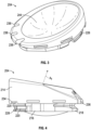
- Biomechanically derived loading for the humeral component can be estimated based on the muscle activation direction, here, the deltoid muscle, with lack of rotator cuff muscle contribution. This estimation can be fully understood by reference to A.Terrier et al., Simulated joint and muscle forces in reversed and anatomic shoulder prostheses. Journal of Bone & Joint Surgery, British Volume, 90(6) 751-756 (08). As shown in Figure 1 , the primary joint reaction force 102 is in the direction of the humeral axis, combining a compressive load vector 103 and a medial shear load vector 108 on the humeral articular surface.
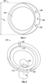
- a prosthesis system 200 for a joint comprises a tray 202 and a liner 204.
- the tray 202 has a lateral groove 206 disposed in an inner surface of a lateral circumferential portion 210 of a circumferential lip of the tray 202.
- the tray 202 also has a medial groove 208 disposed in an inner surface of a medial circumferential portion 212 of the circumferential lip of the tray 202.
- the lateral groove 206 and the medial groove 208 can comprise different portions of a single groove extending the circumference of the inner surface of the tray 202.
- the liner 204 can have an upper segment 214 and a lower segment 216.
- At least the lower segment 216 comprises a locking portion for lockingly engaging the tray 202.
- the locking portion is asymmetrical and comprises a lateral toe 218 positioned generally diametrically opposite a plurality of resiliently deformable medial fingers 220 defined therein.
- the liner 204 and the tray 202 are engageable in a lateral-to-medial direction so that the plurality of medial fingers 220 can resiliently deform to engage the medial groove 208 subsequent to engagement of the lateral toe 218 within the lateral groove 206.
- the plurality of medial fingers 220 can comprise from about 2 to about 6 medial fingers.
- the lateral toe 218 of the liner 204 can remain substantially undeformed during and subsequent to engagement within the lateral groove 206.
- the tray 202 and the liner 204 can be selectively rotationally oriented with respect to each other such that the lateral toe 218 of the liner 204 can be engaged within a middle portion of the lateral groove 206 of the tray 202 to resist disassociation of the liner 204 from the tray 202 when the prosthesis is subjected to physiological loading conditions.
- the lateral groove 206 of the tray 202 can further comprise a lateral locking lip 222 projecting radially inward from the inner surface of the lateral circumferential portion 210.
- the lateral toe 218 and the lateral locking lip 222 can cooperate to at least partially secure the liner 204 within the tray 202.
- the lateral toe 218 and the lateral locking lip 222 can cooperate to serve as the primary locking feature of the locking mechanism.
- the superior surface of the medial groove 208 of the tray 202 is formed by a medial locking lip 224 projecting radially inward from the inner surface of the medial circumferential portion 212 of the tray 202.
- a medial lead-in ramp 226 can extend from a point above the top surface of the medial locking lip 224 to the top surface of the medial locking lip 224.
- the medial lead-in ramp 226 provides a surface to guide the one or more resiliently deformable medial fingers 220 over the medial locking lip 224.
- the plurality of medial fingers 220 can further comprise a snap lip 228 projecting outward from the distal end of each of the plurality of medial fingers 220.
- the medial fingers 220 can resiliently deform when passing over the medial lead-in ramp 226 and return to a neutral position, for example, once the snap lips 228 pass the medial locking lip 224.
- the locking lip of the medial groove 208 and the snap lip 228 of each of the plurality of medial fingers 220 cooperate to at least partially secure the liner 204 within the tray 202.
- the plurality of medial fingers 220 and the snap lip 228 can serve as a secondary locking feature of the locking mechanism.
- the medial circumferential portion 212 of the tray 202 can further comprise a medial tab 230 that can extend from an upper surface thereof.
- a lower surface of the upper segment 214 of the liner 204 can define a medial female receptacle 234 for matingly receiving the medial tab 230 of the tray 202 in order to prevent rotation of the liner 204 relative to the tray 202 when engaged.
- the lower surface of the upper segment 214 of the liner 204 can further define a plurality of medial female receptacles 234 for receiving the medial tab 230.
- the liner 204 can have at least three medial female receptacles 234.
- Each of the plurality of female receptacles can correspond to a unique angular rotational position between the liner 204 and the tray 202.
- Each of the plurality of medial female receptacles 234 can have a center-to-center angular rotational measurement of from about 10 degrees to about 60 degrees. In one example, each of the plurality of medial female receptacles 234 can have a center-to-center angular rotational measurement of about 30 degrees. Adjusting the angular rotational position between the liner 204 and the tray 202 can provide for either or both of customizable balancing and customized constraint of the joint that can, for example, enable a surgeon to maximize joint stability.
- the lateral circumferential portion 210 of the tray 202 can further comprise a lateral tab 232 that can extend from an upper surface thereof. At least a portion of the upper segment 214 of the liner 204 proximate the lateral toe 218 can define a lateral female receptacle 236 for matingly receiving the lateral tab 232 of the tray 202 in order to prevent rotation of the liner 204 relative to the tray 202 when engaged.
- At least a portion of the upper segment 214 of the liner 204 proximate the lateral toe 218 can further define a plurality of lateral female receptacles 236, wherein each of the plurality of female receptacles corresponds to a unique angular rotational position between the liner 204 and the tray 202.
- the liner 204 can have at least three lateral female receptacles 236.
- Each of the plurality of lateral female receptacles 236 can have a center-to-center angular rotational measurement of from about 10 degrees to about 60 degrees. In one example, each of the plurality of lateral female receptacles 236 can have a center-to-center angular rotational measurement of about 30 degrees.
- the tray 202 can have an outside diameter of from about 30mm to about 50mm. In one example, the tray 202 can have an outside diameter of about 40 mm.
- the tray 202 can have a central through-hole 242 disposed therein.
- the center through-hole 242 can facilitate, for example, conversion assembly and tray removal.
- a tool can be inserted or threaded into the through-hole to lift the tray out of the stem.
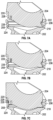
- an upper segment 214 of the liner 204 can define a face 244 that comprises an articulating surface.
- the face 244 can have a diameter D a of from about 30mm to about 50mm. In one example, the face 244 can have a diameter of from about 35mm to about 50mm. Some exemplary face diameters can include 36mm, 40mm, and 42mm.
- the face can have a face angle 246 measured between a stem axis A s and an axis A f normal to the face of less than about 150 degrees. In another aspect, the face can have a face angle 246 of from about 135 degrees to about 155 degrees.
- the liner 204 can comprise polyethylene.
- the polyethylene can comprise ultra high molecular weight polyethylene.
- the liner 204 can further comprise vitamin E.
- the liner 204 can be monolithic such that the upper segment 214 and the lower segment 216 are continuous or the upper segment 214 and the lower segment 216 can be joined to form the liner 204.
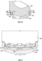
- Figures 7A-7D illustrate an exemplary method of assembling the liner 204 into the tray 202.
- a tray 202 and a liner 204 can be selectively rotationally oriented with respect to each other such that a lateral toe 218 of a lower segment 216 of a liner 204 can be aligned with a middle portion of a lateral groove 206 disposed in an inner surface of a lateral circumferential portion 210 of the tray 202.
- the lateral toe 218 of the liner 204 can be engaged in the lateral groove 206 of the tray 202 while the lateral tab 232 of the tray 202 can be disposed in a selected one of the plurality of lateral female receptacles 236 of the liner 204.
- a plurality of resiliently deformable medial fingers 220 can be deformed as they are urged into contact with the medial lead-in ramp 226 while the medial tab 232 can be disposed in a selected one of the plurality of medial female receptacles 234.
- the medial fingers 220 can return to a neutral position, for example, once the snap lips 228 pass the medial locking lip 224.
- the medial fingers 220 are disposed generally diametrically opposite the lateral toe 218 and the lateral toe 218 resists disassociation of the liner 204 from the tray 202 when the prosthesis is subjected to physiological loading conditions.
- inventive subject matter has been described with reference to specific example embodiments, various modifications and changes may be made to these embodiments without departing from the broader scope of embodiments of the present disclosure.
- inventive subject matter may be referred to herein, individually or collectively, by the term "invention" merely for convenience and without intending to voluntarily limit the scope of this application to any single disclosure or inventive concept if more than one is, in fact, disclosed.
- the term "or" may be construed in either an inclusive or exclusive sense. Moreover, plural instances may be provided for resources, operations, or structures described herein as a single instance. Additionally, boundaries between various resources, operations, modules, engines, and data stores are somewhat arbitrary, and particular operations are illustrated in a context of specific illustrative configurations. Other allocations of functionality are envisioned and may fall within a scope of various embodiments of the present disclosure. In general, structures and functionality presented as separate resources in the example configurations may be implemented as a combined structure or resource. Similarly, structures and functionality presented as a single resource may be implemented as separate resources. These and other variations, modifications, additions, and improvements fall within a scope of embodiments of the present disclosure where the invention is defined by the appended claims. The specification and drawings are, accordingly, to be regarded in an illustrative rather than a restrictive sense.
Claims (15)
- Système de prothèse (200), comprenant :un plateau (202) présentant une lèvre circonférentielle formant un évidement, la lèvre circonférentielle comportant une rainure latérale (206) disposée dans une surface interne d'une partie circonférentielle latérale (210) de la lèvre circonférentielle et une rainure médiale (208) disposée dans une surface interne d'une partie circonférentielle médiale (212) de la lèvre circonférentielle ; etun revêtement (204) pouvant être accouplé au plateau, avec une partie de verrouillage asymétrique (216), la partie de verrouillage asymétrique comprenant un orteil latéral (218) configuré pour venir en prise avec la rainure latérale dans le plateau et une pluralité de doigts médiaux (220) déformables élastiquement pour venir en prise avec la rainure médiale du plateau pour verrouiller le revêtement sur le plateau,dans lequel le revêtement et le plateau peuvent être mis en prise dans une direction latérale-médiale de sorte que la pluralité de doigts médiaux se déforment élastiquement pour venir en prise avec la rainure médiale après la mise en prise de l'orteil latéral dans la rainure latérale.
- Système (200) selon la revendication 1, dans lequel la partie circonférentielle médiale (212) du plateau (202) comporte en outre une patte médiale (230) s'étendant à partir d'une surface supérieure de celle-ci, et dans lequel le revêtement définit un réceptacle femelle médial (234) destiné à recevoir par accouplement la patte médiale du plateau.
- Système (200) selon la revendication 2, dans lequel le revêtement (204) définit une pluralité de réceptacles femelles médiaux (234) pour recevoir la patte médiale (230).
- Système (200) selon la revendication 3, dans lequel chacun de la pluralité de réceptacles femelles médiaux (234) correspond à une position de rotation angulaire unique entre le revêtement (204) et le plateau (202).
- Système (200) selon l'une quelconque des revendications 3 et 4, dans lequel chacun de la pluralité de réceptacles femelles médiaux (234) a une mesure de rotation angulaire centre à centre d'environ 10 à environ 60 degrés par rapport à des réceptacles femelles adjacents.
- Système (200) selon l'une quelconque des revendications 1 à 5, dans lequel la partie circonférentielle latérale (210) du plateau (202) comprend en outre une patte latérale (232) s'étendant à partir d'une surface supérieure de celle-ci, et dans lequel le revêtement à proximité de l'orteil latéral (218) définit un réceptacle femelle latéral (236) pour recevoir par accouplement la patte latérale du plateau.
- Système (200) selon la revendication 6, dans lequel le revêtement à proximité de l'orteil latéral (218) définit une pluralité de réceptacles femelles latéraux (236), dans lequel chacun de la pluralité de réceptacles femelles correspond à une position de rotation angulaire unique entre le revêtement (204) et le plateau (202).
- Système (200) selon l'une quelconque des revendications 1 à 7, dans lequel la surface supérieure de la rainure médiale (208) est formée par une lèvre de verrouillage médiale (224) faisant saillie radialement vers l'intérieur depuis la surface interne de la partie circonférentielle médiale (212) du plateau (202).
- Système (200) selon la revendication 8, comprenant en outre une rampe médiale de guidage (226) s'étendant d'un point situé au-dessus d'une surface supérieure de la lèvre de verrouillage médiale (224) jusqu'à la surface supérieure de la lèvre de verrouillage médiale.
- Système (200) selon l'une quelconque des revendications 1 à 9, dans lequel le plateau (202) comporte un trou traversant central (242).
- Système (200) selon l'une quelconque des revendications 1 à 10, dans lequel chacun de la pluralité de doigts médiaux (220) comprend en outre une lèvre d'encliquetage (228) faisant saillie radialement vers l'extérieur depuis une extrémité distale de celui-ci.
- Système (200) selon l'une quelconque des revendications 1 à 11, dans lequel le segment supérieur du revêtement (204) définit une face (244) comprenant une surface d'articulation.
- Système (200) selon la revendication 12, dans lequel la surface d'articulation a un diamètre d'environ 35 mm à environ 55 mm.
- Système (200) selon l'une quelconque des revendications 1 à 13, dans lequel la face (244) présente un angle de face inférieur à environ 150 degrés tel que mesuré entre un axe de tige et un axe normal à la face.
- Système (200) selon l'une quelconque des revendications 1 à 13, dans lequel la face (244) présente un angle de face de 135 degrés à 155 degrés.
Applications Claiming Priority (2)
| Application Number | Priority Date | Filing Date | Title |
|---|---|---|---|
| US201562210600P | 2015-08-27 | 2015-08-27 | |
| PCT/US2016/049015 WO2017035479A1 (fr) | 2015-08-27 | 2016-08-26 | Systèmes et prothèses d'épaule inversée à verrouillage directionnel |
Publications (2)
| Publication Number | Publication Date |
|---|---|
| EP3340937A1 EP3340937A1 (fr) | 2018-07-04 |
| EP3340937B1 true EP3340937B1 (fr) | 2024-03-20 |
Family
ID=56853899
Family Applications (1)
| Application Number | Title | Priority Date | Filing Date |
|---|---|---|---|
| EP16760332.3A Active EP3340937B1 (fr) | 2015-08-27 | 2016-08-26 | Systèmes et prothèses d'épaule inversée à verrouillage directionnel |
Country Status (7)
| Country | Link |
|---|---|
| US (2) | US10709565B2 (fr) |
| EP (1) | EP3340937B1 (fr) |
| JP (1) | JP6839176B2 (fr) |
| CN (2) | CN108024858A (fr) |
| AU (1) | AU2016310347B2 (fr) |
| CA (1) | CA2996707A1 (fr) |
| WO (1) | WO2017035479A1 (fr) |
Families Citing this family (29)
| Publication number | Priority date | Publication date | Assignee | Title |
|---|---|---|---|---|
| US20230080207A1 (en) | 2005-02-25 | 2023-03-16 | Shoulder Innovations, Inc. | Methods and devices for less invasive glenoid replacement |
| WO2007109340A2 (fr) | 2006-03-21 | 2007-09-27 | Axiom Orthopaedics, Inc. | Géométrie des tiges fémorale et humérale et techniques d'implantation pour reconstruction orthopédique d'articulation |
| US9662126B2 (en) | 2009-04-17 | 2017-05-30 | Arthrosurface Incorporated | Glenoid resurfacing system and method |
| EP2604226A1 (fr) | 2011-10-31 | 2013-06-19 | Tornier Orthopedics Ireland Ltd. | Prothèse d'épaule réversible modulaire |
| US10034759B2 (en) | 2012-10-29 | 2018-07-31 | Tornier Orthopedics Ireland Ltd. | Reverse shoulder implants |
| KR20150104117A (ko) | 2012-12-18 | 2015-09-14 | 이칸 스쿨 오브 메디슨 엣 마운트 시나이 | 인플루엔자 바이러스 백신 및 그의 용도 |
| WO2014159960A1 (fr) | 2013-03-14 | 2014-10-02 | Icahn School Of Medicine At Mount Sinai | Anticorps contre l'hémagglutinine du virus de la grippe et utilisations correspondantes |
| AU2016209032A1 (en) | 2015-01-23 | 2017-08-10 | Icahn School Of Medicine At Mount Sinai | Influenza virus vaccination regimens |
| AU2016246513B2 (en) * | 2015-04-07 | 2019-08-29 | Zimmer, Inc. | Convertible glenoid |
| JP6839176B2 (ja) | 2015-08-27 | 2021-03-03 | ジンマー,インコーポレイティド | 指向性係止用逆肩プロテーゼ及びシステム |
| US10588752B2 (en) * | 2016-03-29 | 2020-03-17 | Biomet Manufacturing, Llc | Modular bone model |
| CA3059036A1 (fr) | 2016-04-19 | 2017-10-26 | Imascap Sas | Implant humeral planifie avant operation et procede de planification |
| JP7237344B2 (ja) | 2016-06-15 | 2023-03-13 | アイカーン スクール オブ メディシン アット マウント サイナイ | インフルエンザウイルス血球凝集素タンパク質及びその使用 |
| WO2018039493A1 (fr) | 2016-08-24 | 2018-03-01 | Greiwe Raymond Michael | Système d'implant de tête humérale |
| US11197764B2 (en) | 2017-03-31 | 2021-12-14 | Howmedica Osteonics Corp. | Modular humeral head |
| CA3058652A1 (fr) | 2017-04-07 | 2018-10-11 | Icahn School Of Medicine At Mount Sinai | Anticorps anti-neuraminidase du virus influenza de type b et leurs utilisations |
| WO2018191420A1 (fr) | 2017-04-14 | 2018-10-18 | Shoulder Innovations, Llc | Prothèse totale d'épaule comportant un implant glénoïdien intégré pouvant passer d'une configuration anatomique à une configuration inverse |
| US11974925B2 (en) | 2017-09-25 | 2024-05-07 | Howmedica Osteonics Corp. | Patient specific stemless prosthesis anchor components |
| CA3087066A1 (fr) * | 2017-12-29 | 2019-07-04 | Tornier, Inc. | Elements constitutifs d'implant humeral specifiques a un patient |
| AU2019234645A1 (en) * | 2018-03-12 | 2020-10-29 | Shoulder Innovations, Inc. | Convertible total shoulder prosthesis |
| EP3833277A1 (fr) | 2018-08-10 | 2021-06-16 | Tornier, Inc. | Guides et instruments d'amélioration de la précision de mise en place d'implant glénoïde |
| JP7171909B2 (ja) | 2018-10-02 | 2022-11-15 | ハウメディカ オステオニクス コーポレイション | 上腕骨頭システムおよびそれを含むキット |
| EP3937857A4 (fr) | 2019-03-11 | 2022-11-02 | Shoulder Innovations, Inc. | Systèmes inversés totaux de l'épaule et procédés associés |
| US11478358B2 (en) | 2019-03-12 | 2022-10-25 | Arthrosurface Incorporated | Humeral and glenoid articular surface implant systems and methods |
| USD977643S1 (en) | 2019-03-12 | 2023-02-07 | Shoulder Innovations, Inc. | Humeral stem implant |
| KR102650843B1 (ko) * | 2019-04-25 | 2024-03-22 | 앙코르 메디컬, 엘.피.(디/비/에이 디제이오 서지컬) | 관절와 임플란트 시스템 |
| USD938590S1 (en) | 2019-10-01 | 2021-12-14 | Howmedica Osteonics Corp. | Humeral implant |
| CN111374805B (zh) * | 2020-03-25 | 2022-05-17 | 北京市春立正达医疗器械股份有限公司 | 一种组配式肩关节假体及其制造方法 |
| WO2023183283A1 (fr) * | 2022-03-21 | 2023-09-28 | Shoulder Innovations, Inc. | Prothèse d'épaule humérale convertible sans tige |
Citations (2)
| Publication number | Priority date | Publication date | Assignee | Title |
|---|---|---|---|---|
| US20050143832A1 (en) * | 2003-10-17 | 2005-06-30 | Carson Christopher P. | High flexion articular insert |
| US20110098823A1 (en) * | 2009-08-26 | 2011-04-28 | Zimmer, Gmbh | Tibial component with flexible rim |
Family Cites Families (24)
| Publication number | Priority date | Publication date | Assignee | Title |
|---|---|---|---|---|
| US4784663A (en) | 1986-02-19 | 1988-11-15 | Pfizer Hospital Products Group, Inc. | Acetabular cup assembly |
| US4964865A (en) | 1988-02-03 | 1990-10-23 | Intermedics Orthopedics, Inc. | Glenoid prosthesis and method of use |
| US4938769A (en) * | 1989-05-31 | 1990-07-03 | Shaw James A | Modular tibial prosthesis |
| US5935175A (en) | 1998-03-13 | 1999-08-10 | Johnson & Johnson Professional, Inc. | Acetabular prosthesis with ring lock mechanism |
| JP2000013477A (ja) * | 1998-06-25 | 2000-01-14 | Kenwood Corp | 透明カバーの取り付け構造 |
| US6126692A (en) | 1998-06-25 | 2000-10-03 | New York Society For The Relief Of The Ruptured And Crippled Maintaining The Hospital For Special Surgery | Retaining mechanism for a modular tibial component of a knee prosthesis |
| FR2780635B1 (fr) * | 1998-07-06 | 2000-10-20 | Tornier Sa | Dispositif pour la fixation d'un insert en matiere plastique |
| US6500208B1 (en) | 1998-10-16 | 2002-12-31 | Biomet, Inc. | Nonmodular joint prosthesis convertible in vivo to a modular prosthesis |
| US6569202B2 (en) | 2001-04-02 | 2003-05-27 | Whiteside Biomechanics, Inc. | Tray and liner for joint replacement system |
| GB0201149D0 (en) | 2002-01-18 | 2002-03-06 | Finsbury Dev Ltd | Prosthesis |
| US6679916B1 (en) * | 2002-04-29 | 2004-01-20 | Mark A. Frankle | Shoulder prosthesis system |
| US8062376B2 (en) | 2002-07-10 | 2011-11-22 | Biomet Manufacturing Corp. | Shoulder implant assembly |
| CA2511216C (fr) | 2002-12-20 | 2011-02-01 | Smith & Nephew, Inc. | Protheses du genou a hautes performances |
| US6969407B2 (en) | 2003-12-22 | 2005-11-29 | Depuy Products, Inc. | Modular radial component for a total wrist arthroplasty |
| US20060069445A1 (en) | 2004-09-27 | 2006-03-30 | Ondrla Jeffrey M | Extended articulation prosthesis adaptor and associated method |
| WO2007031575A1 (fr) * | 2005-09-16 | 2007-03-22 | Zimmer Gmbh | Plateau et coquille d'un dispositif de reception d'une rotule |
| GB0519994D0 (en) | 2005-10-01 | 2005-11-09 | Depuy Ireland Ltd | Humeral component of a shoulder joint prosthesis |
| CA2631580C (fr) * | 2006-01-20 | 2015-01-13 | Zimmer Technology, Inc. | Systeme pour arthroplastie de l'epaule |
| FR2920963B1 (fr) * | 2007-09-19 | 2010-09-10 | Tornier Sa | Composant de prothese articulaire et prothese articulaire comprenant un tel composant |
| US9204967B2 (en) | 2007-09-28 | 2015-12-08 | Depuy (Ireland) | Fixed-bearing knee prosthesis having interchangeable components |
| FR2951633A1 (fr) | 2009-10-23 | 2011-04-29 | Wilko Fockens | Prothese d'epaule a tige universelle avec vis d'osteosynthese verrouillees |
| EP2604226A1 (fr) * | 2011-10-31 | 2013-06-19 | Tornier Orthopedics Ireland Ltd. | Prothèse d'épaule réversible modulaire |
| US10034759B2 (en) * | 2012-10-29 | 2018-07-31 | Tornier Orthopedics Ireland Ltd. | Reverse shoulder implants |
| JP6839176B2 (ja) | 2015-08-27 | 2021-03-03 | ジンマー,インコーポレイティド | 指向性係止用逆肩プロテーゼ及びシステム |
-
2016
- 2016-08-26 JP JP2018510740A patent/JP6839176B2/ja active Active
- 2016-08-26 CN CN201680052697.4A patent/CN108024858A/zh active Pending
- 2016-08-26 CA CA2996707A patent/CA2996707A1/fr active Pending
- 2016-08-26 US US15/248,868 patent/US10709565B2/en active Active
- 2016-08-26 CN CN202210624840.XA patent/CN114848240A/zh active Pending
- 2016-08-26 EP EP16760332.3A patent/EP3340937B1/fr active Active
- 2016-08-26 WO PCT/US2016/049015 patent/WO2017035479A1/fr active Application Filing
- 2016-08-26 AU AU2016310347A patent/AU2016310347B2/en active Active
-
2020
- 2020-06-03 US US16/891,990 patent/US11969353B2/en active Active
Patent Citations (2)
| Publication number | Priority date | Publication date | Assignee | Title |
|---|---|---|---|---|
| US20050143832A1 (en) * | 2003-10-17 | 2005-06-30 | Carson Christopher P. | High flexion articular insert |
| US20110098823A1 (en) * | 2009-08-26 | 2011-04-28 | Zimmer, Gmbh | Tibial component with flexible rim |
Also Published As
| Publication number | Publication date |
|---|---|
| US11969353B2 (en) | 2024-04-30 |
| AU2016310347A1 (en) | 2018-03-08 |
| US10709565B2 (en) | 2020-07-14 |
| CN108024858A (zh) | 2018-05-11 |
| WO2017035479A1 (fr) | 2017-03-02 |
| CN114848240A (zh) | 2022-08-05 |
| US20170056187A1 (en) | 2017-03-02 |
| EP3340937A1 (fr) | 2018-07-04 |
| AU2016310347B2 (en) | 2020-08-06 |
| CA2996707A1 (fr) | 2017-03-02 |
| JP2018525160A (ja) | 2018-09-06 |
| JP6839176B2 (ja) | 2021-03-03 |
| US20200289278A1 (en) | 2020-09-17 |
Similar Documents
| Publication | Publication Date | Title |
|---|---|---|
| US11969353B2 (en) | Directional locking reverse shoulder prostheses and systems | |
| AU2020233662B2 (en) | Improved glenoid anchor for a shoulder joint prosthesis | |
| US20130245775A1 (en) | Joint implant trial components | |
| US9084680B2 (en) | Multiple bearing humeral prosthesis | |
| US8308810B2 (en) | Multiple bearing acetabular prosthesis | |
| US20160270922A1 (en) | Glenoid Anchor for a Shoulder Joint Prosthesis | |
| CN104411272B (zh) | 假体踝关节部件 | |
| US9204978B2 (en) | Modular screw apparatus and method | |
| EP4335414A2 (fr) | Implant glénoïdien | |
| EP3741329A1 (fr) | Fixation de palier | |
| US20190021867A1 (en) | Shoulder Joint Prosthesis | |
| US10433968B2 (en) | Prosthesis for joint shoulder reconstruction | |
| CN103429194A (zh) | 关节窝特别是用于髋内假体的髋臼关节窝 | |
| US20110184521A1 (en) | Prosthesis connection mechanism | |
| KR20120126056A (ko) | 인공고관절용 비구컵 어셈블리 | |
| KR20120126055A (ko) | 인공고관절용 비구컵 및 폴리에틸렌 베어링 및 비구컵 어셈블리 |
Legal Events
| Date | Code | Title | Description |
|---|---|---|---|
| STAA | Information on the status of an ep patent application or granted ep patent |
Free format text: STATUS: UNKNOWN |
|
| STAA | Information on the status of an ep patent application or granted ep patent |
Free format text: STATUS: THE INTERNATIONAL PUBLICATION HAS BEEN MADE |
|
| PUAI | Public reference made under article 153(3) epc to a published international application that has entered the european phase |
Free format text: ORIGINAL CODE: 0009012 |
|
| STAA | Information on the status of an ep patent application or granted ep patent |
Free format text: STATUS: REQUEST FOR EXAMINATION WAS MADE |
|
| 17P | Request for examination filed |
Effective date: 20180326 |
|
| AK | Designated contracting states |
Kind code of ref document: A1 Designated state(s): AL AT BE BG CH CY CZ DE DK EE ES FI FR GB GR HR HU IE IS IT LI LT LU LV MC MK MT NL NO PL PT RO RS SE SI SK SM TR |
|
| AX | Request for extension of the european patent |
Extension state: BA ME |
|
| DAV | Request for validation of the european patent (deleted) | ||
| DAX | Request for extension of the european patent (deleted) | ||
| GRAP | Despatch of communication of intention to grant a patent |
Free format text: ORIGINAL CODE: EPIDOSNIGR1 |
|
| STAA | Information on the status of an ep patent application or granted ep patent |
Free format text: STATUS: GRANT OF PATENT IS INTENDED |
|
| INTG | Intention to grant announced |
Effective date: 20231005 |
|
| GRAS | Grant fee paid |
Free format text: ORIGINAL CODE: EPIDOSNIGR3 |
|
| GRAA | (expected) grant |
Free format text: ORIGINAL CODE: 0009210 |
|
| STAA | Information on the status of an ep patent application or granted ep patent |
Free format text: STATUS: THE PATENT HAS BEEN GRANTED |
|
| AK | Designated contracting states |
Kind code of ref document: B1 Designated state(s): AL AT BE BG CH CY CZ DE DK EE ES FI FR GB GR HR HU IE IS IT LI LT LU LV MC MK MT NL NO PL PT RO RS SE SI SK SM TR |
|
| REG | Reference to a national code |
Ref country code: GB Ref legal event code: FG4D |
|
| REG | Reference to a national code |
Ref country code: CH Ref legal event code: EP |
|
| REG | Reference to a national code |
Ref country code: DE Ref legal event code: R096 Ref document number: 602016086427 Country of ref document: DE |
|
| P01 | Opt-out of the competence of the unified patent court (upc) registered |
Effective date: 20240320 |