EP3958709B1 - Applikatorendstück zum auftragen eines kosmetischen produkts, dazugehöriger applikator und applikatoranordnung - Google Patents
Applikatorendstück zum auftragen eines kosmetischen produkts, dazugehöriger applikator und applikatoranordnung Download PDFInfo
- Publication number
- EP3958709B1 EP3958709B1 EP20830225.7A EP20830225A EP3958709B1 EP 3958709 B1 EP3958709 B1 EP 3958709B1 EP 20830225 A EP20830225 A EP 20830225A EP 3958709 B1 EP3958709 B1 EP 3958709B1
- Authority
- EP
- European Patent Office
- Prior art keywords
- applicator
- end piece
- central element
- cosmetic product
- applicator end
- Prior art date
- Legal status (The legal status is an assumption and is not a legal conclusion. Google has not performed a legal analysis and makes no representation as to the accuracy of the status listed.)
- Active
Links
Images







Classifications
-
- A—HUMAN NECESSITIES
- A45—HAND OR TRAVELLING ARTICLES
- A45D—HAIRDRESSING OR SHAVING EQUIPMENT; EQUIPMENT FOR COSMETICS OR COSMETIC TREATMENTS, e.g. FOR MANICURING OR PEDICURING
- A45D40/00—Casings or accessories specially adapted for storing or handling solid or pasty toiletry or cosmetic substances, e.g. shaving soaps or lipsticks
- A45D40/26—Appliances specially adapted for applying pasty paint, e.g. using roller, using a ball
-
- A—HUMAN NECESSITIES
- A45—HAND OR TRAVELLING ARTICLES
- A45D—HAIRDRESSING OR SHAVING EQUIPMENT; EQUIPMENT FOR COSMETICS OR COSMETIC TREATMENTS, e.g. FOR MANICURING OR PEDICURING
- A45D34/00—Containers or accessories specially adapted for handling liquid toiletry or cosmetic substances, e.g. perfumes
- A45D34/04—Appliances specially adapted for applying liquid, e.g. using roller or ball
- A45D34/042—Appliances specially adapted for applying liquid, e.g. using roller or ball using a brush or the like
- A45D34/045—Appliances specially adapted for applying liquid, e.g. using roller or ball using a brush or the like connected to the cap of the container
-
- A—HUMAN NECESSITIES
- A45—HAND OR TRAVELLING ARTICLES
- A45D—HAIRDRESSING OR SHAVING EQUIPMENT; EQUIPMENT FOR COSMETICS OR COSMETIC TREATMENTS, e.g. FOR MANICURING OR PEDICURING
- A45D34/00—Containers or accessories specially adapted for handling liquid toiletry or cosmetic substances, e.g. perfumes
- A45D34/04—Appliances specially adapted for applying liquid, e.g. using roller or ball
-
- A—HUMAN NECESSITIES
- A45—HAND OR TRAVELLING ARTICLES
- A45D—HAIRDRESSING OR SHAVING EQUIPMENT; EQUIPMENT FOR COSMETICS OR COSMETIC TREATMENTS, e.g. FOR MANICURING OR PEDICURING
- A45D40/00—Casings or accessories specially adapted for storing or handling solid or pasty toiletry or cosmetic substances, e.g. shaving soaps or lipsticks
- A45D40/26—Appliances specially adapted for applying pasty paint, e.g. using roller, using a ball
- A45D40/28—Appliances specially adapted for spreading already applied paint
-
- A—HUMAN NECESSITIES
- A45—HAND OR TRAVELLING ARTICLES
- A45D—HAIRDRESSING OR SHAVING EQUIPMENT; EQUIPMENT FOR COSMETICS OR COSMETIC TREATMENTS, e.g. FOR MANICURING OR PEDICURING
- A45D40/00—Casings or accessories specially adapted for storing or handling solid or pasty toiletry or cosmetic substances, e.g. shaving soaps or lipsticks
- A45D2040/0006—Accessories
-
- A—HUMAN NECESSITIES
- A45—HAND OR TRAVELLING ARTICLES
- A45D—HAIRDRESSING OR SHAVING EQUIPMENT; EQUIPMENT FOR COSMETICS OR COSMETIC TREATMENTS, e.g. FOR MANICURING OR PEDICURING
- A45D40/00—Casings or accessories specially adapted for storing or handling solid or pasty toiletry or cosmetic substances, e.g. shaving soaps or lipsticks
- A45D2040/0012—Casings or accessories specially adapted for storing or handling solid or pasty toiletry or cosmetic substances, e.g. shaving soaps or lipsticks with special decorative arrangements or form
-
- A—HUMAN NECESSITIES
- A45—HAND OR TRAVELLING ARTICLES
- A45D—HAIRDRESSING OR SHAVING EQUIPMENT; EQUIPMENT FOR COSMETICS OR COSMETIC TREATMENTS, e.g. FOR MANICURING OR PEDICURING
- A45D40/00—Casings or accessories specially adapted for storing or handling solid or pasty toiletry or cosmetic substances, e.g. shaving soaps or lipsticks
- A45D2040/0025—Details of lipstick or like casings
- A45D2040/0031—Replacement of the stick
Definitions
- the invention relates to an applicator tip for a cosmetic product, an applicator and an associated applicator assembly.
- the invention further relates to a method for manufacturing such an applicator tip.
- Applicator assemblies are known for cosmetic products, for example for cosmetic products intended to be applied to the lips of a user.
- Said applicator assemblies comprise a container containing the cosmetic product and an applicator adapted to be removably attached to the container.
- the container generally comprises a body, the body comprising walls defining a reservoir in which the cosmetic product is contained, and a neck defining an opening through which the cosmetic product can be extracted.
- the applicator generally includes a cap adapted to be attached to the neck, a stem extending from the cap and an applicator tip attached to a free end of the stem. When the cap is attached to the neck, the stem and applicator tip extend inside the reservoir. The applicator is immersed in the cosmetic product contained in the reservoir. To use the applicator, the user detaches the cap from the neck and extracts the applicator from the container.
- Known applicator tips generally have a spatula-shaped area intended to come into contact with the part to be made up, in particular to load them with cosmetic product.
- the spatula-shaped area does not allow usually only a local application of cosmetic product, for example on one lip at a time.
- the spatula also presents an uncomfortable rigidity when pressure is exerted on the part to be made up.
- WO 2016/042216 describes an applicator tip with a central element.
- the present invention aims to provide an applicator tip making it possible to apply makeup, in a single application, to an extended area of a user, for example both lips, while maintaining comfort of use during makeup.
- envelope we mean to completely surround. In other words, the central element is surrounded by free space.
- the free space in the central cavity makes it possible to form a cosmetic product reservoir volume. It is thus possible to apply the cosmetic product to a large surface, such as the lips in a single application.
- the free space makes it possible to provide suppleness and flexibility to the external envelope which is however limited by the presence of the central element so as to provide comfort of use during makeup.
- the invention also relates to the applicator assembly, the container of which is filled with cosmetic product.
- the cosmetic product is viscous, pasty or liquid.
- the product is preferably intended for makeup of a user's lips.
- the invention finally relates to a method for manufacturing an applicator tip for a cosmetic product as described above.
- the invention relates to an applicator tip 1 extending along a direction of longitudinal extension, called the main direction X, from a proximal end 1a towards a distal end 1b.
- the internal surface 3i of the external envelope 3 is at a distance do, dl from the central element 7 in a direction orthogonal to the direction of longitudinal extension and in the longitudinal direction so as to define a free space surrounding the central element 7.
- the applicator tip 1 comprises a sleeve 9.
- the sleeve 9 is intended to be assembled with a rod 11, here embedded in the rod 11, to form an applicator.
- the sleeve 9 extends from the proximal end 1a of the application part 20 along said main direction X in the direction opposite to that which points towards the distal end 1b of the applicator tip 1.
- the central element 7 is entirely placed inside the cavity 5.
- the central element 7 is circumscribed inside the cavity 5.
- the central element 7 can be in material connection with the outer envelope 3.
- the central element 7 is in material connection at the distal end 1b or at the proximal end 1a.
- the central element 7 can also be in material connection with the rest of the external envelope 3, for example by material bridges, so that this connection does not prevent movement of the external envelope 3 in direction of the central element 7 or opposite to the central element 7.
- the central element 7 can be without any connection with the external envelope 3.
- the outer envelope 3 is designed so as to maintain the central element 7 inside the cavity 5.
- the outer envelope 3 is formed of a small thickness of material, preferably between 0.3 and 1.5 mm.
- the external surface 3e and the internal surface 3i of the external envelope 3 are spaced from 0.3 to 1.5 mm.
- This low thickness provides flexibility and suppleness to the outer envelope 3 which can be easily moved and crushed thanks to the free space enveloping the central element 7 as described below.
- the movement of the outer envelope 3 can be observed in particular when a pressure P is exerted on it, for example during the passage of the tip applicator 1 in an opening (neck 29, wiper 31) of a container 33 or during its application to a surface to be made up.
- the outer envelope 3 comprises at least one orifice 19, 25, 27 so as to allow entry and/or exit of the cosmetic product through it.
- These entry and/or exit of cosmetic product are advantageously favored by the movement of the outer envelope 3 as explained below.
- the outer envelope 3 is compressed towards the central element 7 causing a pressure P on the cosmetic product contained in the cavity 5, causing its exit. This pressure P also makes it possible to improve the distribution of the cosmetic product in cavity 5.
- the orifices 19, 25, 27 are dimensioned so that the central element 7 cannot exit the cavity 5.
- the cavity 5 thus serves as a reservoir of cosmetic product which is returned to the applicator part via at least one orifice 19, 25, 27.
- the outer envelope 3 has an oblong shape, elongated in the main direction X.
- the outer envelope 3 has a cross section of variable diameter whose maximum diameter d3 is located near the proximal end 1a. This shape at the proximal end 1a provides a large application surface.
- the outer envelope 3 has a refined distal end 1b, in particular conical.
- This refined shape at the distal end 1b makes it possible to provide a precision application surface and facilitates the introduction of the applicator tip 1 into a container 33 containing the cosmetic product.
- the central element 7 can have a variable general shape.
- the central element 7 may have a shape similar to the shape of the outer envelope 3, such as an oblong shape or even be of spherical shape.
- the application part can comprise several different application zones 13, 15.
- the application part comprises a first application zone 13 extending in the main direction X from the proximal end 1a of the applicator tip 1 towards an intermediate position 1c and a second application zone 15 s extending in the main direction X from the intermediate position 1c towards the distal end 1b of the applicator tip 1.
- Each of the application zones 13, 15 may or may not include orifices 19, 25, 27, in particular orifices 19, 25, 27 of different dimensions. This makes it possible to have an applicator tip 1 with application zones 13, 15 of a different nature and can thus offer a diversity of makeup effects.
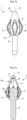
- THE figures 1 to 4 illustrate a first embodiment of an applicator tip 1 for a cosmetic product according to the invention.
- the applicator tip 1, in particular the outer casing 3 has the general shape of a flame whose cross section to the main direction X fits into a circle of variable diameter along the main direction X and whose maximum diameter is d3.
- the first application zone 13 is of generally spherical shape (denoted S in the figure).
- the radius of curvature is preferably between 2 and 8 mm.
- the second application zone 15 is of generally conical shape (denoted C on the figure 1 ), notably conical with a rounded top.
- the applicator tip 1 has a lower portion near the sleeve 9 convex outwards and an opposite upper portion of slightly concave shape towards the outside, the junction between the two portions being made at the level of the maximum diameter d3.
- This shape is also particularly suited to the shape of the lips and the applicator tip 1 thus has a large application surface.
- this shape allows simultaneous application to the upper lip and the lower lip.
- the pointed distal end 1b allows more careful and more precise application of the cosmetic product on a less accessible surface, for example the corner of the lips or even the contour of the lips.
- the spherical part provides a large application surface.
- the outer envelope 3, the cavity 5 and the central element 7 are of similar shape. They each have a maximum diameter d3, d5, d7 at the level of the maximum diameter d3 of the external envelope 3.
- the central element 7 is in material connection with the outer casing 3 at the level of the proximal end 1a of the applicator tip 1 by a connecting part 17.
- the central element 7 is in the extension of the sleeve 9 and extends towards the distal end 1b of the applicator tip 1.
- This connecting part 17 provides rigidity to the central element 7 which is thus fixed relative to the sleeve 9.
- the first zone d the application 13 comprises a plurality of longitudinal slots 19 extending from the proximal end 1a of the applicator tip 1 towards the intermediate position 1c parallel to the main direction X.
- the slots 19 are of oblong shape and have a maximum transverse width at the level of the maximum diameter d3 of the external envelope 3.
- the slots 19 are separated by strips 21 of material which extend from the proximal end 1a of the applicator tip 1 towards the intermediate position 1c parallel to the main direction X. These strips 21 are of constant width and form the outer envelope 3.
- This first embodiment comprises six longitudinal slots 19 spaced apart from six strips 21 of material.
- the second application zone 15 has no orifice.
- the slots 19 allow the restitution of the cosmetic product at the level of the first application zone 13.
- the slots 19 extend to the second application zone 15 and are sufficiently elongated to allow distribution of the product cosmetic at the level of the second application zone 15.
- THE figures 5 and 6 illustrate a second embodiment of an applicator tip 1 for a cosmetic product according to the invention.
- This second embodiment differs from the first embodiment by the shape of the central element 7.
- the central element 7 is a sphere connected to the outer envelope 3 at the level of the proximal end 1a of the tip.
- the central element 7 is thus located in the cavity 5 defined at the level of the first application zone 13 releasing a significant free space at the level of the second application zone 15.
- the central element 7 has a diameter designed so that there is a free space between the central element 7 and the internal surface 3i of the external envelope 3.
- the radius of curvature of the central element 7 is between 1 and 6 mm.
- THE figures 7 and 8 illustrate a third embodiment of an applicator tip 1 for a cosmetic product according to the invention.
- This third embodiment differs from the first embodiment by the orientation of the longitudinal slots 19 at the level of the first application zone 13.
- the slots 19 here present a helical winding around the main direction to have orifices all around the applicator tip 1 and thus a restitution of the product stored in the cavity 5 over the entire application surface.
- the strips 21 of material between the slots 19 also have a width less than the width of the strips 21 of material of the first and second embodiments.
- the outer envelope 3 is thus more flexible and has greater flexibility when a pressure P is exerted, favoring the exit of the cosmetic product through the slots 19.
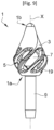
- THE figures 9 And 10 illustrate a fourth embodiment of an applicator tip 1 for a cosmetic product according to the invention.
- This fourth embodiment differs from the third embodiment by the shape of the central element 7.
- the central element 7 is here a sphere connected to the outer envelope 3 at the level of the proximal end 1a of the tip.
- the central element 7 is thus located in the cavity 5 defined at the level of the first application zone 13.
- the connection with the external envelope 3 is made via a narrow connecting part 17, in particular narrower that in the second embodiment illustrated in figures 5 and 6 .
- the cavity 5 thus has a larger volume, which increases the cosmetic product storage capacity of the applicator tip 1.
- the reduction in the cross section of the connecting part 17 makes it possible to provide flexibility to the central element 7 and thus flexibility to the applicator tip.
- THE figures 11 And 12 illustrate a fifth embodiment of an applicator tip 1 for a cosmetic product according to the invention. This fifth embodiment differs from the fourth embodiment by the connection of the central element 7 with the outer envelope 3.
- the central element 7 is a sphere but it is connected to the outer envelope 3 at the distal end 1b.
- the central element 7 is an extension of the distal end 1b and extends into the cavity 5 towards the sleeve 9.
- the tip does not have a cavity 5 at the level of the second application zone 15, In other words, the interior of this second application zone 15 is full. Cavity 5 is only located at the level of the first application zone 13.
- the slots 19 wind helically around the main direction X. They extend from the proximal end 1a to the second application zone 15.
- the slots 19 open into the cavity 5 located at the level of the first application zone 13 and form channels 23 at the level of the second application zone 15.
- Cosmetic product is thus available at the two application zones 13, 15.
- THE figures 13 to 16 illustrate a sixth embodiment of an applicator tip 1 for a cosmetic product according to the invention. This sixth embodiment differs from the first embodiment by the presence of a plurality of orifices at the level of the second application zone 15.
- the orifices of the second application zone 15 are circular orifices 25 with a diameter preferably between 0.5 and 3 mm.
- the circular orifices 25 are arranged in two radial rows. Each of the rows comprises six circular orifices 25. For better restitution over the entire surface of the second application zone 15, the circular orifices 25 of a radial row have an angular offset relative to the circular orifices 25 of the other radial row.
- the slots 19 are also shorter than in the first embodiment and extend over only the first application zone 13.
- cosmetic product can be returned to the two application zones 13, 15.
- the circular orifices 25 of the second application zone 15 are thus smaller in size than the orifices (slots 19) of the first application zone 13.
- the quantity of product returned varied. It is thus possible to restore a small quantity of product by applying a pressure P at the second application zone 15 and a larger quantity by applying a pressure P at the first application zone 13.
- THE figures 17 And 18 illustrate a seventh embodiment of an applicator tip 1 for a cosmetic product according to the invention.
- This seventh embodiment differs from the sixth embodiment by the orientation of the longitudinal slots 19 at the level of the first application zone 13.
- the slots 19 have a helical winding around the main direction X.
- THE figures 19 And 20 illustrate an eighth embodiment of an applicator tip 1 for a cosmetic product according to the invention.
- This eighth embodiment differs from the seventh embodiment by the shape of the orifices of the second application zone 15 which are in the form of secondary slots 27, here six in number, which are of smaller dimension than that of the slots 19 of the first application zone 13 so as to be able to regulate the quantity of cosmetic product returned.
- the secondary slots 27 extend longitudinally over almost the entire length of the second application zone 15 and have an inclination relative to the main direction surface of the second application zone 15.
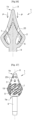
- the first mechanism of use is illustrated in figures 1 to 4 taking as an example the applicator tip 1 of the first embodiment. This mechanism is however applicable to any applicator tip 1 according to the invention.
- THE figures 1 And 2 illustrate the applicator tip 1 in a position in which no pressure is exerted on the external surface 3e of the external envelope 3.
- a free space is defined all around the central element 7 and envelops it, apart from at the level of the connecting part 17 between the outer envelope 3 and the central element 7.
- the flexibility of the external envelope 3 causes its movement.
- the outer envelope 3 approaches the central element 7 which remains fixed in relation to the sleeve 9 as is visible in the Figure 3 .
- the zone of the outer envelope 3 opposite the pressure point moves away from the central element 7.
- This movement causes the cosmetic product stored in the cavity 5 to exit through the orifices (here slots 19) located at the level of the first application zone 13.
- the slots 19 are sufficiently elongated towards the distal end 1b of the tip so that the second application zone 15 is also supplied with cosmetic product.
- a more sustained pressure P causes the movement of the outer envelope 3 until the internal surface 3i of this is in contact with the central element 7 as is visible in the Figure 4 .
- the pressure P applied to the applicator tip 1 is applied radially.
- an axial pressure P that is to say a pressure P at the distal end 1b of the tip.
- the second mechanism of use is illustrated in figures 13 to 16 taking as an example the applicator tip 1 of the sixth embodiment. This mechanism is however applicable to any applicator tip 1 according to the invention.
- THE figures 13 And 14 illustrate the applicator tip 1 in a position in which no pressure is exerted on the external surface 3e of the external envelope 3.
- a free space is defined all around the central element 7 and surrounds it, apart from at the level of the connecting part 17 between the outer envelope 3 and the central element 7.
- a pressure P exerted at the distal end 1b of the applicator tip 1 causes a movement of the outer envelope 3. This movement is allowed by the flexibility of the external envelope 3.
- the free space between the internal surface 3i of the external envelope 3 and the central element 7 is reduced when the pressure P is applied.
- the distance dl, do between the internal surface 3i of the external envelope 3 and the central element 7 decreases all around the tip, in particular at the level of the second application zone 15.
- This pressure P is particularly advantageous for letting out cosmetic product through the orifices 25, 27 at the level of the second application zone 15.
- the two operating mechanisms can be combined.
- the applicator tip 1 is a single monolithic part obtained without assembly. In other words, the applicator tip 1 is not obtained by assembly.
- Assembly is understood here as the act of putting together or bringing together at least two isolated elements, but does not exclude the possibility of several stages.
- the applicator tip 1 described above is obtained by an additive manufacturing process.
- additive manufacturing process we mean a manufacturing process by adding material, generally computer-assisted. Such a manufacturing process is also called three-dimensional printing or 3D printing.
- the use of three-dimensional printing can make it possible to produce in a single step an applicator tip 1 in a single piece and in continuity of material comprising an external envelope 3 and a central element 7.
- Such an applicator tip 1 could prove to be very complex or even impossible to obtain, particularly in a single piece, by a conventional injection molding process. It is thus possible to produce, directly and by a single manufacturing operation, the applicator tip 1.
- this technique makes it possible to avoid the use of complex molds.
- these are sintering and/or stereolithography technologies.
- the digital model is a computer file which corresponds to a virtual model of the applicator tip 1.
- the applicator tip 1 is first modeled so as to obtain a CAD model which is then converted into a format appropriate such as an .STL file.
- the file is then used on an additive manufacturing machine.
- the digital model is divided into a certain number of layers depending on the desired precision.
- the layers correspond to a cross section of the tip applicator 1, that is to say a section of the applicator tip 1 taken in a plane perpendicular to the main direction X.
- the materials suitable for manufacturing the applicator tip 1 by three-dimensional printing are polyamides, photosensitive resins , polylactic acid (PLA), acrylonitrile butadiene styrene (ABS), polypropylene (PP).
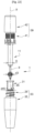
- THE figures 21 And 22 illustrate an applicator assembly for a cosmetic product, comprising a container 33 comprising a body 35 forming a reservoir intended to contain the cosmetic product, and an applicator comprising an applicator tip 1 such as that of the seventh embodiment described above.
- the applicator is adapted to be fixed on the container 33, so that the applicator tip 1 is housed inside the reservoir. He is thus immersed in the cosmetic product marked 37 on the Figure 21 .
- FIG. 21 also illustrates the sleeve 9 assembled with the rod 11 of the applicator, called the handling rod 11.
- the rod 11 allows, among other things, manipulation of said applicator tip 1. More precisely, the applicator comprises a closing cap 39 adapted to be manipulated by the user and the rod 11 advantageously extends from the cap 39.
- the plug 39 is formed of a head 41 made from the material with the rod 11, and of a cover 43 force-fitted and held in position on the head 41 of rod 11 using internal counter-forms intended to cooperate with shapes made on the head 41.
- the cover 43 is rigid. By “rigid” we mean that it is not deformable either under atmospheric pressure or under pressure exerted by the fingers of a user. It is with the help of said cover 43 that the user manipulates the applicator of the invention, in particular because the cover 43 imparts the movement that the user gives it to the head 41 of the rod 11, which itself transmits this movement to the sleeve 9 with which it is assembled.
- the cap 39 is intended to be removably fixed to an opening belonging to the container 33. Said opening is here the neck 29 through which the cosmetic product can be extracted.
- the sleeve 9 and the rod 11 each have a substantially cylindrical shape and a main direction of longitudinal extension coincident with the main direction X.
- FIG. 22 is an exploded view of the applicator assembly of the Figure 21 .
- the container 33 comprises the wringer 31, intended to be fixed inside said neck 29.
- the wiper 31 comprises a wiper orifice 45 configured to scrape the excess cosmetic product off the rod 11 and onto the applicator tip 1 when the latter pass through it.
- the spin orifice 45 is advantageously cylindrical in shape; this choice is not limiting and any other shape of orifice 45 could be chosen for the wringer 31 without departing from the scope of the invention.
- the diameter d45 of said wringing orifice will advantageously be chosen in relation to the diameter D of the rod 11 and the maximum diameter d3 of the applicator tip 1 from which it scrapes the excess product on board.
- the diameter d45 of the wiping orifice 45 can be substantially the same as the diameter d3 of the applicator tip 1. This has the advantage of hardly scraping the product off the applicator tip 1.
- the outer envelope 3 being soft and flexible, it is possible that the diameter d45 of the wiping orifice 45 is slightly less than the diameter d3 of the applicator tip 1. This has the advantage of distributing the cosmetic product stored in the cavity and to eliminate any excess stored in the cavity 5.
- the applicator assembly is designed in such a way that the wringing of the applicator tip 1 is optimized during its extraction from the container 33.
- the quantity of cosmetic product that the applicator tip 1 is able to carry is optimized by the wiper 31 through which it passes during its extraction from said container 33.
- the applicator assembly 31 can be obtained in whole or in part in three-dimensional printing.
Landscapes
- Closures For Containers (AREA)
- Coating Apparatus (AREA)
Claims (12)
- Applikatorendstück (1) für ein kosmetisches Produkt, das sich entlang einer Längserstreckungsrichtung (X), der Hauptrichtung (X), erstreckt und umfasst:- eine äußere Hülle (3), die eine äußere Oberfläche (3e) und eine innere Oberfläche (3i) aufweist, wobei die äußere Oberfläche (3e) mindestens einen Applikationsabschnitt definiert und die innere Oberfläche (3i) einen Hohlraum (5) begrenzt,- ein zentrales Element (7), das im Inneren des Hohlraums (5) angeordnet ist,wobei in mindestens einer Position die innere Oberfläche (3i) der äußeren Hülle (3) von dem zentralen Element (7) in einer Richtung orthogonal zu der Längserstreckungsrichtung und in der Längsrichtung beabstandet ist, um einen freien Raum zu definieren, der das zentrale Element (7) umgibt.
- Applikatorendstück (1) nach dem vorstehenden Anspruch, wobei das zentrale Element (7) vollständig im Inneren des Hohlraums (5) angeordnet ist.
- Applikatorendstück (1) nach einem der vorstehenden Ansprüche, wobei die äußere Hülle (3) mindestens eine Öffnung (19, 25, 27) umfasst, wobei der das zentrale Element (7) umgebende freie Raum eine Bewegung der äußeren Hülle (3) in Bezug auf das zentrale Element (7) ermöglicht, wobei die Bewegung der äußeren Hülle (3) einen Eintritt und/oder einen Austritt des kosmetischen Produkts durch die mindestens eine Öffnung (19, 25, 27) bewirkt.
- Applikatorendstück (1) nach einem der vorstehenden Ansprüche, wobei die äußere Hülle (3) eine Vielzahl von Öffnungen (19, 25, 27) umfasst.
- Applikatorendstück (1) nach einem der Ansprüche 3 oder 4, wobei der mindestens eine Applikationsabschnitt eine erste Applikationszone (13) umfasst, die sich in der Hauptrichtung (X) von einem proximalen Ende (1a) zu einer Zwischenposition (1c) erstreckt, und eine zweite Applikationszone (15), die sich in der Hauptrichtung (X) von der Zwischenposition (1c) zu einem distalen Ende (1b) erstreckt, wobei die mindestens eine Öffnung (19, 25, 27) im Bereich der ersten Applikationszone (13) angeordnet ist.
- Applikatorendstück (1) nach dem vorstehenden Anspruch, wobei die zweite Applikationszone (15) weiter mindestens eine Öffnung (25, 27) mit einem Öffnungsquerschnitt umfasst, der in seiner Abmessung kleiner ist als die Abmessung des Öffnungsquerschnitts der Öffnungen (19) der ersten Applikationszone (13).
- Applikatorendstück (1) nach einem der vorstehenden Ansprüche, wobei das zentrale Element (7) im Bereich des distalen Endes (1b) oder im Bereich des proximalen Endes (1a) stoffschlüssig mit der äußeren Hülle (3) verbunden ist.
- Applikatorendstück (1) nach einem der vorstehenden Ansprüche, wobei der Hohlraum (5) eine zu der Form der äußeren Hülle (3) komplementäre Form aufweist und/oder das zentrale Element (7) eine zu der Form der äußeren Hülle (3) komplementäre Form aufweist und/oder das zentrale Element (7) eine zu der Form des Hohlraums (5) komplementäre Form aufweist.
- Applikatorendstück (1) nach einem der vorstehenden Ansprüche, wobei der mindestens eine Applikationsabschnitt texturiert ist.
- Applikatorendstück (1) nach einem der vorstehenden Ansprüche, wobei das Applikatorendstück (1) ein monolithisches Stück ist, das ohne Zusammenbau und durch additive Fertigung erhalten wird.
- Applikatoranordnung für ein kosmetisches Produkt, umfassend:- einen Aufnahmebehälter (33), der einen Körper (35) umfasst, der ein Reservoir zur Aufbewahrung des kosmetischen Produkts bildet, und- ein Applikatorendstück (1) des kosmetischen Produkts nach einem der Ansprüche 1 bis 10, die dazu angepasst ist, an dem Aufnahmebehälter (33) befestigt zu werden, so dass das Applikatorendstück (1) im Inneren des Reservoirs untergebracht ist.
- Verfahren zur Herstellung eines Applikatorendstücks (1) für ein kosmetisches Produkt nach einem der Ansprüche 1 bis 10, wobei das Verfahren umfasst:- einen Schritt zum Erstellen eines digitalen Modells des Applikatorendstücks (1);- einen Schritt zum Herstellen des Applikatorendstücks (1) mittels des digitalen Modells.
Applications Claiming Priority (2)
| Application Number | Priority Date | Filing Date | Title |
|---|---|---|---|
| FR1915303A FR3104919B1 (fr) | 2019-12-20 | 2019-12-20 | Embout applicateur pour produit cosmétique, applicateur et ensemble applicateur associés |
| PCT/EP2020/087257 WO2021123335A1 (fr) | 2019-12-20 | 2020-12-18 | Embout applicateur pour produit cosmétique, applicateur et ensemble applicateur associés |
Publications (2)
| Publication Number | Publication Date |
|---|---|
| EP3958709A1 EP3958709A1 (de) | 2022-03-02 |
| EP3958709B1 true EP3958709B1 (de) | 2024-07-31 |
Family
ID=70008784
Family Applications (1)
| Application Number | Title | Priority Date | Filing Date |
|---|---|---|---|
| EP20830225.7A Active EP3958709B1 (de) | 2019-12-20 | 2020-12-18 | Applikatorendstück zum auftragen eines kosmetischen produkts, dazugehöriger applikator und applikatoranordnung |
Country Status (5)
| Country | Link |
|---|---|
| US (1) | US20220369791A1 (de) |
| EP (1) | EP3958709B1 (de) |
| CN (1) | CN114040692A (de) |
| FR (1) | FR3104919B1 (de) |
| WO (1) | WO2021123335A1 (de) |
Families Citing this family (5)
| Publication number | Priority date | Publication date | Assignee | Title |
|---|---|---|---|---|
| FR3091982B1 (fr) * | 2019-01-25 | 2023-07-14 | Albea Services | Applicateur pour produit cosmétique, notamment du mascara, ensemble applicateur associé et procédé de fabrication d’un tel applicateur |
| DE202022103178U1 (de) * | 2022-06-03 | 2022-11-25 | Geka Gmbh | Applikator ohne Borsten oder Vorsprünge |
| CN115177087A (zh) * | 2022-07-16 | 2022-10-14 | 万允志 | 一种极具吸引力且多功能的瓶子 |
| FR3143291A1 (fr) * | 2022-12-16 | 2024-06-21 | Albea Services | Embout applicateur pour produit cosmétique, applicateur et ensemble applicateur associés |
| US12207725B1 (en) | 2023-09-29 | 2025-01-28 | L'oreal | Combination cosmetic dropper and applicator |
Family Cites Families (9)
| Publication number | Priority date | Publication date | Assignee | Title |
|---|---|---|---|---|
| FR2912620B1 (fr) * | 2007-02-21 | 2010-08-13 | Chanel Parfums Beaute | Procede de fabrication d'un applicateur de produit cosmetique, applicateur, emballage comprenant cet applicateur et lot d'applicateurs. |
| FR2979808B1 (fr) * | 2011-09-14 | 2014-01-10 | Oreal | Dispositif d'application de produit cosmetique avec un organe applicateur rotatif |
| FR3003735B1 (fr) * | 2013-03-27 | 2015-05-01 | Oreal | Applicateur de produit cosmetique avec organe de massage |
| FR3014656B1 (fr) * | 2013-12-17 | 2017-04-28 | Oreal | Applicateur d'un produit cosmetique, de maquillage ou de soin, sur les cils et/ou les sourcils |
| FR3024342B1 (fr) * | 2014-07-29 | 2018-03-02 | Albea Services | Embout applicateur pour produit cosmetique, applicateur et ensemble applicateur associes |
| US20170360185A1 (en) * | 2014-09-19 | 2017-12-21 | Simp | Applicator device for applying flowable product across a complex surface |
| FR3035779B1 (fr) * | 2015-05-06 | 2017-09-01 | Oreal | Applicateur pour l'application d'un produit cosmetique |
| FR3053223B1 (fr) * | 2016-06-30 | 2019-07-19 | Albea Services | Applicateur pour produit cosmetique et ensemble applicateur comprenant un tel applicateur |
| US11647825B2 (en) * | 2017-10-20 | 2023-05-16 | L'oreal | Method for manufacturing a personalized applicator for the application of a cosmetic composition |
-
2019
- 2019-12-20 FR FR1915303A patent/FR3104919B1/fr active Active
-
2020
- 2020-12-18 EP EP20830225.7A patent/EP3958709B1/de active Active
- 2020-12-18 US US17/618,491 patent/US20220369791A1/en not_active Abandoned
- 2020-12-18 WO PCT/EP2020/087257 patent/WO2021123335A1/fr not_active Ceased
- 2020-12-18 CN CN202080043818.5A patent/CN114040692A/zh active Pending
Also Published As
| Publication number | Publication date |
|---|---|
| FR3104919B1 (fr) | 2025-03-07 |
| US20220369791A1 (en) | 2022-11-24 |
| CN114040692A (zh) | 2022-02-11 |
| FR3104919A1 (fr) | 2021-06-25 |
| WO2021123335A1 (fr) | 2021-06-24 |
| EP3958709A1 (de) | 2022-03-02 |
Similar Documents
| Publication | Publication Date | Title |
|---|---|---|
| EP3958709B1 (de) | Applikatorendstück zum auftragen eines kosmetischen produkts, dazugehöriger applikator und applikatoranordnung | |
| EP3193663B1 (de) | Applikatorvorrichtung zum auftragen eines fliessfähigen produkts über eine komplexen oberfläche | |
| EP1169938B1 (de) | Vorrichtung zum Aufbewahren und Auftragen eines kosmetischen Produkts | |
| EP3958708B1 (de) | Applikator für ein kosmetisches produkt, insbesondere mascara, zugehörige applikatoranordnung und verfahren zur herstellung eines solchen applikators | |
| EP1195103B1 (de) | Auftragegerät und Behälter mit einem solchen Auftragegerät | |
| WO1996008180A1 (fr) | Ensemble applicateur pour produit cosmetique, tel qu'un mascara et applicateur correspondant | |
| EP3685702A1 (de) | Applikator für ein kosmetikprodukt, insbesondere mascara, zughörige applikatoreinheit und herstellungsverfahren für einen solchen applikator | |
| WO2017098134A1 (fr) | Applicateur de produit cosmetique comprenant des protuberances en boucle | |
| FR3104920A1 (fr) | Applicateur pour produit cosmétique, notamment du mascara, ensemble applicateur associé et procédé de fabrication d’un tel applicateur | |
| FR3012303A1 (fr) | Applicateur pour produit cosmetique et ensemble applicateur associe | |
| EP3649887B1 (de) | Applikator für kosmetische produkte, insbesondere mascara, entsprechend applikatoreinheit und verfahren zur herstellung eines solchen applikators | |
| EP4573967A1 (de) | Applikator für ein kosmetikprodukt, insbesondere für mascara, und entsprechende applikatoranordnung | |
| EP3958710B1 (de) | Applikator zum auftragen eines kosmetischen produkts, insbesondere mascara, zugehörige applikatoranordnung und verfahren zur herstellung solch eines applikators | |
| EP3078297B1 (de) | Applikator für kosmetikprodukt, und entsprechende applikatoranordnung | |
| EP4388932A2 (de) | Applikator für ein kosmetikprodukt | |
| FR3104925A1 (fr) | Applicateur pour produit cosmétique, notamment du mascara, ensemble applicateur associé et procédé de fabrication d’un tel applicateur | |
| EP3649886B1 (de) | Applikator für kosmetische produkte, insbesondere mascara, entsprechend applikatoreinheit und verfahren zur herstellung eines solchen applikators | |
| FR3042391A1 (fr) | Applicateur de produit cosmetique | |
| WO2022268349A1 (fr) | Applicateur pour produit cosmétique, notamment du mascara, ensemble applicateur associé et procédé de fabrication d'un tel applicateur | |
| FR3024342A1 (fr) | Embout applicateur pour produit cosmetique, applicateur et ensemble applicateur associes | |
| FR3091981A1 (fr) | Applicateur pour produit cosmétique, notamment du mascara, ensemble applicateur associé et procédé de fabrication d’un tel applicateur | |
| EP4385359A1 (de) | Applikatorspitze für ein kosmetikprodukt, applikator und applikatoranordnung dafür | |
| FR3145678A3 (fr) | Embout applicateur pour produit cosmétique, applicateur et ensemble applicateur associés | |
| FR3017785A1 (fr) | Applicateur pour produit cosmetique et ensemble applicateur associe | |
| FR3100111A1 (fr) | Dispositif testeur de produit cosmétique, ensemble testeur, procédé de test et procédé de fabrication associés |
Legal Events
| Date | Code | Title | Description |
|---|---|---|---|
| STAA | Information on the status of an ep patent application or granted ep patent |
Free format text: STATUS: UNKNOWN |
|
| STAA | Information on the status of an ep patent application or granted ep patent |
Free format text: STATUS: THE INTERNATIONAL PUBLICATION HAS BEEN MADE |
|
| PUAI | Public reference made under article 153(3) epc to a published international application that has entered the european phase |
Free format text: ORIGINAL CODE: 0009012 |
|
| STAA | Information on the status of an ep patent application or granted ep patent |
Free format text: STATUS: REQUEST FOR EXAMINATION WAS MADE |
|
| 17P | Request for examination filed |
Effective date: 20211124 |
|
| AK | Designated contracting states |
Kind code of ref document: A1 Designated state(s): AL AT BE BG CH CY CZ DE DK EE ES FI FR GB GR HR HU IE IS IT LI LT LU LV MC MK MT NL NO PL PT RO RS SE SI SK SM TR |
|
| DAV | Request for validation of the european patent (deleted) | ||
| DAX | Request for extension of the european patent (deleted) | ||
| GRAP | Despatch of communication of intention to grant a patent |
Free format text: ORIGINAL CODE: EPIDOSNIGR1 |
|
| STAA | Information on the status of an ep patent application or granted ep patent |
Free format text: STATUS: GRANT OF PATENT IS INTENDED |
|
| INTG | Intention to grant announced |
Effective date: 20240229 |
|
| GRAS | Grant fee paid |
Free format text: ORIGINAL CODE: EPIDOSNIGR3 |
|
| GRAA | (expected) grant |
Free format text: ORIGINAL CODE: 0009210 |
|
| STAA | Information on the status of an ep patent application or granted ep patent |
Free format text: STATUS: THE PATENT HAS BEEN GRANTED |
|
| AK | Designated contracting states |
Kind code of ref document: B1 Designated state(s): AL AT BE BG CH CY CZ DE DK EE ES FI FR GB GR HR HU IE IS IT LI LT LU LV MC MK MT NL NO PL PT RO RS SE SI SK SM TR |
|
| P01 | Opt-out of the competence of the unified patent court (upc) registered |
Free format text: CASE NUMBER: APP_37896/2024 Effective date: 20240625 |
|
| REG | Reference to a national code |
Ref country code: CH Ref legal event code: EP Ref country code: GB Ref legal event code: FG4D Free format text: NOT ENGLISH |
|
| REG | Reference to a national code |
Ref country code: DE Ref legal event code: R096 Ref document number: 602020035001 Country of ref document: DE |
|
| REG | Reference to a national code |
Ref country code: IE Ref legal event code: FG4D Free format text: LANGUAGE OF EP DOCUMENT: FRENCH |
|
| REG | Reference to a national code |
Ref country code: LT Ref legal event code: MG9D |
|
| REG | Reference to a national code |
Ref country code: NL Ref legal event code: MP Effective date: 20240731 |
|
| PG25 | Lapsed in a contracting state [announced via postgrant information from national office to epo] |
Ref country code: PT Free format text: LAPSE BECAUSE OF FAILURE TO SUBMIT A TRANSLATION OF THE DESCRIPTION OR TO PAY THE FEE WITHIN THE PRESCRIBED TIME-LIMIT Effective date: 20241202 |
|
| REG | Reference to a national code |
Ref country code: AT Ref legal event code: MK05 Ref document number: 1707606 Country of ref document: AT Kind code of ref document: T Effective date: 20240731 |
|
| PG25 | Lapsed in a contracting state [announced via postgrant information from national office to epo] |
Ref country code: PT Free format text: LAPSE BECAUSE OF FAILURE TO SUBMIT A TRANSLATION OF THE DESCRIPTION OR TO PAY THE FEE WITHIN THE PRESCRIBED TIME-LIMIT Effective date: 20241202 |
|
| PG25 | Lapsed in a contracting state [announced via postgrant information from national office to epo] |
Ref country code: NO Free format text: LAPSE BECAUSE OF FAILURE TO SUBMIT A TRANSLATION OF THE DESCRIPTION OR TO PAY THE FEE WITHIN THE PRESCRIBED TIME-LIMIT Effective date: 20241031 |
|
| PG25 | Lapsed in a contracting state [announced via postgrant information from national office to epo] |
Ref country code: NL Free format text: LAPSE BECAUSE OF FAILURE TO SUBMIT A TRANSLATION OF THE DESCRIPTION OR TO PAY THE FEE WITHIN THE PRESCRIBED TIME-LIMIT Effective date: 20240731 Ref country code: FI Free format text: LAPSE BECAUSE OF FAILURE TO SUBMIT A TRANSLATION OF THE DESCRIPTION OR TO PAY THE FEE WITHIN THE PRESCRIBED TIME-LIMIT Effective date: 20240731 Ref country code: PL Free format text: LAPSE BECAUSE OF FAILURE TO SUBMIT A TRANSLATION OF THE DESCRIPTION OR TO PAY THE FEE WITHIN THE PRESCRIBED TIME-LIMIT Effective date: 20240731 Ref country code: GR Free format text: LAPSE BECAUSE OF FAILURE TO SUBMIT A TRANSLATION OF THE DESCRIPTION OR TO PAY THE FEE WITHIN THE PRESCRIBED TIME-LIMIT Effective date: 20241101 |
|
| PG25 | Lapsed in a contracting state [announced via postgrant information from national office to epo] |
Ref country code: BG Free format text: LAPSE BECAUSE OF FAILURE TO SUBMIT A TRANSLATION OF THE DESCRIPTION OR TO PAY THE FEE WITHIN THE PRESCRIBED TIME-LIMIT Effective date: 20240731 |
|
| PG25 | Lapsed in a contracting state [announced via postgrant information from national office to epo] |
Ref country code: LV Free format text: LAPSE BECAUSE OF FAILURE TO SUBMIT A TRANSLATION OF THE DESCRIPTION OR TO PAY THE FEE WITHIN THE PRESCRIBED TIME-LIMIT Effective date: 20240731 |
|
| PG25 | Lapsed in a contracting state [announced via postgrant information from national office to epo] |
Ref country code: AT Free format text: LAPSE BECAUSE OF FAILURE TO SUBMIT A TRANSLATION OF THE DESCRIPTION OR TO PAY THE FEE WITHIN THE PRESCRIBED TIME-LIMIT Effective date: 20240731 Ref country code: IS Free format text: LAPSE BECAUSE OF FAILURE TO SUBMIT A TRANSLATION OF THE DESCRIPTION OR TO PAY THE FEE WITHIN THE PRESCRIBED TIME-LIMIT Effective date: 20241130 |
|
| PG25 | Lapsed in a contracting state [announced via postgrant information from national office to epo] |
Ref country code: HR Free format text: LAPSE BECAUSE OF FAILURE TO SUBMIT A TRANSLATION OF THE DESCRIPTION OR TO PAY THE FEE WITHIN THE PRESCRIBED TIME-LIMIT Effective date: 20240731 |
|
| PG25 | Lapsed in a contracting state [announced via postgrant information from national office to epo] |
Ref country code: RS Free format text: LAPSE BECAUSE OF FAILURE TO SUBMIT A TRANSLATION OF THE DESCRIPTION OR TO PAY THE FEE WITHIN THE PRESCRIBED TIME-LIMIT Effective date: 20241031 Ref country code: ES Free format text: LAPSE BECAUSE OF FAILURE TO SUBMIT A TRANSLATION OF THE DESCRIPTION OR TO PAY THE FEE WITHIN THE PRESCRIBED TIME-LIMIT Effective date: 20240731 |
|
| PG25 | Lapsed in a contracting state [announced via postgrant information from national office to epo] |
Ref country code: RS Free format text: LAPSE BECAUSE OF FAILURE TO SUBMIT A TRANSLATION OF THE DESCRIPTION OR TO PAY THE FEE WITHIN THE PRESCRIBED TIME-LIMIT Effective date: 20241031 Ref country code: PL Free format text: LAPSE BECAUSE OF FAILURE TO SUBMIT A TRANSLATION OF THE DESCRIPTION OR TO PAY THE FEE WITHIN THE PRESCRIBED TIME-LIMIT Effective date: 20240731 Ref country code: NO Free format text: LAPSE BECAUSE OF FAILURE TO SUBMIT A TRANSLATION OF THE DESCRIPTION OR TO PAY THE FEE WITHIN THE PRESCRIBED TIME-LIMIT Effective date: 20241031 Ref country code: NL Free format text: LAPSE BECAUSE OF FAILURE TO SUBMIT A TRANSLATION OF THE DESCRIPTION OR TO PAY THE FEE WITHIN THE PRESCRIBED TIME-LIMIT Effective date: 20240731 Ref country code: LV Free format text: LAPSE BECAUSE OF FAILURE TO SUBMIT A TRANSLATION OF THE DESCRIPTION OR TO PAY THE FEE WITHIN THE PRESCRIBED TIME-LIMIT Effective date: 20240731 Ref country code: IS Free format text: LAPSE BECAUSE OF FAILURE TO SUBMIT A TRANSLATION OF THE DESCRIPTION OR TO PAY THE FEE WITHIN THE PRESCRIBED TIME-LIMIT Effective date: 20241130 Ref country code: HR Free format text: LAPSE BECAUSE OF FAILURE TO SUBMIT A TRANSLATION OF THE DESCRIPTION OR TO PAY THE FEE WITHIN THE PRESCRIBED TIME-LIMIT Effective date: 20240731 Ref country code: GR Free format text: LAPSE BECAUSE OF FAILURE TO SUBMIT A TRANSLATION OF THE DESCRIPTION OR TO PAY THE FEE WITHIN THE PRESCRIBED TIME-LIMIT Effective date: 20241101 Ref country code: FI Free format text: LAPSE BECAUSE OF FAILURE TO SUBMIT A TRANSLATION OF THE DESCRIPTION OR TO PAY THE FEE WITHIN THE PRESCRIBED TIME-LIMIT Effective date: 20240731 Ref country code: ES Free format text: LAPSE BECAUSE OF FAILURE TO SUBMIT A TRANSLATION OF THE DESCRIPTION OR TO PAY THE FEE WITHIN THE PRESCRIBED TIME-LIMIT Effective date: 20240731 Ref country code: BG Free format text: LAPSE BECAUSE OF FAILURE TO SUBMIT A TRANSLATION OF THE DESCRIPTION OR TO PAY THE FEE WITHIN THE PRESCRIBED TIME-LIMIT Effective date: 20240731 Ref country code: AT Free format text: LAPSE BECAUSE OF FAILURE TO SUBMIT A TRANSLATION OF THE DESCRIPTION OR TO PAY THE FEE WITHIN THE PRESCRIBED TIME-LIMIT Effective date: 20240731 |
|
| PG25 | Lapsed in a contracting state [announced via postgrant information from national office to epo] |
Ref country code: DK Free format text: LAPSE BECAUSE OF FAILURE TO SUBMIT A TRANSLATION OF THE DESCRIPTION OR TO PAY THE FEE WITHIN THE PRESCRIBED TIME-LIMIT Effective date: 20240731 Ref country code: RO Free format text: LAPSE BECAUSE OF FAILURE TO SUBMIT A TRANSLATION OF THE DESCRIPTION OR TO PAY THE FEE WITHIN THE PRESCRIBED TIME-LIMIT Effective date: 20240731 Ref country code: SM Free format text: LAPSE BECAUSE OF FAILURE TO SUBMIT A TRANSLATION OF THE DESCRIPTION OR TO PAY THE FEE WITHIN THE PRESCRIBED TIME-LIMIT Effective date: 20240731 |
|
| PG25 | Lapsed in a contracting state [announced via postgrant information from national office to epo] |
Ref country code: EE Free format text: LAPSE BECAUSE OF FAILURE TO SUBMIT A TRANSLATION OF THE DESCRIPTION OR TO PAY THE FEE WITHIN THE PRESCRIBED TIME-LIMIT Effective date: 20240731 |
|
| PG25 | Lapsed in a contracting state [announced via postgrant information from national office to epo] |
Ref country code: CZ Free format text: LAPSE BECAUSE OF FAILURE TO SUBMIT A TRANSLATION OF THE DESCRIPTION OR TO PAY THE FEE WITHIN THE PRESCRIBED TIME-LIMIT Effective date: 20240731 |
|
| PG25 | Lapsed in a contracting state [announced via postgrant information from national office to epo] |
Ref country code: IT Free format text: LAPSE BECAUSE OF FAILURE TO SUBMIT A TRANSLATION OF THE DESCRIPTION OR TO PAY THE FEE WITHIN THE PRESCRIBED TIME-LIMIT Effective date: 20240731 Ref country code: SK Free format text: LAPSE BECAUSE OF FAILURE TO SUBMIT A TRANSLATION OF THE DESCRIPTION OR TO PAY THE FEE WITHIN THE PRESCRIBED TIME-LIMIT Effective date: 20240731 |
|
| REG | Reference to a national code |
Ref country code: DE Ref legal event code: R097 Ref document number: 602020035001 Country of ref document: DE |
|
| PLBE | No opposition filed within time limit |
Free format text: ORIGINAL CODE: 0009261 |
|
| STAA | Information on the status of an ep patent application or granted ep patent |
Free format text: STATUS: NO OPPOSITION FILED WITHIN TIME LIMIT |
|
| REG | Reference to a national code |
Ref country code: DE Ref legal event code: R119 Ref document number: 602020035001 Country of ref document: DE |
|
| PG25 | Lapsed in a contracting state [announced via postgrant information from national office to epo] |
Ref country code: MC Free format text: LAPSE BECAUSE OF FAILURE TO SUBMIT A TRANSLATION OF THE DESCRIPTION OR TO PAY THE FEE WITHIN THE PRESCRIBED TIME-LIMIT Effective date: 20240731 |
|
| 26N | No opposition filed |
Effective date: 20250501 |
|
| REG | Reference to a national code |
Ref country code: CH Ref legal event code: PL |
|
| PG25 | Lapsed in a contracting state [announced via postgrant information from national office to epo] |
Ref country code: LU Free format text: LAPSE BECAUSE OF NON-PAYMENT OF DUE FEES Effective date: 20241218 |
|
| GBPC | Gb: european patent ceased through non-payment of renewal fee |
Effective date: 20241218 |
|
| PG25 | Lapsed in a contracting state [announced via postgrant information from national office to epo] |
Ref country code: SE Free format text: LAPSE BECAUSE OF FAILURE TO SUBMIT A TRANSLATION OF THE DESCRIPTION OR TO PAY THE FEE WITHIN THE PRESCRIBED TIME-LIMIT Effective date: 20240731 |
|
| REG | Reference to a national code |
Ref country code: BE Ref legal event code: MM Effective date: 20241231 |
|
| PG25 | Lapsed in a contracting state [announced via postgrant information from national office to epo] |
Ref country code: DE Free format text: LAPSE BECAUSE OF NON-PAYMENT OF DUE FEES Effective date: 20250701 |
|
| PG25 | Lapsed in a contracting state [announced via postgrant information from national office to epo] |
Ref country code: BE Free format text: LAPSE BECAUSE OF NON-PAYMENT OF DUE FEES Effective date: 20241231 Ref country code: GB Free format text: LAPSE BECAUSE OF NON-PAYMENT OF DUE FEES Effective date: 20241218 |
|
| PG25 | Lapsed in a contracting state [announced via postgrant information from national office to epo] |
Ref country code: CH Free format text: LAPSE BECAUSE OF NON-PAYMENT OF DUE FEES Effective date: 20241231 |
|
| PG25 | Lapsed in a contracting state [announced via postgrant information from national office to epo] |
Ref country code: IE Free format text: LAPSE BECAUSE OF NON-PAYMENT OF DUE FEES Effective date: 20241218 |
|
| PGFP | Annual fee paid to national office [announced via postgrant information from national office to epo] |
Ref country code: FR Payment date: 20251230 Year of fee payment: 6 |