EP3957788A1 - Kettenwirkmaschine - Google Patents
Kettenwirkmaschine Download PDFInfo
- Publication number
- EP3957788A1 EP3957788A1 EP20192026.1A EP20192026A EP3957788A1 EP 3957788 A1 EP3957788 A1 EP 3957788A1 EP 20192026 A EP20192026 A EP 20192026A EP 3957788 A1 EP3957788 A1 EP 3957788A1
- Authority
- EP
- European Patent Office
- Prior art keywords
- warp knitting
- knitting machine
- machine according
- roller
- arrangement
- Prior art date
- Legal status (The legal status is an assumption and is not a legal conclusion. Google has not performed a legal analysis and makes no representation as to the accuracy of the status listed.)
- Granted
Links
Images
Classifications
-
- F—MECHANICAL ENGINEERING; LIGHTING; HEATING; WEAPONS; BLASTING
- F16—ENGINEERING ELEMENTS AND UNITS; GENERAL MEASURES FOR PRODUCING AND MAINTAINING EFFECTIVE FUNCTIONING OF MACHINES OR INSTALLATIONS; THERMAL INSULATION IN GENERAL
- F16F—SPRINGS; SHOCK-ABSORBERS; MEANS FOR DAMPING VIBRATION
- F16F7/00—Vibration-dampers; Shock-absorbers
- F16F7/10—Vibration-dampers; Shock-absorbers using inertia effect
- F16F7/104—Vibration-dampers; Shock-absorbers using inertia effect the inertia member being resiliently mounted
- F16F7/116—Vibration-dampers; Shock-absorbers using inertia effect the inertia member being resiliently mounted on metal springs
-
- D—TEXTILES; PAPER
- D04—BRAIDING; LACE-MAKING; KNITTING; TRIMMINGS; NON-WOVEN FABRICS
- D04B—KNITTING
- D04B27/00—Details of, or auxiliary devices incorporated in, warp knitting machines, restricted to machines of this kind
-
- D—TEXTILES; PAPER
- D04—BRAIDING; LACE-MAKING; KNITTING; TRIMMINGS; NON-WOVEN FABRICS
- D04B—KNITTING
- D04B27/00—Details of, or auxiliary devices incorporated in, warp knitting machines, restricted to machines of this kind
- D04B27/34—Take-up or draw-off devices for knitted products
-
- F—MECHANICAL ENGINEERING; LIGHTING; HEATING; WEAPONS; BLASTING
- F16—ENGINEERING ELEMENTS AND UNITS; GENERAL MEASURES FOR PRODUCING AND MAINTAINING EFFECTIVE FUNCTIONING OF MACHINES OR INSTALLATIONS; THERMAL INSULATION IN GENERAL
- F16C—SHAFTS; FLEXIBLE SHAFTS; ELEMENTS OR CRANKSHAFT MECHANISMS; ROTARY BODIES OTHER THAN GEARING ELEMENTS; BEARINGS
- F16C13/00—Rolls, drums, discs, or the like; Bearings or mountings therefor
-
- F—MECHANICAL ENGINEERING; LIGHTING; HEATING; WEAPONS; BLASTING
- F16—ENGINEERING ELEMENTS AND UNITS; GENERAL MEASURES FOR PRODUCING AND MAINTAINING EFFECTIVE FUNCTIONING OF MACHINES OR INSTALLATIONS; THERMAL INSULATION IN GENERAL
- F16F—SPRINGS; SHOCK-ABSORBERS; MEANS FOR DAMPING VIBRATION
- F16F15/00—Suppression of vibrations in systems; Means or arrangements for avoiding or reducing out-of-balance forces, e.g. due to motion
- F16F15/02—Suppression of vibrations of non-rotating, e.g. reciprocating systems; Suppression of vibrations of rotating systems by use of members not moving with the rotating systems
- F16F15/04—Suppression of vibrations of non-rotating, e.g. reciprocating systems; Suppression of vibrations of rotating systems by use of members not moving with the rotating systems using elastic means
- F16F15/06—Suppression of vibrations of non-rotating, e.g. reciprocating systems; Suppression of vibrations of rotating systems by use of members not moving with the rotating systems using elastic means with metal springs
- F16F15/067—Suppression of vibrations of non-rotating, e.g. reciprocating systems; Suppression of vibrations of rotating systems by use of members not moving with the rotating systems using elastic means with metal springs using only wound springs
-
- F—MECHANICAL ENGINEERING; LIGHTING; HEATING; WEAPONS; BLASTING
- F16—ENGINEERING ELEMENTS AND UNITS; GENERAL MEASURES FOR PRODUCING AND MAINTAINING EFFECTIVE FUNCTIONING OF MACHINES OR INSTALLATIONS; THERMAL INSULATION IN GENERAL
- F16F—SPRINGS; SHOCK-ABSORBERS; MEANS FOR DAMPING VIBRATION
- F16F7/00—Vibration-dampers; Shock-absorbers
- F16F7/10—Vibration-dampers; Shock-absorbers using inertia effect
- F16F7/1028—Vibration-dampers; Shock-absorbers using inertia effect the inertia-producing means being a constituent part of the system which is to be damped
-
- F—MECHANICAL ENGINEERING; LIGHTING; HEATING; WEAPONS; BLASTING
- F16—ENGINEERING ELEMENTS AND UNITS; GENERAL MEASURES FOR PRODUCING AND MAINTAINING EFFECTIVE FUNCTIONING OF MACHINES OR INSTALLATIONS; THERMAL INSULATION IN GENERAL
- F16F—SPRINGS; SHOCK-ABSORBERS; MEANS FOR DAMPING VIBRATION
- F16F15/00—Suppression of vibrations in systems; Means or arrangements for avoiding or reducing out-of-balance forces, e.g. due to motion
- F16F15/10—Suppression of vibrations in rotating systems by making use of members moving with the system
- F16F15/14—Suppression of vibrations in rotating systems by making use of members moving with the system using masses freely rotating with the system, i.e. uninvolved in transmitting driveline torque, e.g. rotative dynamic dampers
- F16F15/1407—Suppression of vibrations in rotating systems by making use of members moving with the system using masses freely rotating with the system, i.e. uninvolved in transmitting driveline torque, e.g. rotative dynamic dampers the rotation being limited with respect to the driving means
Definitions
- the present invention relates to a warp knitting machine with a knitting area and a fabric take-off, which has at least one roller.
- a warp knitting machine is used to produce knitted goods.
- a stitch-forming process takes place in the knitting area, in which threads of a warp running in parallel are connected to one another by forming stitches.
- the flat structure created in this way is deducted via the goods take-off.
- the fabric take-off has at least one, but usually several rollers over which the knitted fabric is guided.
- warp knitting machines are developing towards ever higher working speeds.
- the working speed is also referred to as "nominal speed”.
- the development is towards ever larger working widths of the warp knitting machine.
- the higher the working speed or rated speed of the warp knitting machine the greater the problems with vibrations. These problems become all the greater, the greater the working width of the warp knitting machine. If the roll or rolls of the fabric take-off vibrate, this has a negative impact on the quality of the knitted fabric.
- the object of the invention is to provide a warp knitting machine with high productivity.
- the axial length of the rollers increases in the same way. This makes the rollers slimmer and more sensitive to vibrations. This can only be partially compensated for by increasing the mass of the rollers, e.g. by filling them with heavy material, or by increasing the rigidity, e.g. by increasing the wall thickness or diameter. In addition, these measures have the disadvantage that they make maintenance of the warp knitting machine more difficult because the fabric take-off has to be removed at least occasionally.
- vibrations that occur at the rated speed of the warp knitting machine are at least partially absorbed. It is true that two new resonance frequencies are created. However, these then have a lower vibration displacement.
- the roller is preferably designed as a roller tube with a cavity and the vibration absorber arrangement is arranged in the cavity.
- the vibration absorber arrangement therefore requires no additional space.
- the vibration absorber arrangement can be arranged where the greatest vibrations would occur without further measures.
- the vibration damper arrangement is preferably arranged symmetrically in relation to an axial center of the roll. This allows the vibration damping to be concentrated on the area of the axial center.
- the term "symmetrical" is not to be understood here in the mathematically narrow sense. Deviations from an exact symmetry are allowed up to 20%.
- the vibration absorber arrangement at least in a middle axial third connected to the roller.
- the vibration absorber arrangement is then connected to the roll approximately in the axial center of the roll, ie where the greatest vibration amplitude occurs. Accordingly, the absorber effect or damper effect is greatest.
- the vibration damper arrangement preferably has at least one passive vibration damper. This means that the supply of auxiliary energy from the outside is not required.
- the vibration absorber arrangement is excited by an external phenomenon and thereby extracts energy from the vibration.
- the vibration damper arrangement has at least one active, hybrid and/or adaptive vibration damper.
- An active vibration absorber can contain, for example, piezo elements such as piezo plates, piezo foils, piezo stack actuators or the like.
- An adaptive vibration absorber can be a passive vibration absorber with an operationally variable frequency.
- a hybrid vibration damper can be designed, for example, with two piezo foils, one of which acts as a generator and one as an actuator. As a result, vibrational energy is converted into heat. Vibration dampers of this type can also be used in addition to a purely passive vibration damper.
- the vibration absorber has a mass arrangement connected to the roller tube via a spring arrangement, the connection taking place in particular via an adapter.
- the adapter can, for example, be pressed, glued, welded or screwed into the roller tube.
- the vibration of the roller tube is introduced directly into the vibration damper through the direct connection or the connection via the adapter.
- the oscillation is then transmitted via the spring arrangement to the mass arrangement, which in turn oscillates approximately in antiphase to the stimulating oscillation and thereby extracts energy from the oscillation of the roller tube.
- any two longitudinal sections of the mass assembly through the axis of the roller do not deviate from each other by more than 20% of the size of the sectional area.
- the mass arrangement thus has a mass distribution that is largely homogeneous in the circumferential direction around the axis of the roller. In the ideal case, the mass distribution in the circumferential direction is homogeneous, although this often cannot be achieved with justifiable effort.
- the largely homogeneous distribution of mass contributes to the equal damping of vibrations in all directions transverse to the axis of the roll. The vibrations are also reliably dampened when the roller rotates.
- the spring arrangement preferably has a rod which extends in the axial direction of the roller.
- the rod then forms a kind of spring or at least has the function of a spring with a defined resilience.
- the rod has a cylindrical or square cross-section, or a polygonal cross-section with at least 8 corners. This means that their deformation behavior is practically the same in all radial directions (relative to an axis of the roller tube). This is a further contribution to giving the absorber arrangement the same damping or absorbing effect in all radial directions.
- the mass arrangement preferably has at least two masses which are fastened to the rod on either side of the adapter. If vibrations are introduced into the roller tube, then these vibrations are transmitted via the rod to the two masses, which then ideally oscillate in opposition to the vibration of the roller tube and thus eliminate the vibrations at the nominal speed.
- the masses preferably have an outer contour that is adapted to the inner contour of the cavity.
- the cavity within the roller tube is used in the best possible way.
- the masses can have a cylindrical outer contour.
- a roller tube usually has a cylindrical interior.
- the design with a cylindrical outer contour also has the advantage that the mass distribution in the circumferential direction can be designed to be largely homogeneous without having to invest a great deal of effort. Small deviations from the cylindrical shape, for example a polygonal shape or other contouring are acceptable.
- the masses can preferably be fixed at different positions on the rod.
- the masses can thus be positioned in such a way that they are tuned to the natural frequency of the respective roll or of the entire system made up of several rolls. It can also be used for fine tuning.
- the masses When the masses have been positioned, they can be attached to the rods in such a way that their position can no longer or not easily be changed.
- the rod is preferably designed as a threaded rod.
- a threaded rod is an off-the-shelf component that entails little additional cost.
- a threaded rod has an external thread. This male thread can be used to set the masses at specific positions. For example, you can use nuts that are screwed against the masses to fix it. Alternatively, the masses can have an internal thread. You can fix the position of the masses by twisting the masses on the threaded rod. If necessary, the position of the mass on the threaded rod can then be secured with a lock nut.
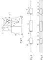
- FIG. 1 shows a highly schematic warp knitting machine 1 with a knitting area 2 and a fabric take-off 3.
- a knitted fabric 4 is formed from incoming threads of a warp, which is drawn off from the fabric take-off 3 from the knitting area 2.
- the tension with which the knitted fabric 4 is pulled off the knitted area 2 is a parameter with which the properties of the knitted fabric 4 can be influenced.
- the fabric take-off 3 has a plurality of rollers 5, 6, 7 over which the knitted fabric 4 is guided. These rollers 5-7 are rotatably mounted in a frame 8 of the warp knitting machine.
- the knitted fabric 4 can also be fed via a deflection roller 9, shown schematically, to a roll-up, which is not shown in detail.
- rollers 5-7 of the fabric deduction 3 rotate relatively slowly.
- knitting tools attached to bars work together. These bars must be moved in opposite directions at least once in each knitting operation.
- they are usually driven by a main shaft, which rotates in a machine bed 10 at a significantly higher speed than the rollers 5-7 of the goods take-off 3.
- vibrations arise here to a considerable extent vibrations that are transmitted from the machine bed 10 to the frame 8 and thus to the rollers 5-7 of the fabric deduction 3.
- These vibrations in turn excite the rollers 5-7 to vibrate. Vibrations of this type can have a negative effect on the quality of the knitted fabric 4 . Strong vibrations can also damage the rollers 5-7.
- an in 2 Vibration absorber arrangement 11 shown in more detail is provided.
- the vibration absorber arrangement is in 3 installed in a roller tube 12 shown.
- the roller tube 12 can belong to one of the rollers 5-7 and/or to the roller 9. It is also possible to provide a corresponding vibration damper arrangement 11 in two or even three of the rollers 5-7 of the goods take-off 3.
- the vibration damper arrangement 11 is designed as a passive vibration damper. It has an adapter 13 which is connected to the roller tube 12 .
- the adapter 13 can be pressed, welded, glued or screwed into the roller tube 12 .
- the adapter 13 is connected to a rod 14 .
- the rod 14 is passed through the adapter 13. It is also possible to use two rods 14 which protrude from the adapter 13 on both sides.
- the adapter 13 is connected via the rod 14 to a mass arrangement, which in the present case has two masses 15, 16, which can also be referred to as mass elements.
- the masses 15, 16 are arranged symmetrically to the adapter 13, ie they are the same distance from the adapter 13 and the same physical mass. However, deviations from a mathematically exact symmetry are possible. For example, the masses 15, 16 can have sizes that differ by up to 20%.
- the distances to the connection point on the roller tube 12 can differ by up to 20%.
- the vibration absorber arrangement 11 is connected to the roller in a middle, axial third of the roller tube 12, ie in a middle region of the roller tube 12. Ideally, a connection is made in the axial center, but this is not always possible.
- the spring arrangement can, for example, comprise a plurality of springs which are connected to the roller tube 12 and from which the mass or masses are suspended.
- the springs can be formed by elastomers, for example.
- a passive vibration damper or in addition to a passive vibration damper, you can also use an active vibration damper, which works with piezo elements, for example.
- piezo plates, piezo foils, piezo stack actuators or the like can be used as piezo elements.
- passive vibration absorbers with variable spring stiffness during operation.
- Such a vibration absorber is also referred to as an adaptive vibration absorber.
- a hybrid vibration absorber that works with 2 piezo foils, for example.
- One foil acts as a generator and another foil acts as an actuator. This converts vibrational energy into heat.
- the masses 15, 16 are cylindrical, square or with a polygonal cross section, which preferably has at least 8 corners. This is a simple way of making the mass distribution of the masses 15, 16 largely homogeneous in the circumferential direction.
- the homogeneity allows be defined, for example, in that any two longitudinal sections of the masses 15, 16 through the axis of the roller 5-7 deviate from one another by no more than 20% of the size of the cut surface.
- the rod 14 is also cylindrical or with a polygonal cross section, which preferably has at least 10 corners, so that the vibration damper arrangement 11 has practically the same vibration behavior in all radial directions and thus practically the same damping behavior. This is advantageous because reels 5-7 rotate during operation.
- the vibration absorber arrangement 11 is arranged symmetrically with respect to an axial center of the roller tube 12 and is connected to the roller tube 12 in the axial center of the roller.
- the roller tube 12 has a cavity 17 which has a cylindrical internal cross section. Accordingly, the masses 15, 16 with their cylindrical, square or polygonal outer contour are adapted to the inner contour of the cavity 17 in the best possible way and can utilize the cavity 17 as the best possible installation space.
- the rod 14 is designed as a threaded rod, i.e. it has an external thread.
- the masses 15, 16 are provided with threaded nuts 18, 19; 20, 21 provided. However, it is also possible to provide an internal thread directly in the masses 15, 16.
- the rod 14 has the function of a spring. At the same time, it has the function of a damper.
- a roller tube 12 is shown with a single vibration damper arrangement 11. It is also possible to use a plurality of vibration damper arrangements in a roller 5-7.
Landscapes
- Engineering & Computer Science (AREA)
- General Engineering & Computer Science (AREA)
- Mechanical Engineering (AREA)
- Textile Engineering (AREA)
- Physics & Mathematics (AREA)
- Acoustics & Sound (AREA)
- Aviation & Aerospace Engineering (AREA)
- Knitting Machines (AREA)
Abstract
Description
- Die vorliegende Erfindung betrifft eine Kettenwirkmaschine mit einem Wirkbereich und einem Warenabzug, der mindestens eine Walze aufweist.
- Eine Kettenwirkmaschine dient zur Erzeugung von Wirkwaren. Bei der Erzeugung einer Wirkware erfolgt im Wirkbereich ein Maschenbildungsvorgang, bei dem parallel zulaufende Fäden einer Kette durch Bildung von Maschen miteinander verbunden werden. Das so entstandene Flächengebilde wird über den Warenabzug abgezogen. Der Warenabzug weist hierbei mindestens eine, jedoch in der Regel mehrere Walzen auf, über die die Wirkware geführt wird. Durch eine Änderung der Spannung, mit der der Warenabzug die Wirkware abzieht, kann auch das Erscheinungsbild der Wirkware verändert werden.
- Bei Kettenwirkmaschinen geht die Entwicklung einerseits zu einer immer höheren Arbeitsgeschwindigkeit. Die Arbeitsgeschwindigkeit wird auch mit "Nenndrehzahl" bezeichnet. Andererseits geht die Entwicklung zu immer größeren Arbeitsbreiten der Kettenwirkmaschine. Es ist jedoch schwierig, beide Parameter, also eine höhere Nenndrehzahl und eine größere Arbeitsbreite, miteinander zu kombinieren. Je größer die Arbeitsgeschwindigkeit oder Nenndrehzahl der Kettenwirkmaschine ist, desto stärkere Probleme ergeben sich mit Schwingungen. Diese Probleme werden um so größer, je größer die Arbeitsbreite der Kettenwirkmaschine ist. Wenn die Walze oder die Walzen des Warenabzugs schwingen, hat dies einen negativen Einfluss auf die Qualität der Wirkware.
- Der Erfindung liegt die Aufgabe zugrunde, eine Kettenwirkmaschine mit hoher Produktivität bereitzustellen.
- Diese Aufgabe wird bei einer Kettenwirkmaschine der eingangs genannten Art dadurch gelöst, dass die Walze eine Schwingungstilgeranordnung aufweist.
- Wenn man die Arbeitsbreite der Kettenwirkmaschine vergrößert, dann vergrößert sich in gleicher Weise die axiale Länge der Walzen. Die Walzen werden damit schlanker und sind damit empfindlicher gegenüber Schwingungen. Dies lässt sich nur teilweise dadurch kompensieren, dass man die Masse der Walzen erhöht, z.B. indem man sie mit schwerem Material befüllt, oder die Steifigkeit erhöht, z.B. durch Erhöhen der Wandstärke oder des Durchmessers. Diese Maßnahmen haben darüber hinaus den Nachteil, dass sie eine Wartung der Kettenwirkmaschine erschweren, weil dabei jedenfalls gelegentlich der Warenabzug entfernt werden muss.
- Durch die Verwendung einer Schwingungstilgeranordnung werden nun Schwingungen, die bei der Nenndrehzahl der Kettenwirkmaschine auftreten, zumindest teilweise absorbiert. Es entstehen zwar zwei neue Resonanzfrequenzen. Diese haben jedoch dann einen geringeren Schwingweg.
- Vorzugsweise ist die Walze als Walzenrohr mit einem Hohlraum ausgebildet und die Schwingungstilgeranordnung ist im Hohlraum angeordnet. Die Schwingungstilgeranordnung benötigt also keinen zusätzlichen Bauraum. Die Schwingungstilgeranordnung kann jedoch dort angeordnet werden, wo ohne weitere Maßnahmen die größten Schwingungen auftreten würden.
- Vorzugsweise ist die Schwingungstilgeranordnung symmetrisch in Bezug zu einer axialen Mitte der Walze angeordnet. Damit lässt sich die Schwingungstilgung auf den Bereich der axialen Mitte konzentrieren. Der Begriff "symetrisch" ist hier nicht im mathematisch engen Sinne zu verstehen. Abweichungen von einer exakten Symmetrie sind bis zu 20% zulässig.
- Dies ist in einer bevorzugten Weise auf einfache Weise dadurch möglich, dass die Schwingungstilgeranordnung zumindest in einem mittleren axialen Drittel mit der Walze verbunden ist. Die Schwingungstilgeranordnung ist dann etwa in der axialen Mitte der Walze mit der Walze verbunden, also dort, wo die größte Schwingungsamplitude auftritt. Dementsprechend ist die Tilgerwirkung oder Dämpferwirkung am größten.
- Vorzugsweise weist die Schwingungstilgeranordnung mindestens einen passiven Schwingungstilger auf. Damit ist die Zufuhr einer Hilfsenergie von außen nicht erforderlich. Die Schwingungstilgeranordnung wird durch eine Scheingung von außen angeregt und entzieht dadurch der Schwingung Energie.
- Alternativ oder zusätzlich kann vorgesehen sein, dass die Schwingungstilgeranordnung mindestens einen aktiven, hybriden und/oder adaptiven Schwingungstilger aufweist. Ein aktiver Schwingungstilger kann beispielsweise Piezoelemente, wie Piezoplatten, Piezofolien, Piezostapelaktoren oder dergleichen enthalten. Ein adaptiver Schwingungstilger kann ein passiver Schwingungstilger mit einer im Betrieb veränderbaren Frequenz sein. Ein hybrider Schwingungstilger beispielsweise mit zwei Piezofolien ausgebildet sein, von denen eine als Generator und eine als Aktor wirkt, Dadurch wird Schwinungsenergie in Wärme umgewandelt. Derartige Schwingungstilger können auch zusätzlich zu einem rein passiven Schwingungstilger eingesetzt werden.
- Vorzugsweise weist der Schwingungstilger eine über eine Federanordnung mit dem Walzenrohr verbundene Massenanordnung auf, wobei die Verbindung insbesondere über einen Adapter erfolgt. Der Adapter kann beispielsweise in das Walzenrohr eingepresst, eingeklebt, eingeschweißt oder verschraubt sein. Durch die direkte Verbindung oder die Verbindung über den Adapter wird die Schwingung des Walzenrohres unmittelbar in den Schwingungstilger eingeleitet. Die Schwingung wird dann über die Federanordnung auf die Massenanordnung übertragen, die ihrerseits schwingt und zwar etwa in Gegenphase zur anregenden Schwingung und dadurch der Schwingung des Walzenrohres Energie entzieht.
- Vorzugsweise weichen zwei beliebige Längsschnitte der Massenanordnung durch die Achse der Walze um nicht mehr als 20% der Schnittflächengröße voneinander ab. Die Massenanordnung weist also eine in Umfangsrichtung um die Achse der Walze weitgehend homogene Massenverteilung auflm Idealfall ist die Massenverteilung in Umfangsrichtung homogen, was sich allerdings vielfach nicht mit vertretbarem Aufwand realisieren lässt. Die weitgehend homogene Massenverteilung ist ein Beitrag dazu, Schwingungen in alle Richtungen quer zur Achse der Walze gleichartig zu dämpfen. Auch bei einer Rotation der Walze werden die Schwingungen zuverlässig gedämpft.
- Vorzugsweise weist die Federanordnung eine Stange auf, die sich in axialer Richtung der Walze erstreckt. Die Stange bildet dann eine Art Feder oder hat zumindest die Funktion einer Feder mit einer definierten Nachgiebigkeit.
- Vorzugsweise weist die Stange einen zylindrischen oder quadratischen Querschnitt oder einen mehreckigen Querschnitt mit mindestens 8 Ecken auf. Damit ist ihr Verformungsverhalten in alle radialen Richtungen (bezogen auf eine Achse des Walzenrohrs) praktisch gleich. Dies ist ein weiterer Beitrag dazu, der Tilgeranordnung in alle radialen Richtungen die gleiche Dämpfungs- oder Tilgungswirkung mitzugeben.
- Vorzugsweise weist die Massenanordnung mindestens zwei Massen auf, die beidseits des Adapters an der Stange befestigt sind. Wenn Schwingungen in das Walzenrohr eingetragen werden, dann werden diese Schwingungen über die Stange an die beiden Massen übertragen, die dann im Idealfall im Gegentakt zur Schwingung des Walzenrohres schwingen und damit die Schwingungen bei Nenndrehzahl tilgen.
- Vorzugsweise weisen die Massen eine an die Innenkontur des Hohlraums angepasste Außenkontur auf. Dadurch wird der Hohlraum innerhalb des Walzenrohrs bestmöglich ausgenutzt. Insbesondere können die Massen eine zylindrische Außenkontur aufweisen. Üblicherweise weist ein Walzenrohr einen zylindrischen Innenraum auf. Die Ausbildung mit einer zylindrischen Außenkontur hat darüber hinaus die Vorteile, dass man die Massenverteilung in Umfangsrichtung weitgehend homogen gestalten kann, ohne einen großen Aufwand betreiben zu müssen. Kleine Abweichung von der Zylinderform, beispielsweise eine mehreckige Form oder eine andere Konturierung sind akzeptabel.
- . Vorzugsweise sind die Massen an unterschiedlichen Positionen auf der Stange festlegbar. Damit können die Massen so positioniert werden, dass sie auf die Eigenfrequenz der jeweiligen Walze oder des Gesamtsystems aus mehreren Walzen abgestimmt sind. Man kann damit auch eine Feinabstimmung vornehmen. Wenn die Massen positioniert worden sind, können sie an den Stangen so befestigt werden, dass ihre Position nicht mehr oder nicht mehr ohne weiteres verändert werden kann.
- Vorzugsweise ist die Stange als Gewindestange ausgebildet. Eine Gewindestange ist ein handelsübliches Bauelement, das wenig zusätzliche Kosten verursacht. Eine Gewindestange weist ein Außengewinde auf. Dieses Außengewinde kann verwendet werden, um die Massen an bestimmten Positionen festzulegen. Zum Festlegen kann man beispielsweise Muttern verwenden, die gegen die Massen geschraubt werden. Alternativ dazu können die Massen ein Innengewinde aufweisen. Man kann durch ein Verdrehen der Massen auf der Gewindestange die Position der Massen festlegen. Gegebenenfalls kann die Position der Masse auf der Gewindestange dann durch eine Kontermutter gesichert werden.
- Die Erfindung wird im Folgenden anhand eines bevorzugten Ausführungsbeispiels in Verbindung mit der Zeichnung beschrieben. Hierin zeigen:
- Fig. 1
- eine stark schematisierte Darstellung einer Kettenwirkmaschine,
- Fig. 2
- eine Schwingungstilgeranordnung und
- Fig. 3
- die Schwingungstilgeranordnung eingebaut in eine Walze.
-
Fig. 1 zeigt stark schematisiert eine Kettenwirkmaschine 1 mit einem Wirkbereich 2 und einem Warenabzug 3. Im Wirkbereich 2 wird aus zulaufenden Fäden einer Kette eine Wirkware 4 gebildet, die vom Warenabzug 3 aus dem Wirkbereich 2 abgezogen wird. Die Spannung, mit der die Wirkware 4 aus dem Wirkbereich 2 abgezogen wird, ist ein Parameter, mit dem Eigenschaften der Wirkware 4 beeinflusst werden können. - Der Warenabzug 3 weist mehrere Walzen 5, 6, 7 auf, über die die Wirkware 4 geführt wird. Diese Walzen 5-7 sind in einem Rahmen 8 der Kettenwirkmaschine drehbar gelagert.
- Die Wirkware 4 kann über eine schematisch dargestellte Umlenkwalze 9 noch einer nicht näher dargestellten Aufrollung zugeführt werden.
- Die Walzen 5-7 des Warenabzugs 3 drehen sich relativ langsam. Im Wirkbereich 2 arbeiten jedoch Wirkwerkzeuge zusammen, die an Barren befestigt sind. Diese Barren müssen bei jedem Maschenbildungsvorgang mindestens einmal in entgegengesetzte Richtungen bewegt werden. Hierzu werden sie üblicherweise von einer Hauptwelle angetrieben, die in einem Maschinenbett 10 mit einer wesentlich größeren Drehzahl als die Walzen 5-7 des Warenabzugs 3 rotiert. Hierbei entstehen in erheblichem Maße Schwingungen, die vom Maschinenbett 10 auf den Rahmen 8 und damit auf die Walzen 5-7 des Warenabzugs 3 übertragen werden. Diese Schwingungen wiederum regen die Walzen 5-7 zu Schwingungen an. Derartige Schwingungen können sich negativ auf die Qualität der Wirkware 4 auswirken. Starke Schwingungen können darüber hinaus zur Beschädigung der Walzen 5-7 führen.
- Um Schwingungen im Warenabzug 3 entgegenzuwirken und dabei zu ermöglichen, dass die Kettenwirkmaschine 1 eine große Arbeitsbreite aufweist und gleichzeitig mit einer hohen Nenndrehzahl betrieben werden kann, ist eine in
Fig. 2 näher dargestellte Schwingungstilgeranordnung 11 vorgesehen. Die Schwingungstilgeranordnung ist inFig. 3 eingebaut in ein Walzenrohr 12 dargestellt. Das Walzenrohr 12 kann zu einer der Walzen 5-7 und/oder zu der Rolle 9 gehören. Es ist auch möglich, in zwei oder sogar drei der Walzen 5-7 des Warenabzugs 3 eine entsprechende Schwingungstilgeranordnung 11 vorzusehen. - Die Schwingungstilgeranordnung 11 ist im vorliegenden Ausführungsbeispiel als passiver Schwingungstilger ausgebildet. Sie weist einen Adapter 13 auf, der mit dem Walzenrohr 12 verbunden ist. Der Adapter 13 kann in das Walzenrohr 12 eingepresst, eingeschweißt, eingeklebt oder hier verschraubt sein. Der Adapter 13 ist mit einer Stange 14 verbunden. Im vorliegenden Ausführungsbeispiel ist die Stange 14 durch den Adapter 13 hindurchgeführt. Es ist auch möglich, zwei Stangen 14 zu verwenden, die auf beiden Seiten des Adapters 13 aus dem Adapter 13 herausragen. Der Adapter 13 ist über die Stange 14 mit einer Massenanordnung verbunden, die im vorliegenden Fall zwei Massen 15, 16, die auch als Massenelement bezeichnet werden können, aufweisen. Die Massen 15, 16 sind symmetrisch zum Adapter 13 angeordnet, d.h. sie haben die gleiche Entfernung zum Adapter 13 und die gleiche physikalische Masse. Abweichungen von einer mathematisch exakten Symmetrie sind allerdings möglich. So können die Massen 15, 16 beispielsweise Größen haben, die sich um bis zu 20 % unterscheiden.
- Auch die Entfernungen zum Anbindungspunkt am Walzenrohr 12 können sich um bis zu 20 % unterscheiden.
- Die Schwingungstilgeranordnung 11 ist in einem mittleren axialen Drittel des Walzenrohres 12, also in einem Mittelbereich des Walzenrohres 12 mit der Walze verbunden. Im Idealfall erfolgt eine Verbindung in der axialen Mitte, was sich aber nicht immer realisieren lässt.
- Es ist auch möglich, die Massen 15, 16 oder auch nur eine einzelne Masse über eine Federanordnung unmittelbar mit dem Walzenrohr 12 zu verbinden. In diesem Fall kann die Federanordnung beispielsweise mehrere Federn aufweisen, die mit dem Walzenrohr 12 verbunden sind und an denen die Masse oder die Massen aufgehängt sind. Die Federn können beispielsweise durch Elastomere gebildet sein.
- Anstelle eines passiven Schwingungstilger oder zusätzlich zu einem passiven Schwingungstilger kann man auch einen aktiven Schwingungstilger verwenden, der beispielsweise mit Piezo-Elementen arbeitet. Als Piezo-Elemente kann man beispielsweise Piezo-Platten, Piezo-Folien, Piezo-Stapelaktoren oder dergleichen verwenden. Man kann auch passive Schwingungstilger mit veränderlicher Federsteifigkeit im Betrieb verwenden. Ein derartiger Schwingungstilger wird auch als adaptiver Schwingungstilger bezeichnet. Es ist auch möglich, einen hybriden Schwingungstilger zu verwenden, der beispielsweise mit 2 Piezo-Folien arbeitet. Eine Folie wirkt dabei als Generator und eine andere Folie wirkt als Aktor. Dadurch wird Schwinungsenergie in Wärme umgewandelt.
- Die Massen 15, 16 sind zylinderförmig, quadratisch oder mit einem polygonförmigen Querschnitt, der vorzugsweise mindestens 8 Ecken aufweist, ausgebildet. Dies ist eine einfache Möglichkeit, um die Massenverteilung der Massen 15, 16 in Umfangsrichtung weitgehend homogen zu gestalten. Die Homogenität lässt sich beispielsweise dadurch definieren, dass zwei beliebige Längschnitte der Massen 15, 16 durch die Achse der Walze 5-7 um nicht mehr als 20% der Schnittflächengröße voneinander abweichen.
- Auch die Stange 14 ist zylinderförmig oder mit einem polygonförmigen Querschnitt, der vorzugsweise mindestens 10 Ecken aufweist, ausgebildet, so dass die Schwingungstilgeranordnung 11 in allen radialen Richtungen praktisch das gleiche Schwingungsverhalten und damit praktisch das gleiche Tilgungsverhalten aufweist. Dies ist von Vorteil, weil sich die Walzen 5-7 in Betrieb drehen.
- Wie man anhand von
Fig. 3 erkennen kann, ist die Schwingungstilgeranordnung 11 symmetrisch in Bezug zu einer axialen Mitte des Walzenrohres 12 angeordnet und in der axialen Mitte der Walze mit dem Walzenrohr 12 verbunden. - Das Walzenrohr 12 weist einen Hohlraum 17 auf, der einen zylindrischen Innenquerschnitt aufweist. Dementsprechend sind die Massen 15, 16 mit ihrer zylindrischen, quadratischen oder mehreckigen Außenkontur bestmöglich an die Innenkontur des Hohlraums 17 angepasst und können den Hohlraum 17 als Bauraum bestmöglich ausnutzen.
- Die Stange 14 ist als Gewindestange ausgebildet, d.h. sie weist ein Außengewinde auf. Im vorliegenden Ausführungsbeispiel sind die Massen 15, 16 an ihren beiden Stirnseiten mit Gewindemuttern 18, 19; 20, 21 versehen. Es ist jedoch auch möglich, ein Innengewinde unmittelbar in den Massen 15, 16 vorzusehen.
- Die Stange 14 hat die Funktion einer Feder. Sie hat gleichzeitig die Funktion eines Dämpfers.
- Dargestellt ist ein Walzenrohr 12 mit einer einzigen Schwingungstilgeranordnung 11. Es ist auch möglich, mehrere Schwingungstilgeranordnungen in einer Walze 5-7 zu verwenden.
Claims (15)
- Kettenwirkmaschine (1) mit einem Wirkbereich (2) und einem Warenabzug (3), der mindestens eine Walze (5-7) aufweist, dadurch gekennzeichnet, dass die Walze (5-7) eine Schwingungstilgeranordnung (11) aufweist.
- Kettenwirkmaschine nach Anspruch 1, dadurch gekennzeichnet, dass die Walze (5-7) als Walzenrohr (12) mit einem Hohlraum (17) ausgebildet ist und die Schwingungstilgeranordnung (11) im Hohlraum (17) angeordnet ist.
- Kettenwirkmaschine nach Anspruch 1 oder 2, dadurch gekennzeichnet, dass die Schwingungstilgeranordnung (11) symmetrisch in Bezug zu einer axialen Mitte der Walze (5-7) angeordnet ist.
- Kettenwirkmaschine nach einem der Ansprüche 1 bis 3, dadurch gekennzeichnet, dass die Schwingungstilgeranordnung (11) zumindest in einem mittleren axialen Drittel der Walze (5-7) mit der Walze (5-7) verbunden ist.
- Kettenwirkmaschine nach einem der Ansprüche 1 bis 4, dadurch gekennzeichnet, dass die Schwingungstilgeranordnung (11) mindestens einen passiven Schwingungstilger aufweist.
- Kettenwirkmaschine nach einem der Ansprüche 1 bis 5, dadurch gekennzeichnet, dass die Schwingungstilgeranordnung (11) mindestens einen aktiven, hybriden und/oder adaptiven Schwingungstilger aufweist.
- Kettenwirkmaschine nach Anspruch 5 oder 6, dadurch gekennzeichnet, dass der Schwingunstilger eine über eine Federanordnung mit dem Walzenrohr (12) verbundene Massenanordnung aufweist, wobei die Verbindung insbesondere über einen Adapter (13) erfolgt.
- Kettenwirkmaschine nach Anspruch 7, dadurch gekennzeichnet, dass zwei beliebige Längsschnitte der Massenanordnung durch die Achse der Walze (5-7) um nicht mehr als 20% der Schnittflächengröße voneinander abweichen.
- Kettenwirkmaschine nach Anspruch 7 oder 8, dadurch gekennzeichnet, dass die Federanordnung eine Stange (14) aufweist, die sich in axialer Richtung der Walze (5-7) erstreckt.
- Kettenwirkmaschine nach Anspruch 9, dadurch gekennzeichnet, dass die Stange (14) einen zylindrischen oder quadratischen Querschnitt oder einen mehreckigen Querschnitt mit mindestens 8 Ecken aufweist.
- Kettenwirkmaschine nach einem der Ansprüche 6 bis 10, dadurch gekennzeichnet, dass die Massenanordnung mindestens zwei Massen (15, 16) aufweist, die beidseits des Adapters (13) an der Stange (14) befestigt sind.
- Kettenwirkmaschine nach Anspruch 11, dadurch gekennzeichnet, dass die Massen (15, 16) eine an die Innenkontur des Hohlraums (17) angepasste Außenkontur aufweisen.
- Kettenwirkmaschine nach Anspruch 11 oder 12, dadurch gekennzeichnet, dass die Masse (15, 16) eine zylindrische Außenkontur aufweisen.
- Kettenwirkmaschine nach einem der Ansprüche 11 bis 13, dadurch gekennzeichnet, dass die Massen (15, 16) an unterschiedlichen Positionen auf der Stange (14) festlegbar sind.
- Kettenwirkmaschine nach Anspruch 14, dadurch gekennzeichnet, dass die Stange (14) als Gewindestange ausgebildet ist.
Priority Applications (2)
| Application Number | Priority Date | Filing Date | Title |
|---|---|---|---|
| EP20192026.1A EP3957788B1 (de) | 2020-08-20 | 2020-08-20 | Kettenwirkmaschine |
| CN202110102278.XA CN114075713B (zh) | 2020-08-20 | 2021-01-26 | 经编机 |
Applications Claiming Priority (1)
| Application Number | Priority Date | Filing Date | Title |
|---|---|---|---|
| EP20192026.1A EP3957788B1 (de) | 2020-08-20 | 2020-08-20 | Kettenwirkmaschine |
Publications (2)
| Publication Number | Publication Date |
|---|---|
| EP3957788A1 true EP3957788A1 (de) | 2022-02-23 |
| EP3957788B1 EP3957788B1 (de) | 2024-07-03 |
Family
ID=72178483
Family Applications (1)
| Application Number | Title | Priority Date | Filing Date |
|---|---|---|---|
| EP20192026.1A Active EP3957788B1 (de) | 2020-08-20 | 2020-08-20 | Kettenwirkmaschine |
Country Status (2)
| Country | Link |
|---|---|
| EP (1) | EP3957788B1 (de) |
| CN (1) | CN114075713B (de) |
Citations (6)
| Publication number | Priority date | Publication date | Assignee | Title |
|---|---|---|---|---|
| EP1411254A1 (de) * | 2002-10-17 | 2004-04-21 | Voith Paper Patent GmbH | Walze, insbesondere Mittelwalze eines Kalanders, mit einer Tilgeranordnung |
| DE102004000038A1 (de) * | 2003-11-13 | 2005-07-28 | Cetex Chemnitzer Textilmaschinenentwicklung Ggmbh | Schwingungsgemindertes Maschinenelement wie Walze oder Traverse |
| EP1731669A1 (de) * | 2005-06-10 | 2006-12-13 | Voith Patent GmbH | Biegeausgleichswalze |
| DE102007031090A1 (de) * | 2006-07-17 | 2008-01-24 | Metso Paper, Inc. | Schwingungssteuerung in einem Papierkalander |
| EP1936214A2 (de) * | 2006-12-22 | 2008-06-25 | Andritz Küsters GmbH | Walze mit Schwingungsdämpfer sowie Verfahren zur Dämpfung von Schwingungen einer Walze |
| DE102010046587A1 (de) * | 2010-09-25 | 2012-03-29 | Karl Mayer China Ltd. | Wirkmaschine |
Family Cites Families (1)
| Publication number | Priority date | Publication date | Assignee | Title |
|---|---|---|---|---|
| GB795532A (en) * | 1955-02-04 | 1958-05-28 | F N F Machinery Mfg Company Lt | Improvements relating to warp knitting machines |
-
2020
- 2020-08-20 EP EP20192026.1A patent/EP3957788B1/de active Active
-
2021
- 2021-01-26 CN CN202110102278.XA patent/CN114075713B/zh active Active
Patent Citations (6)
| Publication number | Priority date | Publication date | Assignee | Title |
|---|---|---|---|---|
| EP1411254A1 (de) * | 2002-10-17 | 2004-04-21 | Voith Paper Patent GmbH | Walze, insbesondere Mittelwalze eines Kalanders, mit einer Tilgeranordnung |
| DE102004000038A1 (de) * | 2003-11-13 | 2005-07-28 | Cetex Chemnitzer Textilmaschinenentwicklung Ggmbh | Schwingungsgemindertes Maschinenelement wie Walze oder Traverse |
| EP1731669A1 (de) * | 2005-06-10 | 2006-12-13 | Voith Patent GmbH | Biegeausgleichswalze |
| DE102007031090A1 (de) * | 2006-07-17 | 2008-01-24 | Metso Paper, Inc. | Schwingungssteuerung in einem Papierkalander |
| EP1936214A2 (de) * | 2006-12-22 | 2008-06-25 | Andritz Küsters GmbH | Walze mit Schwingungsdämpfer sowie Verfahren zur Dämpfung von Schwingungen einer Walze |
| DE102010046587A1 (de) * | 2010-09-25 | 2012-03-29 | Karl Mayer China Ltd. | Wirkmaschine |
Also Published As
| Publication number | Publication date |
|---|---|
| CN114075713B (zh) | 2023-09-22 |
| CN114075713A (zh) | 2022-02-22 |
| EP3957788B1 (de) | 2024-07-03 |
Similar Documents
| Publication | Publication Date | Title |
|---|---|---|
| EP2565310B1 (de) | Kettenwirkmaschine | |
| EP3227579B1 (de) | Adaptiver pendeltilger mit vertikaler federvorrichtung | |
| DE1511224C3 (de) | Walze mit feststehender hohler Tragachse | |
| EP3155287A1 (de) | Torsionsbelastetes stabförmiges bauteil mit unterschiedlichen faserverstärkungen für zug- und druckbelastung | |
| DE102011000858A1 (de) | Statorkernaufhängungssystem unter Verwendung von Federstäben in einer sich senkrecht zu der Statorkernachse erstreckenden Ebene | |
| EP3081681B1 (de) | Wirkwerkzeugbarre | |
| EP3132155A1 (de) | Torsionsbelastetes stabförmiges bauteil | |
| DE102010046587B4 (de) | Wirkmaschine | |
| EP2949612B1 (de) | Spulvorrichtung für eine kreuzspulen herstellende textilmaschine | |
| EP3957788B1 (de) | Kettenwirkmaschine | |
| EP2230343B1 (de) | Wirkwerkzeugbarre | |
| EP3859067B1 (de) | Kettenwirkmaschine | |
| EP4034782B1 (de) | An einer rahmenkonstruktion elastisch befestigte elektrische maschine | |
| EP3159443B1 (de) | Kettenwirkmaschine | |
| DE4235421C1 (de) | ||
| EP1790600B1 (de) | Rollenwickeleinrichtung | |
| EP2502860B1 (de) | Vorrichtung zum Aufwickeln einer Materialbahn | |
| EP3449149A1 (de) | In einer richtung wirksamer adaptiver schwingungstilger | |
| EP2161372A2 (de) | Trockenpartie | |
| DE112011103576B4 (de) | Walzenstützanordnung einer Faserbahnmaschine und Teilbahnwickler einer Faserbahnrollenschneidmaschine | |
| DE102006023831A1 (de) | Rollenwickeleinrichtung | |
| DE19938872A1 (de) | Kettenwirkmaschine mit Fadenschar-Umlenkvorrichtung | |
| DE1750384A1 (de) | Stuetzrolle | |
| EP3133195B1 (de) | Fadenspanneinrichtung | |
| AT222611B (de) | Elastische Lagerung der Trommelgehäuse von Wasch- und Scleudermaschinen |
Legal Events
| Date | Code | Title | Description |
|---|---|---|---|
| PUAI | Public reference made under article 153(3) epc to a published international application that has entered the european phase |
Free format text: ORIGINAL CODE: 0009012 |
|
| STAA | Information on the status of an ep patent application or granted ep patent |
Free format text: STATUS: THE APPLICATION HAS BEEN PUBLISHED |
|
| AK | Designated contracting states |
Kind code of ref document: A1 Designated state(s): AL AT BE BG CH CY CZ DE DK EE ES FI FR GB GR HR HU IE IS IT LI LT LU LV MC MK MT NL NO PL PT RO RS SE SI SK SM TR |
|
| STAA | Information on the status of an ep patent application or granted ep patent |
Free format text: STATUS: REQUEST FOR EXAMINATION WAS MADE |
|
| 17P | Request for examination filed |
Effective date: 20220228 |
|
| RBV | Designated contracting states (corrected) |
Designated state(s): AL AT BE BG CH CY CZ DE DK EE ES FI FR GB GR HR HU IE IS IT LI LT LU LV MC MK MT NL NO PL PT RO RS SE SI SK SM TR |
|
| STAA | Information on the status of an ep patent application or granted ep patent |
Free format text: STATUS: EXAMINATION IS IN PROGRESS |
|
| 17Q | First examination report despatched |
Effective date: 20230220 |
|
| P01 | Opt-out of the competence of the unified patent court (upc) registered |
Effective date: 20230705 |
|
| GRAP | Despatch of communication of intention to grant a patent |
Free format text: ORIGINAL CODE: EPIDOSNIGR1 |
|
| STAA | Information on the status of an ep patent application or granted ep patent |
Free format text: STATUS: GRANT OF PATENT IS INTENDED |
|
| INTG | Intention to grant announced |
Effective date: 20240313 |
|
| GRAS | Grant fee paid |
Free format text: ORIGINAL CODE: EPIDOSNIGR3 |
|
| GRAA | (expected) grant |
Free format text: ORIGINAL CODE: 0009210 |
|
| STAA | Information on the status of an ep patent application or granted ep patent |
Free format text: STATUS: THE PATENT HAS BEEN GRANTED |
|
| AK | Designated contracting states |
Kind code of ref document: B1 Designated state(s): AL AT BE BG CH CY CZ DE DK EE ES FI FR GB GR HR HU IE IS IT LI LT LU LV MC MK MT NL NO PL PT RO RS SE SI SK SM TR |
|
| REG | Reference to a national code |
Ref country code: CH Ref legal event code: EP |
|
| REG | Reference to a national code |
Ref country code: DE Ref legal event code: R096 Ref document number: 502020008431 Country of ref document: DE |
|
| REG | Reference to a national code |
Ref country code: LT Ref legal event code: MG9D |
|
| PGFP | Annual fee paid to national office [announced via postgrant information from national office to epo] |
Ref country code: IT Payment date: 20240926 Year of fee payment: 5 |
|
| REG | Reference to a national code |
Ref country code: NL Ref legal event code: MP Effective date: 20240703 |
|
| PGFP | Annual fee paid to national office [announced via postgrant information from national office to epo] |
Ref country code: TR Payment date: 20240826 Year of fee payment: 5 |
|
| PG25 | Lapsed in a contracting state [announced via postgrant information from national office to epo] |
Ref country code: PT Free format text: LAPSE BECAUSE OF FAILURE TO SUBMIT A TRANSLATION OF THE DESCRIPTION OR TO PAY THE FEE WITHIN THE PRESCRIBED TIME-LIMIT Effective date: 20241104 |
|
| PG25 | Lapsed in a contracting state [announced via postgrant information from national office to epo] |
Ref country code: NL Free format text: LAPSE BECAUSE OF FAILURE TO SUBMIT A TRANSLATION OF THE DESCRIPTION OR TO PAY THE FEE WITHIN THE PRESCRIBED TIME-LIMIT Effective date: 20240703 |
|
| PG25 | Lapsed in a contracting state [announced via postgrant information from national office to epo] |
Ref country code: PT Free format text: LAPSE BECAUSE OF FAILURE TO SUBMIT A TRANSLATION OF THE DESCRIPTION OR TO PAY THE FEE WITHIN THE PRESCRIBED TIME-LIMIT Effective date: 20241104 Ref country code: NL Free format text: LAPSE BECAUSE OF FAILURE TO SUBMIT A TRANSLATION OF THE DESCRIPTION OR TO PAY THE FEE WITHIN THE PRESCRIBED TIME-LIMIT Effective date: 20240703 |
|
| PG25 | Lapsed in a contracting state [announced via postgrant information from national office to epo] |
Ref country code: NO Free format text: LAPSE BECAUSE OF FAILURE TO SUBMIT A TRANSLATION OF THE DESCRIPTION OR TO PAY THE FEE WITHIN THE PRESCRIBED TIME-LIMIT Effective date: 20241003 |
|
| PG25 | Lapsed in a contracting state [announced via postgrant information from national office to epo] |
Ref country code: FI Free format text: LAPSE BECAUSE OF FAILURE TO SUBMIT A TRANSLATION OF THE DESCRIPTION OR TO PAY THE FEE WITHIN THE PRESCRIBED TIME-LIMIT Effective date: 20240703 Ref country code: GR Free format text: LAPSE BECAUSE OF FAILURE TO SUBMIT A TRANSLATION OF THE DESCRIPTION OR TO PAY THE FEE WITHIN THE PRESCRIBED TIME-LIMIT Effective date: 20241004 Ref country code: PL Free format text: LAPSE BECAUSE OF FAILURE TO SUBMIT A TRANSLATION OF THE DESCRIPTION OR TO PAY THE FEE WITHIN THE PRESCRIBED TIME-LIMIT Effective date: 20240703 |
|
| PG25 | Lapsed in a contracting state [announced via postgrant information from national office to epo] |
Ref country code: BG Free format text: LAPSE BECAUSE OF FAILURE TO SUBMIT A TRANSLATION OF THE DESCRIPTION OR TO PAY THE FEE WITHIN THE PRESCRIBED TIME-LIMIT Effective date: 20240703 |
|
| PG25 | Lapsed in a contracting state [announced via postgrant information from national office to epo] |
Ref country code: LV Free format text: LAPSE BECAUSE OF FAILURE TO SUBMIT A TRANSLATION OF THE DESCRIPTION OR TO PAY THE FEE WITHIN THE PRESCRIBED TIME-LIMIT Effective date: 20240703 |
|
| PG25 | Lapsed in a contracting state [announced via postgrant information from national office to epo] |
Ref country code: IS Free format text: LAPSE BECAUSE OF FAILURE TO SUBMIT A TRANSLATION OF THE DESCRIPTION OR TO PAY THE FEE WITHIN THE PRESCRIBED TIME-LIMIT Effective date: 20241103 |
|
| PG25 | Lapsed in a contracting state [announced via postgrant information from national office to epo] |
Ref country code: HR Free format text: LAPSE BECAUSE OF FAILURE TO SUBMIT A TRANSLATION OF THE DESCRIPTION OR TO PAY THE FEE WITHIN THE PRESCRIBED TIME-LIMIT Effective date: 20240703 Ref country code: CZ Free format text: LAPSE BECAUSE OF FAILURE TO SUBMIT A TRANSLATION OF THE DESCRIPTION OR TO PAY THE FEE WITHIN THE PRESCRIBED TIME-LIMIT Effective date: 20240703 |
|
| PG25 | Lapsed in a contracting state [announced via postgrant information from national office to epo] |
Ref country code: ES Free format text: LAPSE BECAUSE OF FAILURE TO SUBMIT A TRANSLATION OF THE DESCRIPTION OR TO PAY THE FEE WITHIN THE PRESCRIBED TIME-LIMIT Effective date: 20240703 Ref country code: RS Free format text: LAPSE BECAUSE OF FAILURE TO SUBMIT A TRANSLATION OF THE DESCRIPTION OR TO PAY THE FEE WITHIN THE PRESCRIBED TIME-LIMIT Effective date: 20241003 |
|
| PG25 | Lapsed in a contracting state [announced via postgrant information from national office to epo] |
Ref country code: RS Free format text: LAPSE BECAUSE OF FAILURE TO SUBMIT A TRANSLATION OF THE DESCRIPTION OR TO PAY THE FEE WITHIN THE PRESCRIBED TIME-LIMIT Effective date: 20241003 Ref country code: PL Free format text: LAPSE BECAUSE OF FAILURE TO SUBMIT A TRANSLATION OF THE DESCRIPTION OR TO PAY THE FEE WITHIN THE PRESCRIBED TIME-LIMIT Effective date: 20240703 Ref country code: NO Free format text: LAPSE BECAUSE OF FAILURE TO SUBMIT A TRANSLATION OF THE DESCRIPTION OR TO PAY THE FEE WITHIN THE PRESCRIBED TIME-LIMIT Effective date: 20241003 Ref country code: LV Free format text: LAPSE BECAUSE OF FAILURE TO SUBMIT A TRANSLATION OF THE DESCRIPTION OR TO PAY THE FEE WITHIN THE PRESCRIBED TIME-LIMIT Effective date: 20240703 Ref country code: IS Free format text: LAPSE BECAUSE OF FAILURE TO SUBMIT A TRANSLATION OF THE DESCRIPTION OR TO PAY THE FEE WITHIN THE PRESCRIBED TIME-LIMIT Effective date: 20241103 Ref country code: HR Free format text: LAPSE BECAUSE OF FAILURE TO SUBMIT A TRANSLATION OF THE DESCRIPTION OR TO PAY THE FEE WITHIN THE PRESCRIBED TIME-LIMIT Effective date: 20240703 Ref country code: GR Free format text: LAPSE BECAUSE OF FAILURE TO SUBMIT A TRANSLATION OF THE DESCRIPTION OR TO PAY THE FEE WITHIN THE PRESCRIBED TIME-LIMIT Effective date: 20241004 Ref country code: FI Free format text: LAPSE BECAUSE OF FAILURE TO SUBMIT A TRANSLATION OF THE DESCRIPTION OR TO PAY THE FEE WITHIN THE PRESCRIBED TIME-LIMIT Effective date: 20240703 Ref country code: ES Free format text: LAPSE BECAUSE OF FAILURE TO SUBMIT A TRANSLATION OF THE DESCRIPTION OR TO PAY THE FEE WITHIN THE PRESCRIBED TIME-LIMIT Effective date: 20240703 Ref country code: CZ Free format text: LAPSE BECAUSE OF FAILURE TO SUBMIT A TRANSLATION OF THE DESCRIPTION OR TO PAY THE FEE WITHIN THE PRESCRIBED TIME-LIMIT Effective date: 20240703 Ref country code: BG Free format text: LAPSE BECAUSE OF FAILURE TO SUBMIT A TRANSLATION OF THE DESCRIPTION OR TO PAY THE FEE WITHIN THE PRESCRIBED TIME-LIMIT Effective date: 20240703 |
|
| REG | Reference to a national code |
Ref country code: CH Ref legal event code: PL |
|
| REG | Reference to a national code |
Ref country code: DE Ref legal event code: R097 Ref document number: 502020008431 Country of ref document: DE |
|
| PG25 | Lapsed in a contracting state [announced via postgrant information from national office to epo] |
Ref country code: RO Free format text: LAPSE BECAUSE OF FAILURE TO SUBMIT A TRANSLATION OF THE DESCRIPTION OR TO PAY THE FEE WITHIN THE PRESCRIBED TIME-LIMIT Effective date: 20240703 Ref country code: DK Free format text: LAPSE BECAUSE OF FAILURE TO SUBMIT A TRANSLATION OF THE DESCRIPTION OR TO PAY THE FEE WITHIN THE PRESCRIBED TIME-LIMIT Effective date: 20240703 Ref country code: SM Free format text: LAPSE BECAUSE OF FAILURE TO SUBMIT A TRANSLATION OF THE DESCRIPTION OR TO PAY THE FEE WITHIN THE PRESCRIBED TIME-LIMIT Effective date: 20240703 |
|
| PG25 | Lapsed in a contracting state [announced via postgrant information from national office to epo] |
Ref country code: LU Free format text: LAPSE BECAUSE OF NON-PAYMENT OF DUE FEES Effective date: 20240820 |
|
| PG25 | Lapsed in a contracting state [announced via postgrant information from national office to epo] |
Ref country code: CH Free format text: LAPSE BECAUSE OF NON-PAYMENT OF DUE FEES Effective date: 20240831 Ref country code: MC Free format text: LAPSE BECAUSE OF FAILURE TO SUBMIT A TRANSLATION OF THE DESCRIPTION OR TO PAY THE FEE WITHIN THE PRESCRIBED TIME-LIMIT Effective date: 20240703 Ref country code: EE Free format text: LAPSE BECAUSE OF FAILURE TO SUBMIT A TRANSLATION OF THE DESCRIPTION OR TO PAY THE FEE WITHIN THE PRESCRIBED TIME-LIMIT Effective date: 20240703 |
|
| PG25 | Lapsed in a contracting state [announced via postgrant information from national office to epo] |
Ref country code: SK Free format text: LAPSE BECAUSE OF FAILURE TO SUBMIT A TRANSLATION OF THE DESCRIPTION OR TO PAY THE FEE WITHIN THE PRESCRIBED TIME-LIMIT Effective date: 20240703 |
|
| PLBE | No opposition filed within time limit |
Free format text: ORIGINAL CODE: 0009261 |
|
| STAA | Information on the status of an ep patent application or granted ep patent |
Free format text: STATUS: NO OPPOSITION FILED WITHIN TIME LIMIT |
|
| 26N | No opposition filed |
Effective date: 20250404 |
|
| GBPC | Gb: european patent ceased through non-payment of renewal fee |
Effective date: 20241003 |
|
| REG | Reference to a national code |
Ref country code: BE Ref legal event code: MM Effective date: 20240831 |
|
| PG25 | Lapsed in a contracting state [announced via postgrant information from national office to epo] |
Ref country code: GB Free format text: LAPSE BECAUSE OF NON-PAYMENT OF DUE FEES Effective date: 20241003 |
|
| PG25 | Lapsed in a contracting state [announced via postgrant information from national office to epo] |
Ref country code: BE Free format text: LAPSE BECAUSE OF NON-PAYMENT OF DUE FEES Effective date: 20240831 |
|
| PG25 | Lapsed in a contracting state [announced via postgrant information from national office to epo] |
Ref country code: FR Free format text: LAPSE BECAUSE OF NON-PAYMENT OF DUE FEES Effective date: 20240903 |
|
| PG25 | Lapsed in a contracting state [announced via postgrant information from national office to epo] |
Ref country code: IE Free format text: LAPSE BECAUSE OF NON-PAYMENT OF DUE FEES Effective date: 20240820 |
|
| PG25 | Lapsed in a contracting state [announced via postgrant information from national office to epo] |
Ref country code: SE Free format text: LAPSE BECAUSE OF FAILURE TO SUBMIT A TRANSLATION OF THE DESCRIPTION OR TO PAY THE FEE WITHIN THE PRESCRIBED TIME-LIMIT Effective date: 20240703 |
|
| PGFP | Annual fee paid to national office [announced via postgrant information from national office to epo] |
Ref country code: DE Payment date: 20250827 Year of fee payment: 6 |
|
| PGFP | Annual fee paid to national office [announced via postgrant information from national office to epo] |
Ref country code: AT Payment date: 20251020 Year of fee payment: 5 |
|
| PG25 | Lapsed in a contracting state [announced via postgrant information from national office to epo] |
Ref country code: CY Free format text: LAPSE BECAUSE OF FAILURE TO SUBMIT A TRANSLATION OF THE DESCRIPTION OR TO PAY THE FEE WITHIN THE PRESCRIBED TIME-LIMIT; INVALID AB INITIO Effective date: 20200820 |
|
| PG25 | Lapsed in a contracting state [announced via postgrant information from national office to epo] |
Ref country code: HU Free format text: LAPSE BECAUSE OF FAILURE TO SUBMIT A TRANSLATION OF THE DESCRIPTION OR TO PAY THE FEE WITHIN THE PRESCRIBED TIME-LIMIT; INVALID AB INITIO Effective date: 20200820 |
|
| PG25 | Lapsed in a contracting state [announced via postgrant information from national office to epo] |
Ref country code: SI Free format text: LAPSE BECAUSE OF FAILURE TO SUBMIT A TRANSLATION OF THE DESCRIPTION OR TO PAY THE FEE WITHIN THE PRESCRIBED TIME-LIMIT Effective date: 20240703 |
|
| PG25 | Lapsed in a contracting state [announced via postgrant information from national office to epo] |
Ref country code: LT Free format text: LAPSE BECAUSE OF FAILURE TO SUBMIT A TRANSLATION OF THE DESCRIPTION OR TO PAY THE FEE WITHIN THE PRESCRIBED TIME-LIMIT Effective date: 20240703 |
|
| PG25 | Lapsed in a contracting state [announced via postgrant information from national office to epo] |
Ref country code: IT Free format text: LAPSE BECAUSE OF NON-PAYMENT OF DUE FEES Effective date: 20250820 |