EP3957410A1 - Method of controlling meandering of material-to-be-rolled - Google Patents
Method of controlling meandering of material-to-be-rolled Download PDFInfo
- Publication number
- EP3957410A1 EP3957410A1 EP20791939.0A EP20791939A EP3957410A1 EP 3957410 A1 EP3957410 A1 EP 3957410A1 EP 20791939 A EP20791939 A EP 20791939A EP 3957410 A1 EP3957410 A1 EP 3957410A1
- Authority
- EP
- European Patent Office
- Prior art keywords
- roll
- inter
- rolling
- acquired
- friction coefficient
- Prior art date
- Legal status (The legal status is an assumption and is not a legal conclusion. Google has not performed a legal analysis and makes no representation as to the accuracy of the status listed.)
- Granted
Links
Images



Classifications
-
- B—PERFORMING OPERATIONS; TRANSPORTING
- B21—MECHANICAL METAL-WORKING WITHOUT ESSENTIALLY REMOVING MATERIAL; PUNCHING METAL
- B21B—ROLLING OF METAL
- B21B37/00—Control devices or methods specially adapted for metal-rolling mills or the work produced thereby
- B21B37/68—Camber or steering control for strip, sheets or plates, e.g. preventing meandering
-
- B—PERFORMING OPERATIONS; TRANSPORTING
- B21—MECHANICAL METAL-WORKING WITHOUT ESSENTIALLY REMOVING MATERIAL; PUNCHING METAL
- B21B—ROLLING OF METAL
- B21B37/00—Control devices or methods specially adapted for metal-rolling mills or the work produced thereby
- B21B37/58—Roll-force control; Roll-gap control
-
- B—PERFORMING OPERATIONS; TRANSPORTING
- B21—MECHANICAL METAL-WORKING WITHOUT ESSENTIALLY REMOVING MATERIAL; PUNCHING METAL
- B21B—ROLLING OF METAL
- B21B37/00—Control devices or methods specially adapted for metal-rolling mills or the work produced thereby
- B21B37/72—Rear end control; Front end control
-
- B—PERFORMING OPERATIONS; TRANSPORTING
- B21—MECHANICAL METAL-WORKING WITHOUT ESSENTIALLY REMOVING MATERIAL; PUNCHING METAL
- B21B—ROLLING OF METAL
- B21B38/00—Methods or devices for measuring, detecting or monitoring specially adapted for metal-rolling mills, e.g. position detection, inspection of the product
- B21B38/08—Methods or devices for measuring, detecting or monitoring specially adapted for metal-rolling mills, e.g. position detection, inspection of the product for measuring roll-force
Definitions
- the present invention relates to a zigzagging control method for a workpiece.
- the workpiece When a workpiece is rolled with a rolling mill, the workpiece may cause what is called zigzagging, in which a width-direction center of the workpiece deviates from a mill center while a tail portion of the workpiece is passing through the rolling mill. If a workpiece zigzags, a tail portion of the workpiece may hit a side guide that is placed downstream of a rolling mill through which the workpiece passes; in this case, buckling can occur, in which the workpiece is rolled with a next rolling mill as the workpiece is buckled.
- the occurrence of buckling of a workpiece causes an excessively heavy rolling load on the rolling mill, which may result in damage to a roll and, in addition, suspension of operation for repair.
- Patent Document 1 discloses a differential-load type zigzagging control method in which roll-axis-direction thrust counterforces of all of at least either upper rolls or lower rolls other than backup rolls are measured, and an influence of an inter-roll thrust force on a differential load is taken into consideration.
- Patent Document 2 discloses a differential-load type zigzagging control method in which a work-roll thrust counterforce and a surface profile of a work roll are measured, and influences of an inter-roll thrust force and a material-roll thrust force on a differential load are taken into consideration.
- Patent Document 3 discloses a differential-load type zigzagging control method in which a skew angle of a roll is measured, and an influence of an inter-roll thrust force on a differential load is taken into consideration.
- Patent Document 4 discloses a method for controlling a rolling mill in which, before rolling, a roll gap is opened, and a bending force is applied while rollers are driven to identify an influence of an inter-roll thrust force on a differential load, and reduction leveling control is performed with consideration given to the influence of the inter-roll thrust force on the differential load.
- Non Patent Document 1 Y. Liu et al. "Investigation of Hot Strip Mill 4 Hi Reversing Roughing Mill Main Drive Motor Thrust Bearing Damage", AISTech 2009 Proceedings-Volume II, 2009, p.1091-1101
- inter-roll thrust force and material-roll thrust force are supported by counterforces from roll chocks, which causes an overturning moment to act on a roll due to a perpendicular distance between a support point and a line of action of the force (moment arm).
- the overturning moment of a roll refers to a moment in a plane perpendicular to a longitudinal direction of rolling. It is considered that a difference in vertical direction load cell measured value between the work side and the drive side (differential load) fluctuates at this time so as to establish the balance with the overturning moment. If a differential load attributable to these thrust forces occurs unintentionally, the differential load serves as a disturbance in the reduction leveling control, which becomes a cause of decreasing accuracy of leveling correction.
- the present invention is made in view of the problems described above and has an objective to provide a novel, improved zigzagging control method for a workpiece that enables leveling correction to be performed with an influence of thrust forces on a differential load taken into consideration more accurately.
- a zigzagging control method for a workpiece in a rolling mill of four-high or more including a plurality of rolls that include at least a pair of work rolls and at least a pair of backup rolls supporting the work rolls, an upper roll assembly including an upper work roll and an upper backup roll, a lower roll assembly including a lower work roll and a lower backup roll
- the zigzagging control method including: an estimation step of acquiring at least any one of an inter-roll thrust force estimated based on an inter-roll cross angle and an inter-roll friction coefficient that are acquired through measurement or estimation and a material-roll thrust force estimated based on a material-roll cross angle and a material-roll friction coefficient that are acquired through measurement or estimation, the estimation step being performed before rolling of a tail portion of the workpiece; and a tail control step of measuring work-side and drive-side rolling loads of at least any one of the upper and lower roll assemblies, correcting rolling-load-difference information
- the rolling-load-difference information may be corrected based on the roll-axis-direction thrust counterforce measured at the measurement of the rolling loads and the inter-roll thrust force or the material-roll thrust force acquired in the estimation step.
- the inter-roll cross angle, the material-roll cross angle, the inter-roll friction coefficient, and the material-roll friction coefficient may be acquired through estimation based on rolling loads, rolling reduction rates, and thrust counterforces acting on the roll other than the backup roll at four levels or more acquired from at least any one of the upper and lower roll assemblies, and at least any one of the inter-roll thrust force and the material-roll thrust force may be acquired through estimation based on the acquired inter-roll cross angle, material-roll cross angle, inter-roll friction coefficient, and material-roll friction coefficient.
- the inter-roll friction coefficient and the material-roll friction coefficient may be acquired through measurement, the inter-roll cross angle and the material-roll cross angle may be acquired through estimation based on rolling loads, rolling reduction rates, and thrust counterforces acting on the roll other than the backup roll at two levels or more acquired from at least any one of the upper and lower roll assemblies, and at least any one of the inter-roll thrust force and the material-roll thrust force may be acquired through estimation based on the acquired inter-roll cross angle, material-roll cross angle, inter-roll friction coefficient, and material-roll friction coefficient.
- the inter-roll cross angle and the material-roll cross angle may be acquired through measurement
- the inter-roll friction coefficient and the material-roll friction coefficient may be acquired through estimation based on rolling loads, rolling reduction rates, and thrust counterforces acting on the roll other than the backup roll at two levels or more acquired from at least any one of the upper and lower roll assemblies
- at least any one of the inter-roll thrust force and the material-roll thrust force may be acquired through estimation based on the acquired inter-roll cross angle, material-roll cross angle, inter-roll friction coefficient, and material-roll friction coefficient.
- estimated values which are acquired through estimation out of the inter-roll cross angle, the material-roll cross angle, the inter-roll friction coefficient, and the material-roll friction coefficient, may be acquired in accordance with predicted values of variations of the estimated values of each workpiece estimated based on a result of past learning and a result of estimating estimated values in last rolling.
- estimated values which are acquired through estimation out of the inter-roll cross angle, the material-roll cross angle, the inter-roll friction coefficient, and the material-roll friction coefficient, may be corrected in accordance with a difference between an estimated value based on data on constant portions of workpieces rolled in a past and an estimated value based on data on tail portions of the workpieces.
- rolling loads, rolling reduction rates, and thrust counterforces acting on a roll other than the backup roll for workpieces rolled recently may be used.
- the inter-roll friction coefficient, the material-roll friction coefficient, the inter-roll cross angle, and the material-roll cross angle may be acquired through measurement, and at least any one of the inter-roll thrust force and the material-roll thrust force may be acquired through estimation based on the acquired inter-roll cross angle, material-roll cross angle, inter-roll friction coefficient, and material-roll friction coefficient.
- leveling correction can be performed with an influence of the thrust forces on the differential load taken into consideration more accurately.
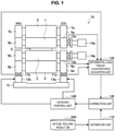
- Figure 1 is an explanatory diagram illustrating a configuration example of a four-high rolling mill and a processing device for performing zigzagging control on a workpiece S according to the present embodiment.
- Figure 1 illustrates a four-high rolling mill
- the present invention is applicable to a rolling mill of four-high or more with a plurality of rolls including at least a pair of work rolls and at least a pair of backup rolls supporting the work rolls.
- a work side is denoted as WS
- a drive side is denoted as DS.
- the work side is an operation side and is opposite to the drive side across the rolling mill.
- a rolling mill 10 illustrated in Figure 1 is a four-high rolling mill that includes a pair of work rolls 1 and 2 and a pair of backup rolls 3 and 4 supporting the work rolls 1 and 2.
- the upper work roll 1 is supported by upper work roll chocks 5a and 5b
- the lower work roll 2 is supported by lower work roll chocks 6a and 6b.
- the upper backup roll 3 is supported by upper backup roll chocks 7a and 7b
- the lower backup roll 4 is supported by lower backup roll chocks 8a and 8b.
- the upper work roll 1 and the upper backup roll 3 form an upper roll assembly
- the lower work roll 2 and the lower backup roll 4 form a lower roll assembly.
- the upper backup roll chocks 7a and 7b, and the lower backup roll chocks 8a and 8b are held by a housing 15.
- the rolling mill 10 illustrated in Figure 1 includes lower load sensors 11a and 11b each of which senses a vertical roll load relating to the lower roll assembly.
- the rolling mill 10 may include, in place of the lower load sensors 11a and 11b, upper load sensors each of which senses a vertical roll load relating to the upper roll assembly or may include the upper load sensors together with the lower load sensors 11a and 11b.
- the lower load sensor 11a senses a vertical roll load (rolling load) on the drive side
- the lower load sensor 11b senses a vertical roll load (rolling load) on the work side.
- leveling devices 13a and 13b that apply perpendicularly upward loads to the lower backup roll chocks 8a and 8b, respectively, are provided.
- the leveling devices 13a and 13b are each constituted by, for example, a hydraulic cylinder and can adjust leveling by moving their hydraulic cylinders in a perpendicular direction.
- thrust counterforce measurement apparatuses 12a and 12b that measure roll-axis-direction thrust counterforces are installed on the work rolls 1 and 2 of the rolling mill 10, respectively.
- the thrust counterforce measurement apparatus 12a is provided between the upper work roll chock 5a on the work side and the work roll shift device 14a
- the thrust counterforce measurement apparatus 12b is provided between the lower work roll chock 6a on the work side and the work roll shift device 14b.
- the work roll shift devices 14a and 14b are driving devices for moving the work rolls 1 and 2 in the roll-axis direction, support the upper work roll chock 5a and the lower work roll chock 6a, respectively, and generate counterforces (roll-axis-direction thrust counterforces) that support the inter-roll thrust force and the material-roll thrust force.
- the roll-axis-direction thrust counterforces measured by the thrust counterforce measurement apparatuses 12a and 12b are output to a differential-load thrust-counterforce acquisition unit 120.
- the rolling mill 10 includes, as illustrated in Figure 1 , an estimation unit 110, the differential-load thrust-counterforce acquisition unit 120, a correction unit 130, and a leveling control unit 140, as a device that performs information processing for performing reduction leveling control by the leveling devices 13a and 13b.
- the processing device having these functional units may be constituted by generic members and circuits or may be constituted by pieces of hardware that are specialized in the functions of the constituent components. Alternatively, the functions of the constituent components of the processing device may be all fulfilled by a CPU or the like.
- a configuration used for the processing device can be altered as appropriate in accordance with a technological standard of a time at which the present embodiment is carried out.
- a computer program for implementing the functions of the processing device can be fabricated and installed in a personal computer or the like.
- a computer-readable recording medium that stores such a computer program can be also provided.
- the computer program may be distributed, for example, over a network without using a recording medium.
- the estimation unit 110 estimates at least any one of an inter-roll thrust force and a material-roll thrust force generated in the rolling mill before a tail portion of the workpiece S is rolled.
- the estimation unit 110 calculates an inter-roll cross angle, a material-roll cross angle, an inter-roll friction coefficient, and a material-roll friction coefficient based on rolling loads, rolling reduction rates, and thrust counterforces acting on a roll other than the backup roll at four levels or more acquired from at least any one of the upper and lower roll assemblies and calculates at least any one of the inter-roll thrust force and the material-roll thrust force.
- actual rolling result data stored in an actual rolling result database 200 may be used.
- the differential-load thrust-counterforce acquisition unit 120 acquires a drive-side rolling load sensed by the lower load sensor 11a and a work-side rolling load sensed by the lower load sensor 11b and calculates a rolling load difference or a rolling load difference ratio as rolling-load-difference information.
- the rolling load difference is a difference between the drive-side rolling load and the work-side rolling load
- the rolling load difference ratio is a ratio of the load difference to a total load (i.e., a sum of the drive-side rolling load and the work-side rolling load) (load difference/total load).
- the rolling load difference ratio enables elimination of a sensing error attributable to a difference in characteristics between right and left load sensors.
- the sensed rolling load difference ratio does not fluctuate if the rolling loads fluctuate due to changes in temperature, sheet width, sheet thickness, and the like. Therefore, by using the rolling load difference ratio, a centerline deviation can be corrected more accurately as compared with a case of using the rolling load difference.
- the correction unit 130 corrects the rolling load difference or the rolling load difference ratio calculated by the differential-load thrust-counterforce acquisition unit 120 based on the measured roll-axis-direction thrust counterforces and the inter-roll thrust force or the material-roll thrust force calculated by the estimation unit 110. This removes a rolling load difference or a rolling load difference ratio attributable to the thrust forces from a rolling load difference or a rolling load difference ratio used in the reduction leveling control.
- the leveling control unit 140 controls the leveling devices 13a and 13b.
- the leveling control unit 140 performs the reduction leveling control using the rolling load difference or the rolling load difference ratio corrected by the correction unit 130.
- the reduction leveling control can be performed by using a well-known method such as reduction leveling control described in Patent Document 1 described above.
- the reduction leveling control is performed with a rolling load difference or a rolling load difference ratio from which a component attributable to the thrust forces serving as disturbance is removed.
- a rolling load difference or a rolling load difference ratio from which a component attributable to the thrust forces serving as disturbance is removed.
- the roll-axis-direction thrust counterforce is measurable.
- the inter-roll thrust force and the material-roll thrust force cannot be measured, and thus it is necessary to acquire at least any one of them through estimation. To do so, it is necessary to acquire the inter-roll cross angle, the material-roll cross angle, the inter-roll friction coefficient, and the material-roll friction coefficient through measurement or estimation.
- Figure 2 is a schematic diagram illustrating forces that act in the rolling mill 10 illustrated in Figure 1 . Although Figure 2 illustrates only forces that act in the lower roll assembly, the description holds true for the upper roll assembly.
- a material-roll friction coefficient ⁇ WM , an inter-roll friction coefficient ⁇ WB , a material-roll cross angle ⁇ WM , and an inter-roll cross angle ⁇ WB are acquired through estimation or measurement. Specifically, 16 cases shown in Table 1 below are possible. Table 1 also shows formulas for determining a material-roll thrust force T WM B , an inter-roll thrust force T WB B , and a thrust counterforce T W B acting on the lower work roll chocks 6a and 6b.
- T WB B T W B + T WM B
- P T df B can be expressed by any one of the following Formulas (4-1) to (4-3).
- the material-roll thrust force T WM B and the inter-roll thrust force T WB B are expressed by, for example, the following Formulas (5a) and (6a) according to Non Patent Document 1.
- calculation of the material-roll thrust force T WM B requires the friction coefficient ⁇ WM between the lower work roll 2 and the workpiece S, the cross angle ⁇ WM between the lower work roll 2 and the workpiece S, the rolling load P, and the rolling reduction rate r. It is also understood that calculation of the inter-roll thrust force T WB B requires the friction coefficient ⁇ WB between the lower work roll 2 and the lower backup roll 4, the inter-roll cross angle ⁇ WB between the lower work roll 2 and the lower backup roll 4, and the rolling load P.
- the thrust counterforce T W B acting on the lower work roll chocks 6a and 6b can be expressed by the following Formula (7a).
- the rolling load P and the rolling reduction rate r can be acquired in a form of their actual values or their setting values.
- the friction coefficient ⁇ WM between the lower work roll 2 and the workpiece S, the friction coefficient ⁇ WB between the lower work roll 2 and the lower backup roll 4, the cross angle ⁇ WM between the lower work roll 2 and the workpiece S, and the inter-roll cross angle ⁇ WB between the lower work roll 2 and the lower backup roll 4 are unknowns.
- the thrust counterforce T W B acting on the lower work roll chocks 6a and 6b is to be measured for combinations of the rolling load P and the rolling reduction rate r at four levels or more.
- the material-roll thrust force T WM B and the inter-roll thrust force T WB B can be acquired from the above Formulas (5a) and (6a) with values of the unknowns determined at the four levels and the rolling load P and the rolling reduction rate r at the fifth and subsequent levels.
- the load difference P T df B attributable to the thrust forces can be calculated from any one of the above Formulas (4-1) to (4-3).
- calculation of the material-roll thrust force T WM B requires the cross angle ⁇ WM between the lower work roll 2 and the workpiece S, the rolling load P, and the rolling reduction rate r. It is also understood that calculation of the inter-roll thrust force T WB B requires the inter-roll cross angle ⁇ WB between the lower work roll 2 and the lower backup roll 4, and the rolling load P.
- the thrust counterforce T W B acting on the lower work roll chocks 6a and 6b can be expressed by the following Formula (7b).
- the rolling load P and the rolling reduction rate r can be acquired in a form of their actual values or their setting values.
- the cross angle ⁇ WM between the lower work roll 2 and the workpiece S, and the inter-roll cross angle ⁇ WB between the lower work roll 2 and the lower backup roll 4 are unknowns.
- the thrust counterforce T W B acting on the lower work roll chocks 6a and 6b is to be measured for combinations of the rolling load P and the rolling reduction rate r at two levels or more.
- the material-roll thrust force T WM B and the inter-roll thrust force T WB B can be acquired from the above Formulas (5b) and (6b) with values of the unknowns determined at the two levels and the rolling load P and the rolling reduction rate r at the third and subsequent levels.
- the load difference P T df B attributable to the thrust forces can be calculated from any one of the above Formulas (4-1) to (4-3).
- calculation of the material-roll thrust force T WM B requires the friction coefficient ⁇ WM between the lower work roll 2 and the workpiece S, the rolling load P, and the rolling reduction rate r. It is also understood that calculation of the inter-roll thrust force T WB B requires the friction coefficient ⁇ WB between the lower work roll 2 and the lower backup roll 4, and the rolling load P.
- the thrust counterforce T W B acting on the lower work roll chocks 6a and 6b can be expressed by the following Formula (7c).
- the rolling load P and the rolling reduction rate r can be acquired in a form of their actual values or their setting values.
- the friction coefficient ⁇ WM between the lower work roll 2 and the workpiece S, and the friction coefficient ⁇ WB between the lower work roll 2 and the lower backup roll 4 are unknowns.
- the thrust counterforce T W B acting on the lower work roll chocks 6a and 6b is to be measured for combinations of the rolling load P and the rolling reduction rate r at two levels or more.
- the material-roll thrust force T WM B and the inter-roll thrust force T WB B can be acquired from the above Formulas (5c) and (6c) with values of the unknowns determined at the two levels and the rolling load P and the rolling reduction rate r at the third and subsequent levels.
- the load difference P T df B attributable to the thrust forces can be calculated from any one of the above Formulas (4-1) to (4-3).
- calculation of the material-roll thrust force T WM B requires the rolling load P and the rolling reduction rate r. It is also understood that calculation of the inter-roll thrust force T WB B requires the rolling load P.
- the rolling load P and the rolling reduction rate r can be acquired in a form of their actual values or their setting values. Since there are no unknowns, the material-roll thrust force T WM B and the inter-roll thrust force T WB B can be acquired from Formulas (5d) and (6d) with the rolling load P and the rolling reduction rate r at a first and subsequent levels.
- the load difference P T df B attributable to the thrust forces can be calculated from any one of the above Formulas (4-1) to (4-3).
- the method for calculating the rolling load difference attributable to the thrust forces in accordance with the four patterns of acquiring the material-roll cross angle, the inter-roll cross angle, the material-roll friction coefficient, and the inter-roll friction coefficient is described.
- the material-roll thrust force T WM B can be determined by any one of the above Formulas (5a) to (5d)
- the inter-roll thrust force T WB B can be determined by any one of the Formulas (6a) to (6d).
- the formula that expresses the thrust counterforce T W B acting on the work roll chocks 6a and 6b differs in each case. Specific formulas are as follows.
- FIG. 3 is a flowchart illustrating an outline of the zigzagging control method for a workpiece according to the present embodiment.
- Figure 4 is a flowchart illustrating an example of the zigzagging control method for a workpiece according to the present embodiment.
- the zigzagging control method for a workpiece according to the present embodiment includes an estimation step (S1 of Figure 3 , S10 of Figure 4 ) that is performed before rolling of a tail portion of the workpiece, and a tail control step (S2 of Figure 3 , S20 to S40 of Figure 4 ) that is performed during the rolling of the tail portion of the workpiece.
- the estimation step at least any one of the inter-roll thrust force and the material-roll thrust force is acquired through estimation (S1 of Figure 3 ).
- the inter-roll thrust force can be estimated based on the inter-roll cross angle and the inter-roll friction coefficient.
- the material-roll thrust force can be estimated based on the material-roll cross angle and the material-roll friction coefficient. As shown in the above Table 1, the inter-roll cross angle, the material-roll cross angle, the inter-roll friction coefficient, and the material-roll friction coefficient are each acquired through measurement or estimation.
- rolling-load-difference information calculated based on work-side and drive-side rolling loads is corrected based on any two of parameters including the roll-axis-direction thrust counterforce, the inter-roll thrust force, and the material-roll thrust force, and perform reduction leveling control (S2 of Figure 3 ).
- the work-side and drive-side rolling loads are measured from at least any one of the upper and lower roll assemblies.
- the rolling-load-difference information is corrected based on any two of the parameters including the roll-axis-direction thrust counterforce, the inter-roll thrust force, and the material-roll thrust force.
- the roll-axis-direction thrust counterforce is a thrust counterforce acting on roll other than the backup roll and is measured from at least any one of the upper and lower roll assemblies from which the work-side and drive-side rolling loads are measured.
- the roll-axis-direction thrust counterforce can be measured concurrently with the measurement of the rolling loads.
- the inter-roll thrust force and the material-roll thrust force can be acquired in step S1. Then, based on any two of the acquired parameters, the rolling-load-difference information is corrected, and based on the corrected rolling-load-difference information, the reduction leveling control is performed on the rolling mill.
- the differential load attributable to the inter-roll thrust force can be determined accurately.
- the two parameters can be selected freely. For example, parameters that can be acquired more accurately may be selected to determine the differential load attributable to the inter-roll thrust force.
- Figure 4 illustrates processing in a case where the roll-axis-direction thrust counterforce, and either the inter-roll thrust force or the material-roll thrust force are selected as the two parameters.
- the roll-axis-direction thrust counterforce acting on a roll other than a backup roll and the work-side and drive-side rolling loads are measured at the same time from the at least any one of the upper and lower roll assemblies (S20).
- the roll-axis-direction thrust counterforce is measured at the measurement of the work-side and drive-side rolling loads.
- rolling-load-difference information calculated based on the measured work-side and drive-side rolling loads is corrected (S30).
- the rolling-load-difference information include a rolling load difference that is a difference between the work-side and drive-side rolling loads, a rolling load difference ratio, and the like.
- reduction leveling control is performed on the rolling mill (S40).
- zigzagging control is performed on a workpiece with the material-roll thrust force or the inter-roll thrust force taken into consideration and with influence of a cross angle (e.g., change over time due to wearing away of a liner) and influence of a friction coefficient (e.g., change over time due to wearing away or surface deterioration of a roll) taken into consideration.
- a cross angle e.g., change over time due to wearing away of a liner
- a friction coefficient e.g., change over time due to wearing away or surface deterioration of a roll
- the zigzagging control method for a workpiece will be specifically described below for the following four cases.
- Figure 5 is a flowchart illustrating the zigzagging control method for a workpiece in the case where ⁇ WM , ⁇ WB , ⁇ WM , and ⁇ WB are all acquired through estimation (Case 1).
- the estimation unit 110 performs estimation processing for acquiring the inter-roll cross angle, the material-roll cross angle, the inter-roll friction coefficient, and the material-roll friction coefficient based on actual rolling results that include rolling loads, rolling reduction rates, and thrust counterforces acting on a roll other than the backup roll at four levels or more (S100).
- the rolling loads and the rolling reduction rates used in step S100 may be either their actual values or their setting values.
- the thrust counterforces are measured values obtained by measurement at each level.
- the actual rolling results at four levels or more used in step S100 are stored in the actual rolling result database 200. From the actual rolling result database 200, the estimation unit 110 acquires four or more actual rolling results that have been acquired from at least any one of the upper and lower roll assemblies.
- the actual rolling results at four levels or more used for the estimation do not have to be data that has been acquired continuously on a time-series basis; it will suffice that the actual rolling results are those of any workpieces that have been rolled before a workpiece of which a tail portion is to pass later.
- the friction coefficients and the cross angles in a stationary rolling state hardly change, the friction coefficients and the cross angles can be acquired with change over time taken into consideration by using actual rolling results acquired for four workpieces rolled recently in the estimation.
- the workpieces rolled recently refer to workpieces that are rolled within a period prior to rolling of the workpiece in question in which the friction coefficient or the cross angle can be assumed not to be changed by a replacement of a roll, wearing away of a roll, or the like.
- the actual rolling results at four levels or more may be values that are acquired from different workpieces or may be actual rolling results at a plurality of levels acquired from the same workpieces. An accuracy of the acquired friction coefficient and cross angle increases with an increase in the number of the levels.
- the estimation unit 110 calculates at least any one of the material-roll thrust force T WM B and the inter-roll thrust force T WB B based on the inter-roll cross angle, the material-roll cross angle, the inter-roll friction coefficient, and the material-roll friction coefficient that are acquired as a result of the estimation in step S100 (S110).
- the material-roll thrust force T WM B can be determined by, for example, the above Formula (5a)
- the inter-roll thrust force T WB B can be determined by, for example, the above Formula (6a).
- the processes up to step S110 are performed before the rolling of the tail portion of the workpiece is started. Steps S100 and S110 correspond to step S1 of the processing illustrated in Figure 3 .
- Steps S120 to S140 correspond to step S2 of the processing illustrated in Figure 3 .
- the roll-axis-direction thrust counterforce acting on a roll other than a backup roll and the work-side and drive-side rolling loads are measured at the same time from the at least any one of the upper and lower roll assemblies (S120). Note that it will suffice to acquire the roll-axis-direction thrust counterforce and the work-side and drive-side rolling loads within a period in which tail control works effectively; they are not necessarily measured strictly at the same time.
- the roll-axis-direction thrust counterforces are measured by the thrust counterforce measurement apparatuses 12a and 12b.
- the drive-side rolling load is measured by the lower load sensor 11a, and the work-side rolling load is measured by the lower load sensor 11b.
- the acquired roll-axis-direction thrust counterforces and work-side and drive-side rolling loads are output to the differential-load thrust-counterforce acquisition unit 120.
- the differential-load thrust-counterforce acquisition unit 120 calculates a load difference or a load difference ratio.
- the correction unit 130 corrects the rolling load difference or the rolling load difference ratio calculated based on the measured work-side and drive-side rolling loads (S130).
- the correction unit 130 calculates the rolling load difference attributable to the thrust forces based on any one of the above Formulas (4-1) to (4-3).
- the rolling load difference is corrected by removing the calculated rolling load difference attributable to the thrust forces from the rolling load difference calculated based on the work-side and drive-side rolling loads measured in step S120.
- the correction applies similarly to a case of the rolling load difference ratio.
- the leveling control unit 140 thereafter performs the reduction leveling control based on the rolling load difference or the rolling load difference ratio corrected by the correction unit 130 (S140).
- the leveling control unit 140 calculates controlled variables of the leveling devices 13a and 13b and drives leveling devices 13a and 13b based on the controlled variables.
- Figure 6 is a flowchart illustrating the zigzagging control method for a workpiece in the case where ⁇ WM and ⁇ WB are acquired through measurement, and ⁇ WM and ⁇ WB are acquired through estimation (Case 6)
- Figure 6 is a flowchart illustrating the zigzagging control method for a workpiece in the case where ⁇ WM and ⁇ WB are acquired through measurement, and ⁇ WM and ⁇ WB are acquired through estimation (Case 6).
- Figure 7 is an explanatory diagram illustrating an example of a method for measuring a friction coefficient.
- Figure 8 is an explanatory diagram illustrating another example of the method for measuring a friction coefficient. Note that, in the following description, processes similar to those in Case 1 illustrated in Figure 5 will not be described in detail.
- the estimation unit 110 performs processing for acquiring the inter-roll cross angle and the material-roll cross angle based on actual rolling results that include rolling loads, rolling reduction rates, and thrust counterforces acting on a roll other than the backup roll at two levels or more (S200).
- the rolling loads and the rolling reduction rates used may be either their actual values or their setting values.
- the thrust counterforces are measured values obtained by measurement at each level.
- the actual rolling results at two levels or more used in step S200 are stored in the actual rolling result database 200. From the actual rolling result database 200, the estimation unit 110 acquires two or more actual rolling results that have been acquired from at least any one of the upper and lower roll assemblies.
- the actual rolling results at two levels or more used for the estimation do not have to be data that has been acquired continuously on a time-series basis; it will suffice that the actual rolling results are those from any workpieces that have been rolled before a workpiece of which a tail portion is to pass later, as in Case 1 described above.
- the cross angles can be acquired with change over time taken into consideration by using actual rolling results acquired for two workpieces rolled recently in the estimation.
- the actual rolling results at two levels or more may be values that are acquired from different workpieces or may be actual rolling results at a plurality of levels acquired from the same workpieces. An accuracy of the acquired cross angle increases with an increase in the number of the levels.
- the material-roll friction coefficient ⁇ WM can be acquired based on, for example, a technique described in JP4-284909A .
- a technique described in JP4-284909A an exit-side speed V 0 and a roll peripheral speed V R are measured in a roll stand upstream of a hot finish rolling mill in response to an on signal of a load cell from the roll stand, and a forward slip is acquired from a ratio between the exit-side speed V 0 and the roll peripheral speed V R .
- the exit-side speed V 0 can be measured by an exit-side speed indicator 1 6b that is disposed on an exit side of the roll stand. Then, from the forward slip based on the measured values and an actual value of a rolling load p, a deformation resistance of a workpiece S and a friction coefficient ⁇ WM between a rolling roll and the workpiece are calculated.
- inter-roll friction coefficient ⁇ WB depends on surface roughnesses of objects.
- relationships between inter-roll friction coefficients ⁇ WB and surface roughnesses of the work rolls 1 and 2 and the backup rolls 3 and 4 are determined in advance before these rolls are built in, and these relationships are acquired in a form of a table.
- the table showing the relationships between the inter-roll friction coefficients ⁇ WB and the surface roughnesses of the work rolls 1 and 2 and the backup rolls 3 and 4 can be acquired by, for example, preparing test specimens that are made of the same starting materials as those of the work rolls 1 and 2 and the backup rolls 3 and 4 and have different surface roughnesses and measuring friction coefficients with a tribology tester or the like.
- the inter-roll friction coefficient ⁇ WB can be estimated.
- Surface roughnesses R W and R B of the work rolls 1 and 2 and the backup rolls 3 and 4 can be measured by using, for example, a roughness gage provided for each roll, such as a work-roll roughness gage 17b illustrated in Figure 8 .
- a sheet roughness gage 17a which can measure a surface roughness R M of a workpiece S
- the material-roll friction coefficient ⁇ WM can be similarly acquired.
- the estimation unit 110 calculates at least any one of the material-roll thrust force T WM B and the inter-roll thrust force T WB B based on the inter-roll cross angle and the material-roll cross angle that are acquired as a result of the estimation in step S200, and the measured inter-roll friction coefficient and material-roll friction coefficient (S210).
- the material-roll thrust force T WM B can be determined by, for example, the above Formula (5b), and the inter-roll thrust force T WB B can be determined by, for example, the above Formula (6b).
- the processes up to step S210 are performed before the rolling of the tail portion of the workpiece is started.
- steps S220 to S240 are performed. Processes of steps S220 to S240 are performed as with steps S120 to S140 illustrated in Figure 5 .
- the roll-axis-direction thrust counterforce acting on a roll other than a backup roll and the work-side and drive-side rolling loads are measured at the same time from the at least any one of the upper and lower roll assemblies (S220). Note that it will suffice to acquire the roll-axis-direction thrust counterforce and the work-side and drive-side rolling loads within a period in which tail control works effectively; they are not necessarily measured strictly at the same time. From the work-side and drive-side rolling loads, the differential-load thrust-counterforce acquisition unit 120 calculates a load difference or a load difference ratio.
- the correction unit 130 corrects the rolling load difference or the rolling load difference ratio calculated based on the measured work-side and drive-side rolling loads (S230). Then, the rolling load difference is corrected by removing the calculated rolling load difference attributable to the thrust forces from the rolling load difference calculated based on the work-side and drive-side rolling loads measured in step S220. The correction applies similarly to a case of the rolling load difference ratio.
- the leveling control unit 140 thereafter performs the reduction leveling control based on the rolling load difference or the rolling load difference ratio corrected by the correction unit 130 (S240).
- the leveling control unit 140 calculates controlled variables of the leveling devices 13a and 13b and drives leveling devices 13a and 13b based on the controlled variables.
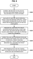
- Figure 9 is a flowchart illustrating the zigzagging control method for a workpiece in the case where ⁇ WM and ⁇ WB are acquired through estimation, and ⁇ WM and ⁇ WB are acquired through measurement (Case 11).
- Figure 10 is an explanatory diagram illustrating an example of a method for measuring a cross angle. Note that, also in the following description, processes similar to those in Case 1 illustrated in Figure 5 will not be described in detail.
- the estimation unit 110 performs processing for acquiring the inter-roll friction coefficient and the material-roll friction coefficient based on actual rolling results that include rolling loads, rolling reduction rates, and thrust counterforces acting on a roll other than the backup roll at two levels or more (S300).
- the rolling loads and the rolling reduction rates used may be either their actual values or their setting values.
- the thrust counterforces are measured values obtained by measurement at each level.
- the actual rolling results at two levels or more used in step S300 are stored in the actual rolling result database 200. From the actual rolling result database 200, the estimation unit 110 acquires two or more actual rolling results that have been acquired from at least any one of the upper and lower roll assemblies.
- the actual rolling results at two levels or more used for the estimation do not have to be data that has been acquired continuously on a time-series basis; it will suffice that the actual rolling results are those from any workpieces that have been rolled before a workpiece of which a tail portion is to pass later, as in Case 1 described above.
- the friction coefficients can be acquired with change over time taken into consideration by using actual rolling results acquired for two workpieces rolled recently in the estimation.
- the actual rolling results at two levels or more may be values that are acquired from different workpieces or may be actual rolling results at a plurality of levels acquired from the same workpieces. An accuracy of the acquired friction coefficient increases with an increase in the number of the levels.
- the inter-roll cross angle ⁇ WB and the material-roll cross angle ⁇ WM are acquired through measurement.
- the cross angle can be determined from a difference between their cylinder positions on the work side (WS) and the drive side (DS).
- WS work side
- DS drive side
- ⁇ W and ⁇ B of the lower work roll 2 and the lower backup roll 4 in the lower roll assembly with reference to Figure 10 .
- the lower work roll 2 is supported by the lower work roll chocks 6a and 6b at its drive side and work side.
- the lower work roll chocks 6a and 6b are pressed against the housing 15 by rolling-direction external-force applying devices 18a and 18b.
- the lower backup roll chocks 8a and 8b are pressed against the housing 15 by rolling-direction external-force applying devices 19a and 19b. Note that the same holds true for the upper roll assembly.
- the estimation unit 110 calculates at least any one of the material-roll thrust force T WM B and the inter-roll thrust force T WB B based on the inter-roll friction coefficient and the material-roll friction coefficient that are acquired as a result of the estimation in step S300, and the measured inter-roll cross angle and material-roll cross angle (S310).
- the material-roll thrust force T WM B can be determined by, for example, the above Formula (5c)
- the inter-roll thrust force T WB B can be determined by, for example, the above Formula (6c).
- the processes up to step S310 are performed before the rolling of the tail portion of the workpiece is started.
- steps S320 to S340 are performed. Processes of steps S320 to S340 are performed as with steps S120 to S140 illustrated in Figure 5 .
- the roll-axis-direction thrust counterforce acting on a roll other than a backup roll and the work-side and drive-side rolling loads are measured at the same time from the at least any one of the upper and lower roll assemblies (S320). Note that it will suffice to acquire the roll-axis-direction thrust counterforce and the work-side and drive-side rolling loads within a period in which tail control works effectively; they are not necessarily measured strictly at the same time. From the work-side and drive-side rolling loads, the differential-load thrust-counterforce acquisition unit 120 calculates a load difference or a load difference ratio.
- the correction unit 130 corrects the rolling load difference or the rolling load difference ratio calculated based on the measured work-side and drive-side rolling loads (S330). Then, the rolling load difference is corrected by removing the calculated rolling load difference attributable to the thrust forces from the rolling load difference calculated based on the work-side and drive-side rolling loads measured in step S320. The correction applies similarly to a case of the rolling load difference ratio.
- the leveling control unit 140 thereafter performs the reduction leveling control based on the rolling load difference or the rolling load difference ratio corrected by the correction unit 130 (S340).
- the leveling control unit 140 calculates controlled variables of the leveling devices 13a and 13b and drives leveling devices 13a and 13b based on the controlled variables.
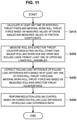
- FIG. 11 is a flowchart illustrating the zigzagging control method for a workpiece in a case where ⁇ WM , ⁇ WB , ⁇ WM , and ⁇ WB are all acquired through measurement (Case 16). Note that, also in the following description, processes similar to those in Case 1 illustrated in Figure 5 will not be described in detail.
- the inter-roll friction coefficient, the material-roll friction coefficient, the inter-roll cross angle, and the material-roll cross angle are acquired through measurement.
- the inter-roll friction coefficient and the material-roll friction coefficient are to be acquired through measurement by the technique illustrated in Figure 7 and Figure 8 .
- the inter-roll cross angle and the material-roll cross angle are to be acquired through measurement by the technique illustrated in Figure 10 .
- the estimation unit 110 calculates at least any one of the material-roll thrust force T WM B and the inter-roll thrust force T WB B based on the inter-roll friction coefficient, the material-roll friction coefficient, the inter-roll cross angle, and the material-roll cross angle that are acquired through measurement (S410).
- the material-roll thrust force T WM B can be determined by, for example, the above Formula (5d)
- the inter-roll thrust force T WB B can be determined by, for example, the above Formula (6d).
- the process of step S410 are performed before the rolling of the tail portion of the workpiece is started.
- steps S420 to S440 are performed. Processes of steps S420 to S440 are performed as with steps S120 to S140 illustrated in Figure 5 .
- the roll-axis-direction thrust counterforce acting on a roll other than a backup roll and the work-side and drive-side rolling loads are measured at the same time from the at least any one of the upper and lower roll assemblies (S420). Note that it will suffice to acquire the roll-axis-direction thrust counterforce and the work-side and drive-side rolling loads within a period in which tail control works effectively; they are not necessarily measured strictly at the same time. From the work-side and drive-side rolling loads, the differential-load thrust-counterforce acquisition unit 120 calculates a load difference or a load difference ratio.
- the correction unit 130 corrects the rolling load difference or the rolling load difference ratio calculated based on the measured work-side and drive-side rolling loads (S430). Then, the rolling load difference is corrected by removing the calculated rolling load difference attributable to the thrust forces from the rolling load difference calculated based on the work-side and drive-side rolling loads measured in step S420. The correction applies similarly to a case of the rolling load difference ratio.
- the leveling control unit 140 thereafter performs the reduction leveling control based on the rolling load difference or the rolling load difference ratio corrected by the correction unit 130 (S440).
- the leveling control unit 140 calculates controlled variables of the leveling devices 13a and 13b and drives leveling devices 13a and 13b based on the controlled variables.
- the zigzagging control method for a workpiece in the case where ⁇ WM , ⁇ WB , ⁇ WM , and ⁇ WB are all acquired through measurement (Case 16) is described. Note that the zigzagging control for a workpiece can be performed in a manner as described above also for the cases other than Cases 1, 6, 11, and 16 shown in Table 1.
- the zigzagging control is performed on a workpiece with the material-roll thrust force or the inter-roll thrust force taken into consideration and with influence of a cross angle (e.g., change over time due to wearing away of a liner) and influence of a friction coefficient (e.g., change over time due to wearing away or surface deterioration of a roll) taken into consideration.
- a cross angle e.g., change over time due to wearing away of a liner
- a friction coefficient e.g., change over time due to wearing away or surface deterioration of a roll
- the cross angles or the friction coefficients are acquired through estimation before a tail portion of the workpiece is rolled, except Case 16 shown in Table 1.
- a learning model for the cross angles and the friction coefficients with higher accuracy can be created.
- the estimation unit 110 calculates, in step S100 illustrated in Figure 5 , an inter-roll cross angle, a material-roll cross angle, an inter-roll friction coefficient, and a material-roll friction coefficient in current rolling based on predicted values of variations of an inter-roll cross angle, a material-roll cross angle, an inter-roll friction coefficient, and a material-roll friction coefficient of each workpiece that are calculated based on a result of past learning, and based on a result of learning an inter-roll cross angle, a material-roll cross angle, an inter-roll friction coefficient, and a material-roll friction coefficient in last rolling.
- cross angles ( ⁇ WM i+1 , ⁇ WB i+1 ) and friction coefficient ( ⁇ WM i+1 , ⁇ WB i+1 ) of an (i+1)th workpiece can be predicted from the following Formulas (12-1) to (12-4).
- the predicted values of the variations are each expressed as a difference in cross angle or friction coefficient between the ith workpiece and the (i-1)th workpiece.
- ( ⁇ WM i - ⁇ WM i-1 ) expresses a predicted value of a variation.
- estimated values which are acquired through estimation out of the inter-roll cross angle, the material-roll cross angle, the inter-roll friction coefficient, and the material-roll friction coefficient, may be corrected in accordance with a difference between an estimated value based on data on constant portions of workpieces rolled in a past and an estimated value based on data on tail portions of the workpieces.
- the material-roll friction coefficient can differ between a constant portion and a tail portion of a workpiece due to influence of scales produced during rolling and the like. For that reason, an estimated value determined based on data on constant portions of workpieces can be an inappropriate value for a tail portion of a workpiece to be actually subjected to the zigzagging control.
- the learning may be performed based on the difference between the estimated value based on the data on constant portions of the workpieces rolled in a past and the estimated value based on the data on the tail portions of the workpieces, and an estimated value for the workpiece in question may be calculated with the difference taken into consideration.
- a tail portion of a workpiece refers to a portion that passes a stand in question since a tail passes a previous stand until the tail passes the stand in question.
- a constant portion of a workpiece refers to a portion of the workpiece excluding a leading portion and a tail portion and having a constant shape.
- a constant portion of a workpiece may be considered to be a portion of the workpiece that passes the stand since a front edge of the workpiece is gripped by a next stand until a tail portion of the workpiece passes a previous stand.
- a constant portion of a workpiece may be considered to be a portion of the workpiece equivalent to a constant portion for a previous stand.
- Example 1 simulated Case 1 shown in Table 1; the thrust forces were determined by estimating the cross angles and the friction coefficients, a rolling load difference acquired from measured values was corrected with a rolling load difference attributable to the thrust forces, and the reduction leveling control was performed.
- Example 2 simulated Case 6 shown in Table 1; the thrust forces were determined by acquiring the cross angles through estimation and acquiring the friction coefficients through measurement, a rolling load difference acquired from measured values was corrected with a rolling load difference attributable to the thrust forces, and the reduction leveling control was performed.
- Example 3 simulated Case 11 shown in Table 1; the thrust forces were determined by acquiring the friction coefficients through estimation and acquiring the cross angles through measurement, a rolling load difference acquired from measured values was corrected with a rolling load difference attributable to the thrust forces, and the reduction leveling control was performed.
- Example 4 simulated Case 16 shown in Table 1; the thrust forces were determined by measuring the cross angles and the friction coefficients, a rolling load difference acquired from measured values was corrected with a rolling load difference attributable to the thrust forces, and the reduction leveling control was performed.
- Example 2 a measurement error was taken into consideration; the measurement error was assumed to be 1%.
- the material-roll friction coefficient ⁇ WM was assumed to be 0.2525, and the inter-roll friction coefficient ⁇ WB was assumed to be 0.101.
- the material-roll cross angle ⁇ WM was assumed to be 0.0303°, and the inter-roll cross angle ⁇ WB was assumed to be 0.0303°.
- the material-roll friction coefficient ⁇ WM was assumed to be 0.2525
- the inter-roll friction coefficient ⁇ WB was assumed to be 0.101
- the material-roll cross angle ⁇ WM was assumed to be 0.0303°
- the inter-roll cross angle ⁇ WB was assumed to be 0.0303°.
- the thrust forces are determined by acquiring only the cross angles, a rolling load difference acquired from measured values is corrected with a rolling load difference attributable to the thrust forces, and the reduction leveling control was performed.
- the thrust forces were determined by acquiring only the friction coefficients, a rolling load difference acquired from measured values was corrected with a rolling load difference attributable to the thrust forces, and the reduction leveling control was performed.
- the cross angles and the friction coefficients were not acquired, a rolling load difference acquired from measured values was corrected with a rolling load difference attributable to the thrust forces, and the reduction leveling control was performed.
- the reduction leveling control was performed with the thrust forces not taken into consideration at all.
- the material-roll friction coefficient ⁇ WM was assumed to be 0.3, and the inter-roll friction coefficient ⁇ WB was assumed to be 0.15.
- the material-roll cross angle ⁇ WM was assumed to be 0.031°, and the inter-roll cross angle ⁇ WB was assumed to be 0.031°.
- the material-roll friction coefficient ⁇ WM was assumed to be 0.3, the inter-roll friction coefficient ⁇ WB was assumed to be 0.15, the material-roll cross angle ⁇ WM was assumed to be 0.031°, and the inter-roll cross angle ⁇ WB was assumed to be 0.031°.
- Example 1 and Comparative examples 1 to 4 were evaluated in terms of centerline deviation. As the centerline deviation, a centerline deviation at a time 3 seconds later from occurrence of the thrust forces was used. Results of the simulations are shown in Table 3.
- Examples 1 to 4 succeeded in decreasing a correction error in a differential load attributable to the thrust forces and most succeeded in reducing centerline deviations, as compared with Comparative examples 1 to 4.
- the present embodiment is described about a zigzagging control method for a workpiece in a four-high rolling mill; however, the present invention is not limited to this example.
- the present invention is also applicable to a six-high rolling mill.
Landscapes
- Engineering & Computer Science (AREA)
- Mechanical Engineering (AREA)
- Control Of Metal Rolling (AREA)
Abstract
Description
- The present invention relates to a zigzagging control method for a workpiece.
- When a workpiece is rolled with a rolling mill, the workpiece may cause what is called zigzagging, in which a width-direction center of the workpiece deviates from a mill center while a tail portion of the workpiece is passing through the rolling mill. If a workpiece zigzags, a tail portion of the workpiece may hit a side guide that is placed downstream of a rolling mill through which the workpiece passes; in this case, buckling can occur, in which the workpiece is rolled with a next rolling mill as the workpiece is buckled. The occurrence of buckling of a workpiece causes an excessively heavy rolling load on the rolling mill, which may result in damage to a roll and, in addition, suspension of operation for repair.
- Hence, techniques have been proposed for preventing zigzagging of a workpiece when a tail portion of the workpiece passes a rolling mill. For example,
Patent Document 1 discloses a differential-load type zigzagging control method in which roll-axis-direction thrust counterforces of all of at least either upper rolls or lower rolls other than backup rolls are measured, and an influence of an inter-roll thrust force on a differential load is taken into consideration.Patent Document 2 discloses a differential-load type zigzagging control method in which a work-roll thrust counterforce and a surface profile of a work roll are measured, and influences of an inter-roll thrust force and a material-roll thrust force on a differential load are taken into consideration.Patent Document 3 discloses a differential-load type zigzagging control method in which a skew angle of a roll is measured, and an influence of an inter-roll thrust force on a differential load is taken into consideration.Patent Document 4 discloses a method for controlling a rolling mill in which, before rolling, a roll gap is opened, and a bending force is applied while rollers are driven to identify an influence of an inter-roll thrust force on a differential load, and reduction leveling control is performed with consideration given to the influence of the inter-roll thrust force on the differential load. -
- Patent Document 1:
JP2000-312911A - Patent Document 2:
JP2005-976A - Patent Document 3:
JP2014-4599A - Patent Document 4:
JP2009-178754A - Non Patent Document 1: Y. Liu et al. "Investigation of
- Here, in the conventional differential-load type zigzagging control, work-side and drive-side rolling loads of at least any one of upper and lower roll assemblies are measured to determine a rolling load difference or a rolling load difference ratio, and reduction leveling control is performed on a rolling mill based on this value. However, it is known that if inter-roll cross (a rotation tilt in a horizontal plane) occurs, an axial force between rolls (inter-roll thrust force) is generated. In addition, if material-roll cross occurs, an axial force between a material and a roll (material-roll thrust force) is similarly generated. The material-roll thrust force is small when compared with the inter-roll thrust force but has a significant influence particularly in a case of a low rolling reduction rate. These inter-roll thrust force and material-roll thrust force are supported by counterforces from roll chocks, which causes an overturning moment to act on a roll due to a perpendicular distance between a support point and a line of action of the force (moment arm). Note that the overturning moment of a roll refers to a moment in a plane perpendicular to a longitudinal direction of rolling. It is considered that a difference in vertical direction load cell measured value between the work side and the drive side (differential load) fluctuates at this time so as to establish the balance with the overturning moment. If a differential load attributable to these thrust forces occurs unintentionally, the differential load serves as a disturbance in the reduction leveling control, which becomes a cause of decreasing accuracy of leveling correction.
- In the techniques described in the
above Patent Documents above Patent Document 2, influence coefficients of an inter-roll thrust force and a material-roll thrust force on a differential load are calculated, and a sum of the influence coefficients is multiplied by a measured thrust counterforce to estimate a differential load attributable to thrust forces, by which reduction leveling control is performed. However, this technique lacks the number of parameters to determine the influence coefficients, and thus an accuracy of the estimation is not satisfactory. For this reason, as with theabove Patent Documents - In the technique described in the
above Patent Document 4, it is necessary before rolling to open a roll gap and apply a bending force while rollers are driven to identify an influence of an inter-roll thrust force on a differential load, and this operation is required to be performed in addition to a regular operation. - The present invention is made in view of the problems described above and has an objective to provide a novel, improved zigzagging control method for a workpiece that enables leveling correction to be performed with an influence of thrust forces on a differential load taken into consideration more accurately.
- In order to solve the problem described above, according to an aspect of the present invention, there is provided a zigzagging control method for a workpiece in a rolling mill of four-high or more, the rolling mill including a plurality of rolls that include at least a pair of work rolls and at least a pair of backup rolls supporting the work rolls, an upper roll assembly including an upper work roll and an upper backup roll, a lower roll assembly including a lower work roll and a lower backup roll, the zigzagging control method including: an estimation step of acquiring at least any one of an inter-roll thrust force estimated based on an inter-roll cross angle and an inter-roll friction coefficient that are acquired through measurement or estimation and a material-roll thrust force estimated based on a material-roll cross angle and a material-roll friction coefficient that are acquired through measurement or estimation, the estimation step being performed before rolling of a tail portion of the workpiece; and a tail control step of measuring work-side and drive-side rolling loads of at least any one of the upper and lower roll assemblies, correcting rolling-load-difference information based on any two of acquired parameters including a roll-axis-direction thrust counterforce at the measurement of the rolling loads, the inter-roll thrust force, and the material-roll thrust force that act on a roll other than the backup roll, the rolling-load-difference information being calculated based on the measured work-side and drive-side rolling loads, and performing reduction leveling control on the rolling mill based on the corrected rolling-load-difference information, the tail control step being performed during the rolling of the tail portion of the workpiece.
- In the tail control step, the rolling-load-difference information may be corrected based on the roll-axis-direction thrust counterforce measured at the measurement of the rolling loads and the inter-roll thrust force or the material-roll thrust force acquired in the estimation step.
- In the estimation step, the inter-roll cross angle, the material-roll cross angle, the inter-roll friction coefficient, and the material-roll friction coefficient may be acquired through estimation based on rolling loads, rolling reduction rates, and thrust counterforces acting on the roll other than the backup roll at four levels or more acquired from at least any one of the upper and lower roll assemblies, and at least any one of the inter-roll thrust force and the material-roll thrust force may be acquired through estimation based on the acquired inter-roll cross angle, material-roll cross angle, inter-roll friction coefficient, and material-roll friction coefficient.
- Alternatively, in the estimation step, the inter-roll friction coefficient and the material-roll friction coefficient may be acquired through measurement, the inter-roll cross angle and the material-roll cross angle may be acquired through estimation based on rolling loads, rolling reduction rates, and thrust counterforces acting on the roll other than the backup roll at two levels or more acquired from at least any one of the upper and lower roll assemblies, and at least any one of the inter-roll thrust force and the material-roll thrust force may be acquired through estimation based on the acquired inter-roll cross angle, material-roll cross angle, inter-roll friction coefficient, and material-roll friction coefficient.
- Alternatively, in the estimation step, the inter-roll cross angle and the material-roll cross angle may be acquired through measurement, the inter-roll friction coefficient and the material-roll friction coefficient may be acquired through estimation based on rolling loads, rolling reduction rates, and thrust counterforces acting on the roll other than the backup roll at two levels or more acquired from at least any one of the upper and lower roll assemblies, and at least any one of the inter-roll thrust force and the material-roll thrust force may be acquired through estimation based on the acquired inter-roll cross angle, material-roll cross angle, inter-roll friction coefficient, and material-roll friction coefficient.
- In the estimation step described above, estimated values, which are acquired through estimation out of the inter-roll cross angle, the material-roll cross angle, the inter-roll friction coefficient, and the material-roll friction coefficient, may be acquired in accordance with predicted values of variations of the estimated values of each workpiece estimated based on a result of past learning and a result of estimating estimated values in last rolling.
- In the estimation step, estimated values, which are acquired through estimation out of the inter-roll cross angle, the material-roll cross angle, the inter-roll friction coefficient, and the material-roll friction coefficient, may be corrected in accordance with a difference between an estimated value based on data on constant portions of workpieces rolled in a past and an estimated value based on data on tail portions of the workpieces.
- In the estimation step, rolling loads, rolling reduction rates, and thrust counterforces acting on a roll other than the backup roll for workpieces rolled recently may be used.
- Alternately, in the estimation step, the inter-roll friction coefficient, the material-roll friction coefficient, the inter-roll cross angle, and the material-roll cross angle may be acquired through measurement, and at least any one of the inter-roll thrust force and the material-roll thrust force may be acquired through estimation based on the acquired inter-roll cross angle, material-roll cross angle, inter-roll friction coefficient, and material-roll friction coefficient.
- As described above, according to the present invention, leveling correction can be performed with an influence of the thrust forces on the differential load taken into consideration more accurately.
-
- [
Figure 1] Figure 1 is an explanatory diagram illustrating a configuration example of a four-high rolling mill and a processing device for performing zigzagging control on a workpiece according to an embodiment of the present invention. - [
Figure 2] Figure 2 is a schematic diagram illustrating forces that act in a rolling mill illustrated inFigure 1 . - [
Figure 3] Figure 3 is a flowchart illustrating an outline of a zigzagging control method for a workpiece according to an embodiment of the present invention. - [
Figure 4] Figure 4 is a flowchart illustrating an example of the zigzagging control method for a workpiece according to the embodiment. - [
Figure 5] Figure 5 is a flowchart illustrating a zigzagging control method for a workpiece in a case where µWM, µWB, φWM, and φWB are all acquired through estimation (Case 1). - [
Figure 6] Figure 6 is a flowchart illustrating a zigzagging control method for a workpiece in a case where µWM and µWB are acquired through measurement, and φWM and φWB are acquired through estimation (Case 6). - [
Figure 7] Figure 7 is an explanatory diagram illustrating an example of a method for measuring a friction coefficient. - [
Figure 8] Figure 8 is an explanatory diagram illustrating another example of the method for measuring a friction coefficient. - [
Figure 9] Figure 9 is a flowchart illustrating a zigzagging control method for a workpiece in a case where µWM and µWB are acquired through estimation, and φWM and φWB are acquired through measurement (Case 11). - [
Figure 10] Figure 10 is an explanatory diagram illustrating an example of a method for measuring a cross angle. - [
Figure 11] Figure 11 is a flowchart illustrating a zigzagging control method for a workpiece in a case where µWM, µWB, φWM, and φWB are all acquired through measurement (Case 16). - A preferred embodiment of the present invention will be described below in detail with reference to the accompanying drawings. In the present specification and drawings, components having substantially the same functions and structures are denoted by the same reference characters, and the repeated description thereof will be omitted.
- First, a schematic configuration of a rolling mill to which a zigzagging control method for a workpiece according to an embodiment of the present invention is applied will be described with reference to
Figure 1. Figure 1 is an explanatory diagram illustrating a configuration example of a four-high rolling mill and a processing device for performing zigzagging control on a workpiece S according to the present embodiment. AlthoughFigure 1 illustrates a four-high rolling mill, the present invention is applicable to a rolling mill of four-high or more with a plurality of rolls including at least a pair of work rolls and at least a pair of backup rolls supporting the work rolls. InFigure 1 , in a roll-axis direction, a work side is denoted as WS, and a drive side is denoted as DS. The work side is an operation side and is opposite to the drive side across the rolling mill. - A rolling
mill 10 illustrated inFigure 1 is a four-high rolling mill that includes a pair of work rolls 1 and 2 and a pair of backup rolls 3 and 4 supporting the work rolls 1 and 2. Theupper work roll 1 is supported by upperwork roll chocks lower work roll 2 is supported by lowerwork roll chocks upper backup roll 3 is supported by upper backup roll chocks 7a and 7b, and thelower backup roll 4 is supported by lower backup roll chocks 8a and 8b. Theupper work roll 1 and theupper backup roll 3 form an upper roll assembly, and thelower work roll 2 and thelower backup roll 4 form a lower roll assembly. The upper backup roll chocks 7a and 7b, and the lower backup roll chocks 8a and 8b are held by ahousing 15. - The rolling
mill 10 illustrated inFigure 1 includeslower load sensors mill 10 may include, in place of thelower load sensors lower load sensors lower load sensor 11a senses a vertical roll load (rolling load) on the drive side, and thelower load sensor 11b senses a vertical roll load (rolling load) on the work side. - Below the
lower load sensors devices leveling devices - In addition, thrust
counterforce measurement apparatuses mill 10, respectively. In the rollingmill 10 illustrated inFigure 1 , the thrustcounterforce measurement apparatus 12a is provided between the upper work roll chock 5a on the work side and the workroll shift device 14a, and the thrustcounterforce measurement apparatus 12b is provided between the lower work roll chock 6a on the work side and the workroll shift device 14b. The workroll shift devices counterforce measurement apparatuses counterforce acquisition unit 120. - The rolling
mill 10 according to the present embodiment includes, as illustrated inFigure 1 , anestimation unit 110, the differential-load thrust-counterforce acquisition unit 120, acorrection unit 130, and a levelingcontrol unit 140, as a device that performs information processing for performing reduction leveling control by theleveling devices - The
estimation unit 110 estimates at least any one of an inter-roll thrust force and a material-roll thrust force generated in the rolling mill before a tail portion of the workpiece S is rolled. Theestimation unit 110 calculates an inter-roll cross angle, a material-roll cross angle, an inter-roll friction coefficient, and a material-roll friction coefficient based on rolling loads, rolling reduction rates, and thrust counterforces acting on a roll other than the backup roll at four levels or more acquired from at least any one of the upper and lower roll assemblies and calculates at least any one of the inter-roll thrust force and the material-roll thrust force. As the rolling loads, the rolling reduction rates, and the thrust counterforces acting on the roll other than the backup roll at four levels or more used by theestimation unit 110, actual rolling result data stored in an actualrolling result database 200 may be used. - The differential-load thrust-
counterforce acquisition unit 120 acquires a drive-side rolling load sensed by thelower load sensor 11a and a work-side rolling load sensed by thelower load sensor 11b and calculates a rolling load difference or a rolling load difference ratio as rolling-load-difference information. The rolling load difference is a difference between the drive-side rolling load and the work-side rolling load, and the rolling load difference ratio is a ratio of the load difference to a total load (i.e., a sum of the drive-side rolling load and the work-side rolling load) (load difference/total load). The rolling load difference ratio enables elimination of a sensing error attributable to a difference in characteristics between right and left load sensors. With the same centerline deviation, the sensed rolling load difference ratio does not fluctuate if the rolling loads fluctuate due to changes in temperature, sheet width, sheet thickness, and the like. Therefore, by using the rolling load difference ratio, a centerline deviation can be corrected more accurately as compared with a case of using the rolling load difference. - The
correction unit 130 corrects the rolling load difference or the rolling load difference ratio calculated by the differential-load thrust-counterforce acquisition unit 120 based on the measured roll-axis-direction thrust counterforces and the inter-roll thrust force or the material-roll thrust force calculated by theestimation unit 110. This removes a rolling load difference or a rolling load difference ratio attributable to the thrust forces from a rolling load difference or a rolling load difference ratio used in the reduction leveling control. - The leveling
control unit 140 controls theleveling devices control unit 140 performs the reduction leveling control using the rolling load difference or the rolling load difference ratio corrected by thecorrection unit 130. The reduction leveling control can be performed by using a well-known method such as reduction leveling control described inPatent Document 1 described above. - In the zigzagging control method for a workpiece according to the present embodiment, the reduction leveling control is performed with a rolling load difference or a rolling load difference ratio from which a component attributable to the thrust forces serving as disturbance is removed. To take the load difference attributable to the thrust forces into consideration for such reduction leveling control, it is necessary to acquire two or more values of the inter-roll thrust force, the material-roll thrust force, and the roll-axis-direction thrust counterforce acting on the work roll through measurement or estimation. Of these, the roll-axis-direction thrust counterforce is measurable. In contrast, the inter-roll thrust force and the material-roll thrust force cannot be measured, and thus it is necessary to acquire at least any one of them through estimation. To do so, it is necessary to acquire the inter-roll cross angle, the material-roll cross angle, the inter-roll friction coefficient, and the material-roll friction coefficient through measurement or estimation.
- Hereinafter, a method for calculating the rolling load difference attributable to the thrust forces in accordance with patterns of acquiring the material-roll cross angle, the inter-roll cross angle, the material-roll friction coefficient, and the inter-roll friction coefficient will be described in detail with reference to
Figure 2. Figure 2 is a schematic diagram illustrating forces that act in the rollingmill 10 illustrated inFigure 1 . AlthoughFigure 2 illustrates only forces that act in the lower roll assembly, the description holds true for the upper roll assembly. - A material-roll friction coefficient µWM, an inter-roll friction coefficient µWB, a material-roll cross angle φWM, and an inter-roll cross angle φWB are acquired through estimation or measurement. Specifically, 16 cases shown in Table 1 below are possible. Table 1 also shows formulas for determining a material-roll thrust force TWM B, an inter-roll thrust force TWB B, and a thrust counterforce TW B acting on the lower
work roll chocks - [Table 1]
Table 1 Case µWM µWB φ WM φ WB TWM B TWB B TW B 1 ● ● ● ● Formula(5a) Formula(6a) Formula(7a) 2 ○ ● ● ● Formula(5b) Formula(6a) Formula(7e) 3 ● ○ ● ● Formula(5a) Formula(6b) Formula(7f) 4 ● ● ○ ● Formula(5c) Formula(6a) Formula(7g) 5 ● ● ● ○ Formula(5a) Formula(6c) Formula(7h) 6 ○ ○ ● ● Formula(5b) Formula(6b) Formula(7b) 7 ○ ● ○ ● Formula(5d) Formula(6a) Formula(7i) 8 ○ ● ● ○ Formula(5b) Formula(6c) Formula(7j) 9 ● ○ ○ ● Formula(5c) Formula(6b) Formula(7k) 10 ● ○ ● ○ Formula(5a) Formula(6d) Formula(7l) 11 ● ● ○ ○ Formula(5c) Formula(6c) Formula(7c) 12 ○ ○ ○ ● Formula(5d) Formula(6b) Formula(7m) 13 ○ ○ ● ○ Formula(5b) Formula(6d) Formula(7n) 14 ○ ● ○ ○ Formula(5d) Formula(6c) Formula(7o) 15 ● ○ ○ ○ Formula(5c) Formula(6d) Formula(7p) 16 ○ ○ ○ ○ Formusla(5d) Formula(6d) Formula(7d) ●:estimation, ○:measurement - The following four cases will be described below.
- (Case 1) µWM, µWB, φWM, and φWB are all acquired through estimation
- (Case 6) µWM and µWB are acquired through measurement, and φWM and φWB are acquired through estimation
- (Case 11) µWM and µWB are acquired through estimation, and φWM and φWB are acquired through measurement
- (Case 16) µWM, µWB, φWM, and φWB are all acquired through measurement
- First, a method for calculating the rolling load difference attributable to the thrust forces in a case where µWM, µWB, φWM, and φWB are all acquired through estimation (Case 1) will be described. In
Figure 2 , equilibrium of forces in the roll-axis direction acting on thelower work roll 2, equilibrium of forces in the roll-axis direction acting on thelower backup roll 4, and equilibrium of moments in the lower roll assembly are expressed by the following Formulas (1) to (3). - [Expression 1]


- Symbols represent the following components.
- TWB B: Thrust force that acts between the
lower work roll 2 and the lower backup roll 4 (inter-roll thrust force) - TWM B: Thrust force that acts between the
lower work roll 2 and the workpiece S (material-roll thrust force) - TW B: Thrust counterforce that acts on the lower
work roll chocks - TB B: Thrust counterforce that acts on the lower backup roll chocks 8a and 8b
- PT df B: Load difference attributable to the thrust forces
- a: span between rolling supports
- hB B: Working point position of a thrust counterforce that acts on the lower backup roll chocks 8a and 8b
- DB: Diameter of the
lower backup roll 4 - Dw: Diameter of the
lower work roll 2 - By removing TB B from the above Formulas (1) to (3), PT df B can be expressed by any one of the following Formulas (4-1) to (4-3).
- [Expression 2]


- This shows that, as described above, at least any one of the material-roll thrust force TWM B and the inter-roll thrust force TWB B needs to be estimated to determine the rolling load difference PT df B attributable to the thrust forces.
- Here, the material-roll thrust force TWM B and the inter-roll thrust force TWB B are expressed by, for example, the following Formulas (5a) and (6a) according to
Non Patent Document 1. - [Expression 3]


- Symbols represent the following components.
- µWM: Friction coefficient between the
lower work roll 2 and the workpiece S - µWB: Friction coefficient between the
lower work roll 2 and thelower backup roll 4 - φWM: Cross angle between the
lower work roll 2 and the workpiece S - φWB: Inter-roll cross angle between the
lower work roll 2 and thelower backup roll 4 - γ = (1-r)/r (r: rolling reduction rate)
- GW: Modulus of rigidity of a work roll
- GB: Modulus of rigidity of a backup roll
- p0: Maximum contact pressure between rolls
- P: Rolling load
- That is, it is understood that calculation of the material-roll thrust force TWM B requires the friction coefficient µWM between the
lower work roll 2 and the workpiece S, the cross angle φWM between thelower work roll 2 and the workpiece S, the rolling load P, and the rolling reduction rate r. It is also understood that calculation of the inter-roll thrust force TWB B requires the friction coefficient µWB between thelower work roll 2 and thelower backup roll 4, the inter-roll cross angle φWB between thelower work roll 2 and thelower backup roll 4, and the rolling load P. - Therefore, with Formula (1), the thrust counterforce TW B acting on the lower
work roll chocks - [Expression 4]

- In Formula (7a), the rolling load P and the rolling reduction rate r can be acquired in a form of their actual values or their setting values. In contrast, the friction coefficient µWM between the
lower work roll 2 and the workpiece S, the friction coefficient µWB between thelower work roll 2 and thelower backup roll 4, the cross angle φWM between thelower work roll 2 and the workpiece S, and the inter-roll cross angle φWB between thelower work roll 2 and thelower backup roll 4 are unknowns. In order to determine the four unknowns, the thrust counterforce TW B acting on the lowerwork roll chocks - By using the material-roll thrust force TWM B and the inter-roll thrust force TWB B acquired in this manner, and the measured roll-axis-direction thrust counterforce, the load difference PT df B attributable to the thrust forces can be calculated from any one of the above Formulas (4-1) to (4-3).
- Next, a method for calculating the rolling load difference attributable to the thrust forces in a case where µWM and µWB are acquired through measurement, and φWM and φWB are acquired through estimation (Case 6) will be described. In this case, the material-roll thrust force TWM B and the inter-roll thrust force TWB B that are expressed by Formulas (5a) and (6a) in
Case 1 are expressed by the following Formulas (5b) and (6b). - [Expression 5]


- That is, it is understood that calculation of the material-roll thrust force TWM B requires the cross angle φWM between the
lower work roll 2 and the workpiece S, the rolling load P, and the rolling reduction rate r. It is also understood that calculation of the inter-roll thrust force TWB B requires the inter-roll cross angle φWB between thelower work roll 2 and thelower backup roll 4, and the rolling load P. - Therefore, with Formula (1), the thrust counterforce TW B acting on the lower
work roll chocks - [Expression 6]

- In Formula (7b), the rolling load P and the rolling reduction rate r can be acquired in a form of their actual values or their setting values. In contrast, the cross angle φWM between the
lower work roll 2 and the workpiece S, and the inter-roll cross angle φWB between thelower work roll 2 and thelower backup roll 4 are unknowns. In order to determine the two unknowns, the thrust counterforce TW B acting on the lowerwork roll chocks - By using the material-roll thrust force TWM B and the inter-roll thrust force TWB B acquired in this manner, and the measured roll-axis-direction thrust counterforce, the load difference PT df B attributable to the thrust forces can be calculated from any one of the above Formulas (4-1) to (4-3).
- Next, a method for calculating the rolling load difference attributable to the thrust forces in a case where µWM and µWB are acquired through estimation, and φWM and φ WB are acquired through measurement (Case 11) will be described. In this case, the material-roll thrust force TWM B and the inter-roll thrust force TWB B that are expressed by Formulas (5a) and (6a) in
Case 1 are expressed by the following Formulas (5c) and (6c). - [Expression 7]


- That is, it is understood that calculation of the material-roll thrust force TWM B requires the friction coefficient µWM between the
lower work roll 2 and the workpiece S, the rolling load P, and the rolling reduction rate r. It is also understood that calculation of the inter-roll thrust force TWB B requires the friction coefficient µWB between thelower work roll 2 and thelower backup roll 4, and the rolling load P. - Therefore, with Formula (1), the thrust counterforce TW B acting on the lower
work roll chocks - [Expression 8]

- In Formula (7c), the rolling load P and the rolling reduction rate r can be acquired in a form of their actual values or their setting values. In contrast, the friction coefficient µWM between the
lower work roll 2 and the workpiece S, and the friction coefficient µWB between thelower work roll 2 and thelower backup roll 4 are unknowns. In order to determine the two unknowns, the thrust counterforce TW B acting on the lowerwork roll chocks - By using the material-roll thrust force TWM B and the inter-roll thrust force TWB B acquired in this manner, and the measured roll-axis-direction thrust counterforce, the load difference PT df B attributable to the thrust forces can be calculated from any one of the above Formulas (4-1) to (4-3).
- Next, a method for calculating the rolling load difference attributable to the thrust forces in a case where µWM, µWB, φWM, and φWB are all acquired through measurement (Case 16) will be described. In this case, the material-roll thrust force TWM B and the inter-roll thrust force TWB B that are expressed by Formulas (5a) and (6a) in
Case 1 are expressed by the following Formulas (5d) and (6d). - [Expression 9]


- That is, it is understood that calculation of the material-roll thrust force TWM B requires the rolling load P and the rolling reduction rate r. It is also understood that calculation of the inter-roll thrust force TWB B requires the rolling load P.
- Therefore, with Formula (1), the thrust counterforce TW B acting on the lower
work roll chocks - [Expression 10]

- In Formula (7d), the rolling load P and the rolling reduction rate r can be acquired in a form of their actual values or their setting values. Since there are no unknowns, the material-roll thrust force TWM B and the inter-roll thrust force TWB B can be acquired from Formulas (5d) and (6d) with the rolling load P and the rolling reduction rate r at a first and subsequent levels.
- By using the material-roll thrust force TWM B and the inter-roll thrust force TWB B acquired in this manner, and the measured roll-axis-direction thrust counterforce, the load difference PT df B attributable to the thrust forces can be calculated from any one of the above Formulas (4-1) to (4-3).
- As above, the method for calculating the rolling load difference attributable to the thrust forces in accordance with the four patterns of acquiring the material-roll cross angle, the inter-roll cross angle, the material-roll friction coefficient, and the inter-roll friction coefficient is described. For the cases other than the above cases, as shown in the above Table 1, the material-roll thrust force TWM B can be determined by any one of the above Formulas (5a) to (5d), and the inter-roll thrust force TWB B can be determined by any one of the Formulas (6a) to (6d). Note that the formula that expresses the thrust counterforce TW B acting on the
work roll chocks - [Expression 11]
- (Case 2)

- (Case 3)

- (Case 4)

- (Case 5)

- (Case 7)

- (Case 8)

- (Case 9)

- (Case 10)

- (Case 12)

- (Case 13)

- (Case 14)

- (Case 15)

- A zigzagging control method for a workpiece according to the present embodiment will be described below with reference to
Figure 3 andFigure 4 .Figure 3 is a flowchart illustrating an outline of the zigzagging control method for a workpiece according to the present embodiment.Figure 4 is a flowchart illustrating an example of the zigzagging control method for a workpiece according to the present embodiment. The zigzagging control method for a workpiece according to the present embodiment includes an estimation step (S1 ofFigure 3 , S10 ofFigure 4 ) that is performed before rolling of a tail portion of the workpiece, and a tail control step (S2 ofFigure 3 , S20 to S40 ofFigure 4 ) that is performed during the rolling of the tail portion of the workpiece. - As illustrated in
Figure 3 , in the estimation step, at least any one of the inter-roll thrust force and the material-roll thrust force is acquired through estimation (S1 ofFigure 3 ). The inter-roll thrust force can be estimated based on the inter-roll cross angle and the inter-roll friction coefficient. The material-roll thrust force can be estimated based on the material-roll cross angle and the material-roll friction coefficient. As shown in the above Table 1, the inter-roll cross angle, the material-roll cross angle, the inter-roll friction coefficient, and the material-roll friction coefficient are each acquired through measurement or estimation. - In the tail control step, rolling-load-difference information calculated based on work-side and drive-side rolling loads is corrected based on any two of parameters including the roll-axis-direction thrust counterforce, the inter-roll thrust force, and the material-roll thrust force, and perform reduction leveling control (S2 of
Figure 3 ). - First, the work-side and drive-side rolling loads are measured from at least any one of the upper and lower roll assemblies. Next, the rolling-load-difference information is corrected based on any two of the parameters including the roll-axis-direction thrust counterforce, the inter-roll thrust force, and the material-roll thrust force. The roll-axis-direction thrust counterforce is a thrust counterforce acting on roll other than the backup roll and is measured from at least any one of the upper and lower roll assemblies from which the work-side and drive-side rolling loads are measured. The roll-axis-direction thrust counterforce can be measured concurrently with the measurement of the rolling loads. The inter-roll thrust force and the material-roll thrust force can be acquired in step S1. Then, based on any two of the acquired parameters, the rolling-load-difference information is corrected, and based on the corrected rolling-load-difference information, the reduction leveling control is performed on the rolling mill.
- As long as the any two of the parameters including the roll-axis-direction thrust counterforce, the inter-roll thrust force, and the material-roll thrust force are acquired, the differential load attributable to the inter-roll thrust force can be determined accurately. The two parameters can be selected freely. For example, parameters that can be acquired more accurately may be selected to determine the differential load attributable to the inter-roll thrust force.
-
Figure 4 illustrates processing in a case where the roll-axis-direction thrust counterforce, and either the inter-roll thrust force or the material-roll thrust force are selected as the two parameters. - In the processing illustrated in
Figure 4 , first, the roll-axis-direction thrust counterforce acting on a roll other than a backup roll and the work-side and drive-side rolling loads are measured at the same time from the at least any one of the upper and lower roll assemblies (S20). The roll-axis-direction thrust counterforce is measured at the measurement of the work-side and drive-side rolling loads. Here, it will suffice to acquire the roll-axis-direction thrust counterforce and the work-side and drive-side rolling loads within a period in which tail control works effectively; they are not necessarily measured strictly at the same time. Next, based on the measured roll-axis-direction thrust counterforce, and the inter-roll thrust force or the material-roll thrust force acquired in step S10, rolling-load-difference information calculated based on the measured work-side and drive-side rolling loads is corrected (S30). Examples of the rolling-load-difference information include a rolling load difference that is a difference between the work-side and drive-side rolling loads, a rolling load difference ratio, and the like. Then, based on the corrected rolling-load-difference information, reduction leveling control is performed on the rolling mill (S40). - In the zigzagging control method for a workpiece according to the present embodiment, zigzagging control is performed on a workpiece with the material-roll thrust force or the inter-roll thrust force taken into consideration and with influence of a cross angle (e.g., change over time due to wearing away of a liner) and influence of a friction coefficient (e.g., change over time due to wearing away or surface deterioration of a roll) taken into consideration. This enables leveling correction to be performed with influence of the thrust forces taken into consideration more accurately, and thus the centerline deviation can be reduced. In addition, the zigzagging control method for a workpiece according to the present embodiment can be implemented simply because there is no need to install measurement equipment on a line.
- The zigzagging control method for a workpiece will be specifically described below for the following four cases.
- (Case 1) µWM, µWB, φWM, and φWB are all acquired through estimation
- (Case 6) µWM and µWB are acquired through measurement, and φWM and φWB are acquired through estimation
- (Case 11) µWM and µWB are acquired through estimation, and φWM and φWB are acquired through measurement
- (Case 16) µWM, µWB, φWM, and φWB are all acquired through measurement
- First, with reference to
Figure 5 , a zigzagging control method for a workpiece in a case where µWM, µWB, φWM, and φWB are all acquired through estimation (Case 1) will be described.Figure 5 is a flowchart illustrating the zigzagging control method for a workpiece in the case where µWM, µWB, φWM, and φWB are all acquired through estimation (Case 1). - As illustrated in
Figure 5 , first, before rolling of a tail portion of the workpiece is started, theestimation unit 110 performs estimation processing for acquiring the inter-roll cross angle, the material-roll cross angle, the inter-roll friction coefficient, and the material-roll friction coefficient based on actual rolling results that include rolling loads, rolling reduction rates, and thrust counterforces acting on a roll other than the backup roll at four levels or more (S100). The rolling loads and the rolling reduction rates used in step S100 may be either their actual values or their setting values. The thrust counterforces are measured values obtained by measurement at each level. The actual rolling results at four levels or more used in step S100 are stored in the actual rollingresult database 200. From the actual rollingresult database 200, theestimation unit 110 acquires four or more actual rolling results that have been acquired from at least any one of the upper and lower roll assemblies. - Here, the actual rolling results at four levels or more used for the estimation do not have to be data that has been acquired continuously on a time-series basis; it will suffice that the actual rolling results are those of any workpieces that have been rolled before a workpiece of which a tail portion is to pass later. On the assumption that, while a workpiece that is continuous on a time-series basis passes, the friction coefficients and the cross angles in a stationary rolling state hardly change, the friction coefficients and the cross angles can be acquired with change over time taken into consideration by using actual rolling results acquired for four workpieces rolled recently in the estimation. Note that the workpieces rolled recently refer to workpieces that are rolled within a period prior to rolling of the workpiece in question in which the friction coefficient or the cross angle can be assumed not to be changed by a replacement of a roll, wearing away of a roll, or the like. In addition, the actual rolling results at four levels or more may be values that are acquired from different workpieces or may be actual rolling results at a plurality of levels acquired from the same workpieces. An accuracy of the acquired friction coefficient and cross angle increases with an increase in the number of the levels.
- The
estimation unit 110 calculates at least any one of the material-roll thrust force TWM B and the inter-roll thrust force TWB B based on the inter-roll cross angle, the material-roll cross angle, the inter-roll friction coefficient, and the material-roll friction coefficient that are acquired as a result of the estimation in step S100 (S110). The material-roll thrust force TWM B can be determined by, for example, the above Formula (5a), and the inter-roll thrust force TWB B can be determined by, for example, the above Formula (6a). The processes up to step S110 are performed before the rolling of the tail portion of the workpiece is started. Steps S100 and S110 correspond to step S1 of the processing illustrated inFigure 3 . - Next, during the rolling of the tail portion of the workpiece, the tail control illustrated as the following steps S120 to S140 is performed. Steps S120 to S140 correspond to step S2 of the processing illustrated in
Figure 3 . - First, the roll-axis-direction thrust counterforce acting on a roll other than a backup roll and the work-side and drive-side rolling loads are measured at the same time from the at least any one of the upper and lower roll assemblies (S120). Note that it will suffice to acquire the roll-axis-direction thrust counterforce and the work-side and drive-side rolling loads within a period in which tail control works effectively; they are not necessarily measured strictly at the same time. The roll-axis-direction thrust counterforces are measured by the thrust
counterforce measurement apparatuses lower load sensor 11a, and the work-side rolling load is measured by thelower load sensor 11b. The acquired roll-axis-direction thrust counterforces and work-side and drive-side rolling loads are output to the differential-load thrust-counterforce acquisition unit 120. From the work-side and drive-side rolling loads, the differential-load thrust-counterforce acquisition unit 120 calculates a load difference or a load difference ratio. - Next, based on the measured roll-axis-direction thrust counterforce, and the inter-roll thrust force or the material-roll thrust force calculated by the
estimation unit 110, thecorrection unit 130 corrects the rolling load difference or the rolling load difference ratio calculated based on the measured work-side and drive-side rolling loads (S130). Thecorrection unit 130 calculates the rolling load difference attributable to the thrust forces based on any one of the above Formulas (4-1) to (4-3). Then, the rolling load difference is corrected by removing the calculated rolling load difference attributable to the thrust forces from the rolling load difference calculated based on the work-side and drive-side rolling loads measured in step S120. The correction applies similarly to a case of the rolling load difference ratio. - The leveling
control unit 140 thereafter performs the reduction leveling control based on the rolling load difference or the rolling load difference ratio corrected by the correction unit 130 (S140). The levelingcontrol unit 140 calculates controlled variables of theleveling devices drives leveling devices - As above, the zigzagging control method for a workpiece in the case where µWM, µWB, φWM, and φWB are all acquired through estimation (Case 1) is described.
- Next, with reference to
Figure 6 to Figure 8 , a zigzagging control method for a workpiece in a case where µWM and µWB are acquired through measurement, and φWM and φ WB are acquired through estimation (Case 6) will be described.Figure 6 is a flowchart illustrating the zigzagging control method for a workpiece in the case where µWM and µWB are acquired through measurement, and φWM and φWB are acquired through estimation (Case 6).Figure 7 is an explanatory diagram illustrating an example of a method for measuring a friction coefficient.Figure 8 is an explanatory diagram illustrating another example of the method for measuring a friction coefficient. Note that, in the following description, processes similar to those inCase 1 illustrated inFigure 5 will not be described in detail. - In the present case, as illustrated in
Figure 6 , first, before rolling of a tail portion of the workpiece is started, theestimation unit 110 performs processing for acquiring the inter-roll cross angle and the material-roll cross angle based on actual rolling results that include rolling loads, rolling reduction rates, and thrust counterforces acting on a roll other than the backup roll at two levels or more (S200). The rolling loads and the rolling reduction rates used may be either their actual values or their setting values. The thrust counterforces are measured values obtained by measurement at each level. The actual rolling results at two levels or more used in step S200 are stored in the actual rollingresult database 200. From the actual rollingresult database 200, theestimation unit 110 acquires two or more actual rolling results that have been acquired from at least any one of the upper and lower roll assemblies. - Here, the actual rolling results at two levels or more used for the estimation do not have to be data that has been acquired continuously on a time-series basis; it will suffice that the actual rolling results are those from any workpieces that have been rolled before a workpiece of which a tail portion is to pass later, as in
Case 1 described above. On the assumption that, while a workpiece that is continuous on a time-series basis passes, the friction coefficients and the cross angles in a stationary rolling state hardly change, the cross angles can be acquired with change over time taken into consideration by using actual rolling results acquired for two workpieces rolled recently in the estimation. In addition, the actual rolling results at two levels or more may be values that are acquired from different workpieces or may be actual rolling results at a plurality of levels acquired from the same workpieces. An accuracy of the acquired cross angle increases with an increase in the number of the levels. - In contrast, the inter-roll friction coefficient and the material-roll friction coefficient are acquired through measurement. The material-roll friction coefficient µWM can be acquired based on, for example, a technique described in
JP4-284909A Figure 7 , an exit-side speed V0 and a roll peripheral speed VR are measured in a roll stand upstream of a hot finish rolling mill in response to an on signal of a load cell from the roll stand, and a forward slip is acquired from a ratio between the exit-side speed V0 and the roll peripheral speed VR. The exit-side speed V0 can be measured by an exit-side speed indicator 1 6b that is disposed on an exit side of the roll stand. Then, from the forward slip based on the measured values and an actual value of a rolling load p, a deformation resistance of a workpiece S and a friction coefficient µWM between a rolling roll and the workpiece are calculated. - It is commonly known that the inter-roll friction coefficient µWB depends on surface roughnesses of objects. Hence, for example, relationships between inter-roll friction coefficients µWB and surface roughnesses of the work rolls 1 and 2 and the backup rolls 3 and 4 are determined in advance before these rolls are built in, and these relationships are acquired in a form of a table. The table showing the relationships between the inter-roll friction coefficients µWB and the surface roughnesses of the work rolls 1 and 2 and the backup rolls 3 and 4 can be acquired by, for example, preparing test specimens that are made of the same starting materials as those of the work rolls 1 and 2 and the backup rolls 3 and 4 and have different surface roughnesses and measuring friction coefficients with a tribology tester or the like.
- Then, after the rolls are built in, by measuring surface roughnesses of the work rolls 1 and 2 and the backup rolls 3 and 4 before rolling is started or another timing, and referring to the table acquired in advance, the inter-roll friction coefficient µWB can be estimated. Surface roughnesses RW and RB of the work rolls 1 and 2 and the backup rolls 3 and 4 can be measured by using, for example, a roughness gage provided for each roll, such as a work-
roll roughness gage 17b illustrated inFigure 8 . By providing asheet roughness gage 17a, which can measure a surface roughness RM of a workpiece S, the material-roll friction coefficient µWM can be similarly acquired. - Returning to the description of
Figure 6 , theestimation unit 110 calculates at least any one of the material-roll thrust force TWM B and the inter-roll thrust force TWB B based on the inter-roll cross angle and the material-roll cross angle that are acquired as a result of the estimation in step S200, and the measured inter-roll friction coefficient and material-roll friction coefficient (S210). The material-roll thrust force TWM B can be determined by, for example, the above Formula (5b), and the inter-roll thrust force TWB B can be determined by, for example, the above Formula (6b). The processes up to step S210 are performed before the rolling of the tail portion of the workpiece is started. - Next, during the rolling of the tail portion of the workpiece, the tail control illustrated as the following steps S220 to S240 is performed. Processes of steps S220 to S240 are performed as with steps S120 to S140 illustrated in
Figure 5 . - That is, first, the roll-axis-direction thrust counterforce acting on a roll other than a backup roll and the work-side and drive-side rolling loads are measured at the same time from the at least any one of the upper and lower roll assemblies (S220). Note that it will suffice to acquire the roll-axis-direction thrust counterforce and the work-side and drive-side rolling loads within a period in which tail control works effectively; they are not necessarily measured strictly at the same time. From the work-side and drive-side rolling loads, the differential-load thrust-
counterforce acquisition unit 120 calculates a load difference or a load difference ratio. - Next, based on the measured roll-axis-direction thrust counterforce, and the inter-roll thrust force or the material-roll thrust force calculated by the
estimation unit 110, thecorrection unit 130 corrects the rolling load difference or the rolling load difference ratio calculated based on the measured work-side and drive-side rolling loads (S230). Then, the rolling load difference is corrected by removing the calculated rolling load difference attributable to the thrust forces from the rolling load difference calculated based on the work-side and drive-side rolling loads measured in step S220. The correction applies similarly to a case of the rolling load difference ratio. - The leveling
control unit 140 thereafter performs the reduction leveling control based on the rolling load difference or the rolling load difference ratio corrected by the correction unit 130 (S240). The levelingcontrol unit 140 calculates controlled variables of theleveling devices drives leveling devices - As above, the zigzagging control method for a workpiece in the case where µWM and µWB are acquired through measurement, and φWM and φWB are acquired through estimation (Case 6) is described.
- Next, with reference to
Figure 9 andFigure 10 , a zigzagging control method for a workpiece in a case where µWM and µWB are acquired through estimation, and φWM and φWB are acquired through measurement (Case 11) will be described.Figure 9 is a flowchart illustrating the zigzagging control method for a workpiece in the case where µWM and µWB are acquired through estimation, and φWM and φWB are acquired through measurement (Case 11).Figure 10 is an explanatory diagram illustrating an example of a method for measuring a cross angle. Note that, also in the following description, processes similar to those inCase 1 illustrated inFigure 5 will not be described in detail. - In the present case, as illustrated in
Figure 9 , first, before rolling of a tail portion of the workpiece is started, theestimation unit 110 performs processing for acquiring the inter-roll friction coefficient and the material-roll friction coefficient based on actual rolling results that include rolling loads, rolling reduction rates, and thrust counterforces acting on a roll other than the backup roll at two levels or more (S300). The rolling loads and the rolling reduction rates used may be either their actual values or their setting values. The thrust counterforces are measured values obtained by measurement at each level. The actual rolling results at two levels or more used in step S300 are stored in the actual rollingresult database 200. From the actual rollingresult database 200, theestimation unit 110 acquires two or more actual rolling results that have been acquired from at least any one of the upper and lower roll assemblies. - Here, the actual rolling results at two levels or more used for the estimation do not have to be data that has been acquired continuously on a time-series basis; it will suffice that the actual rolling results are those from any workpieces that have been rolled before a workpiece of which a tail portion is to pass later, as in
Case 1 described above. On the assumption that, while a workpiece that is continuous on a time-series basis passes, the friction coefficients and the cross angles in a stationary rolling state hardly change, the friction coefficients can be acquired with change over time taken into consideration by using actual rolling results acquired for two workpieces rolled recently in the estimation. In addition, the actual rolling results at two levels or more may be values that are acquired from different workpieces or may be actual rolling results at a plurality of levels acquired from the same workpieces. An accuracy of the acquired friction coefficient increases with an increase in the number of the levels. - In contrast, the inter-roll cross angle φWB and the material-roll cross angle φWM are acquired through measurement. For example, in a case where devices that can apply rolling-direction external forces to between chocks and the housing, the cross angle can be determined from a difference between their cylinder positions on the work side (WS) and the drive side (DS). Here, consider cross angles θW and θB of the
lower work roll 2 and thelower backup roll 4 in the lower roll assembly with reference toFigure 10 . Thelower work roll 2 is supported by the lowerwork roll chocks work roll chocks housing 15 by rolling-direction external-force applying devices housing 15 by rolling-direction external-force applying devices - As illustrated in
Figure 10 , let CW W denote a cylinder position of a work roll (WR) on the work side (WS) and CW D denote a cylinder position of the work roll (WR) on the drive side (DS). Similarly, let CB W denote a cylinder position of a backup roll (BUR) on the work side (WS) and CB D denote a cylinder position of the backup roll (BUR) on the drive side (DS). In addition, let a1 denote an inter-chock distance. At this time, the cross angle θW of thelower work roll 2 and the cross angle θB of thelower backup roll 4 are expressed by the following Formulas (8) and (9). - [Expression 12]


- From the above Formulas (8) and (9), the material-roll cross angle φWM and the inter-roll cross angle φWB are expressed by the following Formulas (10) and (11).
- [Expression 13]


- Returning to the description of
Figure 9 , theestimation unit 110 calculates at least any one of the material-roll thrust force TWM B and the inter-roll thrust force TWB B based on the inter-roll friction coefficient and the material-roll friction coefficient that are acquired as a result of the estimation in step S300, and the measured inter-roll cross angle and material-roll cross angle (S310). The material-roll thrust force TWM B can be determined by, for example, the above Formula (5c), and the inter-roll thrust force TWB B can be determined by, for example, the above Formula (6c). The processes up to step S310 are performed before the rolling of the tail portion of the workpiece is started. - Next, during the rolling of the tail portion of the workpiece, the tail control illustrated as the following steps S320 to S340 is performed. Processes of steps S320 to S340 are performed as with steps S120 to S140 illustrated in
Figure 5 . - That is, first, the roll-axis-direction thrust counterforce acting on a roll other than a backup roll and the work-side and drive-side rolling loads are measured at the same time from the at least any one of the upper and lower roll assemblies (S320). Note that it will suffice to acquire the roll-axis-direction thrust counterforce and the work-side and drive-side rolling loads within a period in which tail control works effectively; they are not necessarily measured strictly at the same time. From the work-side and drive-side rolling loads, the differential-load thrust-
counterforce acquisition unit 120 calculates a load difference or a load difference ratio. - Next, based on the measured roll-axis-direction thrust counterforce, and the inter-roll thrust force or the material-roll thrust force calculated by the
estimation unit 110, thecorrection unit 130 corrects the rolling load difference or the rolling load difference ratio calculated based on the measured work-side and drive-side rolling loads (S330). Then, the rolling load difference is corrected by removing the calculated rolling load difference attributable to the thrust forces from the rolling load difference calculated based on the work-side and drive-side rolling loads measured in step S320. The correction applies similarly to a case of the rolling load difference ratio. - The leveling
control unit 140 thereafter performs the reduction leveling control based on the rolling load difference or the rolling load difference ratio corrected by the correction unit 130 (S340). The levelingcontrol unit 140 calculates controlled variables of theleveling devices drives leveling devices - As above, the zigzagging control method for a workpiece in the case where µWM and µWB are acquired through measurement, and φWM and φWB are acquired through estimation (Case 6) is described.
- Next, with reference to
Figure 11 , a zigzagging control method for a workpiece in a case where µWM, µWB, φWM, and φWB are all acquired through measurement (Case 16) will be described.Figure 11 is a flowchart illustrating the zigzagging control method for a workpiece in a case where µWM, µWB, φWM, and φWB are all acquired through measurement (Case 16). Note that, also in the following description, processes similar to those inCase 1 illustrated inFigure 5 will not be described in detail. - In the present case, the inter-roll friction coefficient, the material-roll friction coefficient, the inter-roll cross angle, and the material-roll cross angle are acquired through measurement. The inter-roll friction coefficient and the material-roll friction coefficient are to be acquired through measurement by the technique illustrated in
Figure 7 and Figure 8 . The inter-roll cross angle and the material-roll cross angle are to be acquired through measurement by the technique illustrated inFigure 10 . - The
estimation unit 110 calculates at least any one of the material-roll thrust force TWM B and the inter-roll thrust force TWB B based on the inter-roll friction coefficient, the material-roll friction coefficient, the inter-roll cross angle, and the material-roll cross angle that are acquired through measurement (S410). The material-roll thrust force TWM B can be determined by, for example, the above Formula (5d), and the inter-roll thrust force TWB B can be determined by, for example, the above Formula (6d). The process of step S410 are performed before the rolling of the tail portion of the workpiece is started. - Next, during the rolling of the tail portion of the workpiece, the tail control illustrated as the following steps S420 to S440 is performed. Processes of steps S420 to S440 are performed as with steps S120 to S140 illustrated in
Figure 5 . - That is, first, the roll-axis-direction thrust counterforce acting on a roll other than a backup roll and the work-side and drive-side rolling loads are measured at the same time from the at least any one of the upper and lower roll assemblies (S420). Note that it will suffice to acquire the roll-axis-direction thrust counterforce and the work-side and drive-side rolling loads within a period in which tail control works effectively; they are not necessarily measured strictly at the same time. From the work-side and drive-side rolling loads, the differential-load thrust-
counterforce acquisition unit 120 calculates a load difference or a load difference ratio. - Next, based on the measured roll-axis-direction thrust counterforce, and the inter-roll thrust force or the material-roll thrust force calculated by the
estimation unit 110, thecorrection unit 130 corrects the rolling load difference or the rolling load difference ratio calculated based on the measured work-side and drive-side rolling loads (S430). Then, the rolling load difference is corrected by removing the calculated rolling load difference attributable to the thrust forces from the rolling load difference calculated based on the work-side and drive-side rolling loads measured in step S420. The correction applies similarly to a case of the rolling load difference ratio. - The leveling
control unit 140 thereafter performs the reduction leveling control based on the rolling load difference or the rolling load difference ratio corrected by the correction unit 130 (S440). The levelingcontrol unit 140 calculates controlled variables of theleveling devices drives leveling devices - As above, the zigzagging control method for a workpiece in the case where µWM, µWB, φWM, and φWB are all acquired through measurement (Case 16) is described. Note that the zigzagging control for a workpiece can be performed in a manner as described above also for the cases other than
Cases - According to the present embodiment, the zigzagging control is performed on a workpiece with the material-roll thrust force or the inter-roll thrust force taken into consideration and with influence of a cross angle (e.g., change over time due to wearing away of a liner) and influence of a friction coefficient (e.g., change over time due to wearing away or surface deterioration of a roll) taken into consideration. This enables leveling correction to be performed with influence of the thrust forces taken into consideration more accurately, and thus the centerline deviation can be reduced. In addition, the zigzagging control method for a workpiece according to the present embodiment can be implemented simply because there is no need to install measurement equipment on a line.
- In the zigzagging control method for a workpiece described above, the cross angles or the friction coefficients are acquired through estimation before a tail portion of the workpiece is rolled, except Case 16 shown in Table 1. Here, by learning behavior of the variations of learned values of the cross angles and the friction coefficients since rolls are changed until the rolls are replaced, a learning model for the cross angles and the friction coefficients with higher accuracy can be created.
- For example, in a case where µWM, µWB, φWM, and φWB are all acquired through estimation as in
Case 1 shown in Table 1, theestimation unit 110 calculates, in step S100 illustrated inFigure 5 , an inter-roll cross angle, a material-roll cross angle, an inter-roll friction coefficient, and a material-roll friction coefficient in current rolling based on predicted values of variations of an inter-roll cross angle, a material-roll cross angle, an inter-roll friction coefficient, and a material-roll friction coefficient of each workpiece that are calculated based on a result of past learning, and based on a result of learning an inter-roll cross angle, a material-roll cross angle, an inter-roll friction coefficient, and a material-roll friction coefficient in last rolling. - For example, as shown in the following Table 2, consider a case where a result of learning cross angles and friction coefficients of a first workpiece up to an ith workpiece has been acquired, and a cross angle and a friction coefficient of an (i+1)th workpiece (workpiece in question) are to be estimated.


- At this time, for example, by using the predicted values of the variations of each workpiece, cross angles (φWM i+1, φWB i+1) and friction coefficient (µWM i+1, µWB i+1) of an (i+1)th workpiece can be predicted from the following Formulas (12-1) to (12-4). The predicted values of the variations are each expressed as a difference in cross angle or friction coefficient between the ith workpiece and the (i-1)th workpiece. For example, in Formula (12-1), (µWM i - µWM i-1) expresses a predicted value of a variation.

- Note that, in the cases other than
Case 1 shown in Table 1, values that are acquired through measurement are to be excluded from values to be updated. For example, in Case 6, where µWM and µWB are acquired through measurement, and φWM and φWB are acquired through estimation, the inter-roll cross angle φWB and the material-roll cross angle φWM are to be updated. InCase 11, where µWM and µWB are acquired through estimation, and φWM and φWB are acquired through measurement, the inter-roll friction coefficient µWB and the material-roll friction coefficient µWM are to be updated. In Case 16, however, this processing is not performed because the inter-roll friction coefficient, the material-roll friction coefficient, the inter-roll cross angle, and the material-roll cross angle are all acquired through measurement. - Learning cross angles and friction coefficients in this manner dispenses with a necessity to learn a cross angle and a friction coefficient of the workpiece in question in real time, which can reduce an on-line computational load. Note that items to be learned are not limited to values that are acquired through estimation. In a case where the reduction in the on-line computational load is an objective of the learning processing for cross angles and friction coefficients, the values to be updated are as described above; however, for example, in a case where consideration is given to measures against a sudden anomaly in the measurement apparatuses, the learning of the behavior of the variations may be performed on items that are acquired through measurement.
- In addition, estimated values, which are acquired through estimation out of the inter-roll cross angle, the material-roll cross angle, the inter-roll friction coefficient, and the material-roll friction coefficient, may be corrected in accordance with a difference between an estimated value based on data on constant portions of workpieces rolled in a past and an estimated value based on data on tail portions of the workpieces. For example, the material-roll friction coefficient can differ between a constant portion and a tail portion of a workpiece due to influence of scales produced during rolling and the like. For that reason, an estimated value determined based on data on constant portions of workpieces can be an inappropriate value for a tail portion of a workpiece to be actually subjected to the zigzagging control. Hence, the learning may be performed based on the difference between the estimated value based on the data on constant portions of the workpieces rolled in a past and the estimated value based on the data on the tail portions of the workpieces, and an estimated value for the workpiece in question may be calculated with the difference taken into consideration.
- Note that, in a case of, for example, a rolling mill including a plurality of roll stands such as a hot finish rolling mill, a tail portion of a workpiece refers to a portion that passes a stand in question since a tail passes a previous stand until the tail passes the stand in question. A constant portion of a workpiece refers to a portion of the workpiece excluding a leading portion and a tail portion and having a constant shape. For example, for a stand other than a final stand, a constant portion of a workpiece may be considered to be a portion of the workpiece that passes the stand since a front edge of the workpiece is gripped by a next stand until a tail portion of the workpiece passes a previous stand. For the final stand, a constant portion of a workpiece may be considered to be a portion of the workpiece equivalent to a constant portion for a previous stand.
- In order to verify the effects of the zigzagging control method for a workpiece according to the present invention, a simulation of reduction leveling control on a workpiece was conducted. Conditions for the simulation were specified as follows. The simulation was conducted under the following conditions specified for a small test rolling mill, with consideration given to a wedge (30 µm) and a lateral difference in deformation resistance (35 kg/mm) as disturbances other than the thrust forces.
-
- Work roll diameter: 295.2 mm
- Backup roll diameter: 714.0 mm
- Rolling load: 400 tonf
- Rolling reduction rate: 30%
- Entrance side sheet thickness: 5 mm
- Sheet width: 400 mm
- Rolling speed: 50 mpm
- Material-roll friction coefficient µWM: 0.25
- Inter-roll friction coefficient µWB: 0.1
- Material-roll cross angle φWM: 0.03°
- Inter-roll cross angle φWB: 0.03°
- As Examples 1 to 4, simulations of rolling a workpiece by the zigzagging control method according to the present invention were conducted. Example 1
simulated Case 1 shown in Table 1; the thrust forces were determined by estimating the cross angles and the friction coefficients, a rolling load difference acquired from measured values was corrected with a rolling load difference attributable to the thrust forces, and the reduction leveling control was performed. Example 2 simulated Case 6 shown in Table 1; the thrust forces were determined by acquiring the cross angles through estimation and acquiring the friction coefficients through measurement, a rolling load difference acquired from measured values was corrected with a rolling load difference attributable to the thrust forces, and the reduction leveling control was performed. Example 3simulated Case 11 shown in Table 1; the thrust forces were determined by acquiring the friction coefficients through estimation and acquiring the cross angles through measurement, a rolling load difference acquired from measured values was corrected with a rolling load difference attributable to the thrust forces, and the reduction leveling control was performed. Example 4 simulated Case 16 shown in Table 1; the thrust forces were determined by measuring the cross angles and the friction coefficients, a rolling load difference acquired from measured values was corrected with a rolling load difference attributable to the thrust forces, and the reduction leveling control was performed. - In Examples 2 to 4, a measurement error was taken into consideration; the measurement error was assumed to be 1%. In Example 2, the material-roll friction coefficient µWM was assumed to be 0.2525, and the inter-roll friction coefficient µWB was assumed to be 0.101. In Example 3, the material-roll cross angle φWM was assumed to be 0.0303°, and the inter-roll cross angle φWB was assumed to be 0.0303°. In Example 4, the material-roll friction coefficient µWM was assumed to be 0.2525, the inter-roll friction coefficient µWB was assumed to be 0.101, the material-roll cross angle φWM was assumed to be 0.0303°, and the inter-roll cross angle φWB was assumed to be 0.0303°.
- In contrast, in Comparative example 1, the thrust forces are determined by acquiring only the cross angles, a rolling load difference acquired from measured values is corrected with a rolling load difference attributable to the thrust forces, and the reduction leveling control was performed. In Comparative example 2, the thrust forces were determined by acquiring only the friction coefficients, a rolling load difference acquired from measured values was corrected with a rolling load difference attributable to the thrust forces, and the reduction leveling control was performed. In Comparative example 3, although the thrust forces were taken into consideration, the cross angles and the friction coefficients were not acquired, a rolling load difference acquired from measured values was corrected with a rolling load difference attributable to the thrust forces, and the reduction leveling control was performed. In Comparative example 4, the reduction leveling control was performed with the thrust forces not taken into consideration at all.
- In Comparative example 1, the material-roll friction coefficient µWM was assumed to be 0.3, and the inter-roll friction coefficient µWB was assumed to be 0.15. In Comparative example 2, the material-roll cross angle φWM was assumed to be 0.031°, and the inter-roll cross angle φWB was assumed to be 0.031°. In Comparative example 3, the material-roll friction coefficient µWM was assumed to be 0.3, the inter-roll friction coefficient µWB was assumed to be 0.15, the material-roll cross angle φWM was assumed to be 0.031°, and the inter-roll cross angle φWB was assumed to be 0.031°.
- Methods of Example 1 and Comparative examples 1 to 4 were evaluated in terms of centerline deviation. As the centerline deviation, a centerline deviation at a
time 3 seconds later from occurrence of the thrust forces was used. Results of the simulations are shown in Table 3. - [Table 3]
Table 3 thrust force consideration thrust force estimation load difference attributable to thrust force (A) [tonf] estimated value of load difference attributable to thrust force (B) [tonf] correction error in differential load attributable to thrust force (A-B) [tonf] centerline deviation [mm] cross angle acquirement friction coefficient acquirement Example 1 presence presence (estimation) presence (estimation) 10.30 10.30 0.00 12.40 Example 2 presence presence (estimation) presence (measurement) 10.30 10.31 0.01 12.56 Example 3 presence presence (measurement) presence (estimation) 10.30 10.40 0.09 13.77 Example 4 presence presence (measurement) presence (measurement) 10.30 10.41 0.11 14.07 Comparative example 1 presence presence absence 10.30 10.63 0.33 17.40 Comparative example 2 presence absence presence 10.30 10.61 0.31 17.10 Comparative example 3 presence absence absence 10.30 10.96 0.66 22.39 Comparative example 4 absence - - 10.30 0.00 10.30 168.27 - As seen from Table 3, Examples 1 to 4 succeeded in decreasing a correction error in a differential load attributable to the thrust forces and most succeeded in reducing centerline deviations, as compared with Comparative examples 1 to 4. This demonstrates that using the zigzagging control method for a workpiece according to the present invention enables the leveling correction to be performed with influence of the thrust forces taken into consideration more accurately, and thus the centerline deviation of the workpiece can be reduced.
- A preferred embodiment of the present invention is described above in detail with reference to the accompanying drawings, but the present invention is not limited to the above examples. It is apparent that a person skilled in the art may conceive various alterations and modifications within technical concepts described in the appended claims, and it should be appreciated that they will naturally come under the technical scope of the present invention.
- For example, the present embodiment is described about a zigzagging control method for a workpiece in a four-high rolling mill; however, the present invention is not limited to this example. For example, the present invention is also applicable to a six-high rolling mill.
-
- 1
- upper work roll
- 2
- lower work roll
- 3
- upper backup roll
- 4
- lower backup roll
- 5a
- upper work roll chock (drive side)
- 5b
- upper work roll chock (work side)
- 6a
- lower work roll chock (drive side)
- 6b
- lower work roll chock (work side)
- 7a
- upper backup roll chock (drive side)
- 7b
- upper backup roll chock (work side)
- 8a
- lower backup roll chock (drive side)
- 8b
- lower backup roll chock (work side)
- 10
- rolling mill
- 11a
- lower load sensor (drive side)
- 11b
- lower load sensor (work side)
- 12a
- thrust counterforce measurement apparatus (drive side)
- 12b
- thrust counterforce measurement apparatus (work side)
- 13a
- leveling device (drive side)
- 13b
- leveling device (work side)
- 14a
- work roll shift device (drive side)
- 14b
- work roll shift device (work side)
- 15
- housing
- 16b
- exit-side speed indicator
- 17a
- sheet roughness gage
- 17b
- work-roll roughness gage
- 18a
- rolling-direction external-force applying device (work-roll drive side)
- 18b
- rolling-direction external-force applying device (work-roll work side)
- 19a
- rolling-direction external-force applying device (backup-roll drive side)
- 19b
- rolling-direction external-force applying device (backup-roll work side)
- 110
- estimation unit
- 120
- differential-load thrust-counterforce acquisition unit
- 130
- correction unit
- 140
- leveling control unit
- 200
- actual rolling result database
Claims (9)
- A zigzagging control method for a workpiece in a rolling mill of four-high or more,the rolling mill including a plurality of rolls that include at least a pair of work rolls and at least a pair of backup rolls supporting the work rolls,an upper roll assembly including an upper work roll and an upper backup roll,a lower roll assembly including a lower work roll and a lower backup roll,the zigzagging control method comprising:an estimation step of acquiring at least any one of an inter-roll thrust force estimated based on an inter-roll cross angle and an inter-roll friction coefficient that are acquired through measurement or estimation and a material-roll thrust force estimated based on a material-roll cross angle and a material-roll friction coefficient that are acquired through measurement or estimation, the estimation step being performed before rolling of a tail portion of the workpiece; anda tail control step of measuring work-side and drive-side rolling loads of at least any one of the upper and lower roll assemblies, correcting rolling-load-difference information based on any two of acquired parameters including a roll-axis-direction thrust counterforce at the measurement of the rolling loads, the inter-roll thrust force, and the material-roll thrust force that act on a roll other than the backup roll, the rolling-load-difference information being calculated based on the measured work-side and drive-side rolling loads, and performing reduction leveling control on the rolling mill based on the corrected rolling-load-difference information, the tail control step being performed during the rolling of the tail portion of the workpiece.
- The zigzagging control method for a workpiece according to claim 1, wherein
in the tail control step, the rolling-load-difference information is corrected based on the roll-axis-direction thrust counterforce measured at the measurement of the rolling loads and the inter-roll thrust force or the material-roll thrust force acquired in the estimation step. - The zigzagging control method for a workpiece according to claim 1 or 2, whereinin the estimation step, the inter-roll cross angle, the material-roll cross angle, the inter-roll friction coefficient, and the material-roll friction coefficient are acquired through estimation based on rolling loads, rolling reduction rates, and thrust counterforces acting on a roll other than the backup roll at four levels or more acquired from at least any one of the upper and lower roll assemblies, andat least one of an inter-roll thrust force and a material-roll thrust force is acquired through estimation based on the acquired inter-roll cross angle, material-roll cross angle, inter-roll friction coefficient, and material-roll friction coefficient.
- The zigzagging control method for a workpiece according to claim 1 or 2, whereinin the estimation step,an inter-roll friction coefficient and a material-roll friction coefficient are acquired through measurement, and an inter-roll cross angle and a material-roll cross angle are acquired through estimation based on rolling loads, rolling reduction rates, and thrust counterforces acting on a roll other than the backup roll at two levels or more acquired from at least any one of the upper and lower roll assemblies, andat least one of an inter-roll thrust force and a material-roll thrust force is acquired through estimation based on the acquired inter-roll cross angle, material-roll cross angle, inter-roll friction coefficient, and material-roll friction coefficient.
- The zigzagging control method for a workpiece according to claim 1 or 2, whereinin the estimation step,an inter-roll cross angle and a material-roll cross angle are acquired through measurement, and an inter-roll friction coefficient and a material-roll friction coefficient are acquired through estimation based on rolling loads, rolling reduction rates, and thrust counterforces acting on a roll other than the backup roll at two levels or more acquired from at least any one of the upper and lower roll assemblies, andat least one of an inter-roll thrust force and a material-roll thrust force is acquired through estimation based on the acquired inter-roll cross angle, material-roll cross angle, inter-roll friction coefficient, and material-roll friction coefficient.
- The zigzagging control method for a workpiece according to any one of claims 1 to 5, wherein
in the estimation step, estimated values, which are acquired through estimation out of the inter-roll cross angle, the material-roll cross angle, the inter-roll friction coefficient, and the material-roll friction coefficient, are acquired in accordance with predicted values of variations of the estimated values of each workpiece estimated based on a result of past learning and a result of estimating estimated values in last rolling. - The zigzagging control method for a workpiece according to any one of claims 1 to 6, wherein
in the estimation step, estimated values, which are acquired through estimation out of the inter-roll cross angle, the material-roll cross angle, the inter-roll friction coefficient, and the material-roll friction coefficient, are corrected in accordance with a difference between an estimated value based on data on constant portions of workpieces rolled in a past and an estimated value based on data on tail portions of the workpieces. - The zigzagging control method for a workpiece according to any one of claims 1 to 7, wherein
in the estimation step, rolling loads, rolling reduction rates, and thrust counterforces acting on a roll other than the backup roll for workpieces rolled recently are used. - The zigzagging control method for a workpiece according to claim 1 or 2, whereinin the estimation step,the inter-roll friction coefficient, the material-roll friction coefficient, the inter-roll cross angle, and the material-roll cross angle are acquired through measurement, andat least any one of an inter-roll thrust force and a material-roll thrust force is acquired through estimation based on the acquired inter-roll cross angle, material-roll cross angle, inter-roll friction coefficient, and material-roll friction coefficient.
Applications Claiming Priority (2)
| Application Number | Priority Date | Filing Date | Title |
|---|---|---|---|
| JP2019080276 | 2019-04-19 | ||
| PCT/JP2020/016194 WO2020213542A1 (en) | 2019-04-19 | 2020-04-10 | Method of controlling meandering of material-to-be-rolled |
Publications (3)
| Publication Number | Publication Date |
|---|---|
| EP3957410A1 true EP3957410A1 (en) | 2022-02-23 |
| EP3957410A4 EP3957410A4 (en) | 2023-05-24 |
| EP3957410B1 EP3957410B1 (en) | 2024-09-18 |
Family
ID=72837445
Family Applications (1)
| Application Number | Title | Priority Date | Filing Date |
|---|---|---|---|
| EP20791939.0A Active EP3957410B1 (en) | 2019-04-19 | 2020-04-10 | Method of controlling meandering of material-to-be-rolled |
Country Status (6)
| Country | Link |
|---|---|
| US (1) | US11850644B2 (en) |
| EP (1) | EP3957410B1 (en) |
| JP (1) | JP7092260B2 (en) |
| CN (1) | CN113710386B (en) |
| MX (1) | MX2021012678A (en) |
| WO (1) | WO2020213542A1 (en) |
Families Citing this family (1)
| Publication number | Priority date | Publication date | Assignee | Title |
|---|---|---|---|---|
| TWI824834B (en) * | 2022-11-22 | 2023-12-01 | 國立高雄科技大學 | Roll forming process inspection method |
Family Cites Families (14)
| Publication number | Priority date | Publication date | Assignee | Title |
|---|---|---|---|---|
| JPH04284909A (en) * | 1991-03-08 | 1992-10-09 | Sumitomo Metal Ind Ltd | Method for controlling hot continuous rolling mill |
| US5666837A (en) * | 1991-03-29 | 1997-09-16 | Hitachi Ltd. | Rolling mill and method of using the same |
| JPH1147814A (en) * | 1997-07-30 | 1999-02-23 | Kawasaki Steel Corp | Meander control method for steel sheet |
| US6401506B1 (en) * | 1998-02-27 | 2002-06-11 | Nippon Steel Corporation | Sheet rolling method and sheet rolling mill |
| JP2000003129A (en) | 1998-04-17 | 2000-01-07 | Digital Vision Laboratories:Kk | Electronic watermark embedment apparatus |
| JP2000280015A (en) * | 1999-03-31 | 2000-10-10 | Kawasaki Steel Corp | Meandering control method and apparatus for hot-rolled thin steel strip |
| JP4227243B2 (en) * | 1999-04-27 | 2009-02-18 | 新日本製鐵株式会社 | Control method for tail end meandering of rolling mill |
| JP3863751B2 (en) | 2000-11-17 | 2006-12-27 | 新日本製鐵株式会社 | Rolling position setting method in sheet rolling |
| JP2004167508A (en) * | 2002-11-18 | 2004-06-17 | Jfe Steel Kk | Meandering control method of metal strip in cold tandem rolling mill |
| JP4214004B2 (en) * | 2003-06-13 | 2009-01-28 | 東芝三菱電機産業システム株式会社 | Rolling meander control method |
| JP4962334B2 (en) | 2008-01-31 | 2012-06-27 | Jfeスチール株式会社 | Rolling mill control method |
| JP6212732B2 (en) | 2012-06-21 | 2017-10-18 | Jfeスチール株式会社 | Meander control method and meander control apparatus |
| JP6020479B2 (en) * | 2014-01-29 | 2016-11-02 | Jfeスチール株式会社 | Cold rolling equipment and cold rolling method |
| CN110382127B (en) * | 2017-03-07 | 2020-10-09 | 日本制铁株式会社 | Intersection angle recognition method, intersection angle recognition device and rolling mill |
-
2020
- 2020-04-10 MX MX2021012678A patent/MX2021012678A/en unknown
- 2020-04-10 JP JP2021514926A patent/JP7092260B2/en active Active
- 2020-04-10 EP EP20791939.0A patent/EP3957410B1/en active Active
- 2020-04-10 CN CN202080030229.3A patent/CN113710386B/en active Active
- 2020-04-10 US US17/440,060 patent/US11850644B2/en active Active
- 2020-04-10 WO PCT/JP2020/016194 patent/WO2020213542A1/en not_active Ceased
Also Published As
| Publication number | Publication date |
|---|---|
| CN113710386B (en) | 2023-03-21 |
| EP3957410A4 (en) | 2023-05-24 |
| EP3957410B1 (en) | 2024-09-18 |
| MX2021012678A (en) | 2021-11-12 |
| JP7092260B2 (en) | 2022-06-28 |
| CN113710386A (en) | 2021-11-26 |
| US20220184679A1 (en) | 2022-06-16 |
| US11850644B2 (en) | 2023-12-26 |
| WO2020213542A1 (en) | 2020-10-22 |
| JPWO2020213542A1 (en) | 2021-11-25 |
Similar Documents
| Publication | Publication Date | Title |
|---|---|---|
| JP4792548B1 (en) | Hot rolling equipment and hot rolling method | |
| US20100269556A1 (en) | Method of rolling a metal strip with adjustment of the lateral position of a strip and suitable rolling mill | |
| EP3957410B1 (en) | Method of controlling meandering of material-to-be-rolled | |
| JP2002126813A (en) | Setting method of rolling leveling in sheet rolling | |
| EP3593916B1 (en) | Cross angle identification method, cross angle identification device, and rolling mill | |
| JP4227243B2 (en) | Control method for tail end meandering of rolling mill | |
| JP3067879B2 (en) | Shape control method in strip rolling | |
| JP3396428B2 (en) | Roll setting method and rolling control method for sheet rolling mill | |
| JP4268582B2 (en) | Plate thickness control method and plate thickness / shape non-interference control method | |
| JP4267609B2 (en) | Rolling method and rolling apparatus for metal sheet | |
| EP3838433B1 (en) | Method for identifying thrust reaction force acting point, and rolling method for rolled material | |
| JP2023033789A (en) | meandering control method and meandering control device | |
| JP2002210512A (en) | Rolling position setting method in sheet rolling | |
| EP3797889A1 (en) | Rolling mill and setting method for rolling mill | |
| JP3300202B2 (en) | Rolling force control method in temper rolling of steel strip | |
| JP3664067B2 (en) | Manufacturing method of hot rolled steel sheet | |
| JP3088881B2 (en) | Method of setting reduction of hot plate rolling mill | |
| JPH05269527A (en) | Flat strip shape control method | |
| JPH10175007A (en) | Method for controlling roll gap in rolling mill | |
| JPH0839123A (en) | Method of preventing narrowing in hot rolling | |
| KR20030054635A (en) | Edger gap setting apparatus at hot strip mill and its method | |
| JPH05146811A (en) | Looperless rolling method for continuous hot finishing mill | |
| JPH0890030A (en) | Roll width control method | |
| JPH0199710A (en) | Method for controlling sheet width of stock to be rolled | |
| JPH10192934A (en) | Thickness control method of sheet material in continuous tandem rolling mill |
Legal Events
| Date | Code | Title | Description |
|---|---|---|---|
| STAA | Information on the status of an ep patent application or granted ep patent |
Free format text: STATUS: THE INTERNATIONAL PUBLICATION HAS BEEN MADE |
|
| PUAI | Public reference made under article 153(3) epc to a published international application that has entered the european phase |
Free format text: ORIGINAL CODE: 0009012 |
|
| STAA | Information on the status of an ep patent application or granted ep patent |
Free format text: STATUS: REQUEST FOR EXAMINATION WAS MADE |
|
| 17P | Request for examination filed |
Effective date: 20211118 |
|
| AK | Designated contracting states |
Kind code of ref document: A1 Designated state(s): AL AT BE BG CH CY CZ DE DK EE ES FI FR GB GR HR HU IE IS IT LI LT LU LV MC MK MT NL NO PL PT RO RS SE SI SK SM TR |
|
| DAV | Request for validation of the european patent (deleted) | ||
| DAX | Request for extension of the european patent (deleted) | ||
| RIN1 | Information on inventor provided before grant (corrected) |
Inventor name: NIKKUNI, DAISUKE Inventor name: ISHII, ATSUSHI Inventor name: YAMAGUCHI, KAZUMA |
|
| A4 | Supplementary search report drawn up and despatched |
Effective date: 20230424 |
|
| RIC1 | Information provided on ipc code assigned before grant |
Ipc: B21B 37/72 20060101ALI20230418BHEP Ipc: B21B 37/68 20060101AFI20230418BHEP |
|
| GRAP | Despatch of communication of intention to grant a patent |
Free format text: ORIGINAL CODE: EPIDOSNIGR1 |
|
| STAA | Information on the status of an ep patent application or granted ep patent |
Free format text: STATUS: GRANT OF PATENT IS INTENDED |
|
| INTG | Intention to grant announced |
Effective date: 20240510 |
|
| GRAS | Grant fee paid |
Free format text: ORIGINAL CODE: EPIDOSNIGR3 |
|
| GRAA | (expected) grant |
Free format text: ORIGINAL CODE: 0009210 |
|
| STAA | Information on the status of an ep patent application or granted ep patent |
Free format text: STATUS: THE PATENT HAS BEEN GRANTED |
|
| AK | Designated contracting states |
Kind code of ref document: B1 Designated state(s): AL AT BE BG CH CY CZ DE DK EE ES FI FR GB GR HR HU IE IS IT LI LT LU LV MC MK MT NL NO PL PT RO RS SE SI SK SM TR |
|
| REG | Reference to a national code |
Ref country code: GB Ref legal event code: FG4D |
|
| REG | Reference to a national code |
Ref country code: CH Ref legal event code: EP |
|
| REG | Reference to a national code |
Ref country code: IE Ref legal event code: FG4D |
|
| REG | Reference to a national code |
Ref country code: DE Ref legal event code: R096 Ref document number: 602020038008 Country of ref document: DE |
|
| REG | Reference to a national code |
Ref country code: LT Ref legal event code: MG9D |
|
| PG25 | Lapsed in a contracting state [announced via postgrant information from national office to epo] |
Ref country code: NO Free format text: LAPSE BECAUSE OF FAILURE TO SUBMIT A TRANSLATION OF THE DESCRIPTION OR TO PAY THE FEE WITHIN THE PRESCRIBED TIME-LIMIT Effective date: 20241218 |
|
| PG25 | Lapsed in a contracting state [announced via postgrant information from national office to epo] |
Ref country code: GR Free format text: LAPSE BECAUSE OF FAILURE TO SUBMIT A TRANSLATION OF THE DESCRIPTION OR TO PAY THE FEE WITHIN THE PRESCRIBED TIME-LIMIT Effective date: 20241219 Ref country code: FI Free format text: LAPSE BECAUSE OF FAILURE TO SUBMIT A TRANSLATION OF THE DESCRIPTION OR TO PAY THE FEE WITHIN THE PRESCRIBED TIME-LIMIT Effective date: 20240918 |
|
| PG25 | Lapsed in a contracting state [announced via postgrant information from national office to epo] |
Ref country code: BG Free format text: LAPSE BECAUSE OF FAILURE TO SUBMIT A TRANSLATION OF THE DESCRIPTION OR TO PAY THE FEE WITHIN THE PRESCRIBED TIME-LIMIT Effective date: 20240918 |
|
| PG25 | Lapsed in a contracting state [announced via postgrant information from national office to epo] |
Ref country code: LV Free format text: LAPSE BECAUSE OF FAILURE TO SUBMIT A TRANSLATION OF THE DESCRIPTION OR TO PAY THE FEE WITHIN THE PRESCRIBED TIME-LIMIT Effective date: 20240918 |
|
| PG25 | Lapsed in a contracting state [announced via postgrant information from national office to epo] |
Ref country code: HR Free format text: LAPSE BECAUSE OF FAILURE TO SUBMIT A TRANSLATION OF THE DESCRIPTION OR TO PAY THE FEE WITHIN THE PRESCRIBED TIME-LIMIT Effective date: 20240918 |
|
| REG | Reference to a national code |
Ref country code: NL Ref legal event code: MP Effective date: 20240918 |
|
| PG25 | Lapsed in a contracting state [announced via postgrant information from national office to epo] |
Ref country code: RS Free format text: LAPSE BECAUSE OF FAILURE TO SUBMIT A TRANSLATION OF THE DESCRIPTION OR TO PAY THE FEE WITHIN THE PRESCRIBED TIME-LIMIT Effective date: 20241218 |
|
| PG25 | Lapsed in a contracting state [announced via postgrant information from national office to epo] |
Ref country code: RS Free format text: LAPSE BECAUSE OF FAILURE TO SUBMIT A TRANSLATION OF THE DESCRIPTION OR TO PAY THE FEE WITHIN THE PRESCRIBED TIME-LIMIT Effective date: 20241218 Ref country code: NO Free format text: LAPSE BECAUSE OF FAILURE TO SUBMIT A TRANSLATION OF THE DESCRIPTION OR TO PAY THE FEE WITHIN THE PRESCRIBED TIME-LIMIT Effective date: 20241218 Ref country code: LV Free format text: LAPSE BECAUSE OF FAILURE TO SUBMIT A TRANSLATION OF THE DESCRIPTION OR TO PAY THE FEE WITHIN THE PRESCRIBED TIME-LIMIT Effective date: 20240918 Ref country code: HR Free format text: LAPSE BECAUSE OF FAILURE TO SUBMIT A TRANSLATION OF THE DESCRIPTION OR TO PAY THE FEE WITHIN THE PRESCRIBED TIME-LIMIT Effective date: 20240918 Ref country code: GR Free format text: LAPSE BECAUSE OF FAILURE TO SUBMIT A TRANSLATION OF THE DESCRIPTION OR TO PAY THE FEE WITHIN THE PRESCRIBED TIME-LIMIT Effective date: 20241219 Ref country code: FI Free format text: LAPSE BECAUSE OF FAILURE TO SUBMIT A TRANSLATION OF THE DESCRIPTION OR TO PAY THE FEE WITHIN THE PRESCRIBED TIME-LIMIT Effective date: 20240918 Ref country code: BG Free format text: LAPSE BECAUSE OF FAILURE TO SUBMIT A TRANSLATION OF THE DESCRIPTION OR TO PAY THE FEE WITHIN THE PRESCRIBED TIME-LIMIT Effective date: 20240918 |
|
| REG | Reference to a national code |
Ref country code: AT Ref legal event code: MK05 Ref document number: 1724249 Country of ref document: AT Kind code of ref document: T Effective date: 20240918 |
|
| PG25 | Lapsed in a contracting state [announced via postgrant information from national office to epo] |
Ref country code: NL Free format text: LAPSE BECAUSE OF FAILURE TO SUBMIT A TRANSLATION OF THE DESCRIPTION OR TO PAY THE FEE WITHIN THE PRESCRIBED TIME-LIMIT Effective date: 20240918 |
|
| PG25 | Lapsed in a contracting state [announced via postgrant information from national office to epo] |
Ref country code: IS Free format text: LAPSE BECAUSE OF FAILURE TO SUBMIT A TRANSLATION OF THE DESCRIPTION OR TO PAY THE FEE WITHIN THE PRESCRIBED TIME-LIMIT Effective date: 20250118 Ref country code: PT Free format text: LAPSE BECAUSE OF FAILURE TO SUBMIT A TRANSLATION OF THE DESCRIPTION OR TO PAY THE FEE WITHIN THE PRESCRIBED TIME-LIMIT Effective date: 20250120 |
|
| PG25 | Lapsed in a contracting state [announced via postgrant information from national office to epo] |
Ref country code: RO Free format text: LAPSE BECAUSE OF FAILURE TO SUBMIT A TRANSLATION OF THE DESCRIPTION OR TO PAY THE FEE WITHIN THE PRESCRIBED TIME-LIMIT Effective date: 20240918 Ref country code: SM Free format text: LAPSE BECAUSE OF FAILURE TO SUBMIT A TRANSLATION OF THE DESCRIPTION OR TO PAY THE FEE WITHIN THE PRESCRIBED TIME-LIMIT Effective date: 20240918 |
|
| PG25 | Lapsed in a contracting state [announced via postgrant information from national office to epo] |
Ref country code: ES Free format text: LAPSE BECAUSE OF FAILURE TO SUBMIT A TRANSLATION OF THE DESCRIPTION OR TO PAY THE FEE WITHIN THE PRESCRIBED TIME-LIMIT Effective date: 20240918 |
|
| PG25 | Lapsed in a contracting state [announced via postgrant information from national office to epo] |
Ref country code: AT Free format text: LAPSE BECAUSE OF FAILURE TO SUBMIT A TRANSLATION OF THE DESCRIPTION OR TO PAY THE FEE WITHIN THE PRESCRIBED TIME-LIMIT Effective date: 20240918 Ref country code: EE Free format text: LAPSE BECAUSE OF FAILURE TO SUBMIT A TRANSLATION OF THE DESCRIPTION OR TO PAY THE FEE WITHIN THE PRESCRIBED TIME-LIMIT Effective date: 20240918 |
|
| PG25 | Lapsed in a contracting state [announced via postgrant information from national office to epo] |
Ref country code: CZ Free format text: LAPSE BECAUSE OF FAILURE TO SUBMIT A TRANSLATION OF THE DESCRIPTION OR TO PAY THE FEE WITHIN THE PRESCRIBED TIME-LIMIT Effective date: 20240918 Ref country code: PL Free format text: LAPSE BECAUSE OF FAILURE TO SUBMIT A TRANSLATION OF THE DESCRIPTION OR TO PAY THE FEE WITHIN THE PRESCRIBED TIME-LIMIT Effective date: 20240918 |
|
| PG25 | Lapsed in a contracting state [announced via postgrant information from national office to epo] |
Ref country code: SK Free format text: LAPSE BECAUSE OF FAILURE TO SUBMIT A TRANSLATION OF THE DESCRIPTION OR TO PAY THE FEE WITHIN THE PRESCRIBED TIME-LIMIT Effective date: 20240918 |
|
| REG | Reference to a national code |
Ref country code: DE Ref legal event code: R097 Ref document number: 602020038008 Country of ref document: DE |
|
| PGFP | Annual fee paid to national office [announced via postgrant information from national office to epo] |
Ref country code: DE Payment date: 20250305 Year of fee payment: 6 |
|
| PG25 | Lapsed in a contracting state [announced via postgrant information from national office to epo] |
Ref country code: DK Free format text: LAPSE BECAUSE OF FAILURE TO SUBMIT A TRANSLATION OF THE DESCRIPTION OR TO PAY THE FEE WITHIN THE PRESCRIBED TIME-LIMIT Effective date: 20240918 |
|
| PLBE | No opposition filed within time limit |
Free format text: ORIGINAL CODE: 0009261 |
|
| STAA | Information on the status of an ep patent application or granted ep patent |
Free format text: STATUS: NO OPPOSITION FILED WITHIN TIME LIMIT |
|
| 26N | No opposition filed |
Effective date: 20250619 |
|
| PG25 | Lapsed in a contracting state [announced via postgrant information from national office to epo] |
Ref country code: SE Free format text: LAPSE BECAUSE OF FAILURE TO SUBMIT A TRANSLATION OF THE DESCRIPTION OR TO PAY THE FEE WITHIN THE PRESCRIBED TIME-LIMIT Effective date: 20240918 |
|
| REG | Reference to a national code |
Ref country code: CH Ref legal event code: H13 Free format text: ST27 STATUS EVENT CODE: U-0-0-H10-H13 (AS PROVIDED BY THE NATIONAL OFFICE) Effective date: 20251125 |
|
| PG25 | Lapsed in a contracting state [announced via postgrant information from national office to epo] |
Ref country code: LU Free format text: LAPSE BECAUSE OF NON-PAYMENT OF DUE FEES Effective date: 20250410 |
|
| PG25 | Lapsed in a contracting state [announced via postgrant information from national office to epo] |
Ref country code: MC Free format text: LAPSE BECAUSE OF FAILURE TO SUBMIT A TRANSLATION OF THE DESCRIPTION OR TO PAY THE FEE WITHIN THE PRESCRIBED TIME-LIMIT Effective date: 20240918 |
|
| REG | Reference to a national code |
Ref country code: BE Ref legal event code: MM Effective date: 20250430 |
|
| PG25 | Lapsed in a contracting state [announced via postgrant information from national office to epo] |
Ref country code: BE Free format text: LAPSE BECAUSE OF NON-PAYMENT OF DUE FEES Effective date: 20250430 |
|
| PG25 | Lapsed in a contracting state [announced via postgrant information from national office to epo] |
Ref country code: CH Free format text: LAPSE BECAUSE OF NON-PAYMENT OF DUE FEES Effective date: 20250430 |
|
| PGFP | Annual fee paid to national office [announced via postgrant information from national office to epo] |
Ref country code: GB Payment date: 20260313 Year of fee payment: 7 |
|
| PG25 | Lapsed in a contracting state [announced via postgrant information from national office to epo] |
Ref country code: IE Free format text: LAPSE BECAUSE OF NON-PAYMENT OF DUE FEES Effective date: 20250410 |
|
| PGFP | Annual fee paid to national office [announced via postgrant information from national office to epo] |
Ref country code: IT Payment date: 20260320 Year of fee payment: 7 |
|
| PGFP | Annual fee paid to national office [announced via postgrant information from national office to epo] |
Ref country code: FR Payment date: 20260309 Year of fee payment: 7 |