EP3954787A1 - Highly efficient molten iron alloy refining method - Google Patents
Highly efficient molten iron alloy refining method Download PDFInfo
- Publication number
- EP3954787A1 EP3954787A1 EP19924226.4A EP19924226A EP3954787A1 EP 3954787 A1 EP3954787 A1 EP 3954787A1 EP 19924226 A EP19924226 A EP 19924226A EP 3954787 A1 EP3954787 A1 EP 3954787A1
- Authority
- EP
- European Patent Office
- Prior art keywords
- slag
- iron alloy
- molten iron
- sub
- furnace
- Prior art date
- Legal status (The legal status is an assumption and is not a legal conclusion. Google has not performed a legal analysis and makes no representation as to the accuracy of the status listed.)
- Granted
Links
Images

Classifications
-
- C—CHEMISTRY; METALLURGY
- C21—METALLURGY OF IRON
- C21C—PROCESSING OF PIG-IRON, e.g. REFINING, MANUFACTURE OF WROUGHT-IRON OR STEEL; TREATMENT IN MOLTEN STATE OF FERROUS ALLOYS
- C21C5/00—Manufacture of carbon-steel, e.g. plain mild steel, medium carbon steel or cast steel or stainless steel
- C21C5/28—Manufacture of steel in the converter
- C21C5/36—Processes yielding slags of special composition
-
- C—CHEMISTRY; METALLURGY
- C21—METALLURGY OF IRON
- C21C—PROCESSING OF PIG-IRON, e.g. REFINING, MANUFACTURE OF WROUGHT-IRON OR STEEL; TREATMENT IN MOLTEN STATE OF FERROUS ALLOYS
- C21C5/00—Manufacture of carbon-steel, e.g. plain mild steel, medium carbon steel or cast steel or stainless steel
- C21C5/28—Manufacture of steel in the converter
- C21C5/30—Regulating or controlling the blowing
- C21C5/32—Blowing from above
-
- C—CHEMISTRY; METALLURGY
- C21—METALLURGY OF IRON
- C21C—PROCESSING OF PIG-IRON, e.g. REFINING, MANUFACTURE OF WROUGHT-IRON OR STEEL; TREATMENT IN MOLTEN STATE OF FERROUS ALLOYS
- C21C5/00—Manufacture of carbon-steel, e.g. plain mild steel, medium carbon steel or cast steel or stainless steel
- C21C5/28—Manufacture of steel in the converter
- C21C5/42—Constructional features of converters
- C21C5/46—Details or accessories
-
- C—CHEMISTRY; METALLURGY
- C21—METALLURGY OF IRON
- C21C—PROCESSING OF PIG-IRON, e.g. REFINING, MANUFACTURE OF WROUGHT-IRON OR STEEL; TREATMENT IN MOLTEN STATE OF FERROUS ALLOYS
- C21C5/00—Manufacture of carbon-steel, e.g. plain mild steel, medium carbon steel or cast steel or stainless steel
- C21C5/52—Manufacture of steel in electric furnaces
- C21C5/5229—Manufacture of steel in electric furnaces in a direct current [DC] electric arc furnace
-
- C—CHEMISTRY; METALLURGY
- C21—METALLURGY OF IRON
- C21C—PROCESSING OF PIG-IRON, e.g. REFINING, MANUFACTURE OF WROUGHT-IRON OR STEEL; TREATMENT IN MOLTEN STATE OF FERROUS ALLOYS
- C21C5/00—Manufacture of carbon-steel, e.g. plain mild steel, medium carbon steel or cast steel or stainless steel
- C21C5/52—Manufacture of steel in electric furnaces
- C21C5/5264—Manufacture of alloyed steels including ferro-alloys
-
- C—CHEMISTRY; METALLURGY
- C21—METALLURGY OF IRON
- C21C—PROCESSING OF PIG-IRON, e.g. REFINING, MANUFACTURE OF WROUGHT-IRON OR STEEL; TREATMENT IN MOLTEN STATE OF FERROUS ALLOYS
- C21C5/00—Manufacture of carbon-steel, e.g. plain mild steel, medium carbon steel or cast steel or stainless steel
- C21C5/52—Manufacture of steel in electric furnaces
- C21C5/54—Processes yielding slags of special composition
-
- F—MECHANICAL ENGINEERING; LIGHTING; HEATING; WEAPONS; BLASTING
- F27—FURNACES; KILNS; OVENS; RETORTS
- F27D—DETAILS OR ACCESSORIES OF FURNACES, KILNS, OVENS OR RETORTS, IN SO FAR AS THEY ARE OF KINDS OCCURRING IN MORE THAN ONE KIND OF FURNACE
- F27D15/00—Handling or treating discharged material; Supports or receiving chambers therefor
-
- C—CHEMISTRY; METALLURGY
- C21—METALLURGY OF IRON
- C21C—PROCESSING OF PIG-IRON, e.g. REFINING, MANUFACTURE OF WROUGHT-IRON OR STEEL; TREATMENT IN MOLTEN STATE OF FERROUS ALLOYS
- C21C2250/00—Specific additives; Means for adding material different from burners or lances
- C21C2250/06—Hollow electrode
-
- C—CHEMISTRY; METALLURGY
- C21—METALLURGY OF IRON
- C21C—PROCESSING OF PIG-IRON, e.g. REFINING, MANUFACTURE OF WROUGHT-IRON OR STEEL; TREATMENT IN MOLTEN STATE OF FERROUS ALLOYS
- C21C2300/00—Process aspects
- C21C2300/08—Particular sequence of the process steps
-
- C—CHEMISTRY; METALLURGY
- C21—METALLURGY OF IRON
- C21C—PROCESSING OF PIG-IRON, e.g. REFINING, MANUFACTURE OF WROUGHT-IRON OR STEEL; TREATMENT IN MOLTEN STATE OF FERROUS ALLOYS
- C21C5/00—Manufacture of carbon-steel, e.g. plain mild steel, medium carbon steel or cast steel or stainless steel
- C21C5/28—Manufacture of steel in the converter
- C21C5/42—Constructional features of converters
- C21C5/46—Details or accessories
- C21C5/48—Bottoms or tuyéres of converters
Definitions
- the present invention relates to a method of refining a molten iron alloy by a converter furnace.
- the present invention particularly relates to a refining method capable of reducing a metallic iron content in slag and reducing variation in the metallic iron content in slag for each charge to improve efficiency of a slag treatment.
- Free CaO is contained in slag (hereinafter, also referred to as "converter furnace slag") generated when molten iron alloy such as molten pig iron (hereinafter, also referred to as “hot metal”) is refined in a converter furnace, the free Cao undergoes a hydration reaction and expands, and volume stability decreases.
- slag also referred to as "converter furnace slag”
- hot metal molten iron alloy
- the free Cao undergoes a hydration reaction and expands, and volume stability decreases.
- a treatment method is related to the slag, generally, iron oxide of about 1 to 40% by mass is contained in the slag, and an external appearance of the slag becomes black.
- the slag is used as an aggregate for concrete or the like, the external appearance thereof is uncomfortable.
- a use of the slag is limited to a low-grade application such as a road ground improvement material and a lower-layer roadbed material, and is difficult to use for an upper-layer roadbed material, a concrete aggregate, a stone raw material, or the like.
- the slag is discharged from the converter furnace into a reaction container, and in the container, a reforming material such as coal ash is added to molten converter furnace slag to perform a reforming treatment to reduce the free CaO, and thus, the slag is used for the upper-layer roadbed material, the concrete aggregate, and the like, which are higher-grade applications.
- metallic iron about several tens of mass% of granular iron is contained in the converter furnace slag in a suspended state. Carbon is present in the suspended granular iron, and when the molten slag is reformed, the carbon of the granular iron reacts with iron oxide in the molten slag or an oxygen gas for stirring, and thus, bubbles of a CO gas are generated (forming) in the molten slag, which causes various adverse effects.
- the granular iron in the slag is a factor of yield loss when focusing on converter furnace blowing, and thus, the lower a granular iron content, the more preferable.
- Patent Document 1 discloses a method in which granular iron in molten slag taken out from a converter furnace is settled in a reaction container and then subjected to a slag reforming treatment.
- a settling time also varies, and thus, it is difficult to perform a stable treatment.
- Non-Patent Document 1 when refining is performed in a converter furnace, an oxygen feeding lance is used as one electrode, a voltage is applied between the one electrode and the other electrode provided on a furnace bottom, and information on a distance between a front end of the lance and a molten metal bath surface, a thickness of a slag layer, or the like is obtained by measuring changes in a current, a voltage, and a resistance value during blowing.
- Patent Document 1 Japanese Unexamined Patent Application, First Publication No. 2006-199984
- Non-Patent Document 1 Current distribution characteristics in converter furnace bath when electric potential is applied to molten steel, C. I. Semuikin, V. F. Polyakov, E. V. Semkina, 2003
- An object of the present invention is to provide a molten iron alloy refining method having high efficiency capable of obtaining slag having a small metallic iron content and a small variation thereof as compared with the related art when refining a molten iron alloy in a converter furnace and then simplifying a treatment for reducing iron in the slag in a reforming treatment of the slag.
- the gist of the present invention is as follows.
- the present invention when refining a molten iron alloy in a converter furnace, it is possible to reduce a granular iron content in slag and variation thereof, and then, it is possible to improve efficiency of a reforming treatment of the slag or a bullion recovery treatment.
- the present inventors have investigated a method for reducing a granular iron content in slag and a variation thereof when refining a molten iron alloy in a converter furnace, and focused on energizing a slag bath and a metal bath.
- the present inventors have found that an amount of granular iron contained in the slag and a variation thereof are reduced when a specific amount of electric charge is applied during the energization.
- % represents “mass%” and a “current” represents a "direct current”.
- an "average of direct current” indicates a magnitude of an average value of the direct currents during a time when the direct current is applied. Strictly speaking, the "average of direct current” is a value obtained by averaging the current values at 10 or greater time points at regular time intervals during a time when the direct current is applied.
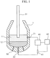
- a first electrode 21 is installed above a molten iron alloy bath (hereinafter, also referred to as an "iron bath") 12 at a position where a frequency of contact with slag 11 increases. Further, a second electrode 22 is disposed in contact with the iron bath 12.
- the first electrode 21 may also serve as a top blowing oxygen feeding lance 31.
- blowing in the converter furnace there are the following methods, that is, 1) a blowing method in the related art for performing desiliconization, dephosphorization, and decarburization, 2) a blowing method in which blowing for the purpose of desiliconization and/or dephosphorization and blowing for the purpose of finish dephosphorization, decarburization, and temperature adjustment are separated from each other, and 3) a blowing method in which desiliconization is performed in a separate process, and then blowing for the purpose of dephosphorization and blowing for the purpose of finish dephosphorization, decarburization, and temperature adjustment are separated from each other.
- the energization is performed during one or both of the blowing for the purpose of desiliconization and/or dephosphorization and the blowing for the purpose of finish dephosphorization, decarburization, and temperature adjustment.
- the blowing of each of 1) to 3) particularly, when applied at an end of the blowing, a larger effect can be obtained.
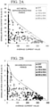
- FIGS. 2A and 2B show results in 3) the blowing method in which desiliconization is performed in a separate process, and then the blowing for the purpose of dephosphorization and the blowing for the purpose of finish dephosphorization, decarburization, and temperature adjustment are separated from each other.
- the first electrode 21 on a side in contact with the slag 11 is disposed on the furnace belly, and the second electrode 22 on a side in contact with the iron bath 12 is disposed on a furnace bottom, and then, with respect to a case where in the case of dephosphorization, a current of 350A or less is supplied between the electrodes for 24 seconds immediately before a stop of the blowing to perform the blowing and in the case of decarburization, a current of 350A or less is supplied between the electrodes for 24 seconds immediately before the stop of the blowing to perform the blowing (ON), and a case where the energization is not performed between the electrodes (OFF), relationships of average current values therebetween, amounts of granular iron, and variations thereof between both cases are shown.
- FIG. 2A shows an effect of the average current value on a metallic iron concentration in the slag after a hot metal dephosphorization treatment in the converter furnace
- FIG. 2B shows an effect on the metallic iron concentration in the slag after a decarburization treatment in the converter furnace.
- the current value increases, an iron content decreases and a variation in the iron content decreases.
- Tables 1 and 2 show an average value (mass%) of the granular iron content (mass%) contained in the slag shown in FIGS. 2A and 2B , a specimen standard deviation, and a relative error.
- the specimen standard deviation is a square root of the variance value obtained by the sum of squares of distances between values of each sample and the average value.
- the relative error is a value obtained by dividing the standard deviation by the average value.
- the slag after a reforming treatment is crushed and the metallic iron is recovered by magnetic sorting.
- Tables 1 and 2 show that the metallic iron content itself is reduced by supplying an electric current to the slag 11, the variation in the metallic iron is reduced, and as a result, the magnetic sorting is stable, and there is a great effect that the metallic iron in the slag can be further reduced.
- I P [A] representing a magnitude of an average of the currents supplied into the slag 11, that is, a magnitude of a direct current during an energization time when the direct current is supplied is controlled so as to satisfy at least one of the following equations (1) and (2), where W s [t] represents an amount of molten steel in the converter furnace, and A s[ m 2 ] represents a furnace internal cross-sectional area at a furnace belly portion.
- a required current flowing into the slag is considered to be related to weight of the molten steel. This is because the weight of the slag inevitably increases as the weight of the molten steel increases, and thus, the amount of granular iron in the slag cannot be reduced within a blowing time unless the current value increases, and as a result, a required energization amount is proportional to the weight of the molten steel.
- the required current flowing into the slag is considered to be related to the furnace internal cross-sectional area of the furnace belly portion of the converter furnace.
- a controlling factor that actually reduces the current density in the slag is the density (current density) of the current flowing into the slag. Since the slag is conductive, a current flows through the entire slag. Therefore, the density of the current flowing into the slag is a value obtained by dividing the current value flowing by the furnace internal cross-sectional area As in the furnace belly portion of the converter furnace, and this value becomes the required current density. That is, the required current density is I p /A s . Assuming that the required current density is a constant value, the required current value is proportional to the furnace internal cross-sectional area of the furnace belly portion.
- the required current flowing into the slag is considered to be proportional to the weight of the molten steel and the cross-sectional area in the furnace. Therefore, in order to reduce the amount of granular iron in the slag and further stabilize the variation, it is preferable to select the smaller of the required current (equation (1)) derived from the weight of the molten steel and the required current (equation (2)) derived from the internal cross-sectional area of the furnace.
- a slag composition before the start of energization has a basicity of 0.5 or greater and an iron oxide concentration of 5% or greater. Since SiO2 in the slag has a strong binding force with each other, SiO 2 hinders conductivity. Meanwhile, CaO has an action of breaking the bond of SiO2, and thus, CaO improves the conductivity. Moreover, iron oxide also improves the conductivity.
- the basicity can be calculated and presumed from a proportion of a charge. Further, the concentration of iron oxide can be calculated from an amount of oxygen feeding, an amount of oxygen contained in an exhaust gas, and an amount of oxygen contained in the molten steel. Since these values are stored as actual values, the values can be presumed before the blowing.
- the composition of the molten iron alloy to be treated is not limited to a specific composition, but it is preferable to treat the molten pig iron having a silicon concentration (Si amount) of 0.25% or less. As the amount of Si increases, the concentration of SiO 2 in the slag increases. Since SiO 2 is a factor that deteriorates conductivity, SiO 2 makes it difficult for current to flow into the slag, and acts in a direction that hinders reduction of the amount of granular iron.
- the amount of Si when the amount of Si is 0.25% or less, the amount of slag required for the blowing is reduced. Since the amount of granular iron generated is determined by the energy input into the furnace (heavy top blowing) and the amount of decarburized, when the amount of slag is small, the concentration of granular iron in the slag is relatively high. When the concentration of granular iron in the slag increases before energization, the reduction effects when energized increase, and thus, the amount of sedimentation of the granular iron increases. Therefore, when the silicon concentration of the molten pig iron is 0.25% or less, a remarkable effect can be obtained.
- the slag density when energized is preferably 1.0 kg/m 3 or less, and more preferably 0.8 kg/m 3 or less. This is because when the density of the slag decreases, a sedimentation rate of the granular iron increases, and the effects of the present invention can be further obtained. Moreover, in the present specification, the slag density means weight of the slag per unit volume when energized in the converter furnace.
- the slag is energized for 10 seconds or longer within on minute before the end of a preset blowing time. That is, it is desirable that a time during which no current is flowing at the end of blowing (after one minute before the stop of oxygen feeding) is set to 50 seconds or less. Furthermore, the shorter an interval between the end of energization and the stop of blowing, the better.
- the reason for this is as follows. 1) When the power is turned off before the end of the blowing, there are concern that the granular iron may be mixed again and the granular iron in the slag may increase. 2) Before the end of the blowing, in most cases, the density of slag is 1.0 kg/m 3 or less, and the slag tends to settle. 3) The amount of granular iron in the slag tends to increase at the end of the blowing when an input auxiliary raw material is sufficiently dissolved and reaction products are sufficiently generated, and when the energization starts in this state, the amount of granular iron tends to decrease.
- I P '[A] representing a magnitude of an average of the direct current during the energization time within one minute immediately before the feeding of the oxygen is stopped is controlled to satisfy at least one of equations (3) and (4), where W s [t] represents the amount of molten steel in the converter furnace, and A s [m 2 ] represents the furnace internal cross-sectional area at the furnace belly portion.
- W s [t] represents the amount of molten steel in the converter furnace
- a s [m 2 ] represents the furnace internal cross-sectional area at the furnace belly portion.
- the effects of the present invention can be obtained by controlling the current so as to satisfy at least one of equations (1) to (4).
- the electrode disposed above the molten iron alloy bath in the converter furnace is a hollow top blowing lance.
- a height of the top blowing lance is controlled based on weight of the residual slag in the furnace, weight of the input auxiliary raw material, weight of the reaction product, the slag density, and a cross-sectional area of the furnace belly portion.
- the slag height H can be calculated by the following equation.
- H m total weight of residual slag in furnace , input auxiliary raw material , and reaction products kg / slag density kg / m 3 ⁇ cross-sectional area of furnace belly portion m 2
- the amount of residual slag in the furnace can be obtained from past operation data, and the input auxiliary raw material and reaction product can be appropriately obtained by using a weighed value and a component value.
- the slag density is not limited to 1.0 kg/m 3 or less, and a value of 2.0 to 3.0 kg/m 3 may be used depending on the composition.
- the slag is considered to expand about 10 times including the generated gas, it is possible that energization can be obtained even when the lance position is about 10 times the slag height obtained by the above equation. Meanwhile, when there is no problem of bullion adhesion to the lance or cooling, it is better to decrease the height of the lance to about 0.1 times the slag height to stabilize the energization.
- a degree of expansion of selection from a range of 0.1 times to 10 times changes depending on blowing conditions and progress of the blowing, and thus, the degree of expansion can be determined theoretically or empirically depending on a time when the effect is desired.
- the lance height By setting the lance height in this way, it is possible to adjust so that the current flows into the slag only when the slag density is about 1.0 kg/m 3 or less, which can promote the reduction of the amount of granular iron.
- a stable operation is possible because the lance does not come into contact with molten steel during operation.
- the converter furnace is a converter furnace having a bottom blowing tuyere. Since the bottom blowing strengthens the agitation of the slag, the reduction of the amount of granular iron in the slag is promoted. In addition, chances of contact between the slag and the molten steel increase, and thus, a transfer of granular iron from the slag to the molten steel is promoted.
- a flow rate of a bottom-blown gas is 0.01 to 0.2 Nm 3 /min/ton in a case of inert gas, and 0.1 to 0.4 Nm 3 /min/ton in a case of blowing of oxygen.
- a first process of performing blowing for the purpose of desiliconization and/or dephosphorization, a second process of discharging a portion of the slag, a third process of performing blowing for the purpose of finish dephosphorization, decarburization, and a temperature adjustment, a fourth process of discharging steel adjusted to the target components and temperature, and a fifth process of discharging a portion of the slag remaining in the furnace are performed in this order.
- the energization is performed for at least 10 seconds or longer during one or both of the oxygen feeding times of the first process and the third process, and when the magnitude of the average of the direct current during the energization time when the direct current is supplied is defined as I P [A], the magnitude of the average of the direct current during the energization time within one minute immediately before the feeding of the oxygen is stopped is defined as Ip'[A], the amount of molten steel in the converter furnace is defined as W s [t], and the furnace internal cross-sectional area at the furnace belly portion is defined as A s [m 2 ], it is effective to control so as to satisfy at least one of the following equations (1) to (4).
- I P ′ ⁇ 0.125 ⁇ W S I P ′ ⁇ 1.5 ⁇
- a S I P ′ ⁇ 0.125 ⁇ W S
- the oxygen feeding time in the first step and the third step is a state in which the density of granular iron in the slag increases, and the amount of granular iron is reduced. Accordingly, the granular iron tends to settle in a molten iron alloy layer, and thus, the metallic iron content in the slag can be easily reduced. In particular, since the amount of granular iron is large in the first step, the variation of the granular iron can be effectively reduced.
- the first electrode 21 of the converter furnace equipment for example, an electrode made of carbon-containing bricks such as MgO-C bricks can be disposed on the furnace belly of the converter furnace.
- the top blowing oxygen feeding lance 31 may be used as shown in FIG. 3 .
- a carbon-containing brick or the like can be used for the second electrode 22.
- the second electrode 22 is provided in the furnace bottom or the furnace belly of the converter furnace equipment 1.
- the first electrode 21 When the first electrode 21 is disposed in the furnace belly, the first electrode 21 is preferably provided 200 mm to 4000 mm above, and more preferably 200 to 400 mm above, based on a static molten metal surface of the iron bath 12 estimated from a volume of the converter furnace.
- a front end thereof When the top blowing oxygen feeding lance 31 is used as the first electrode 21, a front end thereof may be moved up and down, and thus, a position thereof may be moved up and down by the current flowing between the electrodes so that the magnitude of the flowing current can be controlled.
- the power supply device 40 may include a mechanism that cuts off the supply of the current when a resistance value between the first electrode 21 and the second electrode 22 is equal to or greater than a preset current value or greater for a preset time after the start of the blowing.
- the current value is obtained by inputting a signal from the current detection unit 41 to the control device 42. Then, when the obtained current value is equal to or greater than the preset current value within the preset time after the start of the blowing, the output of the power supply device 40 is stopped and the current supply is cut off.
- the power supply device 40 has a function of controlling the current so as not to flow a certain amount or greater.
- the carbon concentration at the refining end point of the dephosphorization treatment is 2.5% by mass or greater. This is because, in most cases, since the refining in the region is performed with a relatively low basicity and the treatment is completed at a low temperature, a viscosity of the slag before energization is high and the amount of granular iron contained in the slag is large, and thus, when the energization is performed, the amount of granular iron can be easily reduced.
- a bottom blowing tuyere 50 made of porous bricks is provided on the furnace bottom and the iron bath 12 is agitated by blowing gas into the iron bath 12 from the furnace bottom during the refining.
- the number of bottom blowing tuyeres 50 may be one, but it is preferable to provide a plurality of bottom blowing tuyeres 50.
- FIG. 1 shows an example in which the bottom blowing tuyeres 50 are provided at two locations.
- the gas flowing from the tuyere is not particularly limited, and any single gas such as oxygen, carbon dioxide, nitrogen, Ar, LPG, or a mixed gas of two or more types can be selected, and a pipe itself can be a single tube, a multiple tube, a collecting pipe, or the like.
- the electrode 22 can also be used as the tuyere. However, in that case, it is necessary to properly insulate of conductive paths of the tuyere and pipe to eliminate the possibility of a large current flowing through an iron shell of a furnace body or a trunnion shaft.
- a furnace inner diameter of a furnace belly portion of a converter furnace was 6 m. That is, a value of 0.125 ⁇ W s is 37.5, and a value of 1.5 ⁇ A s is 42.4.
- MgO-C electrodes were installed on the furnace belly and the furnace bottom, a conductor connecting mechanism was provided on a furnace body side and an operating floor side so that the electrodes could be connected at a furnace hanging position, and a power supply capable of controlling so that a current of 500A or greater does not flow to an operating floor was installed.
- the electrode of the furnace belly was set 250 mm above the static molten metal surface when 300 tons of the main raw material was inserted. After the start of the blowing, energization started and the current began to increase at a timing when it could be presumed from an acoustic state in the furnace that slag in a molten state was generated. After that, energization was performed until the end of the blowing.
- the energization timing was changed and blowing was performed based on the above experimental conditions.
- the blowing was not interrupted even once during the process, and the steel was discharged under the control of a predetermined composition and temperature, and the steel was discharged.
- the oxygen feeding time was set to 20 minutes in total.
- the slag was received in a slag pan, discharged into a yard and cooled, and then fist-sized lumps were randomly collected from 10 locations and analyzed to obtain an average value of the metallic iron content.
- the blowing was performed by 5 charges, the average value of the amounts of granular iron in the slag at that time was calculated, and the standard deviation of 5 charges was calculated.
- the granular iron contained in the slag can be coarsened and dissolved in the metal bath, the slag having a reduced metallic iron content compared with the related art can be stably obtained, and thus, efficiency in the reforming treatment of the slag can be improved.
Landscapes
- Engineering & Computer Science (AREA)
- Chemical & Material Sciences (AREA)
- Manufacturing & Machinery (AREA)
- Materials Engineering (AREA)
- Metallurgy (AREA)
- Organic Chemistry (AREA)
- Mechanical Engineering (AREA)
- General Engineering & Computer Science (AREA)
- Carbon Steel Or Casting Steel Manufacturing (AREA)
Abstract
Description
- The present invention relates to a method of refining a molten iron alloy by a converter furnace. The present invention particularly relates to a refining method capable of reducing a metallic iron content in slag and reducing variation in the metallic iron content in slag for each charge to improve efficiency of a slag treatment.
- Free CaO is contained in slag (hereinafter, also referred to as "converter furnace slag") generated when molten iron alloy such as molten pig iron (hereinafter, also referred to as "hot metal") is refined in a converter furnace, the free Cao undergoes a hydration reaction and expands, and volume stability decreases.
- Further, although a treatment method is related to the slag, generally, iron oxide of about 1 to 40% by mass is contained in the slag, and an external appearance of the slag becomes black. When the slag is used as an aggregate for concrete or the like, the external appearance thereof is uncomfortable.
- Therefore, a use of the slag is limited to a low-grade application such as a road ground improvement material and a lower-layer roadbed material, and is difficult to use for an upper-layer roadbed material, a concrete aggregate, a stone raw material, or the like.
- Accordingly, in the related art, the slag is discharged from the converter furnace into a reaction container, and in the container, a reforming material such as coal ash is added to molten converter furnace slag to perform a reforming treatment to reduce the free CaO, and thus, the slag is used for the upper-layer roadbed material, the concrete aggregate, and the like, which are higher-grade applications.
- Further, as metallic iron, about several tens of mass% of granular iron is contained in the converter furnace slag in a suspended state. Carbon is present in the suspended granular iron, and when the molten slag is reformed, the carbon of the granular iron reacts with iron oxide in the molten slag or an oxygen gas for stirring, and thus, bubbles of a CO gas are generated (forming) in the molten slag, which causes various adverse effects.
- Further, when the slag is reused, since the granular iron is present, strength of the slag varies due to uneven distribution of the granular iron, oxidative expansion of the granular iron, or the like.
- Further, the granular iron in the slag is a factor of yield loss when focusing on converter furnace blowing, and thus, the lower a granular iron content, the more preferable.
- When an amount of granular iron in the slag varies, it is difficult to measure the amount of granular iron in the slag directly and instantly. Therefore, when treating the molten slag or recovering the granular iron from the slag after cooling, there is no choice but to select a treatment on a heavy treatment side, and thus, efficiency decreases. In addition, forming during a melting/reforming treatment also varies in a treatment time, and thus, it is difficult to perform a stable treatment.
- Further, for example,
Patent Document 1 discloses a method in which granular iron in molten slag taken out from a converter furnace is settled in a reaction container and then subjected to a slag reforming treatment. However, even in this case, when an amount of granular iron in the slag varies, a settling time also varies, and thus, it is difficult to perform a stable treatment. - Accordingly, in the related art, after discharging the converter furnace slag to the reaction container, a treatment for reducing metallic iron in the slag in the reaction container is performed. Therefore, when the amount of the granular iron in the slag varies, there is a problem that a slag treatment time also varies.
- Meanwhile, in recent years, as reported in Non-Patent
Document 1, the following attempts are made. That is, when refining is performed in a converter furnace, an oxygen feeding lance is used as one electrode, a voltage is applied between the one electrode and the other electrode provided on a furnace bottom, and information on a distance between a front end of the lance and a molten metal bath surface, a thickness of a slag layer, or the like is obtained by measuring changes in a current, a voltage, and a resistance value during blowing. - However, effects of energization on properties of molten slag have not been particularly investigated.
- [Patent Document 1]
Japanese Unexamined Patent Application, First Publication No. 2006-199984 - [Non-Patent Document 1] Current distribution characteristics in converter furnace bath when electric potential is applied to molten steel, C. I. Semuikin, V. F. Polyakov, E. V. Semkina, 2003
- An object of the present invention is to provide a molten iron alloy refining method having high efficiency capable of obtaining slag having a small metallic iron content and a small variation thereof as compared with the related art when refining a molten iron alloy in a converter furnace and then simplifying a treatment for reducing iron in the slag in a reforming treatment of the slag.
- The gist of the present invention is as follows.
-
- (1) According to a first aspect of the present invention, there is provided a method of refining a molten iron alloy while feeding oxygen to a molten iron alloy bath in a converter furnace, the method including: supplying a direct current between a first electrode disposed above the molten iron alloy bath and a second electrode disposed in contact with the molten iron alloy bath, in which when IP[A] represents a magnitude of an average of a direct current during an energization time when the direct current is supplied, IP'[A] represents a magnitude of an average of the direct current during the energization time within one minute immediately before the feeding of the oxygen is stopped, Ws[t] represents an amount of molten steel in the converter furnace, and As[m2] represents a furnace internal cross-sectional area at a furnace belly portion, at least one of equations (1) to (4) is satisfied.


- (2) In the method of refining a molten iron alloy according to (1), a slag composition used for refining the molten iron alloy may have a basicity of 0.5 or greater and an iron oxide concentration of 5% or greater.
- (3) In the method of refining a molten iron alloy according to (1) or (2), a silicon concentration of a molten pig iron before being treated by the refining of the molten iron alloy may be 0.25% by mass or less.
- (4) In the method of refining a molten iron alloy according to any one of (1) to (3), a density of a slag used for refining the molten iron alloy may be 1.0 kg/m3 or less.
- (5) In the method of refining a molten iron alloy according to any one of (1) to (4), a slag may be energized for 10 seconds or longer within one minute before an end of a preset blowing time.
- (6) In the method of refining a molten iron alloy according to any one of (1) to (5), a hollow top blowing lance may be used as the first electrode, and a height of the top blowing lance may be controlled based on weight of residual slag in the furnace, weight of an input auxiliary raw material, weight of a reaction product, a slag density, and a cross-sectional area of the furnace belly portion.
- (7) In the method of refining a molten iron alloy according to any one of (1) to (6), the converter furnace may have a bottom blowing tuyere.
- According to the present invention, when refining a molten iron alloy in a converter furnace, it is possible to reduce a granular iron content in slag and variation thereof, and then, it is possible to improve efficiency of a reforming treatment of the slag or a bullion recovery treatment.
-
-
FIG. 1 is a diagram showing an outline of an example of a converter furnace equipment according to the present invention. -
FIG. 2A is a diagram showing a relationship between an average current value and a granular iron content in slag during a hot metal dephosphorization period. -
FIG. 2B is a diagram showing a relationship between the average current value and the granular iron content in slag during a decarburization period. -
FIG. 3 is a diagram showing an outline of another example of the converter furnace equipment according to the present invention. - The present inventors have investigated a method for reducing a granular iron content in slag and a variation thereof when refining a molten iron alloy in a converter furnace, and focused on energizing a slag bath and a metal bath.
- Then, the present inventors have found that an amount of granular iron contained in the slag and a variation thereof are reduced when a specific amount of electric charge is applied during the energization.
- Hereinafter, the present invention made based on the above findings will be described with reference to the drawings.
- First, converter furnace equipment used in a refining method of the present invention will be described with reference to
FIG. 1 . In this specification, unless otherwise specified, "%" represents "mass%" and a "current" represents a "direct current". Further, an "average of direct current" indicates a magnitude of an average value of the direct currents during a time when the direct current is applied. Strictly speaking, the "average of direct current" is a value obtained by averaging the current values at 10 or greater time points at regular time intervals during a time when the direct current is applied. - In refining in a converter furnace, hot metal from a blast furnace is poured into the converter furnace, a slag raw material containing CaO as a main component is added, and blowing for the purpose of desiliconization and or dephosphorization and blowing for the purpose of finish dephosphorization, decarburization, and temperature adjustment are performed.
- In
converter furnace equipment 1 used in the present invention, afirst electrode 21 is installed above a molten iron alloy bath (hereinafter, also referred to as an "iron bath") 12 at a position where a frequency of contact withslag 11 increases. Further, asecond electrode 22 is disposed in contact with theiron bath 12. - By disposing the electrodes in this way and connecting the electrodes to a
power supply device 40 provided outside the converter furnace, an electric circuit is formed by theslag 11, theiron bath 12, thefirst electrode 21, and thesecond electrode 22. Therefore, during the refining, a voltage can be applied between the electrodes to supply an electric current to theslag 11 and theiron bath 12. Thefirst electrode 21 may also serve as a top blowingoxygen feeding lance 31. - Generally, as the blowing in the converter furnace, there are the following methods, that is, 1) a blowing method in the related art for performing desiliconization, dephosphorization, and decarburization, 2) a blowing method in which blowing for the purpose of desiliconization and/or dephosphorization and blowing for the purpose of finish dephosphorization, decarburization, and temperature adjustment are separated from each other, and 3) a blowing method in which desiliconization is performed in a separate process, and then blowing for the purpose of dephosphorization and blowing for the purpose of finish dephosphorization, decarburization, and temperature adjustment are separated from each other.
- In the cases of 2) and 3), preferably, the energization is performed during one or both of the blowing for the purpose of desiliconization and/or dephosphorization and the blowing for the purpose of finish dephosphorization, decarburization, and temperature adjustment. In the blowing of each of 1) to 3), particularly, when applied at an end of the blowing, a larger effect can be obtained.
-
FIGS. 2A and 2B show results in 3) the blowing method in which desiliconization is performed in a separate process, and then the blowing for the purpose of dephosphorization and the blowing for the purpose of finish dephosphorization, decarburization, and temperature adjustment are separated from each other. - In
FIGS. 2A and 2B , in a 400-ton converter furnace, thefirst electrode 21 on a side in contact with theslag 11 is disposed on the furnace belly, and thesecond electrode 22 on a side in contact with theiron bath 12 is disposed on a furnace bottom, and then, with respect to a case where in the case of dephosphorization, a current of 350A or less is supplied between the electrodes for 24 seconds immediately before a stop of the blowing to perform the blowing and in the case of decarburization, a current of 350A or less is supplied between the electrodes for 24 seconds immediately before the stop of the blowing to perform the blowing (ON), and a case where the energization is not performed between the electrodes (OFF), relationships of average current values therebetween, amounts of granular iron, and variations thereof between both cases are shown. - In each case, 5 charges of slag after the blowing were taken out and sampled by a reduction method to examine a total amount of granular iron and an amount of variation.
-
FIG. 2A shows an effect of the average current value on a metallic iron concentration in the slag after a hot metal dephosphorization treatment in the converter furnace, andFIG. 2B shows an effect on the metallic iron concentration in the slag after a decarburization treatment in the converter furnace. In both cases, as the current value increases, an iron content decreases and a variation in the iron content decreases. - Tables 1 and 2 show an average value (mass%) of the granular iron content (mass%) contained in the slag shown in
FIGS. 2A and 2B , a specimen standard deviation, and a relative error. Here, the specimen standard deviation is a square root of the variance value obtained by the sum of squares of distances between values of each sample and the average value. Moreover, the relative error is a value obtained by dividing the standard deviation by the average value.[Table 1] Current value OFF < 50A 100 ± 50A 200 ± 50A 300 ± 50A Average value of iron content (%) 19.0 18.5 11.0 7.5 2.9 Specimen standard deviation 11.3 10.8 5.4 3.7 1.4 Relative error 59 58 49 50 48 [Table 2] Current value OFF < 50A 100 ± 50A 200 ± 50A 300 ± 50A Average value of iron content (%) 3.3 3.1 1.9 1.3 0.7 Specimen standard deviation 2.4 2.2 0.9 0.6 0.3 Relative error 73 72 48 48 46 - As shown in Tables 1 and 2, it can be seen that as the current value increases, the average value of the iron content, the specimen standard deviation, and the relative error decrease, as compared with the case where the current value is OFF. However, it can be seen that the reduction effect is particularly remarkable when the current value is 50A or greater.
- Generally, the slag after a reforming treatment is crushed and the metallic iron is recovered by magnetic sorting. The results in Tables 1 and 2 show that the metallic iron content itself is reduced by supplying an electric current to the
slag 11, the variation in the metallic iron is reduced, and as a result, the magnetic sorting is stable, and there is a great effect that the metallic iron in the slag can be further reduced. - It is unclear why the above-mentioned effect can be obtained by supplying an electric current to the
slag 11 during the blowing, but it is presumed that this is because coagulation and coarsening of the granular iron are caused by the energization to the granular iron staying in the slag, and thus, the granular iron settles due to its own weight. - Based on test results, the present inventors have diligently studied the necessary conditions. As a result, in order to sufficiently obtain the effect of reducing granular iron, the present inventors have found that it is important that IP[A] representing a magnitude of an average of the currents supplied into the
slag 11, that is, a magnitude of a direct current during an energization time when the direct current is supplied is controlled so as to satisfy at least one of the following equations (1) and (2), where Ws[t] represents an amount of molten steel in the converter furnace, and As[m2] represents a furnace internal cross-sectional area at a furnace belly portion.

- When the magnitude of the average of the currents satisfies the above conditions, there are effects that the amount of granular iron in the slag is reduced and the variation thereof is stabilized. For example, in a case of a 400-ton converter furnace, the value of Ws is 400. Accordingly, when Ip becomes 0.125 × 400 = 50A or greater, based on the specimen standard deviation, the variation in the amount of granular iron in the slag is about 9 points or less during the dephosphorization period shown in
FIG. 2A (here, the point is a standard deviation of the amount of granular iron and is synonymous with "%" as a unit for expressing the content), and is about 1.6 points or less in the decarburization period. - When the variation in the amount of granular iron decreases to about 9 points in the dephosphorization period, it is possible to recover iron stably in the post process. Further, in the decarburization period, a granular iron distribution is different from that in the dephosphorization period, but when the variation is about 1.6 points or less, iron can be stably recovered in the post process.
- When IP is less than 0.125 × Ws, the variation in the amount of granular iron becomes greater than 1.1%, and the variation in the amount of granular iron in the slag becomes unstable. Further, when Ip is less than 1.5 × As, the variation in the amount of granular iron also increases.
- As mentioned above, a required current flowing into the slag is considered to be related to weight of the molten steel. This is because the weight of the slag inevitably increases as the weight of the molten steel increases, and thus, the amount of granular iron in the slag cannot be reduced within a blowing time unless the current value increases, and as a result, a required energization amount is proportional to the weight of the molten steel.
- Further, the required current flowing into the slag is considered to be related to the furnace internal cross-sectional area of the furnace belly portion of the converter furnace. A controlling factor that actually reduces the current density in the slag is the density (current density) of the current flowing into the slag. Since the slag is conductive, a current flows through the entire slag. Therefore, the density of the current flowing into the slag is a value obtained by dividing the current value flowing by the furnace internal cross-sectional area As in the furnace belly portion of the converter furnace, and this value becomes the required current density. That is, the required current density is Ip/As. Assuming that the required current density is a constant value, the required current value is proportional to the furnace internal cross-sectional area of the furnace belly portion.
- As mentioned above, the required current flowing into the slag is considered to be proportional to the weight of the molten steel and the cross-sectional area in the furnace. Therefore, in order to reduce the amount of granular iron in the slag and further stabilize the variation, it is preferable to select the smaller of the required current (equation (1)) derived from the weight of the molten steel and the required current (equation (2)) derived from the internal cross-sectional area of the furnace.
- Further, preferably, a slag composition before the start of energization has a basicity of 0.5 or greater and an iron oxide concentration of 5% or greater. Since SiO2 in the slag has a strong binding force with each other, SiO2 hinders conductivity. Meanwhile, CaO has an action of breaking the bond of SiO2, and thus, CaO improves the conductivity. Moreover, iron oxide also improves the conductivity.
- As a result of experimentally investigating a preferable slag composition before starting energization, it was found that the variation in granular iron was further reduced by setting the basicity of the slag to 0.5 or greater and the iron oxide concentration to 5% or greater.
- The basicity can be calculated and presumed from a proportion of a charge. Further, the concentration of iron oxide can be calculated from an amount of oxygen feeding, an amount of oxygen contained in an exhaust gas, and an amount of oxygen contained in the molten steel. Since these values are stored as actual values, the values can be presumed before the blowing.
- The composition of the molten iron alloy to be treated is not limited to a specific composition, but it is preferable to treat the molten pig iron having a silicon concentration (Si amount) of 0.25% or less. As the amount of Si increases, the concentration of SiO2 in the slag increases. Since SiO2 is a factor that deteriorates conductivity, SiO2 makes it difficult for current to flow into the slag, and acts in a direction that hinders reduction of the amount of granular iron.
- Further, when the amount of Si is 0.25% or less, the amount of slag required for the blowing is reduced. Since the amount of granular iron generated is determined by the energy input into the furnace (heavy top blowing) and the amount of decarburized, when the amount of slag is small, the concentration of granular iron in the slag is relatively high. When the concentration of granular iron in the slag increases before energization, the reduction effects when energized increase, and thus, the amount of sedimentation of the granular iron increases. Therefore, when the silicon concentration of the molten pig iron is 0.25% or less, a remarkable effect can be obtained.
- The slag density when energized is preferably 1.0 kg/m3 or less, and more preferably 0.8 kg/m3 or less. This is because when the density of the slag decreases, a sedimentation rate of the granular iron increases, and the effects of the present invention can be further obtained. Moreover, in the present specification, the slag density means weight of the slag per unit volume when energized in the converter furnace.
- In the method of refining a molten iron alloy of the present invention, it is preferable that the slag is energized for 10 seconds or longer within on minute before the end of a preset blowing time. That is, it is desirable that a time during which no current is flowing at the end of blowing (after one minute before the stop of oxygen feeding) is set to 50 seconds or less. Furthermore, the shorter an interval between the end of energization and the stop of blowing, the better.
- The reason for this is as follows. 1) When the power is turned off before the end of the blowing, there are concern that the granular iron may be mixed again and the granular iron in the slag may increase. 2) Before the end of the blowing, in most cases, the density of slag is 1.0 kg/m3 or less, and the slag tends to settle. 3) The amount of granular iron in the slag tends to increase at the end of the blowing when an input auxiliary raw material is sufficiently dissolved and reaction products are sufficiently generated, and when the energization starts in this state, the amount of granular iron tends to decrease.
- Therefore, it is important that IP'[A] representing a magnitude of an average of the direct current during the energization time within one minute immediately before the feeding of the oxygen is stopped is controlled to satisfy at least one of equations (3) and (4), where Ws[t] represents the amount of molten steel in the converter furnace, and As[m2] represents the furnace internal cross-sectional area at the furnace belly portion.


- That is, the effects of the present invention can be obtained by controlling the current so as to satisfy at least one of equations (1) to (4).
- Further, it is preferable that the electrode disposed above the molten iron alloy bath in the converter furnace is a hollow top blowing lance.
- In this case, in order to obtain stable energization, a height of the top blowing lance is controlled based on weight of the residual slag in the furnace, weight of the input auxiliary raw material, weight of the reaction product, the slag density, and a cross-sectional area of the furnace belly portion.
- Specifically, it is preferable to control the height H of the top blowing lance between 0.1 times and 10 times the height of the slag. The slag height H can be calculated by the following equation.

- Here, the amount of residual slag in the furnace can be obtained from past operation data, and the input auxiliary raw material and reaction product can be appropriately obtained by using a weighed value and a component value. The slag density is not limited to 1.0 kg/m3 or less, and a value of 2.0 to 3.0 kg/m3 may be used depending on the composition.
- Since the slag is considered to expand about 10 times including the generated gas, it is possible that energization can be obtained even when the lance position is about 10 times the slag height obtained by the above equation. Meanwhile, when there is no problem of bullion adhesion to the lance or cooling, it is better to decrease the height of the lance to about 0.1 times the slag height to stabilize the energization.
- A degree of expansion of selection from a range of 0.1 times to 10 times changes depending on blowing conditions and progress of the blowing, and thus, the degree of expansion can be determined theoretically or empirically depending on a time when the effect is desired. By setting the lance height in this way, it is possible to adjust so that the current flows into the slag only when the slag density is about 1.0 kg/m3 or less, which can promote the reduction of the amount of granular iron. In addition, a stable operation is possible because the lance does not come into contact with molten steel during operation.
- Preferably, the converter furnace is a converter furnace having a bottom blowing tuyere. Since the bottom blowing strengthens the agitation of the slag, the reduction of the amount of granular iron in the slag is promoted. In addition, chances of contact between the slag and the molten steel increase, and thus, a transfer of granular iron from the slag to the molten steel is promoted. Preferably, a flow rate of a bottom-blown gas is 0.01 to 0.2 Nm3/min/ton in a case of inert gas, and 0.1 to 0.4 Nm3/min/ton in a case of blowing of oxygen.
- In the refining method, in the same converter furnace, a first process of performing blowing for the purpose of desiliconization and/or dephosphorization, a second process of discharging a portion of the slag, a third process of performing blowing for the purpose of finish dephosphorization, decarburization, and a temperature adjustment, a fourth process of discharging steel adjusted to the target components and temperature, and a fifth process of discharging a portion of the slag remaining in the furnace are performed in this order.
- At this time, the energization is performed for at least 10 seconds or longer during one or both of the oxygen feeding times of the first process and the third process, and when the magnitude of the average of the direct current during the energization time when the direct current is supplied is defined as IP[A], the magnitude of the average of the direct current during the energization time within one minute immediately before the feeding of the oxygen is stopped is defined as Ip'[A], the amount of molten steel in the converter furnace is defined as Ws[t], and the furnace internal cross-sectional area at the furnace belly portion is defined as As[m2], it is effective to control so as to satisfy at least one of the following equations (1) to (4).


- This is because the oxygen feeding time in the first step and the third step is a state in which the density of granular iron in the slag increases, and the amount of granular iron is reduced. Accordingly, the granular iron tends to settle in a molten iron alloy layer, and thus, the metallic iron content in the slag can be easily reduced. In particular, since the amount of granular iron is large in the first step, the variation of the granular iron can be effectively reduced.
- As the
first electrode 21 of theconverter furnace equipment 1, for example, an electrode made of carbon-containing bricks such as MgO-C bricks can be disposed on the furnace belly of the converter furnace. As thefirst electrode 21, the top blowingoxygen feeding lance 31 may be used as shown inFIG. 3 . A carbon-containing brick or the like can be used for thesecond electrode 22. Preferably, thesecond electrode 22 is provided in the furnace bottom or the furnace belly of theconverter furnace equipment 1. - When the
first electrode 21 is disposed in the furnace belly, thefirst electrode 21 is preferably provided 200 mm to 4000 mm above, and more preferably 200 to 400 mm above, based on a static molten metal surface of theiron bath 12 estimated from a volume of the converter furnace. - When the top blowing
oxygen feeding lance 31 is used as thefirst electrode 21, a front end thereof may be moved up and down, and thus, a position thereof may be moved up and down by the current flowing between the electrodes so that the magnitude of the flowing current can be controlled. - Preferably, the
power supply device 40 may include a mechanism that cuts off the supply of the current when a resistance value between thefirst electrode 21 and thesecond electrode 22 is equal to or greater than a preset current value or greater for a preset time after the start of the blowing. The current value is obtained by inputting a signal from thecurrent detection unit 41 to thecontrol device 42. Then, when the obtained current value is equal to or greater than the preset current value within the preset time after the start of the blowing, the output of thepower supply device 40 is stopped and the current supply is cut off. - Immediately after the start of the blowing, there is no reaction product and the input auxiliary raw material is not dissolved. Accordingly, the slag is not formed, and thus, a situation in which the current flows stably into the
slag 11 is not prepared. However, a current may flow without passing through the slag due to deposits in the furnace, disturbance of the iron bath, or leakage of electricity in a location that should be insulated due to equipment malfunction. In this case, depending on the current value, the equipment may be damaged due to heat generation. By providing the mechanism for cutting off the supply of current, it is possible to cut off the current and avoid an accident in such a case. - In order to determine whether the current flows into the slag or not, it is necessary to consider a time when the current flows and a resistance value at that time. As described above, when it is within 10 to 30 seconds after the start of the blowing and the resistance between the electrodes is in the range of 1Ω to 0.1Ω, it is highly possible that the current is applied without passing through the slag. Accordingly, it is desirable to provide the mechanism to cut off the circuit when a current meets with this condition is observed.
- In addition, even when a stray current flows out of the converter furnace due to some trouble, the supply of the current can be cut off, and thus, the equipment can be operated safely.
- It is even more preferable when the
power supply device 40 has a function of controlling the current so as not to flow a certain amount or greater. - Further, it is preferable that the carbon concentration at the refining end point of the dephosphorization treatment is 2.5% by mass or greater. This is because, in most cases, since the refining in the region is performed with a relatively low basicity and the treatment is completed at a low temperature, a viscosity of the slag before energization is high and the amount of granular iron contained in the slag is large, and thus, when the energization is performed, the amount of granular iron can be easily reduced.
- It is preferable that a
bottom blowing tuyere 50 made of porous bricks is provided on the furnace bottom and theiron bath 12 is agitated by blowing gas into theiron bath 12 from the furnace bottom during the refining. The number ofbottom blowing tuyeres 50 may be one, but it is preferable to provide a plurality ofbottom blowing tuyeres 50. -
FIG. 1 shows an example in which thebottom blowing tuyeres 50 are provided at two locations. The gas flowing from the tuyere is not particularly limited, and any single gas such as oxygen, carbon dioxide, nitrogen, Ar, LPG, or a mixed gas of two or more types can be selected, and a pipe itself can be a single tube, a multiple tube, a collecting pipe, or the like. Further, theelectrode 22 can also be used as the tuyere. However, in that case, it is necessary to properly insulate of conductive paths of the tuyere and pipe to eliminate the possibility of a large current flowing through an iron shell of a furnace body or a trunnion shaft. - Hereinafter, the refining method using the converter furnace equipment of the present invention will be described with a more specific example.
- In a top blowing converter furnace equipment having a bottom blowing function, a total of 300 tons of hot metal and cold iron source were blown. A furnace inner diameter of a furnace belly portion of a converter furnace was 6 m. That is, a value of 0.125 × Ws is 37.5, and a value of 1.5 × As is 42.4.
- MgO-C electrodes were installed on the furnace belly and the furnace bottom, a conductor connecting mechanism was provided on a furnace body side and an operating floor side so that the electrodes could be connected at a furnace hanging position, and a power supply capable of controlling so that a current of 500A or greater does not flow to an operating floor was installed.
- The electrode of the furnace belly was set 250 mm above the static molten metal surface when 300 tons of the main raw material was inserted. After the start of the blowing, energization started and the current began to increase at a timing when it could be presumed from an acoustic state in the furnace that slag in a molten state was generated. After that, energization was performed until the end of the blowing.
- As Experimental Examples 1 to 15, the energization timing was changed and blowing was performed based on the above experimental conditions. The blowing was not interrupted even once during the process, and the steel was discharged under the control of a predetermined composition and temperature, and the steel was discharged. Moreover, in each experimental example, the oxygen feeding time was set to 20 minutes in total.
- The slag was received in a slag pan, discharged into a yard and cooled, and then fist-sized lumps were randomly collected from 10 locations and analyzed to obtain an average value of the metallic iron content. The blowing was performed by 5 charges, the average value of the amounts of granular iron in the slag at that time was calculated, and the standard deviation of 5 charges was calculated.
- Results of Experimental Examples 1 to 15 are shown in Table 3.
[Table 3] IP IP' 0.125 × WS 1.5 × AS Equation (1) Equation (2) Equation (3) Equation (4) Standard deviation of amount of granular iron of 5 charges Remark Experimental Example 1 50A 50A 37.5 42.4 OK OK OK OK 2.8 Invention Example Experimental Example 2 38A 38A OK NG OK NG 6.5 Invention Example Experimental Example 3 20A 50A NG NG OK OK 3.4 Invention Example Experimental Example 4 50A 20A OK OK NG NG 3.7 Invention Example Experimental Example 5 20A 20A NG NG NG NG 11.1 Comparative Example - In Experimental Examples 1 to 4 according to the Invention Example, the refining was performed under appropriate conditions, and thus, the standard deviation of the amount of granular iron could be reduced.
- In Experimental Example 5 according to the comparative example, since both the current Ip and the current Ip' were low, neither of equations (1) to (4) could be satisfied, and the standard deviation of the amount of granular iron could not be reduced.
- According to the present invention, the granular iron contained in the slag can be coarsened and dissolved in the metal bath, the slag having a reduced metallic iron content compared with the related art can be stably obtained, and thus, efficiency in the reforming treatment of the slag can be improved. As a result, it is possible to obtain slag used not only for a road ground improvement material and a lower-layer roadbed material, but also for an upper-layer roadbed material, a concrete aggregate, a stone raw material, or the like, and thus, the present inventio has great industrial applicability.
-
- 1:
- converter furnace equipment
- 11:
- slag
- 12:
- iron bath
- 21:
- first electrode
- 22:
- second electrode
- 31:
- top blowing oxygen feeding lance
- 40:
- power supply device
- 41:
- current detection unit
- 42:
- control device
- 50:
- bottom blowing tuyere
Claims (7)
- A method of refining a molten iron alloy while feeding oxygen to a molten iron alloy bath in a converter furnace, the method comprising:supplying a direct current between a first electrode disposed above the molten iron alloy bath and a second electrode disposed in contact with the molten iron alloy bath,wherein, when IP[A] represents a magnitude of an average of a direct current during an energization time when the direct current is supplied, IP'[A] represents a magnitude of an average of the direct current during the energization time within one minute immediately before the feeding of the oxygen is stopped, Ws[t] represents an amount of molten steel in the converter furnace, and As[m2] represents a furnace internal cross-sectional area at a furnace belly portion, at least one of equations (1) to (4) is satisfied.




- The method of refining a molten iron alloy according to claim 1,
wherein a slag composition used for refining the molten iron alloy has a basicity of 0.5 or greater and an iron oxide concentration of 5% or greater. - The method of refining a molten iron alloy according to claim 1 or 2,
wherein a silicon concentration of a molten pig iron before being treated by the refining of the molten iron alloy is 0.25% by mass or less. - The method of refining a molten iron alloy according to any one of claims 1 to 3,
wherein a density of a slag used for refining the molten iron alloy is 1.0 kg/m3 or less. - The method of refining a molten iron alloy according to any one of claims 1 to 4,
wherein a slag is energized for 10 seconds or longer within one minute before an end of a preset blowing time. - The method of refining a molten iron alloy according to any one of claims 1 to 5,wherein a hollow top blowing lance is used as the first electrode, anda height of the top blowing lance is controlled based on weight of residual slag in the furnace, weight of an input auxiliary raw material, weight of a reaction product, a slag density, and a cross-sectional area of the furnace belly portion.
- The method of refining a molten iron alloy according to any one of claims 1 to 6,
wherein the converter furnace has a bottom blowing tuyere.
Applications Claiming Priority (1)
| Application Number | Priority Date | Filing Date | Title |
|---|---|---|---|
| PCT/JP2019/015737 WO2020208768A1 (en) | 2019-04-11 | 2019-04-11 | Highly efficient molten iron alloy refining method |
Publications (4)
| Publication Number | Publication Date |
|---|---|
| EP3954787A1 true EP3954787A1 (en) | 2022-02-16 |
| EP3954787A4 EP3954787A4 (en) | 2022-11-30 |
| EP3954787C0 EP3954787C0 (en) | 2024-08-14 |
| EP3954787B1 EP3954787B1 (en) | 2024-08-14 |
Family
ID=72751161
Family Applications (1)
| Application Number | Title | Priority Date | Filing Date |
|---|---|---|---|
| EP19924226.4A Active EP3954787B1 (en) | 2019-04-11 | 2019-04-11 | Highly efficient molten iron alloy refining method |
Country Status (6)
| Country | Link |
|---|---|
| EP (1) | EP3954787B1 (en) |
| JP (1) | JP7158570B2 (en) |
| KR (1) | KR102483106B1 (en) |
| CN (1) | CN113631729B (en) |
| UA (1) | UA128009C2 (en) |
| WO (1) | WO2020208768A1 (en) |
Families Citing this family (3)
| Publication number | Priority date | Publication date | Assignee | Title |
|---|---|---|---|---|
| JP7541655B1 (en) | 2023-07-20 | 2024-08-29 | Jfeスチール株式会社 | Method for dephosphorizing molten iron |
| JP7803466B1 (en) * | 2024-03-15 | 2026-01-21 | Jfeスチール株式会社 | Refining method of molten iron |
| WO2025192356A1 (en) * | 2024-03-15 | 2025-09-18 | Jfeスチール株式会社 | Method for refining molten iron |
Family Cites Families (18)
| Publication number | Priority date | Publication date | Assignee | Title |
|---|---|---|---|---|
| JPS6117409Y2 (en) * | 1978-12-27 | 1986-05-28 | ||
| JPH0791574B2 (en) * | 1992-09-29 | 1995-10-04 | 川崎重工業株式会社 | Raw material charging method and apparatus for melting and refining furnace |
| ATA121393A (en) * | 1993-06-21 | 1998-07-15 | Voest Alpine Ind Anlagen | CONVERTER AND METHOD FOR PRODUCING STEEL |
| JPH09227918A (en) * | 1996-02-20 | 1997-09-02 | Nippon Steel Corp | Stainless steel melting method |
| JP3717625B2 (en) * | 1997-02-05 | 2005-11-16 | 日新製鋼株式会社 | Electric arc furnace slag reduction method |
| JP3332010B2 (en) * | 1998-06-18 | 2002-10-07 | 日本鋼管株式会社 | Manufacturing method of low phosphorus hot metal |
| JP2002371311A (en) * | 2001-04-13 | 2002-12-26 | Osaka Koukai Kk | Method for dephosphorizing molten metal, dephosphorizing agent with low-temperature slag forming property therefor, and manufacturing method therefor |
| JP4388482B2 (en) | 2005-01-18 | 2009-12-24 | 新日本製鐵株式会社 | Slag processing method |
| CN101165196B (en) * | 2006-10-19 | 2010-12-08 | 中国恩菲工程技术有限公司 | Process and device for continuously smelting copper by adopting oxygen bottom-blowing furnace |
| JP2008266669A (en) * | 2007-04-16 | 2008-11-06 | Jfe Steel Kk | Method and apparatus for measuring melt level in vertical furnace |
| JP5170348B2 (en) * | 2011-02-10 | 2013-03-27 | 新日鐵住金株式会社 | Hot metal desiliconization and phosphorus removal methods |
| JP5720497B2 (en) * | 2011-08-25 | 2015-05-20 | Jfeスチール株式会社 | Method for recovering iron and phosphorus from steelmaking slag |
| CN103408013B (en) * | 2013-08-03 | 2015-06-24 | 石家庄新华能源环保科技股份有限公司 | Calcium carbide furnace with combination of oxygen heating method and electric heating method |
| JP6164151B2 (en) * | 2014-05-14 | 2017-07-19 | Jfeスチール株式会社 | Method for refining molten iron using a converter-type refining furnace |
| JP6413710B2 (en) | 2014-12-02 | 2018-10-31 | 新日鐵住金株式会社 | Production method of high purity steel by DC arc electric furnace |
| US11898797B2 (en) * | 2016-12-16 | 2024-02-13 | Nippon Steel Corporation | Electric furnace |
| CN109097651B (en) * | 2018-08-09 | 2019-06-28 | 徐州宏阳新材料科技有限公司 | A kind of low-phosphorous high carbon ferro-chrome and its smelting process |
| CN109097522B (en) * | 2018-09-30 | 2020-04-10 | 武钢集团昆明钢铁股份有限公司 | Converter smelting method for molten steel residual manganese at medium-high manganese, high phosphorus and low silicon iron water extraction and improvement end point |
-
2019
- 2019-04-11 CN CN201980094720.XA patent/CN113631729B/en active Active
- 2019-04-11 KR KR1020217029972A patent/KR102483106B1/en active Active
- 2019-04-11 WO PCT/JP2019/015737 patent/WO2020208768A1/en not_active Ceased
- 2019-04-11 UA UAA202105664A patent/UA128009C2/en unknown
- 2019-04-11 JP JP2021513108A patent/JP7158570B2/en active Active
- 2019-04-11 EP EP19924226.4A patent/EP3954787B1/en active Active
Also Published As
| Publication number | Publication date |
|---|---|
| JPWO2020208768A1 (en) | 2020-10-15 |
| EP3954787A4 (en) | 2022-11-30 |
| KR20210127986A (en) | 2021-10-25 |
| WO2020208768A1 (en) | 2020-10-15 |
| EP3954787C0 (en) | 2024-08-14 |
| CN113631729B (en) | 2022-09-20 |
| EP3954787B1 (en) | 2024-08-14 |
| CN113631729A (en) | 2021-11-09 |
| UA128009C2 (en) | 2024-03-06 |
| JP7158570B2 (en) | 2022-10-21 |
| KR102483106B1 (en) | 2023-01-02 |
Similar Documents
| Publication | Publication Date | Title |
|---|---|---|
| KR101560512B1 (en) | Steel slag reduction method | |
| EP3954787B1 (en) | Highly efficient molten iron alloy refining method | |
| PL180143B1 (en) | Method of and apparatus for producing smolten iron by multizonal smelting process | |
| CN113795600B (en) | Method for desulphurizing molten metals | |
| JP4249417B2 (en) | Method of processing slag or slag mixture in iron bath | |
| JP2003520899A5 (en) | ||
| KR100516732B1 (en) | A method for operating a steelmaking furnace to manufacture a carbon steel product | |
| TWI704231B (en) | Converter facility | |
| KR100946128B1 (en) | Method of refining molten steel | |
| JP3679475B2 (en) | Method for refining stainless steel | |
| TWI704232B (en) | Method for refining molten iron alloy excellent in efficiency | |
| RU2786760C1 (en) | Method for refining molten iron alloy | |
| EP3954788B1 (en) | Converter furnace equipment | |
| JP4419594B2 (en) | Hot metal refining method | |
| RU2776342C1 (en) | Converter furnace system | |
| JP7248195B2 (en) | Converter steelmaking method | |
| JP4511909B2 (en) | Steelmaking slag treatment method | |
| JPH09256024A (en) | Method for preventing powdering of slag in electric arc furnace | |
| JP3996536B2 (en) | Method of adding Mn in converter | |
| WO2025192180A1 (en) | Cold iron source preheating method | |
| JP3687421B2 (en) | Scrap melting method | |
| JP2026017093A (en) | Molten iron manufacturing method | |
| US1527088A (en) | Method of making iron-chromium alloys | |
| KR19990024664A (en) | Temperature rising method of molten steel during converter refining |
Legal Events
| Date | Code | Title | Description |
|---|---|---|---|
| STAA | Information on the status of an ep patent application or granted ep patent |
Free format text: STATUS: THE INTERNATIONAL PUBLICATION HAS BEEN MADE |
|
| PUAI | Public reference made under article 153(3) epc to a published international application that has entered the european phase |
Free format text: ORIGINAL CODE: 0009012 |
|
| STAA | Information on the status of an ep patent application or granted ep patent |
Free format text: STATUS: REQUEST FOR EXAMINATION WAS MADE |
|
| 17P | Request for examination filed |
Effective date: 20211014 |
|
| AK | Designated contracting states |
Kind code of ref document: A1 Designated state(s): AL AT BE BG CH CY CZ DE DK EE ES FI FR GB GR HR HU IE IS IT LI LT LU LV MC MK MT NL NO PL PT RO RS SE SI SK SM TR |
|
| DAV | Request for validation of the european patent (deleted) | ||
| DAX | Request for extension of the european patent (deleted) | ||
| RIN1 | Information on inventor provided before grant (corrected) |
Inventor name: SEMYKIN, S. I. Inventor name: HIRATA, HIROSHI Inventor name: ONUKI, KAZUO Inventor name: WAKOH, MASAMITSU Inventor name: TOH, TAKEHIKO Inventor name: MORITA, KOJI Inventor name: NIINO, SOHICHI Inventor name: NAITO, KENICHIRO Inventor name: MATSUO, MICHITAKA Inventor name: SASAKI,NAOTO |
|
| A4 | Supplementary search report drawn up and despatched |
Effective date: 20221027 |
|
| RIC1 | Information provided on ipc code assigned before grant |
Ipc: C21C 5/48 20060101ALN20221021BHEP Ipc: C21C 5/54 20060101ALI20221021BHEP Ipc: C21C 5/52 20060101ALI20221021BHEP Ipc: C21C 5/32 20060101ALI20221021BHEP Ipc: C21C 5/46 20060101ALI20221021BHEP Ipc: C21C 5/36 20060101AFI20221021BHEP |
|
| STAA | Information on the status of an ep patent application or granted ep patent |
Free format text: STATUS: EXAMINATION IS IN PROGRESS |
|
| 17Q | First examination report despatched |
Effective date: 20230519 |
|
| RIC1 | Information provided on ipc code assigned before grant |
Ipc: C21C 5/48 20060101ALN20240122BHEP Ipc: C21C 5/54 20060101ALI20240122BHEP Ipc: C21C 5/52 20060101ALI20240122BHEP Ipc: C21C 5/32 20060101ALI20240122BHEP Ipc: C21C 5/46 20060101ALI20240122BHEP Ipc: C21C 5/36 20060101AFI20240122BHEP |
|
| GRAP | Despatch of communication of intention to grant a patent |
Free format text: ORIGINAL CODE: EPIDOSNIGR1 |
|
| STAA | Information on the status of an ep patent application or granted ep patent |
Free format text: STATUS: GRANT OF PATENT IS INTENDED |
|
| RIC1 | Information provided on ipc code assigned before grant |
Ipc: C21C 5/48 20060101ALN20240207BHEP Ipc: C21C 5/54 20060101ALI20240207BHEP Ipc: C21C 5/52 20060101ALI20240207BHEP Ipc: C21C 5/32 20060101ALI20240207BHEP Ipc: C21C 5/46 20060101ALI20240207BHEP Ipc: C21C 5/36 20060101AFI20240207BHEP |
|
| INTG | Intention to grant announced |
Effective date: 20240311 |
|
| GRAS | Grant fee paid |
Free format text: ORIGINAL CODE: EPIDOSNIGR3 |
|
| GRAA | (expected) grant |
Free format text: ORIGINAL CODE: 0009210 |
|
| STAA | Information on the status of an ep patent application or granted ep patent |
Free format text: STATUS: THE PATENT HAS BEEN GRANTED |
|
| AK | Designated contracting states |
Kind code of ref document: B1 Designated state(s): AL AT BE BG CH CY CZ DE DK EE ES FI FR GB GR HR HU IE IS IT LI LT LU LV MC MK MT NL NO PL PT RO RS SE SI SK SM TR |
|
| REG | Reference to a national code |
Ref country code: GB Ref legal event code: FG4D |
|
| REG | Reference to a national code |
Ref country code: CH Ref legal event code: EP |
|
| REG | Reference to a national code |
Ref country code: DE Ref legal event code: R096 Ref document number: 602019057201 Country of ref document: DE |
|
| REG | Reference to a national code |
Ref country code: IE Ref legal event code: FG4D |
|
| U01 | Request for unitary effect filed |
Effective date: 20240904 |
|
| U07 | Unitary effect registered |
Designated state(s): AT BE BG DE DK EE FI FR IT LT LU LV MT NL PT RO SE SI Effective date: 20240917 |
|
| PG25 | Lapsed in a contracting state [announced via postgrant information from national office to epo] |
Ref country code: NO Free format text: LAPSE BECAUSE OF FAILURE TO SUBMIT A TRANSLATION OF THE DESCRIPTION OR TO PAY THE FEE WITHIN THE PRESCRIBED TIME-LIMIT Effective date: 20241114 |
|
| PG25 | Lapsed in a contracting state [announced via postgrant information from national office to epo] |
Ref country code: PL Free format text: LAPSE BECAUSE OF FAILURE TO SUBMIT A TRANSLATION OF THE DESCRIPTION OR TO PAY THE FEE WITHIN THE PRESCRIBED TIME-LIMIT Effective date: 20240814 Ref country code: GR Free format text: LAPSE BECAUSE OF FAILURE TO SUBMIT A TRANSLATION OF THE DESCRIPTION OR TO PAY THE FEE WITHIN THE PRESCRIBED TIME-LIMIT Effective date: 20241115 |
|
| PG25 | Lapsed in a contracting state [announced via postgrant information from national office to epo] |
Ref country code: IS Free format text: LAPSE BECAUSE OF FAILURE TO SUBMIT A TRANSLATION OF THE DESCRIPTION OR TO PAY THE FEE WITHIN THE PRESCRIBED TIME-LIMIT Effective date: 20241214 |
|
| PG25 | Lapsed in a contracting state [announced via postgrant information from national office to epo] |
Ref country code: HR Free format text: LAPSE BECAUSE OF FAILURE TO SUBMIT A TRANSLATION OF THE DESCRIPTION OR TO PAY THE FEE WITHIN THE PRESCRIBED TIME-LIMIT Effective date: 20240814 |
|
| PG25 | Lapsed in a contracting state [announced via postgrant information from national office to epo] |
Ref country code: RS Free format text: LAPSE BECAUSE OF FAILURE TO SUBMIT A TRANSLATION OF THE DESCRIPTION OR TO PAY THE FEE WITHIN THE PRESCRIBED TIME-LIMIT Effective date: 20241114 Ref country code: ES Free format text: LAPSE BECAUSE OF FAILURE TO SUBMIT A TRANSLATION OF THE DESCRIPTION OR TO PAY THE FEE WITHIN THE PRESCRIBED TIME-LIMIT Effective date: 20240814 |
|
| PG25 | Lapsed in a contracting state [announced via postgrant information from national office to epo] |
Ref country code: RS Free format text: LAPSE BECAUSE OF FAILURE TO SUBMIT A TRANSLATION OF THE DESCRIPTION OR TO PAY THE FEE WITHIN THE PRESCRIBED TIME-LIMIT Effective date: 20241114 Ref country code: PL Free format text: LAPSE BECAUSE OF FAILURE TO SUBMIT A TRANSLATION OF THE DESCRIPTION OR TO PAY THE FEE WITHIN THE PRESCRIBED TIME-LIMIT Effective date: 20240814 Ref country code: NO Free format text: LAPSE BECAUSE OF FAILURE TO SUBMIT A TRANSLATION OF THE DESCRIPTION OR TO PAY THE FEE WITHIN THE PRESCRIBED TIME-LIMIT Effective date: 20241114 Ref country code: IS Free format text: LAPSE BECAUSE OF FAILURE TO SUBMIT A TRANSLATION OF THE DESCRIPTION OR TO PAY THE FEE WITHIN THE PRESCRIBED TIME-LIMIT Effective date: 20241214 Ref country code: HR Free format text: LAPSE BECAUSE OF FAILURE TO SUBMIT A TRANSLATION OF THE DESCRIPTION OR TO PAY THE FEE WITHIN THE PRESCRIBED TIME-LIMIT Effective date: 20240814 Ref country code: GR Free format text: LAPSE BECAUSE OF FAILURE TO SUBMIT A TRANSLATION OF THE DESCRIPTION OR TO PAY THE FEE WITHIN THE PRESCRIBED TIME-LIMIT Effective date: 20241115 Ref country code: ES Free format text: LAPSE BECAUSE OF FAILURE TO SUBMIT A TRANSLATION OF THE DESCRIPTION OR TO PAY THE FEE WITHIN THE PRESCRIBED TIME-LIMIT Effective date: 20240814 |
|
| PG25 | Lapsed in a contracting state [announced via postgrant information from national office to epo] |
Ref country code: SM Free format text: LAPSE BECAUSE OF FAILURE TO SUBMIT A TRANSLATION OF THE DESCRIPTION OR TO PAY THE FEE WITHIN THE PRESCRIBED TIME-LIMIT Effective date: 20240814 |
|
| U20 | Renewal fee for the european patent with unitary effect paid |
Year of fee payment: 7 Effective date: 20250310 |
|
| PG25 | Lapsed in a contracting state [announced via postgrant information from national office to epo] |
Ref country code: CZ Free format text: LAPSE BECAUSE OF FAILURE TO SUBMIT A TRANSLATION OF THE DESCRIPTION OR TO PAY THE FEE WITHIN THE PRESCRIBED TIME-LIMIT Effective date: 20240814 |
|
| PG25 | Lapsed in a contracting state [announced via postgrant information from national office to epo] |
Ref country code: SK Free format text: LAPSE BECAUSE OF FAILURE TO SUBMIT A TRANSLATION OF THE DESCRIPTION OR TO PAY THE FEE WITHIN THE PRESCRIBED TIME-LIMIT Effective date: 20240814 |
|
| PLBE | No opposition filed within time limit |
Free format text: ORIGINAL CODE: 0009261 |
|
| STAA | Information on the status of an ep patent application or granted ep patent |
Free format text: STATUS: NO OPPOSITION FILED WITHIN TIME LIMIT |
|
| 26N | No opposition filed |
Effective date: 20250515 |
|
| REG | Reference to a national code |
Ref country code: CH Ref legal event code: H13 Free format text: ST27 STATUS EVENT CODE: U-0-0-H10-H13 (AS PROVIDED BY THE NATIONAL OFFICE) Effective date: 20251125 |
|
| PG25 | Lapsed in a contracting state [announced via postgrant information from national office to epo] |
Ref country code: MC Free format text: LAPSE BECAUSE OF FAILURE TO SUBMIT A TRANSLATION OF THE DESCRIPTION OR TO PAY THE FEE WITHIN THE PRESCRIBED TIME-LIMIT Effective date: 20240814 |
|
| GBPC | Gb: european patent ceased through non-payment of renewal fee |
Effective date: 20250411 |
|
| PG25 | Lapsed in a contracting state [announced via postgrant information from national office to epo] |
Ref country code: GB Free format text: LAPSE BECAUSE OF NON-PAYMENT OF DUE FEES Effective date: 20250411 |
|
| PG25 | Lapsed in a contracting state [announced via postgrant information from national office to epo] |
Ref country code: CH Free format text: LAPSE BECAUSE OF NON-PAYMENT OF DUE FEES Effective date: 20250430 |
|
| PG25 | Lapsed in a contracting state [announced via postgrant information from national office to epo] |
Ref country code: IE Free format text: LAPSE BECAUSE OF NON-PAYMENT OF DUE FEES Effective date: 20250411 |
|
| U20 | Renewal fee for the european patent with unitary effect paid |
Year of fee payment: 8 Effective date: 20260310 |