EP3953620B1 - Drehschieberventil für ein kraftfahrzeug - Google Patents
Drehschieberventil für ein kraftfahrzeug Download PDFInfo
- Publication number
- EP3953620B1 EP3953620B1 EP19718106.8A EP19718106A EP3953620B1 EP 3953620 B1 EP3953620 B1 EP 3953620B1 EP 19718106 A EP19718106 A EP 19718106A EP 3953620 B1 EP3953620 B1 EP 3953620B1
- Authority
- EP
- European Patent Office
- Prior art keywords
- rotary slide
- slide valve
- gear
- motor vehicle
- vehicle according
- Prior art date
- Legal status (The legal status is an assumption and is not a legal conclusion. Google has not performed a legal analysis and makes no representation as to the accuracy of the status listed.)
- Active
Links
Images


Classifications
-
- F—MECHANICAL ENGINEERING; LIGHTING; HEATING; WEAPONS; BLASTING
- F16—ENGINEERING ELEMENTS AND UNITS; GENERAL MEASURES FOR PRODUCING AND MAINTAINING EFFECTIVE FUNCTIONING OF MACHINES OR INSTALLATIONS; THERMAL INSULATION IN GENERAL
- F16K—VALVES; TAPS; COCKS; ACTUATING-FLOATS; DEVICES FOR VENTING OR AERATING
- F16K5/00—Plug valves; Taps or cocks comprising only cut-off apparatus having at least one of the sealing faces shaped as a more or less complete surface of a solid of revolution, the opening and closing movement being predominantly rotary
- F16K5/04—Plug valves; Taps or cocks comprising only cut-off apparatus having at least one of the sealing faces shaped as a more or less complete surface of a solid of revolution, the opening and closing movement being predominantly rotary with plugs having cylindrical surfaces; Packings therefor
- F16K5/0442—Spindles and actuating means
-
- F—MECHANICAL ENGINEERING; LIGHTING; HEATING; WEAPONS; BLASTING
- F01—MACHINES OR ENGINES IN GENERAL; ENGINE PLANTS IN GENERAL; STEAM ENGINES
- F01P—COOLING OF MACHINES OR ENGINES IN GENERAL; COOLING OF INTERNAL-COMBUSTION ENGINES
- F01P7/00—Controlling of coolant flow
- F01P7/14—Controlling of coolant flow the coolant being liquid
-
- F—MECHANICAL ENGINEERING; LIGHTING; HEATING; WEAPONS; BLASTING
- F01—MACHINES OR ENGINES IN GENERAL; ENGINE PLANTS IN GENERAL; STEAM ENGINES
- F01P—COOLING OF MACHINES OR ENGINES IN GENERAL; COOLING OF INTERNAL-COMBUSTION ENGINES
- F01P7/00—Controlling of coolant flow
- F01P7/14—Controlling of coolant flow the coolant being liquid
- F01P7/16—Controlling of coolant flow the coolant being liquid by thermostatic control
- F01P7/165—Controlling of coolant flow the coolant being liquid by thermostatic control characterised by systems with two or more loops
-
- F—MECHANICAL ENGINEERING; LIGHTING; HEATING; WEAPONS; BLASTING
- F16—ENGINEERING ELEMENTS AND UNITS; GENERAL MEASURES FOR PRODUCING AND MAINTAINING EFFECTIVE FUNCTIONING OF MACHINES OR INSTALLATIONS; THERMAL INSULATION IN GENERAL
- F16K—VALVES; TAPS; COCKS; ACTUATING-FLOATS; DEVICES FOR VENTING OR AERATING
- F16K31/00—Actuating devices; Operating means; Releasing devices
- F16K31/02—Actuating devices; Operating means; Releasing devices electric; magnetic
- F16K31/04—Actuating devices; Operating means; Releasing devices electric; magnetic using a motor
- F16K31/041—Actuating devices; Operating means; Releasing devices electric; magnetic using a motor for rotating valves
- F16K31/043—Actuating devices; Operating means; Releasing devices electric; magnetic using a motor for rotating valves characterised by mechanical means between the motor and the valve, e.g. lost motion means reducing backlash, clutches, brakes or return means
-
- F—MECHANICAL ENGINEERING; LIGHTING; HEATING; WEAPONS; BLASTING
- F16—ENGINEERING ELEMENTS AND UNITS; GENERAL MEASURES FOR PRODUCING AND MAINTAINING EFFECTIVE FUNCTIONING OF MACHINES OR INSTALLATIONS; THERMAL INSULATION IN GENERAL
- F16K—VALVES; TAPS; COCKS; ACTUATING-FLOATS; DEVICES FOR VENTING OR AERATING
- F16K31/00—Actuating devices; Operating means; Releasing devices
- F16K31/44—Mechanical actuating means
- F16K31/53—Mechanical actuating means with toothed gearing
- F16K31/535—Mechanical actuating means with toothed gearing for rotating valves
-
- F—MECHANICAL ENGINEERING; LIGHTING; HEATING; WEAPONS; BLASTING
- F01—MACHINES OR ENGINES IN GENERAL; ENGINE PLANTS IN GENERAL; STEAM ENGINES
- F01P—COOLING OF MACHINES OR ENGINES IN GENERAL; COOLING OF INTERNAL-COMBUSTION ENGINES
- F01P7/00—Controlling of coolant flow
- F01P7/14—Controlling of coolant flow the coolant being liquid
- F01P2007/146—Controlling of coolant flow the coolant being liquid using valves
Definitions
- the invention relates to a rotary slide valve for a motor vehicle with a drive motor, a transmission which can be set in rotation by means of the drive motor, a rotary slide member with at least one flow opening, and a flow housing in which the rotary slide member is mounted and which has at least one inlet and at least one outlet which can be fluidically connected via the flow opening of the rotary slide member.
- Such rotary slide valves are used, for example, as coolant valves in the cooling circuits of internal combustion engines or in cooling circuits for electric motors or batteries in electric vehicles or hybrid vehicles.
- the flow opening overlaps with the inlet and/or the outlet, thereby establishing a fluidic connection and allowing the coolant to flow from the inlet to the outlet.
- These rotary slide valves either have an opening, via which the coolant flow can be regulated according to the degree of overlap of the flow opening to the inlet or outlet, or several flow openings that can be connected to different partial circuits of the cooling circuit.
- the rotary slide elements used for this purpose usually have a cylindrical, hollow cylindrical or spherical shape, so that the flow openings extend over a jacket surface section from one side surface to the opposite side surface.
- the rotary slide elements are usually separated from the surrounding flow housing by arranged sealing elements to prevent leakage flows.
- the rotary valve members are usually driven by an electric motor, which is preferably designed as an electronically commutated motor with permanent magnets attached to the rotor and whose output is connected to the rotary valve member either directly or via a gear.
- an electric motor which is preferably designed as an electronically commutated motor with permanent magnets attached to the rotor and whose output is connected to the rotary valve member either directly or via a gear.
- a rotary slide valve which has an intermediate gear, which is designed as a harmony drive wave gear.
- An external rotor of the electric motor is designed as a wave element in a slightly elliptical shape, on which a flexible gear with external teeth is mounted, which engages with the internal teeth of a flow housing.
- the flexible gear is connected to the rotary slide element via a rod, so that the latter is rotated with the flexible gear. Since the number of teeth of the internal teeth of the flow housing differs by only two teeth from the number of teeth of the flexible gear, a very sensitive adjustment is achieved.
- the disadvantage of such a design is that very high tolerance requirements must be placed on the components and the mechanical work for the friction between the rotor and the flexible gear and for the deformation of the flexible gear must also be applied.
- the EP 3 001 078 A1 discloses a flap whose shaft is connected to a gear which is driven by an electric motor.
- the DE 103 92 436 T5 discloses a flat rotary slide valve which is driven by an electric motor, the output shaft of which is operatively connected to an external gear of the rotary slide member.
- the US 5,239,961 B discloses a cylindrical multi-way valve which is driven by an external rotor motor, the rotor of which is directly connected to the shaft of the rotary valve member.
- the task is therefore to create a rotary slide valve that can be adjusted very sensitively and has a long service life and sufficient efficiency even when in contact with the medium. Furthermore, dynamic seals on the gear should be dispensed with and inexpensive to manufacture should be achieved.
- the gear is a high-ratio coaxial planetary gear, which is designed as a Wolfrom gear, whose second ring gear is formed on a radial inner side of the rotary slide member, and which is arranged in a space that is fluidically connected to the flow opening of the rotary slide member, a rotary slide valve is created in which dynamic seals can be dispensed with, since the gear can be designed to run wet, i.e. is arranged in the fluid to be controlled.
- the planetary gear is designed as Gearboxes can be designed with a very high gear ratio, which enables very sensitive adjustment and requires only a small installation space.
- Such a gear is self-locking in the reverse direction, so that the valve position is maintained without energizing the drive motor or readjustment. Furthermore, particularly high gear ratios can be achieved in a simple manner.
- a second ring gear of the Wolfrom gear is formed on a radial inner side of the rotary valve element, which is either manufactured in one piece with the rotary valve element or attached to it, keeps the axial installation space very small. There is also no need for any other type of movement coupling of the ring gear to the rotary valve element.
- the space is limited at least radially by the flow housing and an actuator housing connected to the flow housing. Seals for sealing different housings filled with the conveying fluid from one another can be dispensed with accordingly. In addition, the number of components is reduced, which also makes assembly significantly easier.
- the rotor of the drive motor is advantageously arranged in the space in which the tungsten gear is arranged.
- This is a permanent magnetic rotor, in particular an electronically commutated electric motor.
- This is also insensitive to the conveying fluid and, like the gears of the transmission, has a high level of chemical and physical resistance. Accordingly, all moving parts of the rotary slide valve are now located in a common space, so that there is no need for sealing against one another. Accordingly, no dynamically loaded seals are required.
- a particularly simple separation of this fluid-filled space is achieved if the stator of the drive motor is separated from the rotor by a
- the open end of the containment shell points towards the part of the space in which the gearbox is located, so that all electronic components are located outside the space.
- the space can be completely delimited by the flow housing and the containment shell, so that only the containment shell needs to be sealed to the flow housing.
- the containment pot is preferably designed in one piece with the actuator housing, which eliminates the need for additional assembly and also eliminates the need for additional seals.
- the containment pot has a radially extending collar which axially delimits the space in which the rotor and the tungsten gear are arranged in the direction of the stator. This reliably prevents fluid from entering the stator area.
- the flow housing can be made cylindrical, which makes assembly easier and the sealing between the flow housing and the containment can can be carried out in a simple manner via the inner circumference of the actuator housing.
- a first ring gear of the tungsten gear extends axially from the collar of the containment shell, which accordingly serves as a fixed ring gear of the tungsten gear.
- the containment can also be manufactured in one piece by injection molding with the collar and the ring gear, so that additional assembly steps are eliminated.
- the rotor of the drive motor is connected to a sun gear, which is mounted with the rotor on an output shaft of the Wolfrom gear, which meshes with at least one planetary gear, which meshes with the first ring gear and the second ring gear, wherein the number of teeth of the two ring gears are different.
- the number of teeth on the two ring gears differs by only a few teeth, which allows for very sensitive adjustment.
- Such a Wolfrom gear is nevertheless easy to manufacture and assemble and requires only a small amount of installation space.
- the Wolfrom gear advantageously has several planetary gears, in the space between which filler pieces are arranged, which are attached to a planetary gear carrier or are formed as one piece with the planetary gear carrier.
- the filler pieces can either be made as one piece with the planetary gear carrier or be attached to it. These filler pieces can reduce the hydrodynamic losses.
- the planetary gears are preferably mounted on the axles of a free-floating planetary gear carrier, whereby their position in the transmission is clearly determined.
- the planet gears can also be mounted in a free-floating manner, which saves components and allows the planet gears to be aligned during operation.
- the drive motor is preferably designed as a two-phase claw pole motor, the stator of which is located on the dry side of the containment shell. Due to the larger air gap, a design with no more than four pole pairs per phase is advantageously chosen. Using an adapted commutation, which is similar to sine commutation but with a phase offset for the two coils of the claw pole machine, a uniform torque curve can be set and any rotor position can be approached.
- a rotary slide valve is thus created for a motor vehicle, in particular for the coolant or refrigerant circuit, with which very Very sensitive and precise positioning is possible in a small installation space.
- the assembly is made much easier by the small number of components and the simple design of the gearbox.
- dynamic seals can be completely dispensed with, as the gearbox and the rotor of the drive motor are designed to be wet-running.
- the rotary slide valve according to the invention has a flow housing 10 with an inlet 12 and an outlet 14, which in the present exemplary embodiment are formed in a radially extending inlet connection 16 and an outlet connection 18 which is offset by 90 ° to the inlet connection 16 and also runs radially.
- the flow housing 10 which is essentially hollow cylindrical in shape, there is a Rotary slide member 20 is attached to an output axle 22, which has a flow opening 24 through which the fluidic connection between the inlet 12 and the outlet 14 can be established.
- the flow opening 24 is only formed as a recess extending approximately over half the circumference of the otherwise approximately cylindrical rotary valve member 20.
- the output axle 22 is mounted at one axial end in a receiving opening 26 on a bottom 28 closing the flow housing 10 and at its opposite axial end in a bottom 30 of a containment shell 32.
- the rotary slide valve has a drive motor 34, which is designed as a two-phase claw pole motor, with each phase having a maximum of four pole pairs.
- a drive motor 34 which is designed as a two-phase claw pole motor, with each phase having a maximum of four pole pairs.
- the rotor 40 is separated from the stator 38 by the containment shell 32, which is formed in one piece with an actuator housing 42, in that a collar 43 extends radially outward from the containment shell 32 to the surrounding actuator housing 42, which axially delimits the stator 38.
- the actuator housing 42 surrounds the drive motor 34 radially and is attached to the flow housing 10, so that in the radial interior of the flow housing 10 between the drive motor 34 and the rotary slide member 20 a space 44 is created, which is axially delimited by the containment shell 32 and its collar 43 and radially by the actuator housing 42 and the flow housing 10 and is delimited on the axially opposite side by the base 28 of the flow housing 10, so that this space 44 is connected to the Rotary slide member 20 is filled with fluid controlled by the rotary slide member 20.
- a Wolfrom gear 46 is arranged, by means of which the movement of the drive motor 34 is transmitted to the rotary slide member 20 with a high transmission ratio.
- the tungsten gear 46 consists of a sun gear 48, which is connected in a rotationally fixed manner to the rotor 40 and is mounted on the output axle 22 and meshes with two planetary gears 50, which in the exemplary embodiment according to Figures 1 to 3 are rotatably mounted on axes 52 of a planetary gear carrier 54.
- the planetary gear carrier 54 is floating in the rotary slide member 20.
- the planet gears 50 engage with a first axial section in a first, fixed ring gear 56, which is formed on the inside of an annular axial projection 58 which extends axially from the collar 43 of the containment shell 32 to the rotary slide member 20.
- a second axial section of the planet gears 50 engages in a second ring gear 60, which is formed on the radial inside of an annular projection on the rotary slide member 20 and is rotated accordingly with the rotary slide member 20.
- the first ring gear 56 differs from the second ring gear 60 by only a few teeth, which results in a very high gear ratio when the drive motor 34 rotates and the rotary valve member 20 can be adjusted very precisely.
- filler pieces 62 formed on the planet gear carrier 54 can be seen, which are arranged in the circumferential direction between the planet gears 50 and by means of which the hydrodynamic losses of the Wolfrom gear 46 running in the coolant are reduced.
- the planet gears 50 are floatingly mounted between the ring gears 56, 60 and the sun gear 48 by being held axially in the fluid so as to be rotatable between the rotor 40 of the drive motor 34 and wall pieces of the rotary valve member 20.
- the stator 38 of the drive motor 34 is energized accordingly, the resulting magnetic field is transmitted through the containment can 32 to the rotor 40, which is rotated accordingly with the sun gear 48 on the output axle 22. Due to the rotation of the sun gear 48, the planet gears 50 roll on the sun gear 48 and the fixed first ring gear 56 and, due to the difference in the number of teeth, transmit the movement with a very high gear ratio to the second ring gear 60 and thus also to the rotary slide member 20, which is therefore used to open and Closing a connection between the inlet 12 and the outlet 14 is rotated.
- the space 44 in which the tungsten gear 46 and the rotor 40 and the rotary valve member 20 are located, is filled with the fluid to be conveyed. This means that all rotating parts are located in this space 44 so that no sealing needs to be done along the rotating parts. All that needs to be done is to seal the flow housing from the outside of the actuator housing, both of which remain stationary so that a static seal can be used. Dynamic seals can therefore be completely dispensed with.
- the inlet and outlet can also be arranged opposite one another or in a different way, or several inlets and outlets can be formed so that the flow opening or openings are correspondingly in the Rotary valve member can be placed differently.
- Several planetary gears or just one can also be used.
- the filler pieces can also be omitted if necessary.
- drive motors other than the claw pole motor described are also suitable, in particular electrically commutated drive motors.
- Other coaxial epicyclic gears can also be used. Further design changes are of course also conceivable.
Landscapes
- Engineering & Computer Science (AREA)
- General Engineering & Computer Science (AREA)
- Mechanical Engineering (AREA)
- Chemical & Material Sciences (AREA)
- Combustion & Propulsion (AREA)
- Electrically Driven Valve-Operating Means (AREA)
- Mechanically-Actuated Valves (AREA)
Description
- Die Erfindung betrifft ein Drehschieberventil für ein Kraftfahrzeug mit einem Antriebsmotor, einem Getriebe, welches mittels des Antriebsmotors in Drehung versetzbar ist, einem Drehschieberglied mit zumindest einer Durchflussöffnung, und einem Strömungsgehäuse, in dem das Drehschieberglied gelagert ist und welches zumindest einen Einlass und zumindest einen Auslass aufweist, welche über die Durchflussöffnung des Drehschiebergliedes fluidisch verbindbar sind.
- Derartige Drehschieberventile werden beispielsweise als Kühlmittelventile in den Kühlkreisläufen von Verbrennungsmotoren oder auch in Kühlkreisläufen für Elektromotoren oder Batterien in Elektrofahrzeugen oder Hybridfahrzeugen verwendet. Durch Drehung des Drehschiebergliedes gelangt die Durchflussöffnung in Überdeckung mit dem Einlass und/oder dem Auslass, wodurch eine fluidische Verbindung hergestellt wird und das Kühlmittel vom Einlass zum Auslass strömen kann. Diese Drehschieberventile weisen entweder eine Öffnung auf, über die auch eine Regelung des Kühlmittelstromes entsprechend des Überdeckungsgrades der Durchflussöffnung zum Einlass beziehungsweise zum Auslass möglich ist oder mehrere Durchflussöffnungen auf, die mit verschiedenen Teilkreisen des Kühlkreislaufs in Verbindung gebracht werden können. Die hierzu verwendeten Drehschieberglieder weisen üblicherweise eine Zylinder-, Hohlzylinder- oder Kugelform auf, so dass sich die Durchflussöffnungen über einen Mantelflächenabschnitt von einer Seitenfläche zur gegenüberliegenden Seitenfläche erstrecken. Die Drehschieberglieder sind gegenüber dem umliegenden Strömungsgehäuse üblicherweise durch an den Einlässen beziehungsweise Auslässen angeordnete Dichtelemente abgedichtet, um Leckageströmungen zu verhindern.
- Der Antrieb der Drehschieberglieder erfolgt zumeist über einen Elektromotor, der vorzugsweise als elektronisch kommutierter Motor mit am Rotor befestigten Permanentmagneten ausgeführt ist und dessen Abtrieb entweder direkt oder über ein Getriebe mit dem Drehschieberglied verbunden ist. Bei einem direkten Antrieb ergibt sich jedoch das Problem, dass eine feinfühlige Verstellung des Drehschiebergliedes nicht möglich ist und der zum Aufbringen des Drehmomentes benötigte Antriebsmotor unverhältnismäßig groß zu dimensionieren wäre. Zudem ist für eine Ventilverstellung oftmals nur eine Bewegung des Ventilorgans von unter 360° erforderlich.
- Daher wird in der
DE 10 2017 105 696 A1 ein Drehschieberventil vorgeschlagen, welches ein zwischengeschaltetes Getriebe aufweist, welches als Harmonie Drive Wellgetriebe ausgeführt ist. Dabei ist ein Außenrotor des Elektromotors als Wellorgan in einer leicht elliptischen Form ausgeführt, auf dem ein flexibles Zahnrad mit einer Außenverzahnung gelagert ist, welches in eine Innenverzahnung eines Strömungsgehäuses greift. Das flexible Zahnrad ist über eine Stange mit dem Drehschieberglied verbunden, so dass dieses mit dem flexiblen Zahnrad gedreht wird. Da sich die Zähneanzahl der Innenverzahnung des Strömungsgehäuses lediglich um zwei Zähne von der Zähneanzahl des flexiblen Zahnrades unterscheidet, wird eine sehr feinfühlige Verstellung erreicht. Nachteilig an einer solchen Ausführung ist jedoch, dass sehr hohe Toleranzanforderungen an die Bauteile gestellt werden müssen und die mechanische Arbeit für die Reibung zwischen dem Rotor und dem flexiblen Zahnrad sowie für die Verformung des flexiblen Zahnrades zusätzlich aufgebracht werden muss. - Des Weiteren wird in der
EP 2 290 273 A2 ein Mehrwege-Drehschieberventil vorgeschlagen, dessen Drehschieberglied mit einer Welle verbunden ist, welche als Ausgangsglied eines Umlaufgetriebes dient. - Die
EP 3 001 078 A1 offenbart eine Klappe, deren Welle mit einem Getriebe verbunden ist, welches über einen Elektromotor angetrieben wird. - Die
DE 103 92 436 T5 offenbart ein Flachdrehschieberventil, welches über einen Elektromotor angetrieben wird, dessen Ausgangswelle mit einem Außenzahnrad des Drehschiebergliedes wirkverbunden ist. - Die
US 5,239,961 B offenbart ein zylindrisches Mehrwegeventil, welches über einen Außenläufermotor angetrieben wird, dessen Rotor direkt mit der Welle des Drehschiebergliedes verbunden ist. - Es stellt sich daher die Aufgabe, ein Drehschieberventil zu schaffen, welches sehr feinfühlig verstellbar ist und auch bei Berührung mit dem Medium eine lange Lebensdauer sowie einen ausreichenden Wirkungsgrad aufweist. Des Weiteren soll auf dynamische Dichtungen am Getriebe verzichtet werden können und eine günstige Herstellbarkeit erreicht werden.
- Diese Aufgabe wird durch ein Drehschieberventil für ein Kraftfahrzeug mit den Merkmalen des Hauptanspruchs 1 gelöst.
- Dadurch, dass das Getriebe ein hochübersetzendes koaxiales Umlaufgetriebe ist, welches als Wolfromgetriebe ausgebildet ist, dessen zweites Hohlrad und an einer radialen Innenseite des Drehschiebergliedes ausgebildet ist, und welches in einem Raum angeordnet ist, der fluidisch mit der Durchflussöffnung des Drehschiebergliedes verbunden ist, wird ein Drehschieberventil geschaffen, bei dem auf dynamische Dichtungen verzichtet werden kann, da das Getriebe nasslaufend ausgebildet werden kann, also im zu regelnden Fluid angeordnet ist. Das Umlaufgetriebe ist als Getriebe mit einer sehr hohen Übersetzung ausführbar, so dass eine sehr feinfühlige Verstellung ermöglicht wird und benötigt lediglich einen geringen Bauraum. Ein solches Getriebe ist in Rückwärtsrichtung selbsthemmend, so dass die Ventilposition ohne Bestromung des Antriebsmotors oder ein Nachregeln erhalten bleibt. Des Weiteren können auf einfache Weise besonders hohe Übersetzungen erreicht werden. Dadurch, dass an einer radialen Innenseite des Drehschiebergliedes ein zweites Hohlrad des Wolfromgetriebes ausgebildet ist, welches entweder einstückig mit dem Drehschieberglied hergestellt werden oder an diesem befestigt werden, wird der axiale Bauraum sehr klein gehalten. Auch entfällt eine andersartige Bewegungskopplung des Hohlrades zum Drehschieberglied.
- Vorzugsweise ist der Raum zumindest radial durch das Strömungsgehäuse und ein mit dem Strömungsgehäuse verbundenes Aktorgehäuse begrenzt. Auf Dichtungen zur Abdichtung verschiedener mit dem Förderfluid gefüllter Gehäuse zueinander kann entsprechend verzichtet werden. Zusätzlich sinkt die Anzahl der Bauteile, wodurch auch die Montage deutlich vereinfacht wird.
- Vorteilhafterweise ist der Rotor des Antriebsmotors in dem Raum angeordnet, in dem das Wolfromgetriebe angeordnet ist. Hierbei handelt es sich um einen permanentmagnetischen Rotor, insbesondere eines elektronisch kommutierten Elektromotors. Dieser ist ebenfalls unempfindlich gegen das Förderfluid, weist also wie die Zahnräder des Getriebes eine hohe chemische und physikalische Beständigkeit auf. Entsprechend befinden sich nunmehr alle bewegenden Teile des Drehschieberventils in einem gemeinsamen Raum, so dass eine Abdichtung zueinander entfällt. Entsprechend sind keine dynamisch belasteten Dichtungen erforderlich.
- Eine besonders einfache Abtrennung dieses mit Fluid gefüllten Raumes ergibt sich, wenn der Stator des Antriebsmotors vom Rotor durch einen Spalttopf getrennt ist. Das offene Ende des Spalttopfes weist entsprechend zu dem Teil des Raumes, in dem sich das Getriebe befindet, so dass alle elektronischen Bauteile außerhalb des Raumes angeordnet sind. Der Raum kann entsprechend vollständig durch das Strömungsgehäuse und den Spalttopf begrenzt werden, so dass lediglich der Spalttopf zum Strömungsgehäuse abgedichtet werden muss.
- Der Spalttopf ist dabei vorzugsweise einstückig mit dem Aktorgehäuse ausgebildet, wodurch sowohl eine zusätzliche Montage entfällt als auch auf weitere Dichtungen verzichtet werden kann.
- Besonders vorteilhaft ist es, wenn der Spalttopf einen sich radial erstreckenden Kragen aufweist, der den Raum, in dem der Rotor und das Wolfromgetriebe angeordnet sind, axial in Richtung des Stators begrenzt. Ein Eindringen von Fluid in den Statorbereich wird so zuverlässig vermieden. Des Weiteren kann das Strömungsgehäuse zylindrisch ausgeführt werden, wodurch die Montage erleichtert wird und die Abdichtung zwischen dem Strömungsgehäuse und dem Spalttopf auf einfache Weise über den Innenumfang des Aktorgehäuses erfolgen kann.
- Zur Verringerung der zu montierenden Einzelteile ist es besonders bevorzugt, wenn sich vom Kragen des Spalttopfes axial ein erstes Hohlrad des Wolfromgetriebes erstreckt, welches entsprechend als feststehendes Hohlrad des Wolfromgetriebes dient. Der Spalttopf kann in diesem Fall auch einstückig durch Spritzgießen mit dem Kragen und dem Hohlrad hergestellt werden, so dass zusätzliche Montageschritte entfallen.
- Des Weiteren ist es vorteilhaft, wenn der Rotor des Antriebsmotors mit einem Sonnenrad verbunden ist, welches mit dem Rotor auf einer Abtriebsachse des Wolfromgetriebes gelagert ist, welches mit zumindest einem Planetenrad kämmt, das mit dem ersten Hohlrad und dem zweiten Hohlrad kämmt, wobei die Zähnezahlen der beiden Hohlräder unterschiedlich sind. Insbesondere unterscheidet sich die Zähneanzahl der beiden Hohlräder lediglich um wenige Zähne, was eine sehr feinfühlige Verstellung ermöglicht. Ein derartiges Wolfromgetriebe ist dennoch leicht zu fertigen und zu montieren und benötigt nur einen geringen Bauraum.
- Des Weiteren weist das Wolfromgetriebe vorteilhafterweise mehrere Planetenräder auf, in deren Zwischenraum Füllstücke angeordnet sind, die an einem Planetenradträger befestigt oder einstückig mit dem Planetenradträger ausgebildet sind. Die Füllstücke können dabei entweder einteilig mit dem Planetenradträger hergestellt oder an diesem befestigt werden. Durch diese Füllstücke können die hydrodynamischen Verluste reduziert werden.
- Die Planetenräder sind vorzugsweise auf Achsen eines freischwimmend gelagerten Planetenradträgers gelagert, wodurch deren Position im Getriebe eindeutig festgelegt ist.
- Alternativ können die Planetenräder aber auch freischwimmend gelagert sein, wodurch Bauteile eingespart werden und eine Ausrichtung der Planetenräder im Betrieb erfolgt.
- Der Antriebsmotor wird vorzugsweise als zweiphasiger Klauenpolmotor ausgeführt, dessen Stator sich auf der trockenen Seite des Spalttopfes befindet. Auf Grund des größeren Luftspalts wird dabei vorteilhafterweise eine Ausführung mit nicht mehr als vier Polpaaren je Phase gewählt. Über eine angepasste Kommutierung, welche ähnlich einer Sinuskommutierung, jedoch phasenversetzt für die beiden Spulen der Klauenpolmaschine erfolgt, kann ein gleichmäßiger Drehmomentverlauf eingestellt werden sowie jede beliebige Rotorposition angefahren werden.
- Es wird somit ein Drehschieberventil für ein Kraftfahrzeug, insbesondere für den Kühlmittel- oder Kältemittelkreislauf geschaffen, mit dem auf sehr kleinem Bauraum eine sehr feinfühlige und entsprechend genaue Positionierung möglich wird. Dabei ist die Montage durch die geringe Anzahl an Bauteilen und den einfachen Aufbau des Getriebes deutlich erleichtert. Insbesondere kann jedoch vollständig auf dynamische Dichtungen verzichtet werden, da das Getriebe und der Rotor des Antriebsmotors nasslaufend ausgeführt sind.
- Ein Ausführungsbeispiel eines erfindungsgemäßen Drehschieberventils, welches für einen Kühlmittelkreislauf geeignet ist und dort als Regel- oder Stellventil verwendet werden kann ist in den Figuren dargestellt und wird nachfolgend beschrieben.
-
Figur 1 zeigt eine perspektivische Seitenansicht eines erfindungsgemäßen Drehschieberventils für den Kühlmittelkreislauf eines Kraftfahrzeugs in teilweise aufgeschnittener Darstellung. -
Figur 2 zeigt eine perspektivische Seitenansicht des Drehschiebergliedes mit den Planetenrädern sowie eines Planetenradträgers mit Füllstücken eines erfindungsgemäßen Drehschieberventils gemäßFigur 1 . -
Figur 3 zeigt eine Seitenansicht des erfindungsgemäßen Drehschieberventils gemäßFigur 1 in geschnittener Darstellung. -
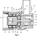
Figur 4 zeigt eine Seitenansicht eines alternativen erfindungsgemäßen Drehschieberventils in geschnittener Darstellung. - Das erfindungsgemäße Drehschieberventil weist ein Strömungsgehäuse 10 mit einem Einlass 12 und einem Auslass 14 auf, die im vorliegenden Ausführungsbeispiel in einem radial verlaufenden Einlassstutzen 16 und einem um 90° zum Einlassstutzen 16 versetzten, ebenfalls radial verlaufenden Auslassstutzen 18 ausgebildet sind. Im Strömungsgehäuse 10, welches im Wesentlichen hohlzylindrisch geformt ist, ist ein Drehschieberglied 20 auf einer Abtriebsachse 22 befestigt, welches eine Durchflussöffnung 24 aufweist, über die die fluidische Verbindung zwischen dem Einlass 12 und dem Auslass 14 hergestellt werden kann. Die Durchflussöffnung 24 ist in vorliegender Ausführung lediglich als sich etwa über den halben Umfang des ansonsten etwa zylindrischen Drehschiebergliedes 20 erstreckende Ausnehmung ausgeformt.
- Die Abtriebsachse 22 ist an ihrem einen axialen Ende in einer Aufnahmeöffnung 26 an einem das Strömungsgehäuse 10 verschließenden Boden 28 gelagert und an ihrem entgegengesetzten axialen Ende in einem Boden 30 eines Spalttopfes 32.
- Das Drehschieberventil weist einen Antriebsmotor 34 auf, der als zweiphasiger Klauenpolmotor ausgeführt ist, wobei jede Phase maximal vier Polpaare aufweist. Durch eine entsprechende Kommutierung, welche phasenversetzt für zwei Spulen 36 eines Stators 38 des Klauenpolmotors stattfindet, kann ein Rotor 40, der auf der Abtriebsachse 22 drehbar gelagert ist, gleichmäßig angetrieben und auf beliebige Drehpositionen verstellt werden.
- Der Rotor 40 ist vom Stator 38 durch den Spalttopf 32 getrennt, welcher einstückig mit einem Aktorgehäuse 42 ausgebildet ist, indem sich ein Kragen 43 radial nach außen vom Spalttopf 32 zum umliegenden Aktorgehäuse 42 erstreckt, der axial den Stator 38 begrenzt. Das Aktorgehäuse 42 umgibt den Antriebsmotor 34 radial und ist am Strömungsgehäuse 10 befestigt, so dass im radial Inneren des Strömungsgehäuses 10 zwischen dem Antriebsmotor 34 und dem Drehschieberglied 20 ein Raum 44 geschaffen wird, der axial durch den Spalttopf 32 und dessen Kragen 43 und radial durch das Aktorgehäuse 42 und das Strömungsgehäuse 10 begrenzt wird und an der axial gegenüberliegenden Seite durch den Boden 28 des Strömungsgehäuses 10 begrenzt wird, so dass dieser Raum 44 mit dem durch das Drehschieberglied 20 geregelten Fluid gefüllt ist. Des Weiteren ist ein Abstand zwischen dem Kragen 43 des Spalttopfes 32 und dem Drehschieberglied 20 vorhanden, so dass im Raum 44 axial zwischen dem Kragen 43 des Spalttopfes 32 und dem Drehschieberglied 20 erfindungsgemäß ein Wolfromgetriebe 46 angeordnet ist, mittels dessen die Bewegung des Antriebsmotors 34 mit einer hohen Übersetzung auf das Drehschieberglied 20 übertragen wird.
- Das Wolfromgetriebe 46 besteht aus einem Sonnenrad 48, welches drehfest mit dem Rotor 40 verbunden und auf der Abtriebsachse 22 gelagert ist und mit zwei Planetenrädern 50 kämmt, die im Ausführungsbeispiel gemäß der
Figuren 1 bis 3 auf Achsen 52 eines Planetenradträgers 54 drehbar gelagert sind. Der Planetenradträger 54 ist schwimmend im Drehschieberglied 20 gelagert. Die Planetenräder 50 greifen mit einem ersten axialen Abschnitt in ein erstes, feststehendes Hohlrad 56, welches an der Innenseite eines ringförmigen axialen Vorsprungs 58 ausgebildet ist, der sich vom Kragen 43 des Spalttopfes 32 axial zum Drehschieberglied 20 erstreckt. Ein zweiter axialer Abschnitt der Planetenräder 50 greift in ein zweites Hohlrad 60, welches an der radialen Innenseite eines ringförmigen Vorsprungs am Drehschieberglied 20 ausgebildet ist und entsprechend mit dem Drehschieberglied 20 gedreht wird. Das erste Hohlrad 56 unterschiedet sich vom zweiten Hohlrad 60 lediglich um wenige Zähne, wodurch bei Drehung des Antriebsmotors 34 eine sehr hohe Übersetzung entsteht und das Drehschieberglied 20 sehr genau eingestellt werden kann. - In der
Figur 2 sind des Weiteren am Planetenradträger 54 ausgebildete Füllstücke 62 zu erkennen, die in Umfangsrichtung zwischen den Planetenrädern 50 angeordnet sind und durch die die hydrodynamischen Verluste des im Kühlmittel laufenden Wolfromgetriebes 46 reduziert werden. - Bei dem Ausführungsbeispiel gemäß der
Figur 4 wird auf einen Planetenträger verzichtet. Stattdessen werden die Planetenräder 50 schwimmend zwischen den Hohlrädern 56, 60 und dem Sonnenrad 48 gelagert, indem sie axial zwischen dem Rotor 40 des Antriebsmotors 34 und Wandstücken des Drehschiebergliedes 20 drehbar im Fluid gehalten werden. - Wird der Stator 38 des Antriebsmotors 34 entsprechend bestromt, wird das entstehende magnetische Feld durch den Spalttopf 32 auf den Rotor 40 übertragen, der entsprechend mit dem Sonnenrad 48 auf der Abtriebsachse 22 gedreht wird. Durch die Drehung des Sonnenrades 48 rollen die Planetenräder 50 auf dem Sonnenrad 48 und dem feststehenden ersten Hohlrad 56 ab und übertragen durch die Zähnezahldifferenz die Bewegung mit sehr hoher Übersetzung auf das zweite Hohlrad 60 und damit auch auf das Drehschieberglied 20, welches somit zum Öffnen und Schließen einer Verbindung zwischen dem Einlass 12 und dem Auslass 14 gedreht wird.
- Der Raum 44, in dem sich das Wolfromgetriebe 46 und der Rotor 40 und das Drehschieberglied 20 befinden, ist mit dem zu förderndem Fluid gefüllt. Dies bedeutet, dass alle sich drehenden Teile in diesem Raum 44 angeordnet sind, so dass keine Dichtung entlang der sich drehenden Teile vorgenommen werden muss. Es ist lediglich das Strömungsgehäuse nach außen zum Aktorgehäuse abzudichten, welche jedoch beide still stehen, so dass eine statische Dichtung verwendet werden kann. Auf dynamische Dichtungen kann entsprechend vollständig verzichtet werden.
- Es sollte deutlich sein, dass verschiedene Modifikationen im Vergleich zu den Ausführungsbeispielen für den Fachmann naheliegen, ohne den Schutzbereich des Hauptanspruchs zu verlassen. So können Einlass und Auslass auch gegenüberliegend oder andersartig zueinander angeordnet werden oder mehrere Ein- und Auslässe ausgebildet werden, so dass die Durchströmungsöffnung oder -Öffnungen entsprechend im Drehschieberglied anders platziert werden. Auch können mehrere Planetenräder oder nur eines verwendet werden. Ebenso kann auf die Füllstücke gegebenenfalls verzichtet werden. Zusätzlich eignen sich auch andere insbesondere elektrisch kommutierte Antriebsmotoren als der beschriebene Klauenpolmotor. Auch sind andere koaxiale Umlaufgetriebe einsetzbar. Weitere konstruktive Änderungen sind selbstverständlich ebenfalls denkbar.
Claims (12)
- Drehschieberventil für ein Kraftfahrzeug miteinem Antriebsmotor (34),einem Getriebe (46), welches mittels des Antriebsmotors (34) in Drehung versetzbar ist,einem Drehschieberglied (20) mit zumindest einer Durchflussöffnung (24),einem Strömungsgehäuse (10), in dem das Drehschieberglied (20) gelagert ist und welches zumindest einen Einlass (12) und zumindest einen Auslass (14) aufweist, welche über die Durchflussöffnung (24) des Drehschiebergliedes (20) fluidisch verbindbar sind,dadurch gekennzeichnet, dassdas Getriebe ein hochübersetzendes koaxiales Umlaufgetriebe (46) ist, welches als Wolfromgetriebe ausgebildet ist, dessen zweites Hohlrad (60) an einer radialen Innenseite des Drehschiebergliedes (20) ausgebildet ist, und welches in einem Raum (44) angeordnet ist, der fluidisch mit der Durchflussöffnung (24) des Drehschiebergliedes (20) verbunden ist.
- Drehschieberventil für ein Kraftfahrzeug nach Anspruch 1,
dadurch gekennzeichnet, dass
der Raum (44) radial durch das Strömungsgehäuse (10) und ein mit dem Strömungsgehäuse (10) verbundenes Aktorgehäuse (42) begrenzt ist. - Drehschieberventil für ein Kraftfahrzeug nach Anspruch 1 oder 2,
dadurch gekennzeichnet, dass
der Rotor (40) des Antriebsmotors (34) in dem Raum (44) angeordnet ist, in dem das hochübersetzende koaxiale Umlaufgetriebe (46) angeordnet ist. - Drehschieberventil für ein Kraftfahrzeug nach Anspruch 3,
dadurch gekennzeichnet, dass
ein Stator (38) des Antriebsmotors (34) vom Rotor (40) durch einen Spalttopf (32) getrennt ist. - Drehschieberventil für ein Kraftfahrzeug nach Anspruch 4,
dadurch gekennzeichnet, dass
der Spalttopf (32) einstückig mit dem Aktorgehäuse (42) ausgebildet ist. - Drehschieberventil für ein Kraftfahrzeug nach Anspruch 4 oder 5,
dadurch gekennzeichnet, dass
der Spalttopf (32) einen sich radial erstreckenden Kragen (43) aufweist, der den Raum (44), in dem der Rotor (40) und das Wolfromgetriebe (46) angeordnet sind, axial in Richtung des Stators (38) begrenzt. - Drehschieberventil für ein Kraftfahrzeug nach Anspruch 6,
dadurch gekennzeichnet, dass
sich vom Kragen (43) des Spalttopfes (32) axial ein erstes Hohlrad (56) des Wolfromgetriebes (46) erstreckt. - Drehschieberventil für ein Kraftfahrzeug nach Anspruch 7,
dadurch gekennzeichnet, dass
der Rotor (40) des Antriebsmotors (34) mit einem Sonnenrad (48) verbunden ist, welches mit dem Rotor (40) auf einer Abtriebsachse (22) des Wolfromgetriebes (46) gelagert ist, welches mit zumindest einem Planetenrad (50) kämmt, das mit dem ersten Hohlrad (56) und dem zweiten Hohlrad (60) kämmt, wobei die Zähnezahlen der beiden Hohlräder (56, 60) unterschiedlich sind. - Drehschieberventil für ein Kraftfahrzeug nach Anspruch 8,
dadurch gekennzeichnet, dass
das Wolfromgetriebe (46) mehrere Planetenräder (50) aufweist, in deren Zwischenräumen Füllstücke (62) angeordnet sind, die an einem Planetenradträger (54) befestigt oder einstückig mit dem Planetenradträger (54) ausgebildet sind. - Drehschieberventil für ein Kraftfahrzeug nach einem der Ansprüche 8 oder 9,
dadurch gekennzeichnet, dass
die Planetenräder (50) auf Achsen (52) des freischwimmend gelagerten Planetenradträgers (54) gelagert sind. - Drehschieberventil für ein Kraftfahrzeug nach Anspruch 8,
dadurch gekennzeichnet, dass
die Planetenräder (50) freischwimmend ausgebildet sind. - Drehschieberventil für ein Kraftfahrzeug nach einem der vorhergehenden Ansprüche,
dadurch gekennzeichnet, dass
der Antriebsmotor (34) als zweiphasiger Klauenpolmotor ausgeführt ist.
Applications Claiming Priority (1)
| Application Number | Priority Date | Filing Date | Title |
|---|---|---|---|
| PCT/EP2019/059056 WO2020207574A1 (de) | 2019-04-10 | 2019-04-10 | Drehschieberventil für ein kraftfahrzeug |
Publications (2)
| Publication Number | Publication Date |
|---|---|
| EP3953620A1 EP3953620A1 (de) | 2022-02-16 |
| EP3953620B1 true EP3953620B1 (de) | 2024-04-03 |
Family
ID=66218070
Family Applications (1)
| Application Number | Title | Priority Date | Filing Date |
|---|---|---|---|
| EP19718106.8A Active EP3953620B1 (de) | 2019-04-10 | 2019-04-10 | Drehschieberventil für ein kraftfahrzeug |
Country Status (2)
| Country | Link |
|---|---|
| EP (1) | EP3953620B1 (de) |
| WO (1) | WO2020207574A1 (de) |
Families Citing this family (1)
| Publication number | Priority date | Publication date | Assignee | Title |
|---|---|---|---|---|
| GB201919194D0 (en) * | 2019-12-23 | 2020-02-05 | Eaton Intelligent Power Ltd | Ball valve with integral gear |
Citations (2)
| Publication number | Priority date | Publication date | Assignee | Title |
|---|---|---|---|---|
| DE202004019436U1 (de) * | 2004-12-16 | 2005-02-17 | Reinert-Ritz Gmbh | Absperrorgan aus Kunststoff für Fluidleitungen |
| DE102021103590A1 (de) * | 2020-08-28 | 2022-03-03 | Woco Industrietechnik Gmbh | Stellventil und Leitungssystem |
Family Cites Families (9)
| Publication number | Priority date | Publication date | Assignee | Title |
|---|---|---|---|---|
| FR2116921A5 (fr) * | 1970-12-11 | 1972-07-21 | Petroles Cie Francaise | Dispositif de commande d'ouverture et de fermeture d'une vanne equipee de son dispositif de securite automatique de fermeture |
| DE3926910A1 (de) * | 1989-08-16 | 1991-02-21 | Bosch Gmbh Robert | Leerlaufdrehsteller |
| CN2428645Y (zh) * | 2000-01-08 | 2001-05-02 | 胡彬 | 旋转锥芯脉冲电磁阀 |
| FR2837897B1 (fr) * | 2002-03-26 | 2008-04-04 | Valeo Thermique Moteur Sa | Vanne a commande electrique pour circuit de circulation de fluide |
| JP5389570B2 (ja) * | 2009-08-25 | 2014-01-15 | 株式会社不二工機 | 多方切換弁 |
| JP6149216B2 (ja) * | 2013-05-21 | 2017-06-21 | 株式会社テージーケー | 切替弁 |
| WO2015004646A1 (en) * | 2013-07-12 | 2015-01-15 | Padmini Vna Mechatronics Pvt. Ltd. | An automatic temperature control device for an internal combustion engine |
| DE102016119092B4 (de) * | 2016-10-07 | 2018-05-09 | Pierburg Gmbh | Aktuator für eine Verbrennungskraftmaschine |
| DE102017105696A1 (de) | 2017-03-16 | 2018-09-20 | Pierburg Gmbh | Drehschieberventil für den Einsatz im Kfz-Bereich |
-
2019
- 2019-04-10 WO PCT/EP2019/059056 patent/WO2020207574A1/de not_active Ceased
- 2019-04-10 EP EP19718106.8A patent/EP3953620B1/de active Active
Patent Citations (2)
| Publication number | Priority date | Publication date | Assignee | Title |
|---|---|---|---|---|
| DE202004019436U1 (de) * | 2004-12-16 | 2005-02-17 | Reinert-Ritz Gmbh | Absperrorgan aus Kunststoff für Fluidleitungen |
| DE102021103590A1 (de) * | 2020-08-28 | 2022-03-03 | Woco Industrietechnik Gmbh | Stellventil und Leitungssystem |
Also Published As
| Publication number | Publication date |
|---|---|
| EP3953620A1 (de) | 2022-02-16 |
| WO2020207574A1 (de) | 2020-10-15 |
Similar Documents
| Publication | Publication Date | Title |
|---|---|---|
| DE69629323T2 (de) | Permanentmagnetisch erregter Synchronmotor | |
| DE112011104525B4 (de) | Getriebeeinheit | |
| DE10150175A1 (de) | Magnetische Lüfterkupplung | |
| WO2018210740A1 (de) | Fördereinrichtung | |
| EP1857681B1 (de) | Drehschiebervakuumpumpe mit Spaltrohrmotor | |
| WO2018167043A1 (de) | Pumpenaggregat | |
| EP4198311A1 (de) | Schraubenspindelpumpe | |
| WO2018166967A1 (de) | Kreiselpumpenaggregat | |
| EP4677231A1 (de) | Pumpenventilanordnung | |
| EP3953620A1 (de) | Drehschieberventil für ein kraftfahrzeug | |
| EP2818725A1 (de) | Kreiselpumpe mit axial verschiebbarem, schliessbarem Laufrad | |
| EP3913267B1 (de) | Antriebsvorrichtung zum betätigen eines drehschiebers | |
| EP3953619B1 (de) | Drehschieberventil für ein kraftfahrzeug | |
| EP3596367B1 (de) | Drehschieberventil für den einsatz im kfz-bereich | |
| EP3542066B1 (de) | Zweiflutige strömungsmaschine | |
| DE112010001579T5 (de) | Kupplungseinrichtung | |
| WO2020103974A1 (de) | Hybridmodul sowie antriebsanordnung für ein kraftfahrzeug | |
| DE102017116732A1 (de) | Nockenwellenversteller zur variablen Einstellung der Ventilsteuerzeiten einer Brennkraftmaschine und Anordnung zur Abdichtung eines Nockenwellenverstellers | |
| DE102017223576A1 (de) | Kühlmittelpumpe zum Fördern eines Kühlmittels | |
| DE4234055C2 (de) | Spiralkompressor | |
| WO2018137952A1 (de) | Drehschieberventil | |
| DE112021002784T5 (de) | Doppelantriebs-Gerotorpumpe | |
| DE69709242T2 (de) | Heizvorrichtung mit viskoser Flüssigkeit zur Montage in einem begrenzten Montagebereich | |
| EP4259935B1 (de) | Pumpenvorrichtung für ein hydraulisches system eines kraftfahrzeugs, hydraulisches system | |
| DE3824686A1 (de) | Gerotor-motor/pumpe |
Legal Events
| Date | Code | Title | Description |
|---|---|---|---|
| STAA | Information on the status of an ep patent application or granted ep patent |
Free format text: STATUS: UNKNOWN |
|
| STAA | Information on the status of an ep patent application or granted ep patent |
Free format text: STATUS: THE INTERNATIONAL PUBLICATION HAS BEEN MADE |
|
| PUAI | Public reference made under article 153(3) epc to a published international application that has entered the european phase |
Free format text: ORIGINAL CODE: 0009012 |
|
| STAA | Information on the status of an ep patent application or granted ep patent |
Free format text: STATUS: REQUEST FOR EXAMINATION WAS MADE |
|
| 17P | Request for examination filed |
Effective date: 20211109 |
|
| AK | Designated contracting states |
Kind code of ref document: A1 Designated state(s): AL AT BE BG CH CY CZ DE DK EE ES FI FR GB GR HR HU IE IS IT LI LT LU LV MC MK MT NL NO PL PT RO RS SE SI SK SM TR |
|
| DAV | Request for validation of the european patent (deleted) | ||
| DAX | Request for extension of the european patent (deleted) | ||
| REG | Reference to a national code |
Ref country code: DE Ref legal event code: R079 Free format text: PREVIOUS MAIN CLASS: F16K0005040000 Ipc: F01P0007160000 Ref document number: 502019010965 Country of ref document: DE |
|
| GRAP | Despatch of communication of intention to grant a patent |
Free format text: ORIGINAL CODE: EPIDOSNIGR1 |
|
| STAA | Information on the status of an ep patent application or granted ep patent |
Free format text: STATUS: GRANT OF PATENT IS INTENDED |
|
| RIC1 | Information provided on ipc code assigned before grant |
Ipc: F16K 31/53 20060101ALI20231026BHEP Ipc: F16K 31/04 20060101ALI20231026BHEP Ipc: F01P 7/14 20060101ALI20231026BHEP Ipc: F16K 5/04 20060101ALI20231026BHEP Ipc: F01P 7/16 20060101AFI20231026BHEP |
|
| INTG | Intention to grant announced |
Effective date: 20231123 |
|
| GRAS | Grant fee paid |
Free format text: ORIGINAL CODE: EPIDOSNIGR3 |
|
| GRAA | (expected) grant |
Free format text: ORIGINAL CODE: 0009210 |
|
| STAA | Information on the status of an ep patent application or granted ep patent |
Free format text: STATUS: THE PATENT HAS BEEN GRANTED |
|
| AK | Designated contracting states |
Kind code of ref document: B1 Designated state(s): AL AT BE BG CH CY CZ DE DK EE ES FI FR GB GR HR HU IE IS IT LI LT LU LV MC MK MT NL NO PL PT RO RS SE SI SK SM TR |
|
| REG | Reference to a national code |
Ref country code: CH Ref legal event code: EP |
|
| REG | Reference to a national code |
Ref country code: DE Ref legal event code: R096 Ref document number: 502019010965 Country of ref document: DE |
|
| REG | Reference to a national code |
Ref country code: IE Ref legal event code: FG4D Free format text: LANGUAGE OF EP DOCUMENT: GERMAN |
|
| REG | Reference to a national code |
Ref country code: LT Ref legal event code: MG9D |
|
| REG | Reference to a national code |
Ref country code: NL Ref legal event code: MP Effective date: 20240403 |
|
| PG25 | Lapsed in a contracting state [announced via postgrant information from national office to epo] |
Ref country code: NL Free format text: LAPSE BECAUSE OF FAILURE TO SUBMIT A TRANSLATION OF THE DESCRIPTION OR TO PAY THE FEE WITHIN THE PRESCRIBED TIME-LIMIT Effective date: 20240403 |
|
| PG25 | Lapsed in a contracting state [announced via postgrant information from national office to epo] |
Ref country code: NL Free format text: LAPSE BECAUSE OF FAILURE TO SUBMIT A TRANSLATION OF THE DESCRIPTION OR TO PAY THE FEE WITHIN THE PRESCRIBED TIME-LIMIT Effective date: 20240403 |
|
| PG25 | Lapsed in a contracting state [announced via postgrant information from national office to epo] |
Ref country code: IS Free format text: LAPSE BECAUSE OF FAILURE TO SUBMIT A TRANSLATION OF THE DESCRIPTION OR TO PAY THE FEE WITHIN THE PRESCRIBED TIME-LIMIT Effective date: 20240803 |
|
| PG25 | Lapsed in a contracting state [announced via postgrant information from national office to epo] |
Ref country code: BG Free format text: LAPSE BECAUSE OF FAILURE TO SUBMIT A TRANSLATION OF THE DESCRIPTION OR TO PAY THE FEE WITHIN THE PRESCRIBED TIME-LIMIT Effective date: 20240403 |
|
| PG25 | Lapsed in a contracting state [announced via postgrant information from national office to epo] |
Ref country code: HR Free format text: LAPSE BECAUSE OF FAILURE TO SUBMIT A TRANSLATION OF THE DESCRIPTION OR TO PAY THE FEE WITHIN THE PRESCRIBED TIME-LIMIT Effective date: 20240403 Ref country code: FI Free format text: LAPSE BECAUSE OF FAILURE TO SUBMIT A TRANSLATION OF THE DESCRIPTION OR TO PAY THE FEE WITHIN THE PRESCRIBED TIME-LIMIT Effective date: 20240403 |
|
| PG25 | Lapsed in a contracting state [announced via postgrant information from national office to epo] |
Ref country code: GR Free format text: LAPSE BECAUSE OF FAILURE TO SUBMIT A TRANSLATION OF THE DESCRIPTION OR TO PAY THE FEE WITHIN THE PRESCRIBED TIME-LIMIT Effective date: 20240704 |
|
| PG25 | Lapsed in a contracting state [announced via postgrant information from national office to epo] |
Ref country code: PT Free format text: LAPSE BECAUSE OF FAILURE TO SUBMIT A TRANSLATION OF THE DESCRIPTION OR TO PAY THE FEE WITHIN THE PRESCRIBED TIME-LIMIT Effective date: 20240805 |
|
| PG25 | Lapsed in a contracting state [announced via postgrant information from national office to epo] |
Ref country code: ES Free format text: LAPSE BECAUSE OF FAILURE TO SUBMIT A TRANSLATION OF THE DESCRIPTION OR TO PAY THE FEE WITHIN THE PRESCRIBED TIME-LIMIT Effective date: 20240403 |
|
| PG25 | Lapsed in a contracting state [announced via postgrant information from national office to epo] |
Ref country code: CZ Free format text: LAPSE BECAUSE OF FAILURE TO SUBMIT A TRANSLATION OF THE DESCRIPTION OR TO PAY THE FEE WITHIN THE PRESCRIBED TIME-LIMIT Effective date: 20240403 |
|
| PG25 | Lapsed in a contracting state [announced via postgrant information from national office to epo] |
Ref country code: PL Free format text: LAPSE BECAUSE OF FAILURE TO SUBMIT A TRANSLATION OF THE DESCRIPTION OR TO PAY THE FEE WITHIN THE PRESCRIBED TIME-LIMIT Effective date: 20240403 |
|
| PG25 | Lapsed in a contracting state [announced via postgrant information from national office to epo] |
Ref country code: LV Free format text: LAPSE BECAUSE OF FAILURE TO SUBMIT A TRANSLATION OF THE DESCRIPTION OR TO PAY THE FEE WITHIN THE PRESCRIBED TIME-LIMIT Effective date: 20240403 |
|
| PG25 | Lapsed in a contracting state [announced via postgrant information from national office to epo] |
Ref country code: PT Free format text: LAPSE BECAUSE OF FAILURE TO SUBMIT A TRANSLATION OF THE DESCRIPTION OR TO PAY THE FEE WITHIN THE PRESCRIBED TIME-LIMIT Effective date: 20240805 Ref country code: PL Free format text: LAPSE BECAUSE OF FAILURE TO SUBMIT A TRANSLATION OF THE DESCRIPTION OR TO PAY THE FEE WITHIN THE PRESCRIBED TIME-LIMIT Effective date: 20240403 Ref country code: NO Free format text: LAPSE BECAUSE OF FAILURE TO SUBMIT A TRANSLATION OF THE DESCRIPTION OR TO PAY THE FEE WITHIN THE PRESCRIBED TIME-LIMIT Effective date: 20240703 Ref country code: LV Free format text: LAPSE BECAUSE OF FAILURE TO SUBMIT A TRANSLATION OF THE DESCRIPTION OR TO PAY THE FEE WITHIN THE PRESCRIBED TIME-LIMIT Effective date: 20240403 Ref country code: IS Free format text: LAPSE BECAUSE OF FAILURE TO SUBMIT A TRANSLATION OF THE DESCRIPTION OR TO PAY THE FEE WITHIN THE PRESCRIBED TIME-LIMIT Effective date: 20240803 Ref country code: HR Free format text: LAPSE BECAUSE OF FAILURE TO SUBMIT A TRANSLATION OF THE DESCRIPTION OR TO PAY THE FEE WITHIN THE PRESCRIBED TIME-LIMIT Effective date: 20240403 Ref country code: GR Free format text: LAPSE BECAUSE OF FAILURE TO SUBMIT A TRANSLATION OF THE DESCRIPTION OR TO PAY THE FEE WITHIN THE PRESCRIBED TIME-LIMIT Effective date: 20240704 Ref country code: FI Free format text: LAPSE BECAUSE OF FAILURE TO SUBMIT A TRANSLATION OF THE DESCRIPTION OR TO PAY THE FEE WITHIN THE PRESCRIBED TIME-LIMIT Effective date: 20240403 Ref country code: ES Free format text: LAPSE BECAUSE OF FAILURE TO SUBMIT A TRANSLATION OF THE DESCRIPTION OR TO PAY THE FEE WITHIN THE PRESCRIBED TIME-LIMIT Effective date: 20240403 Ref country code: CZ Free format text: LAPSE BECAUSE OF FAILURE TO SUBMIT A TRANSLATION OF THE DESCRIPTION OR TO PAY THE FEE WITHIN THE PRESCRIBED TIME-LIMIT Effective date: 20240403 Ref country code: BG Free format text: LAPSE BECAUSE OF FAILURE TO SUBMIT A TRANSLATION OF THE DESCRIPTION OR TO PAY THE FEE WITHIN THE PRESCRIBED TIME-LIMIT Effective date: 20240403 Ref country code: RS Free format text: LAPSE BECAUSE OF FAILURE TO SUBMIT A TRANSLATION OF THE DESCRIPTION OR TO PAY THE FEE WITHIN THE PRESCRIBED TIME-LIMIT Effective date: 20240703 |
|
| REG | Reference to a national code |
Ref country code: CH Ref legal event code: PL |
|
| PG25 | Lapsed in a contracting state [announced via postgrant information from national office to epo] |
Ref country code: LU Free format text: LAPSE BECAUSE OF NON-PAYMENT OF DUE FEES Effective date: 20240410 |
|
| REG | Reference to a national code |
Ref country code: BE Ref legal event code: MM Effective date: 20240430 |
|
| PG25 | Lapsed in a contracting state [announced via postgrant information from national office to epo] |
Ref country code: LU Free format text: LAPSE BECAUSE OF NON-PAYMENT OF DUE FEES Effective date: 20240410 |
|
| REG | Reference to a national code |
Ref country code: DE Ref legal event code: R097 Ref document number: 502019010965 Country of ref document: DE |
|
| PG25 | Lapsed in a contracting state [announced via postgrant information from national office to epo] |
Ref country code: DK Free format text: LAPSE BECAUSE OF FAILURE TO SUBMIT A TRANSLATION OF THE DESCRIPTION OR TO PAY THE FEE WITHIN THE PRESCRIBED TIME-LIMIT Effective date: 20240403 |
|
| PG25 | Lapsed in a contracting state [announced via postgrant information from national office to epo] |
Ref country code: BE Free format text: LAPSE BECAUSE OF NON-PAYMENT OF DUE FEES Effective date: 20240430 |
|
| PG25 | Lapsed in a contracting state [announced via postgrant information from national office to epo] |
Ref country code: EE Free format text: LAPSE BECAUSE OF FAILURE TO SUBMIT A TRANSLATION OF THE DESCRIPTION OR TO PAY THE FEE WITHIN THE PRESCRIBED TIME-LIMIT Effective date: 20240403 |
|
| PG25 | Lapsed in a contracting state [announced via postgrant information from national office to epo] |
Ref country code: RO Free format text: LAPSE BECAUSE OF FAILURE TO SUBMIT A TRANSLATION OF THE DESCRIPTION OR TO PAY THE FEE WITHIN THE PRESCRIBED TIME-LIMIT Effective date: 20240403 Ref country code: SK Free format text: LAPSE BECAUSE OF FAILURE TO SUBMIT A TRANSLATION OF THE DESCRIPTION OR TO PAY THE FEE WITHIN THE PRESCRIBED TIME-LIMIT Effective date: 20240403 |
|
| PG25 | Lapsed in a contracting state [announced via postgrant information from national office to epo] |
Ref country code: SM Free format text: LAPSE BECAUSE OF FAILURE TO SUBMIT A TRANSLATION OF THE DESCRIPTION OR TO PAY THE FEE WITHIN THE PRESCRIBED TIME-LIMIT Effective date: 20240403 |
|
| PG25 | Lapsed in a contracting state [announced via postgrant information from national office to epo] |
Ref country code: SM Free format text: LAPSE BECAUSE OF FAILURE TO SUBMIT A TRANSLATION OF THE DESCRIPTION OR TO PAY THE FEE WITHIN THE PRESCRIBED TIME-LIMIT Effective date: 20240403 Ref country code: SK Free format text: LAPSE BECAUSE OF FAILURE TO SUBMIT A TRANSLATION OF THE DESCRIPTION OR TO PAY THE FEE WITHIN THE PRESCRIBED TIME-LIMIT Effective date: 20240403 Ref country code: RO Free format text: LAPSE BECAUSE OF FAILURE TO SUBMIT A TRANSLATION OF THE DESCRIPTION OR TO PAY THE FEE WITHIN THE PRESCRIBED TIME-LIMIT Effective date: 20240403 Ref country code: EE Free format text: LAPSE BECAUSE OF FAILURE TO SUBMIT A TRANSLATION OF THE DESCRIPTION OR TO PAY THE FEE WITHIN THE PRESCRIBED TIME-LIMIT Effective date: 20240403 Ref country code: DK Free format text: LAPSE BECAUSE OF FAILURE TO SUBMIT A TRANSLATION OF THE DESCRIPTION OR TO PAY THE FEE WITHIN THE PRESCRIBED TIME-LIMIT Effective date: 20240403 Ref country code: BE Free format text: LAPSE BECAUSE OF NON-PAYMENT OF DUE FEES Effective date: 20240430 Ref country code: MC Free format text: LAPSE BECAUSE OF FAILURE TO SUBMIT A TRANSLATION OF THE DESCRIPTION OR TO PAY THE FEE WITHIN THE PRESCRIBED TIME-LIMIT Effective date: 20240403 Ref country code: CH Free format text: LAPSE BECAUSE OF NON-PAYMENT OF DUE FEES Effective date: 20240430 |
|
| PLBE | No opposition filed within time limit |
Free format text: ORIGINAL CODE: 0009261 |
|
| STAA | Information on the status of an ep patent application or granted ep patent |
Free format text: STATUS: NO OPPOSITION FILED WITHIN TIME LIMIT |
|
| 26N | No opposition filed |
Effective date: 20250106 |
|
| PG25 | Lapsed in a contracting state [announced via postgrant information from national office to epo] |
Ref country code: IE Free format text: LAPSE BECAUSE OF NON-PAYMENT OF DUE FEES Effective date: 20240410 |
|
| PG25 | Lapsed in a contracting state [announced via postgrant information from national office to epo] |
Ref country code: SI Free format text: LAPSE BECAUSE OF FAILURE TO SUBMIT A TRANSLATION OF THE DESCRIPTION OR TO PAY THE FEE WITHIN THE PRESCRIBED TIME-LIMIT Effective date: 20240403 |
|
| REG | Reference to a national code |
Ref country code: AT Ref legal event code: MM01 Ref document number: 1672536 Country of ref document: AT Kind code of ref document: T Effective date: 20240410 |
|
| PGFP | Annual fee paid to national office [announced via postgrant information from national office to epo] |
Ref country code: DE Payment date: 20250422 Year of fee payment: 7 |
|
| PGFP | Annual fee paid to national office [announced via postgrant information from national office to epo] |
Ref country code: GB Payment date: 20250423 Year of fee payment: 7 |
|
| PGFP | Annual fee paid to national office [announced via postgrant information from national office to epo] |
Ref country code: FR Payment date: 20250425 Year of fee payment: 7 |
|
| PG25 | Lapsed in a contracting state [announced via postgrant information from national office to epo] |
Ref country code: AT Free format text: LAPSE BECAUSE OF NON-PAYMENT OF DUE FEES Effective date: 20240410 |
|
| PG25 | Lapsed in a contracting state [announced via postgrant information from national office to epo] |
Ref country code: CY Free format text: LAPSE BECAUSE OF FAILURE TO SUBMIT A TRANSLATION OF THE DESCRIPTION OR TO PAY THE FEE WITHIN THE PRESCRIBED TIME-LIMIT; INVALID AB INITIO Effective date: 20190410 |
|
| PG25 | Lapsed in a contracting state [announced via postgrant information from national office to epo] |
Ref country code: HU Free format text: LAPSE BECAUSE OF FAILURE TO SUBMIT A TRANSLATION OF THE DESCRIPTION OR TO PAY THE FEE WITHIN THE PRESCRIBED TIME-LIMIT; INVALID AB INITIO Effective date: 20190410 |
|
| PG25 | Lapsed in a contracting state [announced via postgrant information from national office to epo] |
Ref country code: SE Free format text: LAPSE BECAUSE OF FAILURE TO SUBMIT A TRANSLATION OF THE DESCRIPTION OR TO PAY THE FEE WITHIN THE PRESCRIBED TIME-LIMIT Effective date: 20240403 |
|
| PG25 | Lapsed in a contracting state [announced via postgrant information from national office to epo] |
Ref country code: IT Free format text: LAPSE BECAUSE OF FAILURE TO SUBMIT A TRANSLATION OF THE DESCRIPTION OR TO PAY THE FEE WITHIN THE PRESCRIBED TIME-LIMIT Effective date: 20240403 |
|
| REG | Reference to a national code |
Ref country code: DE Ref legal event code: R082 Ref document number: 502019010965 Country of ref document: DE |