EP3953573B1 - Improved rotating combustion machine - Google Patents
Improved rotating combustion machine Download PDFInfo
- Publication number
- EP3953573B1 EP3953573B1 EP20723929.4A EP20723929A EP3953573B1 EP 3953573 B1 EP3953573 B1 EP 3953573B1 EP 20723929 A EP20723929 A EP 20723929A EP 3953573 B1 EP3953573 B1 EP 3953573B1
- Authority
- EP
- European Patent Office
- Prior art keywords
- machine
- sector
- combustion chamber
- rotors
- rotation
- Prior art date
- Legal status (The legal status is an assumption and is not a legal conclusion. Google has not performed a legal analysis and makes no representation as to the accuracy of the status listed.)
- Active
Links
Images

Classifications
-
- F—MECHANICAL ENGINEERING; LIGHTING; HEATING; WEAPONS; BLASTING
- F02—COMBUSTION ENGINES; HOT-GAS OR COMBUSTION-PRODUCT ENGINE PLANTS
- F02B—INTERNAL-COMBUSTION PISTON ENGINES; COMBUSTION ENGINES IN GENERAL
- F02B53/00—Internal-combustion aspects of rotary-piston or oscillating-piston engines
-
- F—MECHANICAL ENGINEERING; LIGHTING; HEATING; WEAPONS; BLASTING
- F01—MACHINES OR ENGINES IN GENERAL; ENGINE PLANTS IN GENERAL; STEAM ENGINES
- F01C—ROTARY-PISTON OR OSCILLATING-PISTON MACHINES OR ENGINES
- F01C1/00—Rotary-piston machines or engines
- F01C1/02—Rotary-piston machines or engines of arcuate-engagement type, i.e. with circular translatory movement of co-operating members, each member having the same number of teeth or tooth-equivalents
- F01C1/063—Rotary-piston machines or engines of arcuate-engagement type, i.e. with circular translatory movement of co-operating members, each member having the same number of teeth or tooth-equivalents with coaxially-mounted members having continuously-changing circumferential spacing between them
- F01C1/077—Rotary-piston machines or engines of arcuate-engagement type, i.e. with circular translatory movement of co-operating members, each member having the same number of teeth or tooth-equivalents with coaxially-mounted members having continuously-changing circumferential spacing between them having toothed-gearing type drive
-
- F—MECHANICAL ENGINEERING; LIGHTING; HEATING; WEAPONS; BLASTING
- F01—MACHINES OR ENGINES IN GENERAL; ENGINE PLANTS IN GENERAL; STEAM ENGINES
- F01C—ROTARY-PISTON OR OSCILLATING-PISTON MACHINES OR ENGINES
- F01C21/00—Component parts, details or accessories not provided for in groups F01C1/00 - F01C20/00
- F01C21/06—Heating; Cooling; Heat insulation
-
- F—MECHANICAL ENGINEERING; LIGHTING; HEATING; WEAPONS; BLASTING
- F02—COMBUSTION ENGINES; HOT-GAS OR COMBUSTION-PRODUCT ENGINE PLANTS
- F02B—INTERNAL-COMBUSTION PISTON ENGINES; COMBUSTION ENGINES IN GENERAL
- F02B47/00—Methods of operating engines involving adding non-fuel substances or anti-knock agents to combustion air, fuel, or fuel-air mixtures of engines
- F02B47/02—Methods of operating engines involving adding non-fuel substances or anti-knock agents to combustion air, fuel, or fuel-air mixtures of engines the substances being water or steam
-
- Y—GENERAL TAGGING OF NEW TECHNOLOGICAL DEVELOPMENTS; GENERAL TAGGING OF CROSS-SECTIONAL TECHNOLOGIES SPANNING OVER SEVERAL SECTIONS OF THE IPC; TECHNICAL SUBJECTS COVERED BY FORMER USPC CROSS-REFERENCE ART COLLECTIONS [XRACs] AND DIGESTS
- Y02—TECHNOLOGIES OR APPLICATIONS FOR MITIGATION OR ADAPTATION AGAINST CLIMATE CHANGE
- Y02T—CLIMATE CHANGE MITIGATION TECHNOLOGIES RELATED TO TRANSPORTATION
- Y02T10/00—Road transport of goods or passengers
- Y02T10/10—Internal combustion engine [ICE] based vehicles
- Y02T10/12—Improving ICE efficiencies
Definitions
- the present invention generically relates to an improved rotating internal combustion machine, of the orbiting piston type, such as can be seen for example in US-A-1329625 , typically adapted to assume the configuration of a driving machine - such as a hydraulic turbine or, for example, a four or two-stroke combustion engine - which, as known, in the field of fluid machines, provides the output mechanical energy to the shaft of the machine at the expense of the energy of the processed operating fluid (air-fuel mixture).
- a driving machine - such as a hydraulic turbine or, for example, a four or two-stroke combustion engine -
- reciprocating internal combustion engines are quite common driving machines which allow converting the chemical energy of an air-fuel mixture (such as gasoline, diesel, liquid propane gas (LPG) or methane) into mechanical work made available to the driving shaft and, more generally, to the transmission system; they are used, in particular, for the propulsion of vehicles, such as, for example, cars for civil use, racing cars, motorcycles, trains, mopeds, agricultural machinery or gardening machinery (lawnmowers, to name but one).
- an air-fuel mixture such as gasoline, diesel, liquid propane gas (LPG) or methane
- LPG liquid propane gas
- methane methane
- thermodynamic loss factors are related to the combustion conditions and to the heat losses, according to the type of thermodynamic cycle they perform.
- the kinematic and dynamic loss factors are related to the typical configuration of this type of engine, distinguished by pistons sliding within cylinders and adapted to feed the driving shaft into rotation through a conventional rod-and-crank kinematic mechanism.
- timing devices of such reciprocating engines - e.g. comprising camshafts, which control the intake and exhaust poppet valves - generate mechanical losses, which subtract a share of the energy absorbed by the engine for its operation, thereby reducing the useful energy made available by the engine to the user.
- Such a machine has a stator having a toroidal chamber, which surrounds at least two coaxial and integral rotors, each with respective pistons sliding in such a toroidal chamber.
- the rotors are connected, through a mechanical transmission, to a primary shaft, which acts as a driving shaft or as a driven shaft, according to whether the machine is in operating machine configuration or in driving machine configuration, respectively.
- This mechanical transmission has two elliptical profile toothed wheels, each of which is connected to one of the rotors; the toothed wheels each engage an additional toothed wheel belonging to a pair of toothed wheels also with an elliptical profile, which are integrally keyed to the aforementioned primary shaft so that their major semi-axles are substantially perpendicular.
- the rotors feed the pistons according to a reciprocating pulsating motion which causes them to move towards and away during their rotation motion and to follow each other in the toroidal chamber.
- the volume comprised between successive pistons which rotate following each other in the toroidal chamber of the stator varies continuously between a minimum and a maximum value, similarly to the volume delimited in the cylinder by the piston during the operation of a reciprocating machine.
- the moving masses rotate about longitudinal axes with respect to which the masses themselves are arranged in a substantially symmetrical manner.
- a machine of this type can be improved, because elliptical profile toothed wheels are more complex and of more complicated manufacture than circular section wheels, precisely because of their axial dissymmetry.
- the transmission by providing the engagement of the corresponding toothed wheels, imposes the offset of the primary shaft with respect to the rotation axis of the rotors, to the detriment of the compactness of the machine.
- the orbiting piston rotating machine under Italian Patent no. 1378900 when configured as a driving machine, displays, as the main drawback, the fact that the torus-shaped sector of the annular inner chamber in which the expansion of the operating fluid following ignition takes place - and which, from a thermal point of view, is inevitably more stressed than the other sectors, with consequent expansions which differ from the remaining sectors of such annular inner chamber obtained in the stator - is not adequately cooled.
- the improved rotating combustion machine of the current invention allows to effectively cool the toroidal sector of the annular inner chamber of the stator directly concerned by the expansion of the operating fluid.
- the improved rotating combustion machine of the invention comprises an injection circuit, cooperating with the stator to convey a pressurized cooling fluid in nebulized or sprayed form into the expansion sector of the inner combustion chamber, the cooling fluid being contained in a service tank belonging to the injection circuit itself, as soon as the operating fluid has been combusted by the ignition means and during the rotation of the mechanical transmission means and the one or more rotors about the linear axis defined by the mechanical transmission means.
- the improved rotating combustion machine of the invention allows to lower, compared to the equivalent prior art, the value of the temperatures developed during the expansion stroke of the operating fluid in the torus-shaped sector of the annular inner chamber of the stator, immediately after its combustion by the ignition means, to the advantage of the duration of the structural integrity of the machine parts.
- the improved rotating combustion machine of the current invention achieves a thermal balance in the disposal of the heat produced by the combustion of the operating fluid determined by the orbiting pistons while rotating in the toroidal annular inner chamber of the stator better than that which can be achieved with equivalent machines of known type, e.g. the machine described in Italian Patent no. 1378900 .
- the improved rotating combustion machine of the present invention allows to recover the heat produced by the combustion of the operating fluid during the expansion stroke, consequent to its ignition, in the respective toroidal sector of the annular inner chamber of the stator, thus avoiding its disadvantageous dispersion into the environment and its absorption by the machine members, currently found in similar known machines; it follows, quite advantageously, that the operation of the cooling fluid injection circuit, provided in the machine of the invention, determines a greater energy contribution with a decrease in "specific consumption", meaning as the ratio between energy supplied by the fuel and energy obtained by the expansion.
- the thermal energy produced in the expansion chamber of the rotating machine of the invention is therefore transformed by the nebulized cooling fluid "shot" directly into the expansion sector of the combustion chamber into mechanical energy which is conveniently added to the mechanical energy obtained from the conversion of the energy of the fuel, thus increasing the mechanical energy supplied to the machine shaft, the number and size of the orbiting pistons being equal.
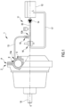
- the improved rotating combustion machine of the invention typically a four-stroke, spark-ignition engine, operating according to an Otto cycle, is diagrammatically shown in figure 1 , where it is indicated by reference numeral 1 as a whole.
- such a rotating combustion machine 1 comprises, according to the technical teachings suggested by Italian Patent no 1378900 here fully quoted again for reference:
- the improved rotating combustion machine 1 comprises an injection circuit, indicated as a whole by reference numeral 11, cooperating with the stator 2 to convey a pressurized cooling fluid L (typically water) in nebulized or sprayed form into the expansion sector E of the inner combustion chamber 3, the cooling fluid being contained in a service tank 12 belonging to the injection circuit 11, once the operating fluid has been combusted by the ignition means 8 and during the rotation of the mechanical transmission means 9 and of the rotors 7a, 7b about the linear axis Y.
- a pressurized cooling fluid L typically water
- the injection circuit 11 comprises a main delivery pipe 13 connected to the upper part P of the expansion sector E of the internal combustion chamber 3 defined within the stator 2.
- the injection circuit 11 appropriately further comprises pumping means, such as at least a volumetric pump 14, adapted to draw the cooling fluid L from the service tank 12 and introduce it under pressure into the expansion sector E of the internal combustion chamber 3.
- pumping means such as at least a volumetric pump 14, adapted to draw the cooling fluid L from the service tank 12 and introduce it under pressure into the expansion sector E of the internal combustion chamber 3.
- the injection circuit 11 includes a spray nozzle, not shown in the accompanying figures, facing the expansion sector E of the internal combustion chamber 3 and adapted to nebulize or spray the cooling fluid L.
- the aforesaid spray nozzle is arranged at the first end 13a of the main delivery pipe 13, the one directly facing (and communicating with, or facing) the expansion sector E of the internal combustion chamber 3.
- the injection circuit 11 further comprises a non-return valve 15 arranged downstream of the volumetric pump 14 and upstream of the first end 13a of the main delivery pipe 13.
- the non-return valve 15 is arranged at a second end 13b of the main flow pipe 13, opposite to the first end 13a defined above.
- the injection circuit 11 of the cooling fluid L further comprises a compensator 16 arranged downstream of the volumetric pump 14, in line with this in the initial duct 32 of the injection circuit 11.
- the injection circuit 11 further comprises an auxiliary return pipe 17 provided with valve means, such as a solenoid valve, which normally take an open position when the cooling fluid L is introduced under pressure into the expansion sector E of the inner combustion chamber 3 of the volumetric pump 14 and a closed position when the cooling fluid L must remain in the service tank 12 for any reason.
- valve means such as a solenoid valve
- the mechanical transmission means 9 are of the type indicated in the Italian Patent no. 1378900 , comprising:
- the transverse levers 25, 26 develop in a transverse direction to the linear axis of rotation defined by the primary shaft 10 of the mechanical transmission means 9 and are arranged axially close to each other on planes which are mutually distinct but parallel, thus defining longitudinal directions of development which are mutually offset according to a cross-like configuration.
- Figure 2 shows that, preferably, the eccentric means 29 project longitudinally and orthogonally from a side face 21a of each of the satellite toothed wheels 21 on the primitive diameter of which they are positioned, at a point different from the center of the satellite toothed wheels 21; this design concept gives rise to the eccentricity with which the interconnection hubs 23, 24 are connected to the satellite toothed wheels 21.
- the eccentric means 29 comprise, preferably but not exclusively, two projecting pins 30, 31 engaged in their respective slotted radial cams 27, 28 within which the projecting pins 30, 31 themselves slide during the rotation of the interconnecting hubs 23, 24 and the rotors 7a, 7b about the linear axis Y, as can be seen from the combined arrangement of figures 3a, 4a and 5a .
- the sliding of the orbiting pistons 6 in the inner combustion chamber 3 takes place simultaneously to the rotation of the rotors 7a, 7b, of the supporting planetary rotor 20 and the interconnection hubs 23, 24 about the linear axis Y and the rotation of the satellite toothed wheels 21 about the fixed solar toothed wheel 19 and the sliding of the eccentric means 29 in the slotted radial cams 27, 28.
- the ignition means 8 preferably comprise a spark plug 22 of the traditional type, clearly visible in figures 2 , 3 , 4 and 5 .
- the mechanical transmission means may comprise a number of interconnecting hubs and transverse connecting levers different from the one described above and shown in the appended figures; such a number varies according to the number of rotors provided in the rotating combustion engine of the current invention.
Landscapes
- Engineering & Computer Science (AREA)
- Mechanical Engineering (AREA)
- General Engineering & Computer Science (AREA)
- Chemical & Material Sciences (AREA)
- Combustion & Propulsion (AREA)
- Reciprocating Pumps (AREA)
- Air Bags (AREA)
- Noodles (AREA)
- Ignition Installations For Internal Combustion Engines (AREA)
Description
- The present invention generically relates to an improved rotating internal combustion machine, of the orbiting piston type, such as can be seen for example in
US-A-1329625 , typically adapted to assume the configuration of a driving machine - such as a hydraulic turbine or, for example, a four or two-stroke combustion engine - which, as known, in the field of fluid machines, provides the output mechanical energy to the shaft of the machine at the expense of the energy of the processed operating fluid (air-fuel mixture). - As known, reciprocating internal combustion engines are quite common driving machines which allow converting the chemical energy of an air-fuel mixture (such as gasoline, diesel, liquid propane gas (LPG) or methane) into mechanical work made available to the driving shaft and, more generally, to the transmission system; they are used, in particular, for the propulsion of vehicles, such as, for example, cars for civil use, racing cars, motorcycles, trains, mopeds, agricultural machinery or gardening machinery (lawnmowers, to name but one).
- It is also known that the energy efficiency of these types of engine depends on both thermodynamic loss factors and on kinematic and dynamic loss factors; the thermodynamic factors are related to the combustion conditions and to the heat losses, according to the type of thermodynamic cycle they perform.
- On the other hand, the kinematic and dynamic loss factors are related to the typical configuration of this type of engine, distinguished by pistons sliding within cylinders and adapted to feed the driving shaft into rotation through a conventional rod-and-crank kinematic mechanism.
- Furthermore, the timing devices of such reciprocating engines - e.g. comprising camshafts, which control the intake and exhaust poppet valves - generate mechanical losses, which subtract a share of the energy absorbed by the engine for its operation, thereby reducing the useful energy made available by the engine to the user.
- Similarly, operating machines, such as pumps, fans, and compressors, have the same structure as the reciprocating piston machines but the mechanical losses can be directly attributed to the dynamic efficiency of such configuration in these cases. A revolutionary driving/operating machine is also known from the technical teachings suggested by
Italian Patent no. 1263709 - Such a machine has a stator having a toroidal chamber, which surrounds at least two coaxial and integral rotors, each with respective pistons sliding in such a toroidal chamber.
- The rotors are connected, through a mechanical transmission, to a primary shaft, which acts as a driving shaft or as a driven shaft, according to whether the machine is in operating machine configuration or in driving machine configuration, respectively.
- This mechanical transmission has two elliptical profile toothed wheels, each of which is connected to one of the rotors; the toothed wheels each engage an additional toothed wheel belonging to a pair of toothed wheels also with an elliptical profile, which are integrally keyed to the aforementioned primary shaft so that their major semi-axles are substantially perpendicular.
- In this manner, the rotors feed the pistons according to a reciprocating pulsating motion which causes them to move towards and away during their rotation motion and to follow each other in the toroidal chamber.
- The volume comprised between successive pistons which rotate following each other in the toroidal chamber of the stator varies continuously between a minimum and a maximum value, similarly to the volume delimited in the cylinder by the piston during the operation of a reciprocating machine.
- The most obvious advantages obtained by such a driving/rotating machine with respect to the reciprocating machines of the prior art known at the time are determined by its dynamic balancing.
- Indeed, the moving masses rotate about longitudinal axes with respect to which the masses themselves are arranged in a substantially symmetrical manner. Although appreciated, a machine of this type can be improved, because elliptical profile toothed wheels are more complex and of more complicated manufacture than circular section wheels, precisely because of their axial dissymmetry.
- Furthermore, the transmission, by providing the engagement of the corresponding toothed wheels, imposes the offset of the primary shaft with respect to the rotation axis of the rotors, to the detriment of the compactness of the machine.
- Such drawbacks are solved by an improved rotating type machine, as described in
Italian patent no. 1378900 - Furthermore, the rotating machine referred to in
Italian Patent no. 1378900 - Additionally, the orbiting piston rotating machine described and claimed in
Italian Patent no. 1378900 - reduction of the power (in terms of horsepower or kilowatts) needed to supply and put the machine into operation, in particular the pistons which act on the operating fluid (combustion fluid - typically air - or a combustion supporter-fuel mixture);
- elimination of the timing system, typical of reciprocating machines;
- in driving machine configuration, the processing (burning) of the operating fluid by means of physically and totally distinct strokes, which are mutually independent and separate, by virtue of the construction concept of the stator and rotor which supports the orbiting pistons sliding inside the substantially in toroid-shaped annular inner chamber: substantially, each well-defined sector of the annular inner chamber in the stator is the seat of a single, distinct and precise stroke of a two or four-stroke engine, unlike in the common and traditional reciprocating engines;
- in driving machine configuration, at least two, preferably four, ignitions (or sparks) at each revolution of the rotors in the stator (or at each revolution of the primary or driving shaft), as opposed to traditional engines in which four or eight pneumatic actuators (and therefore eight cylinders with their eight pistons) are respectively required to achieve this effect;
- continuous, constant and consecutive thrust of the orbiting pistons on the operating fluid;
- development of a very high mechanical torque;
- ease of operation, with an easier suction and exhaust strokes;
- timing and real-time dissipation of the heat produced by the compression of the operating fluid and, in driving machine configuration, by combustion by the pistons themselves while they are in orbital motion inside the toroidal annular chamber.
- Notwithstanding all these benefits and its operational efficiency, the orbiting piston rotating machine under
Italian Patent no. 1378900 - A further drawback of the prior art described here, which is a direct consequence of the drawback just highlighted, derives from the fact that the heat produced by the ignition of the operating fluid and its subsequent combustion in the expansion stroke is substantially and negatively wasted, on the one hand, because it is intended to be dispersed into the environment and, on the other hand, absorbed by the engine, which thus overheats.
- Therefore, starting from the awareness of the above-mentioned drawbacks, even if they always exist even in the most evolved prior art, the present invention intends to solve them.
- In particular, it is main purpose of the invention to provide an improved rotating combustion machine, of the orbiting piston type, which effectively allows cooling the toroidal sector of the annular inner chamber of the stator in which the expansion of the operating fluid takes place.
- In other words, it is main purpose of the invention to design an improved rotating combustion machine which is provided with a system for cooling the temperatures which develop during the expansion stroke of the operating fluid in the torus-shaped sector of the annular inner chamber of the stator.
- Within such a purpose, it is task of the present invention to create an improved rotating combustion machine which, with respect to the known, technically most advanced rotating machines (described, in particular, in
Italian Patent no. 1378900 - It is another task of the invention to indicate an improved rotating combustion machine which allows to decrease the temperature to achieve the expansion of the operating fluid with respect to the closest prior art - constituted, as mentioned several times, by the
Italian Patent no. 1378900 - It is a further purpose of the current invention to make an improved rotating combustion machine which allows to recovery the heat produced during the combustion of the operating fluid in the expansion stroke, following its ignition, in the toroidal sector of the annular inner chamber of the stator, thus avoiding the inconvenient dispersion thereof which can be currently found in the equivalent machines of the known art.
- It is a last but not least purpose of the present invention to make available an improved rotating combustion machine which allows to reduce the always undesired overheating of its components compared to similar machines of the prior art.
- Said purposes are achieved by means of an improved rotating combustion machine according to the appended claim 1, to which reference should be made for the sake of brevity of presentation.
- Further technical features of detail of the improved rotating combustion machine of the invention are contained in the corresponding dependent claims.
- The aforesaid claims, hereinafter specifically and concretely defined, are an integral part of the present description.
- Advantageously, the improved rotating combustion machine of the current invention allows to effectively cool the toroidal sector of the annular inner chamber of the stator directly concerned by the expansion of the operating fluid.
- This is conveniently due to the fact that the improved rotating combustion machine of the invention comprises an injection circuit, cooperating with the stator to convey a pressurized cooling fluid in nebulized or sprayed form into the expansion sector of the inner combustion chamber, the cooling fluid being contained in a service tank belonging to the injection circuit itself, as soon as the operating fluid has been combusted by the ignition means and during the rotation of the mechanical transmission means and the one or more rotors about the linear axis defined by the mechanical transmission means.
- Even more advantageously, the improved rotating combustion machine of the invention allows to lower, compared to the equivalent prior art, the value of the temperatures developed during the expansion stroke of the operating fluid in the torus-shaped sector of the annular inner chamber of the stator, immediately after its combustion by the ignition means, to the advantage of the duration of the structural integrity of the machine parts.
- Equally advantageously, the improved rotating combustion machine of the current invention achieves a thermal balance in the disposal of the heat produced by the combustion of the operating fluid determined by the orbiting pistons while rotating in the toroidal annular inner chamber of the stator better than that which can be achieved with equivalent machines of known type, e.g. the machine described in
Italian Patent no. 1378900 - Again advantageously, the improved rotating combustion machine of the present invention allows to recover the heat produced by the combustion of the operating fluid during the expansion stroke, consequent to its ignition, in the respective toroidal sector of the annular inner chamber of the stator, thus avoiding its disadvantageous dispersion into the environment and its absorption by the machine members, currently found in similar known machines; it follows, quite advantageously, that the operation of the cooling fluid injection circuit, provided in the machine of the invention, determines a greater energy contribution with a decrease in "specific consumption", meaning as the ratio between energy supplied by the fuel and energy obtained by the expansion.
- Substantially, the thermal energy produced in the expansion chamber of the rotating machine of the invention, otherwise destined to the exhaust, wasted or absorbed by the members of the machine itself, is therefore transformed by the nebulized cooling fluid "shot" directly into the expansion sector of the combustion chamber into mechanical energy which is conveniently added to the mechanical energy obtained from the conversion of the energy of the fuel, thus increasing the mechanical energy supplied to the machine shaft, the number and size of the orbiting pistons being equal.
- Moreover, with the same power supplied to the shaft of the improved rotating combustion machine of the invention, it is possible to find a greater quantity of water in the exhaust gases and a consequent reduction in carbon dioxide compared to traditional combustion machines comparable thereto, with a further greater benefit for the environment compared to the latter.
- The aforesaid purposes and advantages will become more apparent from the description that follows, related to a preferred embodiment of the improved rotating internal combustion machine of the invention, given by way of indicative and illustrative, but non-limiting, example, with the help of the appended drawings, in which:
-
figure 1 is a diagrammatic, simplified and partially cross-section side view of the improved rotating internal combustion machine of the invention; -
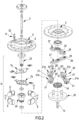
figure 2 is an exploded, partial assonometric view of the rotating machine infigure 1 ; -
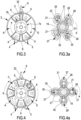
figures 3, 4 and5 are three distinct, simplified, diagrammatic and explanatory frontal views of the rotor operating sequence of the improved rotating combustion machine of the invention; -
figures 3a, 4a and5a are three distinct, simplified, diagrammatic and explanatory frontal views of the sequence of operation of the members of the mechanical transmission means of the improved rotating combustion engine of the invention, each one of which shows the position assumed by the mechanical transmission means when the rotor assumes the corresponding position shown in the respective front view infigures 3, 4 and5 . - The improved rotating combustion machine of the invention, typically a four-stroke, spark-ignition engine, operating according to an Otto cycle, is diagrammatically shown in
figure 1 , where it is indicated by reference numeral 1 as a whole. - As it can be seen, such a rotating combustion machine 1 comprises, according to the technical teachings suggested by
Italian Patent no 1378900 - a
stator 2, in which an inner combustion chamber 3 is defined, having an annular or substantially toroidal profile, asuction port 4 for introducing an operating fluid, such as a supporter of combustion-fuel mixture into the inner chamber itself, and a discharge port 5 for letting the operating fluid out from aforesaid inner combustion chamber 3; - a plurality of substantially torus-shaped orbiting
pistons 6, connected in this case to tworotors figures 3, 4 , and5 , a variable pair of adjacentorbiting pistons 6 dynamically and consecutively divide the inner chamber 3 into a suction sector A of the operating fluid, a compression sector C of the operating fluid, an expansion sector E of the burnt gases and a discharge sector S of the burnt gases outside through the discharge port 5 (sectors in which the respective stroke of an Otto cycle is performed); - ignition means, indicated as a whole by
reference numeral 8, for the combustion of the operating fluid, interposed between the compression sector C and the expansion sector E of the inner combustion chamber 3, with which they communicate; - mechanical transmission means, indicated as a whole by reference numeral 9, connected to the
rotors primary shaft 10, to which they transmit the motion, adapted to be placed by the operating fluid into rotation about a linear axis Y, so that theorbiting pistons 6 slide in rotation within the inner chamber 3, one following the other, simultaneously with the rotation of the mechanical transmission means 9 and of therotors - According to the invention, the improved rotating combustion machine 1 comprises an injection circuit, indicated as a whole by
reference numeral 11, cooperating with thestator 2 to convey a pressurized cooling fluid L (typically water) in nebulized or sprayed form into the expansion sector E of the inner combustion chamber 3, the cooling fluid being contained in aservice tank 12 belonging to theinjection circuit 11, once the operating fluid has been combusted by the ignition means 8 and during the rotation of the mechanical transmission means 9 and of therotors - In particular, by way of example only, the
injection circuit 11 comprises amain delivery pipe 13 connected to the upper part P of the expansion sector E of the internal combustion chamber 3 defined within thestator 2. - Additionally, the
injection circuit 11 appropriately further comprises pumping means, such as at least avolumetric pump 14, adapted to draw the cooling fluid L from theservice tank 12 and introduce it under pressure into the expansion sector E of the internal combustion chamber 3. - Preferably but not necessarily, the
injection circuit 11 includes a spray nozzle, not shown in the accompanying figures, facing the expansion sector E of the internal combustion chamber 3 and adapted to nebulize or spray the cooling fluid L. - More in detail, the aforesaid spray nozzle is arranged at the
first end 13a of themain delivery pipe 13, the one directly facing (and communicating with, or facing) the expansion sector E of the internal combustion chamber 3. - Advantageously, the
injection circuit 11 further comprises anon-return valve 15 arranged downstream of thevolumetric pump 14 and upstream of thefirst end 13a of themain delivery pipe 13. - By way of preferred and non-binding example, the
non-return valve 15 is arranged at asecond end 13b of themain flow pipe 13, opposite to thefirst end 13a defined above. - Preferably but not exclusively, the
injection circuit 11 of the cooling fluid L further comprises acompensator 16 arranged downstream of thevolumetric pump 14, in line with this in theinitial duct 32 of theinjection circuit 11. - Preferably but not exclusively, the
injection circuit 11 further comprises anauxiliary return pipe 17 provided with valve means, such as a solenoid valve, which normally take an open position when the cooling fluid L is introduced under pressure into the expansion sector E of the inner combustion chamber 3 of thevolumetric pump 14 and a closed position when the cooling fluid L must remain in theservice tank 12 for any reason. - According to the embodiment of the invention described herein, the mechanical transmission means 9 are of the type indicated in the
Italian Patent no. 1378900 - at least one fixed solar toothed wheel 19 (which acts as a ring of a gear), integral with the
stator 2 and, in particular, coaxial with the inner combustion chamber 3; - a
planetary support rotor 20 integral with theprimary shaft 10 and adapted to be put into rotation about the linear axis Y coaxially with the solartoothed wheel 19; - a plurality of satellite toothed wheels 21 (which each act as pinions of a gear and which in this preferred case are four in number because they ensure the maximum balancing of the structural assembly); the
satellite toothed wheels 21 are pivoted on the supportingplanetary rotor 20 and engage in the solartoothed wheel 19 from two by two opposite and symmetrically arranged parts with respect to the linear axis Y; - two
interconnection hubs 23, 24, each associated and coaxial with one of therespective rotors levers rotors interconnection hubs 23, 24 and thesatellite toothed wheels 21, each of suchtransverse levers radial cams reference numeral 29, which mutually connect theinterconnection hubs 23, 24 and thesatellite toothed wheels 21. - In practice, the
transverse levers primary shaft 10 of the mechanical transmission means 9 and are arranged axially close to each other on planes which are mutually distinct but parallel, thus defining longitudinal directions of development which are mutually offset according to a cross-like configuration. -
Figure 2 shows that, preferably, the eccentric means 29 project longitudinally and orthogonally from aside face 21a of each of thesatellite toothed wheels 21 on the primitive diameter of which they are positioned, at a point different from the center of thesatellite toothed wheels 21; this design concept gives rise to the eccentricity with which theinterconnection hubs 23, 24 are connected to thesatellite toothed wheels 21. - Furthermore, the eccentric means 29 comprise, preferably but not exclusively, two projecting
pins radial cams pins hubs 23, 24 and therotors figures 3a, 4a and5a . - Based on the above, the sliding of the orbiting
pistons 6 in the inner combustion chamber 3 takes place simultaneously to the rotation of therotors planetary rotor 20 and theinterconnection hubs 23, 24 about the linear axis Y and the rotation of thesatellite toothed wheels 21 about the fixed solartoothed wheel 19 and the sliding of the eccentric means 29 in the slottedradial cams - The ignition means 8 preferably comprise a
spark plug 22 of the traditional type, clearly visible infigures 2 ,3 ,4 and5 . - It is worth noting that in further embodiments of the improved rotating combustion engine of the invention, not accompanied by reference drawings, the mechanical transmission means may comprise a number of interconnecting hubs and transverse connecting levers different from the one described above and shown in the appended figures; such a number varies according to the number of rotors provided in the rotating combustion engine of the current invention.
- Upon implementation, changes could be made to the improved rotating combustion engine of the current invention, e.g. consisting of a different number of rotors as that previously described and shown in the appended figures, because this number may vary according to the construction choices starting from one.
- Additionally, other variants of implementation may be made to the improved rotating combustion engine claimed herein, which are not accompanied by explanatory reference figures, in which the mechanical transmission means have a different construction concept as that described above and found in the following figures, which does not affect the advantage brought by the present invention.
- Finally, it is apparent that many other variants may be made to the improved rotating combustion machine, without departing from the scope of the appended claim.
Claims (13)
- A rotating combustion machine (1) comprising:- a stator (2) in which an inner combustion chamber (3) is defined, having an annular or substantially toroidal profile and presenting at least one suction port (4) for introducing an operating fluid into said inner chamber (3) and at least one discharge port (5) for exiting said operating fluid from said inner chamber (3);- a plurality of orbiting pistons (6), connected with one or more rotors (7a, 7b) coaxial to said inner chamber (3) and made sliding in rotation in said inner chamber (3) in such a way that a variable pair of adjacent orbiting pistons (6) dynamically and consecutively divides said inner chamber (3) into a suction sector (A) of said operating fluid, a compression sector (C) of said operating fluid, an expansion sector (E) of the burnt gases and a discharge sector (S) of said burnt gases;- ignition means (8) of the combustion of said operating fluid, interposed between said compression sector (C) and said expansion sector (E) of said inner combustion chamber (3);- mechanical transmission means (9), connected with said rotors (7a, 7b) and with a primary shaft (10) to which they transmit the motion, suitable to be placed by said operating fluid in rotation around a linear axis (Y), in such a way that said orbiting pistons (6) slide in rotation inside said inner chamber (3), one following the other, simultaneously with the rotation of said mechanical transmission means (9) and of said rotors (7a , 7b) around said linear axis (Y),characterized in that it comprises an injection circuit (11), cooperating with said stator (2) in such a way as to convey inside said expansion sector (E) of said inner combustion chamber (3) a cooling fluid (L) in atomized or powder form, contained in a service tank (12) belonging to said injection circuit (11), once said combustion of said operating fluid by said ignition means (8) has been occurred and during said rotation of said mechanical transmission means (9) and of said rotors (7a, 7b) around said linear axis (Y).
- Machine (1) according to claim 1), characterized in that said injection circuit (11) comprises a main delivery pipe (13) connected with the upper part (P) of said expansion sector (E) of said inner combustion chamber (3).
- Machine (1) according to claim 1) or 2), characterized in that said injection circuit (11) comprises at least one volumetric pump (14) suitable to draw said cooling fluid (L) from said service tank (12) and inject it under pressure into said expansion sector (E) of said inner combustion chamber (3).
- Machine (1) according to any of the previous claims, characterized in that said injection circuit (11) includes a spray nozzle facing said expansion sector (E) of said inner combustion chamber (3) and suitable to nebulize or spray said cooling fluid (L).
- Machine (1) according to claim 4) when dependent on claim 2), characterized in that said spraying nozzle is arranged at a first end (13a) of said main delivery pipe (13), that one facing towards said expansion sector (E) of said inner combustion chamber (3).
- Machine (1) according to claim 3), characterized in that said injection circuit (11) includes a non-return valve (15) arranged downstream said volumetric pump (14).
- Machine (1) according claim 6) when claim 3) depends on claim 2), characterized in that said non-return valve (15) is arranged at a second end (13b) of said main delivery pipe (13), opposite to a first end (13a) facing said expansion sector (E) of said inner combustion chamber (3).
- Machine (1) according to claim 3), characterized in that said injection circuit (11) comprises a compensator (16) arranged downstream said volumetric pump (14).
- Machine (1) according to claim 3), characterized in that said injection circuit (11) comprises an auxiliary return pipe (17) provided with valve means (18) which normally take an open position when said cooling fluid (L) is introduced under pressure into said expansion sector (E) of said inner combustion chamber (3) and a closed position when said cooling fluid (L) must remain in said service tank (12).
- Machine (1) according to any of the previous claims, characterized in that said mechanical transmission means (9) comprise:- at least one fixed solar toothed wheel (19), integral with said stator (2) and coaxial with said inner combustion chamber (3);- a planetary support rotor (20) integral with said primary shaft (10) and suitable to be rotated around said linear axis (Y) coaxially with said solar toothed wheel (19);- a plurality of satellite toothed wheels (21), pivoted on said planetary rotor (20) and engaging in said solar toothed wheel (19) from two by two opposite and symmetrically arranged parts with respect to said linear axis (Y);- one or more interconnection hubs (23, 24), each associated and coaxial with one of said rotors (7a, 7b) and coupled with one or more transverse connecting levers (25, 26), coaxial with said rotors (7a, 7b) and interposed between said interconnection hubs (23, 24) and said satellite toothed wheels (21), each of said transverse levers (25, 26) having a pair of slotted radial cams (27, 28) suitable to slidably receive eccentric means (29) which connect said interconnection hubs (23, 24) with said satellite toothed wheels (21).
- Machine (1) according to claim 10), characterized in that said eccentric means (29) project longitudinally and orthogonally from a side face (21a) of each of said satellite toothed wheels (21) on the primitive diameter of which they are positioned, at a point different from the center of said satellite toothed wheels (21).
- Machine (1) according to claim 10) or 11), characterized in that said eccentric means (29) comprise a pair of projecting pins (30, 31), each of which is engaged in a respective one of said slotted radial cams ( 27, 28) inside which said projecting pins (29, 30) slide during the rotation of said interconnection hubs (23, 24) and of said rotors (7a, 7b) around said linear axis (Y).
- Machine (1) according to any of claims 10) to 12), characterized in that the sliding of said orbiting pistons (6) in said inner combustion chamber (3) takes place simultaneously to the rotation of said rotors (7a, 7b), of said planetary rotor (20) and of said interconnection hubs (23, 24) around said linear axis (Y) and to the rotation of said satellite toothed wheels (21) around said fixed solar toothed wheel (19) and to the sliding of said eccentric means (29) in said slotted radial cams (27, 28).
Applications Claiming Priority (2)
| Application Number | Priority Date | Filing Date | Title |
|---|---|---|---|
| IT102019000005532A IT201900005532A1 (en) | 2019-04-10 | 2019-04-10 | IMPROVED ROTARY COMBUSTION MACHINE |
| PCT/IB2020/053385 WO2020208567A1 (en) | 2019-04-10 | 2020-04-09 | Improved rotating combustion machine |
Publications (3)
| Publication Number | Publication Date |
|---|---|
| EP3953573A1 EP3953573A1 (en) | 2022-02-16 |
| EP3953573C0 EP3953573C0 (en) | 2023-06-07 |
| EP3953573B1 true EP3953573B1 (en) | 2023-06-07 |
Family
ID=67262911
Family Applications (1)
| Application Number | Title | Priority Date | Filing Date |
|---|---|---|---|
| EP20723929.4A Active EP3953573B1 (en) | 2019-04-10 | 2020-04-09 | Improved rotating combustion machine |
Country Status (3)
| Country | Link |
|---|---|
| EP (1) | EP3953573B1 (en) |
| IT (1) | IT201900005532A1 (en) |
| WO (1) | WO2020208567A1 (en) |
Family Cites Families (19)
| Publication number | Priority date | Publication date | Assignee | Title |
|---|---|---|---|---|
| GB191128828A (en) * | 1910-12-21 | 1912-06-27 | Voelund As | Improvements in Explosion Engines with Water Injection. |
| US1329625A (en) * | 1919-05-29 | 1920-02-03 | Stuart L Noble | Internal-combustion rotary engine |
| US1729242A (en) * | 1923-03-30 | 1929-09-24 | Bregere Louis Joseph | Valveless internal-combustion engine |
| US1644564A (en) * | 1923-06-02 | 1927-10-04 | Bullington Motors | Sealing means for rotary engines |
| US1676211A (en) * | 1923-06-02 | 1928-07-03 | Bullington Motors | Transmission for rotary engines |
| US1701534A (en) * | 1926-10-26 | 1929-02-12 | Knopp Rudolph | Rotary engine |
| US1778182A (en) * | 1927-01-03 | 1930-10-14 | Frank A Bullington | Annular-cylinder combustion engine |
| GB347803A (en) * | 1930-02-28 | 1931-05-07 | John William George | Motor power plant using combustion products and steam |
| GB1155429A (en) * | 1966-11-15 | 1969-06-18 | George Romney Stewart | Rotary Piston Internal Combustion Engine |
| US3990405A (en) * | 1975-01-16 | 1976-11-09 | Joseph Kecik | Rotary internal combustion engine |
| JPH0759888B2 (en) * | 1984-03-02 | 1995-06-28 | 京セラ株式会社 | Water-injected adiabatic ceramic diesel engine |
| IT1263709B (en) | 1993-11-10 | 1996-08-27 | Antonio Cadore | Rotary driving/machine tool |
| US5832880A (en) * | 1997-07-28 | 1998-11-10 | Southwest Research Institute | Apparatus and method for controlling homogeneous charge compression ignition combustion in diesel engines |
| DE102007008565A1 (en) * | 2007-02-21 | 2008-08-28 | Klaus Schwarz | Control system for compression ratio of engine by exhaust air valve to convert waste heat of engine in kinetic energy, compress air by one part of compression stroke in combustion engine |
| UA87229C2 (en) * | 2007-12-04 | 2009-06-25 | Евгений Федорович Драчко | Rotor-piston machine with volumetric expansion |
| IT1394033B1 (en) * | 2009-05-15 | 2012-05-25 | Ponti Motors S R L | METHOD FOR THE SUPPLY OF A BURST ENGINE |
| CN102434271B (en) * | 2011-08-18 | 2013-07-10 | 刘钢 | Double-stroke reciprocating piston type fuel and vapor engine |
| US9194287B1 (en) * | 2014-11-26 | 2015-11-24 | Bernard Bon | Double cam axial engine with over-expansion, variable compression, constant volume combustion, rotary valves and water injection for regenerative cooling |
| JP6369409B2 (en) * | 2015-07-22 | 2018-08-08 | マツダ株式会社 | Engine control device |
-
2019
- 2019-04-10 IT IT102019000005532A patent/IT201900005532A1/en unknown
-
2020
- 2020-04-09 WO PCT/IB2020/053385 patent/WO2020208567A1/en not_active Ceased
- 2020-04-09 EP EP20723929.4A patent/EP3953573B1/en active Active
Also Published As
| Publication number | Publication date |
|---|---|
| EP3953573C0 (en) | 2023-06-07 |
| IT201900005532A1 (en) | 2020-10-10 |
| EP3953573A1 (en) | 2022-02-16 |
| WO2020208567A1 (en) | 2020-10-15 |
Similar Documents
| Publication | Publication Date | Title |
|---|---|---|
| US11187146B2 (en) | Compound engine system with rotary engine | |
| US7000402B2 (en) | Compound gas turbine engines and methods of operation thereof | |
| EP2653694B1 (en) | Rotary engine and rotor unit thereof | |
| US10557407B2 (en) | Rotary internal combustion engine with pilot subchamber | |
| US20130081591A1 (en) | Rotary internal combustion engine | |
| US9896990B2 (en) | Internal combustion engine with port communication | |
| US11306651B2 (en) | Method of operating an internal combustion engine | |
| US9441538B2 (en) | Engine usable as a power source or pump | |
| EP3953573B1 (en) | Improved rotating combustion machine | |
| US7621254B2 (en) | Internal combustion engine with toroidal cylinders | |
| CN104903544A (en) | Circulating piston engine | |
| CN113167172A (en) | Rotor type internal combustion engine and method of operating the same | |
| US20130118445A1 (en) | Rotary piston engine | |
| RU2119071C1 (en) | Four-stroke piston crank-link rotary internal combustion engine with torch ignition and method of its pyrotechnic starting | |
| CN107165720B (en) | Star-shaped two-stroke multi-cylinder engine | |
| RU2503833C1 (en) | Birotary air-cooled ice | |
| AU2015246708A2 (en) | Reciprocating engine | |
| JPH04101022A (en) | Oil pressure source device | |
| WO2007107974A1 (en) | Crankshaftless internal combustion engine | |
| HK1206089B (en) | Oscillating piston engine with polygonal piston | |
| JPH08135461A (en) | Opposed cylinder rotary engine | |
| OA17507A (en) | An engine usable as a power source or pump. |
Legal Events
| Date | Code | Title | Description |
|---|---|---|---|
| STAA | Information on the status of an ep patent application or granted ep patent |
Free format text: STATUS: UNKNOWN |
|
| STAA | Information on the status of an ep patent application or granted ep patent |
Free format text: STATUS: THE INTERNATIONAL PUBLICATION HAS BEEN MADE |
|
| PUAI | Public reference made under article 153(3) epc to a published international application that has entered the european phase |
Free format text: ORIGINAL CODE: 0009012 |
|
| STAA | Information on the status of an ep patent application or granted ep patent |
Free format text: STATUS: REQUEST FOR EXAMINATION WAS MADE |
|
| 17P | Request for examination filed |
Effective date: 20211110 |
|
| AK | Designated contracting states |
Kind code of ref document: A1 Designated state(s): AL AT BE BG CH CY CZ DE DK EE ES FI FR GB GR HR HU IE IS IT LI LT LU LV MC MK MT NL NO PL PT RO RS SE SI SK SM TR |
|
| DAV | Request for validation of the european patent (deleted) | ||
| DAX | Request for extension of the european patent (deleted) | ||
| REG | Reference to a national code |
Ref country code: DE Ref legal event code: R079 Ref document number: 602020012087 Country of ref document: DE Free format text: PREVIOUS MAIN CLASS: F02B0047020000 Ipc: F01C0001077000 |
|
| RIC1 | Information provided on ipc code assigned before grant |
Ipc: F02B 53/00 20060101ALI20220922BHEP Ipc: F02B 47/02 20060101ALI20220922BHEP Ipc: F01C 21/06 20060101ALI20220922BHEP Ipc: F01C 1/077 20060101AFI20220922BHEP |
|
| GRAP | Despatch of communication of intention to grant a patent |
Free format text: ORIGINAL CODE: EPIDOSNIGR1 |
|
| STAA | Information on the status of an ep patent application or granted ep patent |
Free format text: STATUS: GRANT OF PATENT IS INTENDED |
|
| INTG | Intention to grant announced |
Effective date: 20221215 |
|
| GRAS | Grant fee paid |
Free format text: ORIGINAL CODE: EPIDOSNIGR3 |
|
| GRAA | (expected) grant |
Free format text: ORIGINAL CODE: 0009210 |
|
| STAA | Information on the status of an ep patent application or granted ep patent |
Free format text: STATUS: THE PATENT HAS BEEN GRANTED |
|
| AK | Designated contracting states |
Kind code of ref document: B1 Designated state(s): AL AT BE BG CH CY CZ DE DK EE ES FI FR GB GR HR HU IE IS IT LI LT LU LV MC MK MT NL NO PL PT RO RS SE SI SK SM TR |
|
| REG | Reference to a national code |
Ref country code: GB Ref legal event code: FG4D |
|
| REG | Reference to a national code |
Ref country code: CH Ref legal event code: EP Ref country code: AT Ref legal event code: REF Ref document number: 1575687 Country of ref document: AT Kind code of ref document: T Effective date: 20230615 |
|
| REG | Reference to a national code |
Ref country code: DE Ref legal event code: R096 Ref document number: 602020012087 Country of ref document: DE |
|
| U01 | Request for unitary effect filed |
Effective date: 20230706 |
|
| U07 | Unitary effect registered |
Designated state(s): AT BE BG DE DK EE FI FR IT LT LU LV MT NL PT SE SI Effective date: 20230718 |
|
| REG | Reference to a national code |
Ref country code: LT Ref legal event code: MG9D |
|
| PG25 | Lapsed in a contracting state [announced via postgrant information from national office to epo] |
Ref country code: NO Free format text: LAPSE BECAUSE OF FAILURE TO SUBMIT A TRANSLATION OF THE DESCRIPTION OR TO PAY THE FEE WITHIN THE PRESCRIBED TIME-LIMIT Effective date: 20230907 Ref country code: ES Free format text: LAPSE BECAUSE OF FAILURE TO SUBMIT A TRANSLATION OF THE DESCRIPTION OR TO PAY THE FEE WITHIN THE PRESCRIBED TIME-LIMIT Effective date: 20230607 |
|
| PG25 | Lapsed in a contracting state [announced via postgrant information from national office to epo] |
Ref country code: RS Free format text: LAPSE BECAUSE OF FAILURE TO SUBMIT A TRANSLATION OF THE DESCRIPTION OR TO PAY THE FEE WITHIN THE PRESCRIBED TIME-LIMIT Effective date: 20230607 Ref country code: HR Free format text: LAPSE BECAUSE OF FAILURE TO SUBMIT A TRANSLATION OF THE DESCRIPTION OR TO PAY THE FEE WITHIN THE PRESCRIBED TIME-LIMIT Effective date: 20230607 Ref country code: GR Free format text: LAPSE BECAUSE OF FAILURE TO SUBMIT A TRANSLATION OF THE DESCRIPTION OR TO PAY THE FEE WITHIN THE PRESCRIBED TIME-LIMIT Effective date: 20230908 |
|
| PG25 | Lapsed in a contracting state [announced via postgrant information from national office to epo] |
Ref country code: SK Free format text: LAPSE BECAUSE OF FAILURE TO SUBMIT A TRANSLATION OF THE DESCRIPTION OR TO PAY THE FEE WITHIN THE PRESCRIBED TIME-LIMIT Effective date: 20230607 |
|
| PG25 | Lapsed in a contracting state [announced via postgrant information from national office to epo] |
Ref country code: IS Free format text: LAPSE BECAUSE OF FAILURE TO SUBMIT A TRANSLATION OF THE DESCRIPTION OR TO PAY THE FEE WITHIN THE PRESCRIBED TIME-LIMIT Effective date: 20231007 |
|
| PG25 | Lapsed in a contracting state [announced via postgrant information from national office to epo] |
Ref country code: SM Free format text: LAPSE BECAUSE OF FAILURE TO SUBMIT A TRANSLATION OF THE DESCRIPTION OR TO PAY THE FEE WITHIN THE PRESCRIBED TIME-LIMIT Effective date: 20230607 Ref country code: SK Free format text: LAPSE BECAUSE OF FAILURE TO SUBMIT A TRANSLATION OF THE DESCRIPTION OR TO PAY THE FEE WITHIN THE PRESCRIBED TIME-LIMIT Effective date: 20230607 Ref country code: RO Free format text: LAPSE BECAUSE OF FAILURE TO SUBMIT A TRANSLATION OF THE DESCRIPTION OR TO PAY THE FEE WITHIN THE PRESCRIBED TIME-LIMIT Effective date: 20230607 Ref country code: IS Free format text: LAPSE BECAUSE OF FAILURE TO SUBMIT A TRANSLATION OF THE DESCRIPTION OR TO PAY THE FEE WITHIN THE PRESCRIBED TIME-LIMIT Effective date: 20231007 Ref country code: CZ Free format text: LAPSE BECAUSE OF FAILURE TO SUBMIT A TRANSLATION OF THE DESCRIPTION OR TO PAY THE FEE WITHIN THE PRESCRIBED TIME-LIMIT Effective date: 20230607 |
|
| PG25 | Lapsed in a contracting state [announced via postgrant information from national office to epo] |
Ref country code: PL Free format text: LAPSE BECAUSE OF FAILURE TO SUBMIT A TRANSLATION OF THE DESCRIPTION OR TO PAY THE FEE WITHIN THE PRESCRIBED TIME-LIMIT Effective date: 20230607 |
|
| REG | Reference to a national code |
Ref country code: DE Ref legal event code: R097 Ref document number: 602020012087 Country of ref document: DE |
|
| PLBE | No opposition filed within time limit |
Free format text: ORIGINAL CODE: 0009261 |
|
| STAA | Information on the status of an ep patent application or granted ep patent |
Free format text: STATUS: NO OPPOSITION FILED WITHIN TIME LIMIT |
|
| U20 | Renewal fee for the european patent with unitary effect paid |
Year of fee payment: 5 Effective date: 20240320 |
|
| 26N | No opposition filed |
Effective date: 20240308 |
|
| PG25 | Lapsed in a contracting state [announced via postgrant information from national office to epo] |
Ref country code: MC Free format text: LAPSE BECAUSE OF FAILURE TO SUBMIT A TRANSLATION OF THE DESCRIPTION OR TO PAY THE FEE WITHIN THE PRESCRIBED TIME-LIMIT Effective date: 20230607 |
|
| PG25 | Lapsed in a contracting state [announced via postgrant information from national office to epo] |
Ref country code: MC Free format text: LAPSE BECAUSE OF FAILURE TO SUBMIT A TRANSLATION OF THE DESCRIPTION OR TO PAY THE FEE WITHIN THE PRESCRIBED TIME-LIMIT Effective date: 20230607 |
|
| REG | Reference to a national code |
Ref country code: CH Ref legal event code: PL |
|
| GBPC | Gb: european patent ceased through non-payment of renewal fee |
Effective date: 20240409 |
|
| PG25 | Lapsed in a contracting state [announced via postgrant information from national office to epo] |
Ref country code: GB Free format text: LAPSE BECAUSE OF NON-PAYMENT OF DUE FEES Effective date: 20240409 |
|
| PG25 | Lapsed in a contracting state [announced via postgrant information from national office to epo] |
Ref country code: GB Free format text: LAPSE BECAUSE OF NON-PAYMENT OF DUE FEES Effective date: 20240409 Ref country code: CH Free format text: LAPSE BECAUSE OF NON-PAYMENT OF DUE FEES Effective date: 20240430 |
|
| PG25 | Lapsed in a contracting state [announced via postgrant information from national office to epo] |
Ref country code: IE Free format text: LAPSE BECAUSE OF NON-PAYMENT OF DUE FEES Effective date: 20240409 |
|
| U20 | Renewal fee for the european patent with unitary effect paid |
Year of fee payment: 6 Effective date: 20250320 |
|
| PG25 | Lapsed in a contracting state [announced via postgrant information from national office to epo] |
Ref country code: CY Free format text: LAPSE BECAUSE OF FAILURE TO SUBMIT A TRANSLATION OF THE DESCRIPTION OR TO PAY THE FEE WITHIN THE PRESCRIBED TIME-LIMIT; INVALID AB INITIO Effective date: 20200409 |
|
| PG25 | Lapsed in a contracting state [announced via postgrant information from national office to epo] |
Ref country code: HU Free format text: LAPSE BECAUSE OF FAILURE TO SUBMIT A TRANSLATION OF THE DESCRIPTION OR TO PAY THE FEE WITHIN THE PRESCRIBED TIME-LIMIT; INVALID AB INITIO Effective date: 20200409 |
|
| U20 | Renewal fee for the european patent with unitary effect paid |
Year of fee payment: 7 Effective date: 20260310 |